

Page 1
The power behind competitiveness
Delta InfraSuite
Power Management
Static Transfer Switch
User Manual
www.deltapowersolutions.com
Page 2

Save This Manual
This manual contains important instructions and warnings that you should
follow during the installation, operation, storage and maintenance of this
product. Failure to heed these instructions and warnings will void the warranty.
Copyright © 2016 by Delta Electronics Inc. All Rights Reserved. All rights of this
User Manual (“Manual”), including but not limited to the contents, information,
and figures are solely owned and reserved by Delta Electronics Inc. (“Delta”).
The Manual can only be applied to the operation or the use of this product. Any
disposition, duplication, dissemination, reproduction, modification, translation,
extraction, or usage of this Manual in whole or in part is prohibited without the prior
written permission of Delta. Given that Delta will continuously improve and develop
the product, changes may be made to the information in this Manual at any time
without obligation to notify any person of such revision or changes. Delta will make
all possible efforts to secure the accuracy and the integrity of this Manual. Delta
disclaims any kinds or forms of warranty, guarantee, or undertaking, either expressly
or implicitly, including but not limited to the completeness, faultlessness, accuracy,
non-infringement, merchantability or tness for a particular purpose of the Manual.
InfraSuite Power Management
II
Page 3

Table of Contents
Table of Contents
Chapter 1 : Important Safety Instructions --------------------------- 1
1.1 Important Safety Notes ---------------------------------------- 1
1.2 Electrical Warnings ---------------------------------------------- 1
1.3 Standard Compliance ------------------------------------------ 2
Chapter 2 : Product Introduction --------------------------------------- 3
2.1 Product Description --------------------------------------------- 3
2.2 Features ----------------------------------------------------------- 3
Chapter 3 : Package and Storage -------------------------------------- 4
3.1 Package Contents ----------------------------------------------- 4
3.2 Storage ------------------------------------------------------------- 4
Chapter 4 : Installation ----------------------------------------------------- 5
Chapter 5 : Wiring ----------------------------------------------------------- 7
Chapter 6 : Operation -----------------------------------------------------11
6.1 Front Panel -------------------------------------------------------11
6.2 Rear Panel -------------------------------------------------------13
6.3 Operation ---------------------------------------------------------16
Chapter 7 : InsightPower SNMP IPv6 for STS ---------------------17
7.1 Introduction of InsightPower SNMP IPv6 for STS ------17
7.2 SNMP IPv6 Features ------------------------------------------17
7.3 Top View and Front View of SNMP IPv6 -----------------18
7.4 Console Management -----------------------------------------19
7.5 Upgrade -----------------------------------------------------------23
III
Page 4

7.6 STS Command Settings --------------------------------------25
7.7 Key Generation for SSH --------------------------------------29
Chapter 8 : Troubleshooting --------------------------------------------31
Appendix 1 : Specications ---------------------------------------------32
Appendix 2 : Warranty ----------------------------------------------------33
InfraSuite Power Management
IV
Page 5

Chapter 1 Important Safety Instructions
Chapter 1 : Important Safety Instructions
1.1 Important Safety Notes
z
z
Only qualied personnel can service this equipment.
z
z
Follow the following precautions when working on this unit.
1. Remove watches, rings, or other metal objects.
2. Use tools with insulated handles.
3. Examine the packing container. Notify the carrier immediately if any damage
is present.
4. Do not disassemble the unit.
5. Do not operate the unit near water or in an area with excessive humidity.
6. Keep liquid and foreign objects from getting inside the unit.
7. Do not operate the unit close to gas or re.
z
z
Upstream circuit breaker must be added for each input. The recommended
breaker is D curve 16A.
z
z
Verify whether the branch circuit breaker or fuse on service feed is correct.
z
z
Verify line voltage requirements and the supplied line voltage prior to installation.
1.2 Electrical Warnings
z
z
When servicing this equipment, you will need to remove its protective covers
and disconnect the input power. Please observe great caution during these pro-
cedures. Only qualied personnel can service this equipment.
z
z
Check that power cords, plugs, and outlets are in good condition.
1
Page 6

1.3 Standard Compliance
z
z
Safety
UL (US) (UL 60950) CE (EU) (IEC 60950)
z
z
EMI
CISPR 22 Class A and FCC Class A
z
z
EMS
IEC 61000-4-2
IEC 61000-4-3
IEC 61000-4-4
IEC 61000-4-5
IEC 61000-4-6
IEC 61000-4-8
IEC 61000-4-11
z
z
IPv6 Certication
IPv6 Ready Logo Phase 2 (Core for Host, Logo ID 02-C-000624)
InfraSuite Power Management
2
Page 7

Chapter 2 Product Introduction
Chapter 2 : Product Introduction
2.1 Product Description
The STS is designed to guarantee the uninterrupted operation of sensitive equipment. It is powered by two independent power sources and automatically makes a
rapid switch from one source to the other when the original power supplying to its
connected load fails.
The user can know the power flow and the STS’s status from the user-friendly
front panel, and can read and write parameters via the built-in NETWORK port and
LOCAL port located at the rear of the unit. The STS is designed to be efcient and
reliable.
2.2 Features
z
z
Self-test function
Power-on self-test
Manual self-test
z
z
Withstands high inrush current
SCR design withstands high inrush current during transferring process.
3
Page 8
Chapter 3 : Package and Storage
3.1 Package Contents
1
2
3
×
2
4 5
4
×
6
4
×
×
8
7 8
10
×
STS package contains the following items.
No. Item Quantity
1
2
3
4
5
6
7
8
STS module 1 PC
Extension Ethernet cable 1 PC
Bracket Ear 2 PCS
Rack nut 4 PCS
Rack screw 4 PCS
Bracket screw 8 PCS
Wire Mount 10 PCS
Cable Tie 10 PCS
3.2 Storage
10
×
Please store the STS in its original package and in a dry place. Keep the storage
temperature between -15°C~ +50°C.
InfraSuite Power Management
4
Page 9
Chapter 4 Installation
Chapter 4 : Installation
z
z
Front Installation
1
Use the eight bracket screws (provided) to attach the two bracket ears
(provided) to the lateral mounting holes located in the front of the STS.
Please see Figure 4-1.
Bracket Ear x 1
Bracket Screw X 4
Bracket Ear x 1
Bracket Screw X 4
(Figure 4-1)
2
Use the four rack screws (provided) and four rack nuts (provided) to x the
STS on your rack. Please see Figure 4-2.
Rack Screw x 2
Rack Nut x 2
Rack Nut x 2
Rack Screw x 2
(Figure 4-2)
5
Page 10
z
z
Rear Installation
1
Use the eight bracket screws (provided) to attach the two bracket ears
(provided) to the lateral mounting holes located at the rear of the STS.
Please see Figure 4-3.
Bracket Ear x 1
Bracket Screw X 4
Bracket Ear x 1
Bracket Screw X 4
(Figure 4-3)
2
Use the four rack screws (provided) and four rack nuts (provided) to x the
STS on your rack. Please see Figure 4-4.
Rack Screw x 2
Rack Screw x 2
Rack Nut x 2
InfraSuite Power Management
Rack Nut x 2
(Figure 4-4)
6
Page 11
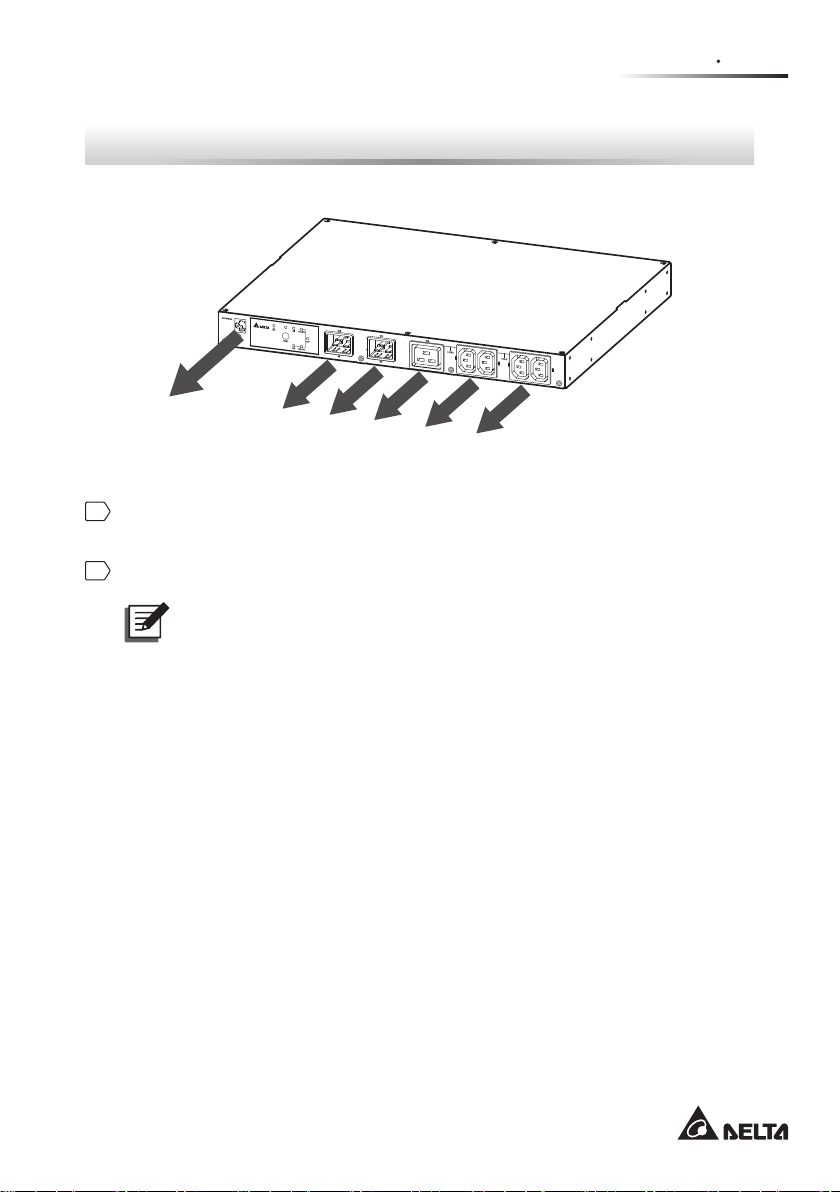
Chapter 5 Wiring
Ethernet Network
To UPS 1
To UPS 2
To load
To load
To load
Chapter 5 : Wiring
(Figure 5-1: Front view)
1
Use input power cables (not provided) to connect the STS and two UPSs (UPS1
(S1) is the preferred source).
2
Use output power cables (not provided) to connect the STS and loads.
NOTE :
To avoid the loose input/ output power cables, please use the provided
wire mounts and cables ties to x the input/ output power cables to the
outlets/ sockets firmly. Please refer to the following procedures and
gures.
7
Page 12
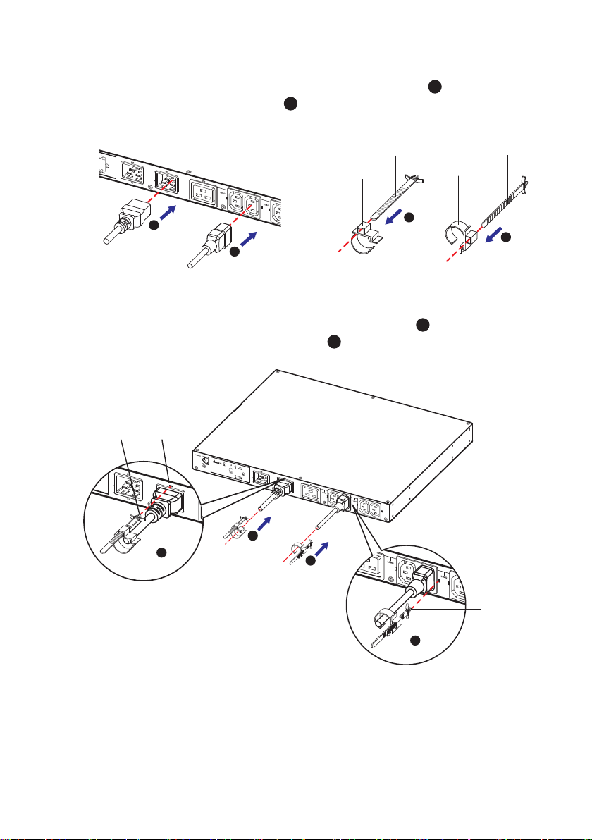
A. Firmly insert the power cables into the outlets/ sockets ( 1 ) and insert the
cable ties into the wire mounts (
2
), Please refer to Figure 5-2.
Cable Tie
Wire Mount
1
1
Wire Mount
2
Cable Tie
2
(Figure 5-2)
B. Firmly insert the wire mounts into the power cables ( 3 ) and insert each
cable tie’s peak into the according slot (
Cable
Tie’s Peak
Slot
3
4
4
). Please refer to Figure 5-3.
3
Slot
InfraSuite Power Management
Cable
Tie’s Peak
4
(Figure 5-3)
8
Page 13

C. Clip each wire mount rmly (
5
5
). Please refer to Figure 5-4.
Chapter 5 Wiring
Wire Mount
Wire Mount
5
(Figure 5-4)
3
Connect to the Ethernet Network. There are two methods.
1. Method 1 (Front Application):
Use the provided extension Ethernet cable to connect the rear panel’s
NETWORK port and the rear panel’s TRANSFER PORT; please see Figure
1
5-5
. Use a user-supplied Ethernet cable to connect to the front panel’s
NETWORK port; please see Figure 5-5
1
2
.
2
NETWORK
LOCAL
TRANSFER
RESET
PORT
(Figure 5-5: Rear View)
9
Page 14

2. Method 2 (Rear Application):
Use a user-supplied Ethernet cable to connect to the rear panel’s
NETWORK port; please see Figure 5-6.
NETWORK
LOCAL
TRANSFER
RESET
PORT
(Figure 5-6: Rear view)
InfraSuite Power Management
10
Page 15

6.1 Front Panel
Chapter 6 Operation
Chapter 6 : Operation
NETWORK
S1 S1-ON
O/P
TEST
S2 S2-ON
S1
S2
78
TEST
6
LOAD
123
S1 S1-ON
O/P
S2 S2-ON
4
LOAD
No. Item Description
1
S1 LED Green. The LED indicates the condition of input source 1. If the
input source 1 is within the acceptable range, the LED will light
up as green. If the input source 1 is out of the acceptable range,
the LED will be off.
2
S2 LED Green. The LED indicates the condition of input source 2. If the
input source 2 is within the acceptable range, the LED will light
up as green. If the input source 2 is out of the acceptable range,
the LED will be off.
5
3
4
S1_ON
LED
S2_ON
LED
Green. If the STS uses input source 1 to supply power to the
output, the LED will light up as green. If not, the LED will be off.
Green. If the STS uses input source 2 to supply power to the
output, the LED will light up as green. If not, the LED will be off.
11
Page 16

No. Item Description
5
O/P
LED
Green. The LED indicates the output condition (voltage is >
60Vac). If there is output, the LED will light up as green. If not,
the LED will be off.
6
Test
Button
Use this button to test the STS. Press the button, the STS will
transfer to the 2nd source for 1 minute and then transfer back to
the original preferred source.
7
Test
LED
Green. If you press the test button, the STS will be on test and
the Test LED will ash (on: 0.5s; off: 0.5s). In normal operation,
the LED will be off.
8
Fault
LED
Red. If the STS has any internal fault, the LED will light up as
red. If the STS has any environmental fault, the LED will ash
(on: 0.5s; off: 0.5s). Via the rear panel’s NETWORK port, fault
messages will be sent to a connected PC. From the PC, you can
see error codes as follows
Internal Fault
Error Code Meaning
E11
E12
Over temperature (due to detection of S1
heat-sink temperature)
Over temperature (due to detection of S2
heat-sink temperature)
E13 Auxiliary power 1 circuit failure
E14 Auxiliary power 2 circuit failure
E21 Input relay of S1 is open
E22 Input relay of S1 is short
E23 Input relay of S2 is open
E24 Input relay of S2 is short
E25 Input SCR of S1 is open
E26 Input SCR of S1 is short
E27 Input SCR of S2 is open
E28 Input SCR of S2 is short
InfraSuite Power Management
12
Page 17

No. Item Description
8
Fault
LED
Environmental Fault
Error Code Meaning
E01 Output overload
E02
E03
E04
Over temperature (due to detection of
ambient temperature)
Output temperature warning (due to detection
of S1 heat-sink temperature)
Over temperature warning (due to detection
of S2 heat-sink temperature)
6.2 Rear Panel
Chapter 6 Operation
NETWORK
LOCAL
RESET
TRANSFER
PORT
1 2 3
NETWORK
4
LOCAL
RESET
5
13
Page 18

No. Item Description
NETWORK
1
2
3
4
Port
LOCAL
Port
RESET
Button
LED
Indicators
Connects to the Ethernet Network.
Connects to a workstation with an RJ45 to DB9 cable to
congure the system.
Resets InsightPower SNMP IPv6 for STS (hereafter referred
to as SNMP IPv6). This does not affect the operation of the
STS.
NET LED (green) indicates network communication status.
STS LED (amber) indicates the STS’s communication status.
NETWORK
NET LED STS LED
LED Condition Meaning
NET LED OFF Ethernet is unlinked.
NET LED Green Ethernet is linked.
STS LED OFF
1. Initialization
2. SNMP IPv6 abnormality
STS LED Amber SNMP IPv6 abnormality
STS LED Blinking
InfraSuite Power Management
14
Every
second
Every
50 ms
Poor connection
between the STS
and the SNMP IPv6.
Normal connection
between the STS
and the SNMP IPv6.
Page 19

No. Item Description
Chapter 6 Operation
5
DIP
Switches
Set up operation mode. Please refer to the following table.
DIP Switch 2DIP Switch 1
1 2
ON
DIP
Switch 1
OFF OFF
OFF ON
ON OFF N/A Invalid state.
ON ON
DIP
Switch 2
Operation
Mode
Normal
Mode
Pass
Through
Mode
Congura-
tion Mode
Description
The built-in SNMP IPv6
provides the STS’s
status information and
parameters through a
network system.
The built-in SNMP
IPv6 stops polling the
STS but transfers the
communication data
between the LOCAL
port and the STS.
In this mode, the user
can login through
the LOCAL port and
congure the built-in
SNMP IPv6’s settings.
15
Page 20

6.3 Operation
(L)
(N)
(G)
(L)
(N)
(G)
UPS
(Source 1)
UPS
(Source 2)
2 poles circuit breaker
(L1)
(N1)
(G)
2 poles circuit breaker
(L2)
(N2)
(G)
ATS
S1
(L)
To the
(N)
sensitive
equipment
(G)
S2
After power connection, the STS will automatically perform power-on self-test. After
the test, the STS will start supplying power to its connected equipment. You can
also press the ‘Test Button’ to force the STS to execute self-test.
InfraSuite Power Management
16
Page 21

Chapter 7 InsightPower SNMP IPv6 for STS
Chapter 7 : InsightPower SNMP IPv6 for STS
7.1 Introduction of InsightPower SNMP IPv6 for STS
The InsightPower SNMP IPv6 for STS, hereafter referred to as SNMP IPv6, is
built in the STS and is a device that provides an interface between the STS and
a network. It communicates with the STS, acquires its information and remotely
manages the STS via a network system. The SNMP IPv6 supports public protocols
including SNMP and HTTP. You can effortlessly congure this SNMP IPv6 using a
network system and easily obtain your STS’s status and manage your STS via the
SNMP IPv6.
7.2 SNMP IPv6 Features
z
z
Network STS management
Allows remote management of the STS from any workstation through Internet or
Intranet.
z
z
Remote STS monitoring via SNMP & HTTP
Allows remote monitoring of the STS using SNMP NMS, Delta MIB (Management
Information Base) or a Web Browser.
z
z
STS and system conguration from any client (password protected)
Sets the STS and system parameters through a Web Browser.
z
z
Event logs & metering data keeping
Provides a history data of the STS’s power events, power quality and status.
z
z
Other features and supported protocols include:
- User notication via SNMP Traps and e-mail
- Network Time Protocol
- Telnet conguration
- BOOTP/ DHCP
- HTTPS, SSH, SFTP and SNMPv3 security protocols
17
Page 22

- RADIUS (Remote Authentication Dial In User Service) login and local
authentication
- Remote event log management through syslog
- IPv6 Ready Logo certied (ID 02-C-000624)
DEFAULT SETTING
User Name: admin
Password: password
DHCP Client: Enable
IPv4 Address: 192.168.1.100
7.3 Top View and Front View of SNMP IPv6
z
z
Top View
Network Port
LED Indicators
Local Port
Reset Button
Dip Switches
z
z
Front View
Network Port
LED Indicators Local Port Reset Button
InfraSuite Power Management
18
1 2
ON
Dip Switches
Page 23

Chapter 7 InsightPower SNMP IPv6 for STS
7.4 Console Management
You can manage the SNMP IPv6 through the LOCAL port. Please use an RJ45 to
DB9 cable to connect the SNMP IPv6’s LOCAL port and your workstation’s COM
port. Make sure both of the DIP switches are set to the OFF position (normal mode).
The baud-rate of the workstation’s COM setting should be 2400 bps.
z
z
Web Card Main Menu
+========================+
Web Card Main Menu
| |
+========================+
Web Card Version 01.12.11f
MAC Address 00-30-ab-26-b1-b4
[1].User Manager
[2].TCP/IP Setting
[3].Network Parameter
[4].Time Server
[5].Soft Restart
[6].Reset All To Default
[d].Device Communication
[z].Exit Without Save
[0].Save And Exit
Please Enter Your Choice =>
z
z
User Manager
+========================+
User Manager
| |
+========================+
RADIUS
[1].RADIUS Auth: Disable
[2].Server:
[3].Secret:
[4].Port: 1812
---------------Local Auth
Administrator
[5].Account: admin
[6].Password: ********
[7].Limitation: Only in This LAN
Device Manager
[8].Account: device
[9].Password: ********
[a].Limitation: Only in This LAN
Read Only User
[b].Account: user
[c].Password: ********
[d].Limitation: Allow Any
[0].Back To Previous Menu
Please Enter Your Choice =>
19
Page 24

z
z
TCP/ IP Setting
+========================+
TCP/IP Setting
| |
+========================+
[1].IPv4 Address: 192.168.1.100
[2].IPv4 Subnet Mask: 255.255.255.0
[3].IPv4 Gateway IP: 192.168.1.254
[4].IPv4 DNS or WINS IP:192.168.1.254
[5].DHCPv4 Client: Enable
[6].IPv6 Address: ::
[7].IPv6 Prefix Length: 0
[8].IPv6 Gateway IP: fe80::226:Sbff:fecc:fdal
[9].IPv6 DNS IP: ::
[a].DHCPv6: Disable
[b].Host Name(NetBIOS): INSIGHTPOWER
[c].System Contact:
[d].System Location:
[e].Auto-Negotiation: Enable
[f].Speed: 100M
[g].Duplex: Full
[h].Status Stable: 3
[i].Telnet Idle Time: 60 Seconds
[0].Back To Previous Menu
Please Enter Your Choice =>
z
z
Network Parameter
+========================+
Network Parameter
| |
+========================+
[1].HTTP Server: Enable
[2].HTTPS Server: Enable
[3].Telnet Server: Disable
[4].SSH/SFTP Server: Enable
[5].FTP Server: Enable
[6].Syslog: Disable
[7].HTTP Server Port: 80
[8].HTTPS Server Port: 443
[9].Telnet Server Port: 23
[a].SSH Server Port: 22
[b].FTP Server Port: 21
[c].Syslog Server1:
[d].Syslog Server2:
[e].Syslog Server3:
[f].Syslog Server4:
[g].SNMP Get,Set Port: 161
[0].Back To Previous Menu
Please Enter Your Choice =>
InfraSuite Power Management
20
Page 25

z
z
Time Server
Chapter 7 InsightPower SNMP IPv6 for STS
+========================+
| |
+========================+
[1].Time Selection: SNTP
[2].Time Zone: +0 hr
[3].1st Time Server:
[4].2nd Time Server:
[5].Manual Date: 01/01/2000 (MM/DD/YYYY)
[6].Manual Time: 00:00:00 (hh:mm:ss)
[0].Back To Previous Menu
Please Enter Your Choice =>
z
z
Soft Restart
+========================+
| |
+========================+
Web Card Version 01.12.11f
MAC Address 00-30-ab-26-b1-b4
[1].User Manager
[2].TCP/IP Setting
[3].Network Parameter
[4].Time Server
[5].Soft Restart
[6].Reset All To Default
[d].Device Communication
[z].Exit Without Save
[0].Save And Exit
Please Enter Your Choice => 5
The Web Card Will Restart.
Are You Sure? [Y]es/[N]o =>
Time Server
Web Card Main Menu
21
Page 26

z
STS> Vs1
216.8
STS> Vs2
217.9
STS> Iout
8.1
STS> Vout
217.1
STS> Vbp2s
180.0
STS> Vbs2p
180.0
STS> Tdp2s
12.0
STS> Tds2p
12.0
STS> TempF
96
STS> TempC
36
STS> Age
1075878
STS> Time
13:3:24 07/18 2011
STS> XCount
4402
STS> Prefer
S1
STS> DevID
12345678901234567890
STS> Serial
STS> Tprevl
13:35:16 07/18/2011
STS> Event1
0x0029
STS> Log
10
STS> Log 1
13:35:16 07/18/2011 0x0029
STS>
STS> SetDevID 1234567890abcdefghijklmn
STS> DevID
12345678901234567890
STS> SetDevID 1234567890abcdefghij
STS> DevID
1234567890abcdefghij
STS>
z
Device Communication
You can enter the STS Command Mode below by selecting Device Communication.
InfraSuite Power Management
22
Page 27

Chapter 7 InsightPower SNMP IPv6 for STS
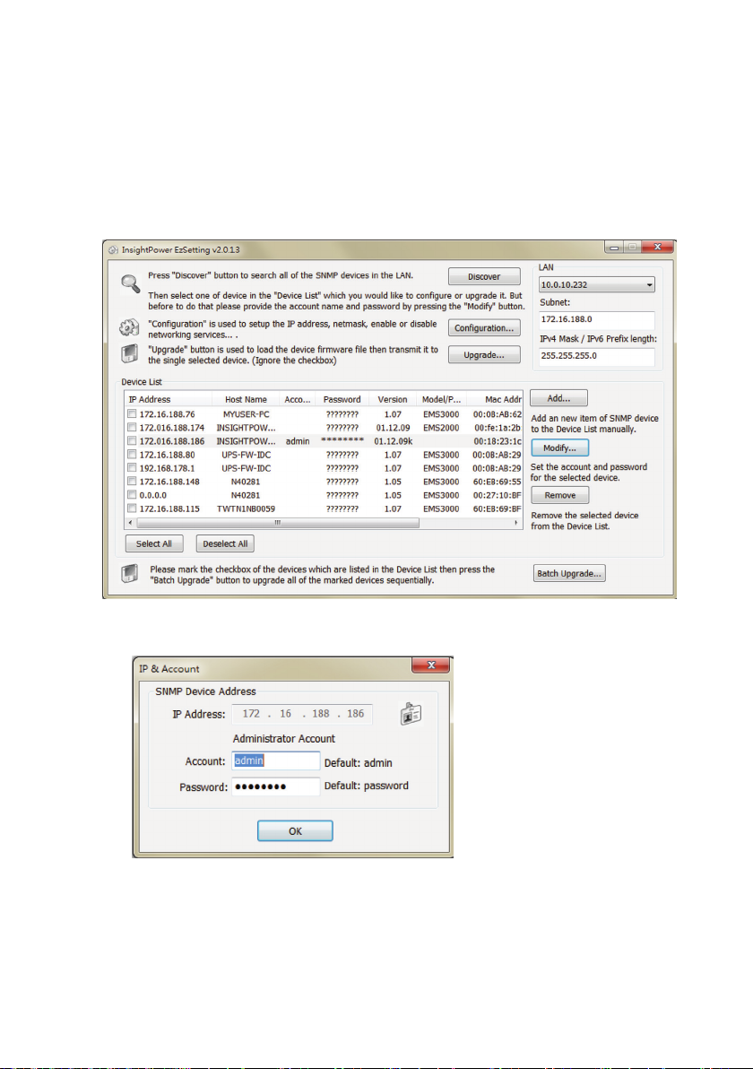
7.5 Upgrade
z
z
Upgrade via Web
You can upgrade the SNMP IPv6’s rmware or the STS’s rmware through the
InsightPower SNMP IPv6 for STS Web (please see the following gure). The
SNMP IPv6 will restart after finishing self-upgrade. If you upload the STS’s
rmware to the Web, you can see the STS’s rmware upgrade progress from the
Web.
z
z
Upgrade via FTP/ SFTP
You can also upgrade the SNMP IPv6’s rmware or the STS’s rmware by using
FTP or SFTP program. Make sure you upload correct images to upgrade_snmp
when upgrading SNMP IPv6’s rmware, and upload correct images to upgrade_
device when upgrading the STS’s rmware.
23
Page 28
z
z
Upgrade via EzSetting
You can also upgrade the SNMP IPv6’s rmware or the STS’s rmware by using
EzSetting.
1. Click Discover. A list of SNMP devices is shown. Select a device from the
Device List, and click Modify.
2. Enter Administrator account and password.
InfraSuite Power Management
24
Page 29

Chapter 7 InsightPower SNMP IPv6 for STS
3. Click Upgrade. The upgrade dialog box pops up. Click Browse to select
a valid firmware binary file. Verify the firmware version shown under File
Information, and then click Upgrade Now to continue.
7.6 STS Command Settings
Command Description Parameter Response
Info Report summary
information.
TempF Report internal STS
fahrenheit temperature.
TempC Report internal STS
celsius temperature.
Age Report internal STS age. N/A #
Time Report present time. N/A hh:mm:ss MM/DD/
XCount Report number of times
that STS has transferred.
Model Report the model name. N/A <model name string>
FWVer Report the FW version. N/A <version string>
FWDate Report the FW release
date.
Serial Report the unit’s serial
number.
N/A <Command>:
[<response>] [<unit>]
N/A #
N/A #
YYYY
N/A #
N/A YYYY-MM-DD
N/A <Device serial string>
25
Page 30

Command Description Parameter Response
DevID Report the unit’s device
N/A <Device ID string>
ID.
Prefer Report the preferred
N/A S1 or S2
source.
Sens Report the sensitivity. N/A hi or low
Mode Report the operation
mode.
N/A Initialization
Diagnosis
Off
S1
S2
Safe
Fault
Vout Report the output voltage. N/A #.#
Iout Report the output current. N/A #.#
Vs1 Report the primary
N/A #.#
voltage.
Vs2 Report the secondary
N/A #.#
voltage.
Fs1 Report the primary
N/A #.#
frequency.
Fs2 Report the secondary
N/A #.#
frequency.
Vtp2s Report the primary to
N/A #.#
secondary trip voltage.
Vts2p Report the secondary to
N/A #.#
primary trip voltage.
Vbp2s Report the primary to
N/A #.#
secondary brownout
voltage.
Vbs2p Report the secondary to
N/A #.#
primary brownout voltage.
InfraSuite Power Management
26
Page 31

Chapter 7 InsightPower SNMP IPv6 for STS
Command Description Parameter Response
Tdp2s Report the recover time
N/A #.#
of transfer from primary to
secondary.
Tds2p Report the recover time of
N/A #.#
transfer from secondary to
primary.
Mvs1 Report the max voltage
N/A #.#
of comparing cycles for
primary AC blackout.
Mvs2 Report the max voltage
N/A #.#
of comparing cycles for
secondary AC blackout.
Mts1 Report the max time of
N/A #.#
comparing cycles for
primary AC blackout.
Mts2 Report the max time of
N/A #.#
comparing cycles for
secondary AC blackout.
Log Report the event code and
time of prior transfer.
Tprev[1..9] Report the time of prior
transfer/event.
1 ~ 10 hh:mm:ss MM/DD/
YYYY 0x#
N/A hh:mm:ss MM/DD/
YYYY
Tprev1 is the most recent
time.
Event[1..9] Report the event code for
N/A 0x#
prior transfer.
Event1 is the most recent
event.
ClearLog Clear event log. N/A Various kinds
SetTime Set the present time. hh:mm:ss
Various kinds
[MM/DD/
YYYY]
SetDate Set the present date. MM/DD/YYYY Various kinds
27
Page 32

Command Description Parameter Response
SetPrefer Set the preferred source. 1 or 2 Various kinds
SetDevID Set the unit's device ID. <20
Various kinds
characters>
alphanumeric
only
SetVtp2s Set the primary to
165.0 ~ 175.0 Various kinds
secondary trip voltage.
SetVts2p Set the secondary to
165.0 ~ 175.0 Various kinds
primary trip voltage.
SetVbp2s Set the primary to
180.0 ~ 264.0 Various kinds
secondary brownout
voltage.
SetVbs2p Set the secondary to
180.0 ~ 264.0 Various kinds
primary brownout voltage.
SetTdp2s Set the recover time of
12.0 ~ 1800.0 Various kinds
transfer from primary to
secondary.
SetTds2p Set the recover time of
12.0 ~ 1800.0 Various kinds
transfer from secondary to
primary.
SetMvs1 Set the max voltage of
30 ~ 50 Various kinds
comparing cycles for
primary AC blackout.
SetMvs2 Set the max voltage of
30 ~ 50 Various kinds
comparing cycles for
secondary AC blackout.
SetMts1 Set the max time of
2.0 ~ 4.0 Various kinds
comparing cycles for
primary AC blackout.
SetMts2 Set the max time of
2.0 ~ 4.0 Various kinds
comparing cycles for
secondary AC blackout.
InfraSuite Power Management
28
Page 33

Chapter 7 InsightPower SNMP IPv6 for STS
Command Description Parameter Response
UpProcess Status of upgrade
N/A Idle / Run / Error
progress.
UpStep Stage of upgrade
progress.
N/A Init / File ID / Auth
/ Addr / Erase /
Program / Read
UpPercentage Percentage of upgrade
N/A #.#
progress.
UpResult Result of upgrade
progress.
N/A OK / No response
/ File ID fail /
Authentication fail /
Erase fail / Flash fail
/ Read fail / Upgrade
completion
UpDate Report each FW upgrade
time.
[Index] [# to
show] # = 1 -
hh:mm:ss MM/DD/
YYYY
20
AgentVer Report SNMP card
N/A AA.BB.XXX
version.
Link Check current Modbus
connection.
N/A 1 - Normal /
2 - Abnormal /
3- Upgrading
Bye Terminate remote
N/A Various kinds
connection.
7.7 Key Generation for SSH
z
z
For Linux
(1) Please download and install OpenSSH from http://www.openssh.org.
(2) Launch shell and enter the following command to create your own keys.
Please ignore it when prompted to provide passphrase.
DSA Key:ssh-keygen –t dsa
RSA Key:ssh-keygen –t rsa
(3) Upload DSA and RSA key les on the web.
29
Page 34

z
z
For Windows
(1) Please download and install PuTTY from http://www.putty.org.
(2) Run puttygen.exe from the installed directory.
(3) Select SSH-2 RSA from the Parameters area and click Key→ Generate
key pair to generate an RSA key.
(4) Select Conversions→ Export OpenSSH Key and assign a le name to the
RSA key. Please ignore it when prompted to provide key passphrase.
(5) Select SSH-2 DSA from the Parameters area and select Key→ Generate
key pair to generate a DSA key.
(6) Select Export OpenSSH Key from Conversions and assign a le name to
the DSA key. Please ignore it when prompted to provide key passphrase.
(7) Upload the DSA and RSA key les to the web.
InfraSuite Power Management
30
Page 35

Chapter 8 Troubleshooting
Chapter 8 : Troubleshooting
Problem Possible case Solution
1. Check the output (overload/ short-
All LEDs on
the front
panel are off.
The power sources,
S1 and S2, are both
absent.
circuit).
2. Check both power sources, S1 and
S2.
3. Reset the upstream circuit breakers.
Input S1 or
Input S2 LED
is off.
Fault LED
ashes.
Fault LED
lights up.
Can not
communicate
with the STS.
The corresponding
power source is
absent or out of
range.
Output overload. Reduce the connected loads.
Over temperature. Check the environment temperature.
Internal component
damage.
Wrong setting or
malfunction.
1. Check the corresponding power
source.
2. Reset the corresponding upstream
circuit breaker.
Please contact service personnel.
Refer to the user manual of
InsightPower SNMP IPv6 for STS.
31
Page 36

Appendix 1 : Specications
STS 16A
Nominal Voltage 200/ 208/ 220/ 230/ 240V
Operating Frequency 45Hz to 65HZ
Nominal Current 16A
Input Connection C20 x 2
Output Connection C13 x 4 & C19 x 1
Physical Dimensions
(W x D x H)
Weight 4.85 Kg
Environment
440 x 385 x 43 mm
Operating Temperature 0 ~ 40°C
Storage Temperature -15 ~ 50°C
Humidity
Audible Noise <40 dBA
Operating Altitude 0 to 2000m (0 to 6252 ft)
5% ~ 95% RH
(non-condensing)
NOTE :
1. Refer to the rating label for the safety rating.
2. All specications are subject to change without prior notice.
InfraSuite Power Management
32
Page 37

Appendix 2 Warranty
Appendix 2 : Warranty
Seller warrants this product, if used in accordance with all applicable instructions,
to be free from original defects in material and workmanship within the warranty
period. If the product has any failure problem within the warranty period, Seller will
repair or replace the product at its sole discretion according to the failure situation.
This warranty does not apply to normal wear or to damage resulting from improper
installation, operation, usage, maintenance or irresistible force (i.e. war, fire,
natural disaster, etc.), and this warranty also expressly excludes all incidental and
consequential damages.
Maintenance service for a fee is provided for any damage out of the warranty
period. If any maintenance is required, please directly contact the supplier or Seller.
WARNING!
The individual user should take care to determine prior to use whether the
environment and the load characteristic are suitable, adequate or safe for
the installation and the usage of this product. The User Manual must be
carefully followed. Seller makes no representation or warranty as to the
suitability or tness of this product for any specic application.
33
Page 38

Page 39

Page 40

5013236701
 Loading...