

Page 1

IFD9503
CANopen Slave Communication Module
Application Manual
Page 2

Page 3

CANopen Slave Communication Module IFD9503
Warning
3
Please read this instruction carefully before use and follow this instruction to operate the device in order to prevent
damages on the device or injuries to staff.
3
Switch off the power before wiring.
3
IFD9503 is an OPEN TYPE device and therefore should be installed in an enclosure free of airborne dust, humidity,
electric shock and vibration. The enclosure should prevent non-maintenance staff from operating the device (e.g.
key or specific tools are required for operating the enclosure) in case danger and damage on the device may occur.
3
IFD9503 is to be used for controlling the operating machine and equipment. In order not to damage it, only
qualified professional staff familiar with the structure and operation of IFD9503 can install, operate, wire and
maintain it.
3
DO NOT connect input AC power supply to any of the I/O terminals; otherwise serious damage may occur. Check
all the wirings again before switching on the power and DO NOT touch any terminal when the power is switched
on. Make sure the ground terminal
1 INTRODUCTION...................................................................................................................................3
2 COMPONENTS .................................................................................................................................... 5
3 FUNCTIONS OF IFD9503 ....................................................................................................................8
Table of Contents
1.1 IFD9503 Brief............................................................................................................................3
1.2 Features....................................................................................................................................3
2.1 Product Profile and Outline .......................................................................................................5
2.2 CANopen Connector.................................................................................................................5
2.3 Address Setup Rotary Switch....................................................................................................5
2.4 Function Setup DIP switch........................................................................................................6
2.5 Communication Ports on IFD9503............................................................................................7
3.1 Common Functions...................................................................................................................8
is correctly grounded in order to prevent electromagnetic interference.
3.2 When IFD9503 is connected to AC motor drive......................................................................12
3.3 When IFD9503 is connected to temperature controller (DTA/DTB)........................................15
3.4 When IFD9503 is connected to ASD-A servo drive.................................................................19
3.5 When IFD9503 is connected to programmable logic controller...............................................22
3.6 When IFD9503 is connected to Delta DOP-A HMI..................................................................26
3.7 When IFD9503 is connected to custom equipment.................................................................31
4 LED INDICATORS & TROUBLE-SHOOTING....................................................................................35
4.1 RUN LED.................................................................................................................................35
4.2 ERROR LED ...........................................................................................................................35
4.3 SCAN LED ..............................................................................................................................35
DVP-PLC Application Manual
1
Page 4

CANopen Slave Communication Module IFD9503
5 OBJECT DICTIONARY......................................................................................................................35
6 CONNECTION OF IFD9503 WITH OTHER EQUIPMENT ................................................................ 52
2
DVP-PLC Application Manual
Page 5

CANopen Slave Communication Module IFD9503
1 Introduction
1. To make sure that you are able to correctly install and operate IFD9503, please read this chapter carefully
before starting to use IFD9503 and keep this handy for your quick reference.
2. This chapter only provides introductory information and guidelines on IFD9503. Details of CANopen protocol
are not included. For more information on CANopen protocol, please refer to relevant references or
literatures.
3. IFD9503 is defined as CANopen slave station communication module to be used on the connection between
CANopen network and Delta programmable logi c controller, Delta AC motor drive, Delta servo drive, Delta
temperature controller and Delta human machine interface. In addition, the custom function of IFD9503
allows the custom equipment with Modbus protocol to connect with CANopen network.
1.1 IFD9503 Brief
1. RUN indicator and ERROR indicator display the connection status between IFD9503 and CANopen.
SCAN PORT indicator displays the connection status between IFD9503 and the equipment. For more
details on LED indicators, see 13.4.
2. IFD9503 sets up its node address in CANopen by two rotary switches. For more details on the switches,
see 13.2.
3. Functions of DIP switches: selecting equipment conn ected to IFD9503, selecting communication port of
IFD9503, setting up the baud rate between IFD9503 and the master. For more details on DIP switches,
see 13.2.
4. CANopen interface connects IFD9503 to CANopen network. For more details, see 13.2.
5. The communication ports allows IFD9503 to connect with Delta programmable logic controller, Delta AC
motor drive, Delta temperature controller, Delta servo drive, Delta human machine interface and
equipment with Modbus protocol. For more details, see 13.2.
1.2 Features
1. Functions supported:
z CAN2.0A protocol.
z CANopen DS301 V4.02.
2. Services supported:
z PDO (Process Data Object):
PDO1 ~ PDO8: RxPDO maps the equipment parameters writable; TxPDO maps the equipment
parameters readable. PDO information is in peer for transmitting real-time data.
z SDO (Service Data Object):
SDO information adopts ”custom machine/servo” mode for configuring slave nodes and visiting
the object dictionary of every node. There are two types of SDO: request SDO and response
SDO.
z SOP (Special Object Protocol):
Supports the default COB-ID between the connection of pre-definited master and slave.
Supportes broadcasting service (when the address is 0).
Supports SYNC service.
Supports Emergency service
DVP-PLC Application Manual
3
Page 6
CANopen Slave Communication Module IFD9503
z NMT (Network Manegment)
Supports NMT Module control.
Supports NMT Error control.
Supports Boot-up.
z Services not supported
Time Stamp service.
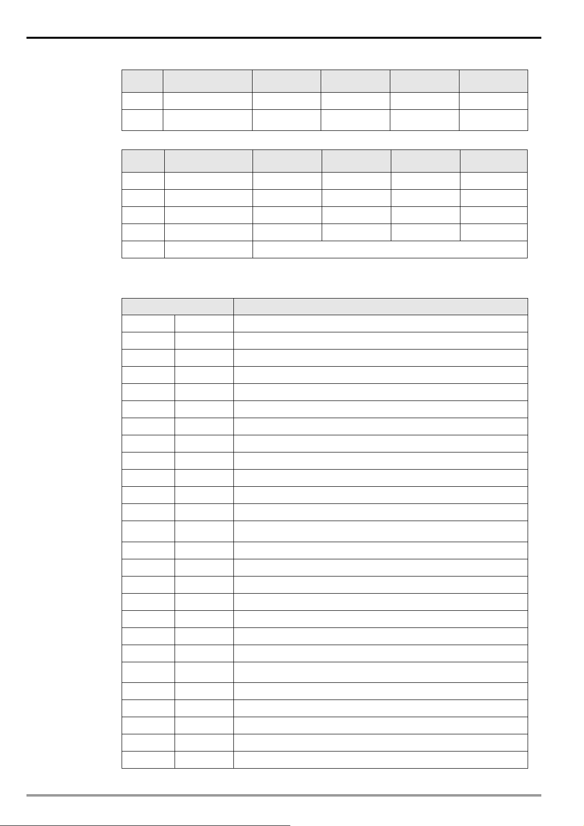
3. Specifications:
CANopen connector
Type Removable connector (5.08mm)
Transmission method CAN
Transmission cable 2 communication cables, 2 power cables and 1 shielded cable
Electrical isolation 500V DC
Communication
Message type
Baud rate
PDO
SDO
SYNC
Emergency
NMT
10 k bps (bit/sec.)
20 k bps (bit/sec.)
50 k bps (bit/sec.)
125 k bps (bit/sec.)
250 k bps (bit/sec.)
500 k bps (bit/sec.)
800 k bps (bit/sec.)
1 M bps (bit/sec.)
Supplier ID 477
Electrical specification
CANopen voltage 11 ~ 25V DC
Safety standard Under EN50178 standard
Certifications CE certified and UL certified
Environment
Operation temperature -4 ~ 122°F (-10 ~ 50°C)
Storage temperature -4 ~ 140°F (-20 ~ 60°C)
Humidity < 90%, (under normal pressure)
Altitude Max. 1,000m
Shock/vibration immunity 0.5G 9 ~ 200Hz
4
DVP-PLC Application Manual
Page 7
2 Components
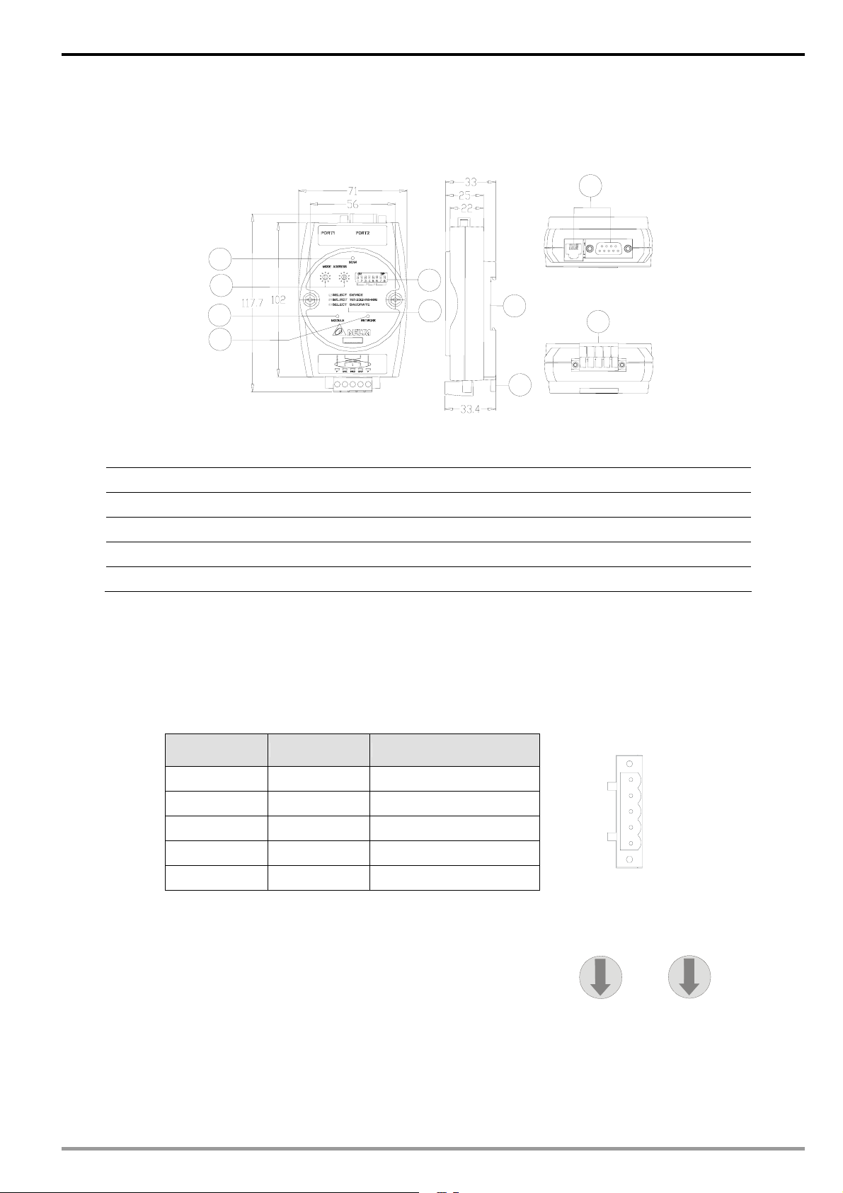
2.1 Product Profile and Outline
5
2
6
7
CANopen Slave Communication Module IFD9503
1
3
4
Unit: mm
9
8
10
1. Communicaton ports 6. RUN indicator
2. Address setup rotary switches 7. ERROR indicator
3. Function setup DIP switches 8. CANopen connector
4. Descriptions for DIP switches 9. DIN rail
5. SP (Scan Port) indicator 10. DIN rail clip
2.2 CANopen Connector
To connect with CANopen network, you can use the conne ctor en cl osed with IF D9503 or any conne ctors yo u
can buy in the store for wiring.
z Connect to th bus on CANopen
z Connect to the CANopen communication port on IFD9503
PIN Signal Description
1 V- 0V DC
2 CAN_L Signal3 SHIELD Shielded cable
4 CAN_H Signal+
5 V+ 24V DC
5
4
3
2
1
2.3 Address Setup Rotary Switch
The two rotary switches SW1 and SW2 set up the node address on
CANopen network in hexadecimal form. Setup range: 01 ~ 7F (80 ~
FF are forbidden).
4. Example:
If you need to set the node address of IFD9503 as 26 (H’1A), simply switch the corresponding rotary switch of
ID_H to “1” and the corresponding rotary switch of ID_H to “A”.
DVP-PLC Application Manual
8
9
7
A
6
5
4
3
B
C
D
E
2
F
1
0
ID_H ID_L
8
9
7
A
6
5
4
3
B
C
D
E
2
F
1
0
5
Page 8
CANopen Slave Communication Module IFD9503
Address setting Description
0 ~ 7F Valid CANopen node address
80 ~ FF Invalid CANopen node address
5. Note:
The changed values on SW1 or SW2 are only valid when IFD9503 is re-powered. When IFD9503 is
operating, changing the set value of node address will be invalid.
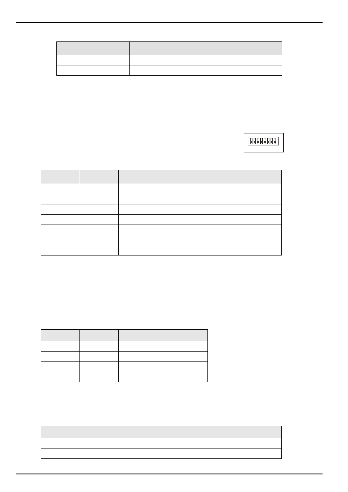
2.4 Function Setup DIP switch
The DIP switch SW3 is to be used on the equipment conne cted to IFD95 03,
the selection of communication ports and setting up the baud rate of
IFD9503 and the master in CANopen.
1. Selecting equipment connected to IFD9503
PIN 3 PIN 2 PIN 1 Equipment
Off Off On AC motor drive
Off On Off Programmable logic controller
Off On On Temperature controller
On Off Off Servo drive
On Off On Human machine interface
On On Off Custom equipment
On On On Test mode
z Example
SW3
ON
1234567
DIP
8
If the equipment connected to IFD9503 is Delta servo drive, you only need to switch PIN 3 in SW3 to “On”,
PIN 1 and PIN 2 to “Off” and re-power IFD9503.
z Note:
The changed setting of DIP switch is o nly valid when IFD95 03 is re-powe red. Wh en IFD9503 i s operating,
changing the setting of DIP switch will be invalid.
2. Selecting IFD9503 communication mode
PIN 5 PIN 4 Communication mode
Off Off RS-485
On On RS-232
Off On
On Off
z Note:
The changed setting of the communication mode is only valid when IFD9503 is re-po wered. Whe n
IFD9503 is operating, changing the setting of communication mode will be invalid.
3. Setting up baud rate
PIN 8 PIN 7 PIN 6 Baud rate
Incorrect setting
6
Off Off Off 10k bps
Off Off On 20k bps
DVP-PLC Application Manual
Page 9
CANopen Slave Communication Module IFD9503
PIN 8 PIN 7 PIN 6 Baud rate
Off On Off 50k bps
Off On On 125k bps
On Off Off 250k bps
On Off On 500k bps
On On Off 800k bps
On On On 1M bps
z Note:
The changed setting of the baud rate of CANopen is only valid when IFD9503 is re-powered. When
IFD9503 is operating, changing the baud rate will be invalid.
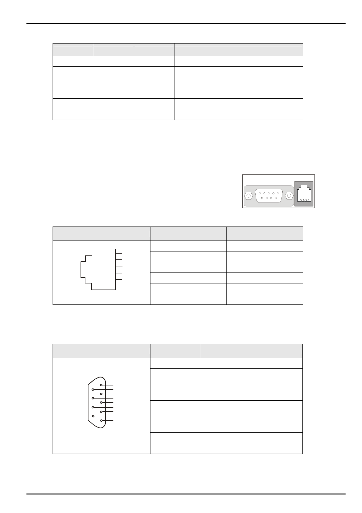
2.5 Communication Ports on IFD9503
The communication ports on IFD9503 are used for the conn ection the
equipment (Delta programmable logic controller, Delta AC motor drive,
Delta temperature controller, Delta servo drive, Delta human machine
interface and custom equipment).
1. PORT 1 PIN definition:
PORT 1 sketch PIN Description
PORT1
z Note:
PORT 1 supports RS-485 communi cation only.
1 N.C.
6
5
4
3
2
1
2 GND
3 DATA4 DATA+
5 N.C.
6 N.C.
PORT1PORT2
2. PORT 2 PIN definition:
PORT2 sketch PIN RS-232 RS-485
DB9 male
z Note:
PORT 2 supports RS-232 and RS-485 communication only.
DVP-PLC Application Manual
1 N.C. N.C.
2 RXD N.C.
1
6
2
7
3
8
4
9
5
3 TXD DATA4 N.C. N.C.
5 GND N.C.
6 N.C. N.C.
7 N.C. N.C.
8 N.C. DATA+
9 N.C. N.C.
7
Page 10

CANopen Slave Communication Module IFD9503
3 Functions of IFD9503
IFD9503 can be connected to different equipment. The function s of IFD9503 va ry upon the equipment conn ected
to it.
3.1 Common Functions
IFD9503 supports NMT, SYNC, EMERGENCY, PDO and SDO, among which the functions of NMT, SYNC
and SDO are fixed, and the functions of others vary upon the equipment connected to IFD9503.
1. NMT module control
This function controls the status of node controlling NMT slave through NMT master.
z Format
Master → IFD9503
COB-ID Byte 0 Byte 1
0 (H’000) Command specifier (CS) Node-ID
If Node-ID =0, the “command specifier” will be broadcasted to all IFD9503 (CANopen slave s).
Every slave will have to execute NMT.
z Commands
See below for the functions of all command specifiers:
Command specifier (CS)
H’01 Enable remote node
H’02 Disable remote node
H’80 Enter pre-operation status
H’81 Reset application layer
H’82 Reset communication
Function
z Explanation
Switching IFD9503 whose node ID = 6 to pre-operation status.
COB-ID Byte 0 Byte 1
8
H’000 H’80 H’06
2. NMT error control
This function is applicable to NMT slave node sending its own operational status back to NMT master.
z After IFD9503 is initialized and enters pre-operation status, IFD9503 will send out the only
BOOT-UP signal.
IFD9503 → master
COB-ID Byte 0
1792(H’700)+Node-ID H’00
z Supposed IFD9503 sends out one status signal during the operation, its format will be:
IFD9503 → master
COB-ID Byte 0
1792(H’700)+Node-ID NMT status
NMT status:
DVP-PLC Application Manual
Page 11

CANopen Slave Communication Module IFD9503
Stop: H’04; Operation in progre ss: H’05; Pre-operation: H’7F.
z Explanation: Assume the Node-ID of a IFD9503 is 6
When IFD9503 operation is in progress:
COB-ID Byte 0
H’706 H’05
When IFD9503 is shut down:
COB-ID Byte 0
H’706 H’04
When IFD9503 is in pre-operation status:
COB-ID Byte 0
H’706 H’7F
Communication reset or application layer reset:
COB-ID Byte 0
H’706 H’00
3. Synchronous signal -- SYNC
SYNC signal is sent out by the loop of CANopen master. SYNC does not contain any data, and its
main purpose is to request the PDO of slave node to operate in synchronous communication mode. In
this way, you can set to synchronous or asynchronous mode while using PDO.
z Format
Master → IFD9503
COB-ID
128(H’080)
4. SDO service
All SDO message are fixed at 8 bytes.
z Request: Master → IFD9503
COB-ID Byte 0 Byte 1 Byte 2 Byte 3 Byte 4 Byte 5 Byte 6 Byte 7
1536(H’600)
+Node-ID
Request
code
z Response: IFD9503 → master
COB-ID Byte 0 Byte 1 Byte 2 Byte 3 Byte 4 Byte 5 Byte 6 Byte 7
1408(H’580)
+Node-ID
Response
code
z If the “request code” (or “response code”) is different, the corresponding “request data” (or
“response data”) will also be different. See the table below.
Object index Request data
LSB MSB
Object index Response data
LSB MSB
Sub-index
of object
Sub-index
of object
bit7-0 bit15-8 bit23-16 bit31-24
bit7-0 bit15-8 bit23-16 bit31-24
Request
code
H’23 Write a 4-byte datum bit7-0 bit15-8 bit23-16 bit31-24
H’2B Write a 2-byte datum bit7-0 bit15-8 H’00 H’00
H’2F Write a 1-byte datum bit7-0 H’00 H’00 H’00
DVP-PLC Application Manual
Explanation Byte 4 Byte 5 Byte 6 Byte 7
9
Page 12
CANopen Slave Communication Module IFD9503
Request
code
H’40 Read data H’00 H’00 H’00 H’00
H’80
Explanation Byte 4 Byte 5 Byte 6 Byte 7
Stop the current SDO
command
H’00 H’00 H’00 H’00
Response
code
H’43 Read 4-byte data bit7-0 bit15-8 bit23-16 bit31-24
H’4B Read 2-byte data bit7-0 bit15-8 H’00 H’00
H’4F Read 1-byte data bit7-0 H’00 H’00 H’00
H’60 Read 1/2/4-byte data H’00 H’00 H’00 H’00
H’80 Stop SDO command End code
z When IFD9503 detects an SDO error, SDO data transmission will be terminated, and IFD9503
will respond SDO master with an end code. See the table below for all end codes:
End code (16#) Description
0503 0000 Transmission in sections: “toggle bit” has not been changed
0504 0000 SDO protocol time-out
0504 0001 “Request code” is invalid or unknown
Instruction
explanation
Byte 4 Byte 5 Byte 6 Byte 7
0504 0002 Invalid block length (in block mode)
0504 0003 Invalid serial n umber (in block mode)
0504 0004 CRC error (in block mod e)
0504 0005 Memory is full
0601 0000 When polli ng an object parameter, a polling fault appears
0601 0001 Try to execute reading request to a write only parameter
0601 0002 Try to execute writting request to a read only parameter
0602 0000 The requested index object does not exist in the object dictionary
0604 0041 Object parameters could not be mapped into PDO
0604 0042
0604 0043 Common parameters are incompatible
0604 0047 AC motor drive is incompatible inside
0606 0000 Polling fails be cause of hardware error.
0607 0010 Data type doesn’t match; the length of service parameters doesn’t match
0607 0012 Data type doesn’t match; the length of service parameters is too long
0607 0013 Data type doesn’t match; the length of service parameters is too short
0609 0011 Sub-index doesn’t exit.
0609 0030
0609 0031 Written parameters are too big
The number or length of the parameters to be mappe d have exceeded the
maximum PDO’s length
Having exceeded the parameters’ value selection range (only for writing
authority)
10
0609 0032 Witten parameters are too small
0609 0036 The maximum value of the parameter is less than the minimum value
0800 0000 General error occurs
0800 0020 Parameters could not be transmitted to or stored to application layer
DVP-PLC Application Manual
Page 13

CANopen Slave Communication Module IFD9503
End code (16#) Description
0800 0021
0800 0022
0800 0023
z Explanation: Supposed there is a slave IFD9503 (Node-ID = 6)
1. Read the ID if the IFD9503 supplier (index H’1018, sub-index H’01)
Master → IFD9503:
COB-ID Byte 0 Byte 1 Byte 2 Byte 3 Byte 4 Byte 5 Byte 6 Byte 7
H’606 H’40 H’18 H’10 H’01 H’00 H’00 H’00 H’00
IFD9503 → master:
COB-ID Byte 0 Byte 1 Byte 2 Byte 3 Byte 4 Byte 5 Byte 6 Byte 7
For the reason of local control, parameters could not be transmitted to or
stored to application layer
Because of the present status of AC motor drive, parameters could not be
transmitted or stored to application layer
Dynamic creating of the object dictionary fails or object dictionary does not
exit (e.g. object dictionary was created from a file, if this file has an error,
then the creating of object dictionary will fail)
H’586 H’43 H’18 H’10 H’01 H’DD H’01 H’00 H’00
2. Read the maximum output frequency of AC motor drive (index 2001H, sub index 01H,
supposed the value is 60.00Hz)
Master → IFD9503:
COB-ID Byte 0 Byte 1 Byte 2 Byte 3 Byte 4 Byte 5 Byte 6 Byte 7
H’606 H’40 H’01 H’20 H’01 H’00 H’00 H’00 H’00
IFD9503 → master:
COB-ID Byte 0 Byte 1 Byte 2 Byte 3 Byte 4 Byte 5 Byte 6 Byte 7
H’586 H’4B H’01 H’20 H’01 H’70 H’17 H’00 H’00
3. Write the maximum output frequency of AC motor drive (supposed the value is 50.00Hz)
Master → IFD9503:
COB-ID Byte 0 Byte 1 Byte 2 Byte 3 Byte 4 Byte 5 Byte 6 Byte 7
H’606 H’2B H’01 H’20 H’01 H’88 H’13 H’00 H’00
IFD9503 → master:
4. Index 1408 does not exist. If you read or write1408/01, IFD9503 will respond with an end
code.
Master → IFD9503:
DVP-PLC Application Manual
COB-ID Byte 0 Byte 1 Byte 2 Byte 3 Byte 4 Byte 5 Byte 6 Byte 7
H’586 H’60 H’01 H’20 H’01 H’00 H’00 H’00 H’00
COB-ID Byte 0 Byte 1 Byte 2 Byte 3 Byte 4 Byte 5 Byte 6 Byte 7
H’606 H’2B H’08 H’14 H’01 H’88 H’13 H’00 H’00
11
Page 14
CANopen Slave Communication Module IFD9503
IFD9503 → master:
COB-ID Byte 0 Byte 1 Byte 2 Byte 3 Byte 4 Byte 5 Byte 6 Byte 7
H’586 H’80 H’08 H’14 H’01 H’00 H’00 H’02 H’06
z Note:
When IFD9503 is connected to different equipments, see 13.5.1 “Communication Objects in
Object Dictionary” for the corresponding relations beween index (sub index) and equipment
parameters.
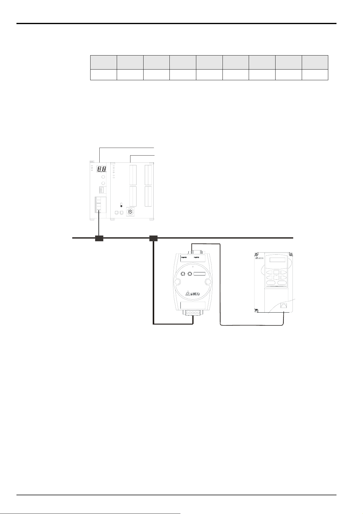
3.2 When IFD9503 is connected to AC motor drive
DVPCOPM-SL
DVP- SV
DVPCOM DVP28SV
CAN+
SHLD
CANGND
RUN
STOP
Master
CANop en
Delta VFD series
AC motor drive
RJ12
IFD9503
RS-485
1. Setting up baud rate and communication format
z Before connecting the AC motor drive to the bus, first set the communication address of the AC
motor drive to 01, baud rate to 38,400bps and communication format to 8, N, 2; RTU (the format
is fixed; other formats will be invalid).
12
z To adjust the baud rate, follow the steps listed below.
Set up the DIP switch SW3 of IFD9503 to custom equipment mode.
Connect IFD9503 to the bus of CANopen and enable the operation of IFD9503.
Modify the index parameter 5003/02 (main index: H’5003, sub index: H’02).
5003/02 = 1 → 19,200; 8, N, 2; RTU
5003/02 = 2 → 38,400; 8, N, 2; RTU (Default)
Return SW3 of IFD9503 back to AC drive mode and re-power IFD9503.
Adjust the baud rate of the AC drive to the corresponding one.
2. Functions & features
In addition, IFD9503 also supports the following two functions.
DVP-PLC Application Manual
Page 15

CANopen Slave Communication Module IFD9503
z Emergency object – EMERGENCY
When IFD9503 detects an internal error, it will send an EMCY message to the CANopen bus.
Format
IFD9503 → master
COB-ID Byte 0 Byte 1 Byte 2 Byte 3 Byte 4 Byte 5 Byte 6 Byte 7
128(H’080)
+Node-ID
Emergency error code Error register
00 00 00 00 00
LSB MSB
y Error register
The value in the error register will be mapped to index address H’1001 in the object
dictionary. V alue = 0 indicates that no error occurs. Value = 1 indicates that a general error
takes place. Value = H’80 indicates that an internal error in the equipment occurs.
y Emergency error code
Internal communication error
This error indicates the communication error between IFD9503 and AC motor drive (e.g.
communicate failure). When such error occurs, the emergency error code will be H’8101,
and the value in the error register will become 1.
CANopen bus communication error
This error indicates the communication error between CANopen master and IFD9503
slave (e.g. master disconnection). When such error occurs, the emergency error code
will be H’8130, and the value in the error register will become 1.
Insufficient length of PDO data
This error indicates that the length of Receive PDO data actually sent out is shorter than
the set data length. When such error occurs, the emergency error code will be H’8210,
and the value in the error register will become 1.
Internal error in the equipment
This error indicates the error taken place inside the AC motor drive (e.g. AC motor drive
in low voltage). When such error occurs, the emergen cy error code will be H’FFXX (XX
refers to the error code of the AC motor driv e), and the value in the error register will
become H’80. After the error is eliminated, the emergency error code will become
H’0000.
Eliminating error
When an error is eliminated, the emergency error code will become H’0000.
Explanation
Take the IFD9503 slave of node ID = 6 as the object and compare the EMERGENGY
messages sent out by IFD9503 in different error conditions.
y When in internal communication error
y When in CANopen bus communication error
DVP-PLC Application Manual
COB-ID Byte 0 Byte 1 Byte 2 Byte 3 Byte 4 Byte 5 Byte 6 Byte 7
86 01 81 01 00 00 00 00 00
13
Page 16

CANopen Slave Communication Module IFD9503
COB-ID Byte 0 Byte 1 Byte 2 Byte 3 Byte 4 Byte 5 Byte 6 Byte 7
86 30 81 01 00 00 00 00 00
y When in insufficient PDO data length
COB-ID Byte 0 Byte 1 Byte 2 Byte 3 Byte 4 Byte 5 Byte 6 Byte 7
86 10 82 01 00 00 00 00 00
y When the AC motor drive in low voltage (internal error of the equipment)
COB-ID Byte 0 Byte 1 Byte 2 Byte 3 Byte 4 Byte 5 Byte 6 Byte 7
86 0E FF 80 00 00 00 00 00
(When in low voltage, the error code in AC motor drive will be H’0E.)
y When internal error in the equipment has been eliminated
COB-ID Byte 0 Byte 1 Byte 2 Byte 3 Byte 4 Byte 5 Byte 6 Byte 7
86 00 00 80 00 00 00 00 00
y When the error is eliminated
Still other errors existing:
COB-ID Byte 0 Byte 1 Byte 2 Byte 3 Byte 4 Byte 5 Byte 6 Byte 7
86 00 00 01 00 00 00 00 00
All errors are eliminated:
COB-ID Byte 0 Byte 1 Byte 2 Byte 3 Byte 4 Byte 5 Byte 6 Byte 7
86 00 00 00 00 00 00 00 00
y Note:
IFD9503 sends out EMERGENCY message only when error occurs.
z PDO service
IFD9503 supports PDO1 ~ PDO8. For IFD9503, COB-ID of PDO can be modified but cannot be
repeated.
PDO1 (Default: Open)
y TxPDO1 (IFD9503 → master):
Send the status data of the salve (IFD9503) to the master. Preset the length of data to be
14
mapped to 2 byte and the content to be mapped to status word. You can map any readable
paramemters, maximum 8 bytes.
Default COB-ID Byte 0 Byte 1 Byte 2 Byte 3 Byte 4 Byte 5 Byte 6 Byte 7
H’180 + Node-ID Status word
y RxPDO1 (master → IFD9503):
Send the control data of the master to the slave (IFD9503). Preset the length of the data to
be mapped to 2 bytes and the content to be mapped to control word. You can map any
readable parameters, maximum 8 bytes.
DVP-PLC Application Manual
Page 17

CANopen Slave Communication Module IFD9503
Default COB-ID Byte 0 Byte 1 Byte 2 Byte 3 Byte 4 Byte 5 Byte 6 Byte 7
H’200 + Node-ID Control word
PDO2 ~ PDO8 (Default: Close)
y TxPDO (IFD9503 → master):
Send the status data of the slave (IFD9503) to the master. Preset the length of the data to
be mapped to 0 byte. You can map any readable parameters, maximum 8 bytes.
Default COB-ID Byte 0 Byte 1 Byte 2 Byte 3 Byte 4 Byte 5 Byte 6 Byte 7
H’xxxx +Node-ID
y RxPDO (master → IFD9503):
Send the control data of the master to the slave (IFD9503). Preset the length of the data to
be mapped to 0 byte. You can map any readable parameters, maximum 8 bytes.
Default COB-ID Byte 0 Byte 1 Byte 2 Byte 3 Byte 4 Byte 5 Byte 6 Byte 7
H’yyyy +Node-ID
Data tr ansmission mode
y TxPDO in IFD9503 supports many modes: synchronously non-cyclic, synchronously cy clic,
synchronous RTR, asynchronous RTR and asynchronous modes.
3.3 When IFD9503 is connected to temperature controller (DTA/DTB)
DVPCOPM-SL
DVP-SV
DVPCOM DVP28SV
RUN
CAN+
SHLD
CAN-
STOP
GND
Master
CANop en
RS-485
DTA/DTB
IFD9503
1. Setting up baud rate and communication format
z Before connecting the temperature controller to the bus, first set up the communication address
of the temperature controller to 01, baud rate to 38,400bps and communication format to 7, E, 1;
DVP-PLC Application Manual
15
Page 18

CANopen Slave Communication Module IFD9503
ASCII (the format is fixed; other formats will be invalid).
z Before communicating with DTA series temperature controller, first set the content of H’471A to
H’0001 to allow the write-in of communication.
z Before communicating with DTB series temperature controller, first set the content of H’0810 to
H’FF00 to allow the write-in of communication.
z To adjust the baud rate, follow the steps listed below.
Set up the DIP switch SW3 of IFD9503 to custom equipment mode.
Connect IFD9503 to the bus of CANop en and enable the operation of IFD9503.
Modify the index parameter 5003/04.
5003/04 = 1 → 19,200; 7, E, 1; ASCII
5003/04 = 2 → 38,400; 7, E, 1; ASCII (Default)
Return SW3 of IFD9503 back to temperature controller mode and re-po wer IF D9503.
Adjust the baud rate of the temperature controller to the corresponding one.
2. Functions & features
In addition, IFD9503 also supports the following two functions.
z Emergency object – EMERGENCY
When IFD9503 detects an internal error, it will send an EMCY message to the CANopen bus.
Format
IFD9503 → master
COB-ID Byte 0 Byte 1 Byte 2 Byte 3 Byte 4 Byte 5 Byte 6 Byte 7
128(H’080)
+Node-ID
Emergency error code Error register
00 00 00 00 00
LSB MSB
y Error register
The value in the error register will be mapped to index address H’1001 in the object
dictionary. Value = 0 indicates that no error occurs. Value = 1 incicates that a general error
takes place. Value = H’80 indicates that an internal error in the equipment occurs.
y Emergency error code
Internal communication error
This error indicates the communication error between IFD9503 and the temperature
controller (e.g. communication failure). When such error occurs, the emergency error
16
code will be H’8101, and the value in the error register content will become 1.
CANopen bus communication error
This error indicates the communication error between CANopen master and IFD9503
slave (e.g. master disconnection). When such error occurs, the emergency error code
will be H’8130, and the value in the error register will become 1.
Insufficient length of PDO data
This error indicates that the length of Receive PDO data actually sent out is shorter than
the set data length. When such error occurs, the emergency error code will be H’8210,
and the value in the error register will become 1.
Internal error in the equipment
This error indicates the error taken place inside the temperature controller (e.g. the
DVP-PLC Application Manual
Page 19

CANopen Slave Communication Module IFD9503
temperature has not been acquired immediately after the controller is switched on).
When such error occurs, the emergency error code will be H’FFXX (XX refers to the
error code of the temperature controller), and the value in the error register will become
H’80.
Eliminating error
When an error is eliminated, the emergency error code will become H’0000.
Explanation
Take the IFD9503 slave of node ID = 6 as the object and compare the EMERGENCY
messages sent out by IFD9503 in different error conditions.
y When in internal communication error
COB-ID Byte 0 Byte 1 Byte 2 Byte 3 Byte 4 Byte 5 Byte 6 Byte 7
86 01 81 01 00 00 00 00 00
y When in CANopen bus communication error
COB-ID Byte 0 Byte 1 Byte 2 Byte 3 Byte 4 Byte 5 Byte 6 Byte 7
86 30 81 01 00 00 00 00 00
y When in insufficient PDO data length
COB-ID Byte 0 Byte 1 Byte 2 Byte 3 Byte 4 Byte 5 Byte 6 Byte 7
86 10 82 01 00 00 00 00 00
y When the temperature has not yet been acquired (internal error of the equipment)
COB-ID Byte 0 Byte 1 Byte 2 Byte 3 Byte 4 Byte 5 Byte 6 Byte 7
86 02 FF 80 00 00 00 00 00
(When temperature has not been acquired, the error code in the temperature controller wil l
be H’02.)
y When the error is eliminated.
Still other errors existing:
COB-ID Byte 0 Byte 1 Byte 2 Byte 3 Byte 4 Byte 5 Byte 6 Byte 7
86 00 00 01 00 00 00 00 00
All errors are eliminated:
COB-ID Byte 0 Byte 1 Byte 2 Byte 3 Byte 4 Byte 5 Byte 6 Byte 7
86 00 00 00 00 00 00 00 00
y Note:
IFD9503 sends out EMERGENCY message only when error occurs.
z PDO service
IFD9503 supports PDO1 ~ PDO8. For IFD9503, COB-ID of PDO can be modified but cannot be
repeated.
PDO1(Default: Open )
DVP-PLC Application Manual
17
Page 20

CANopen Slave Communication Module IFD9503
y TxPDO1 (IFD9503 → master):
Send the status data of the slave (IFD9503) to the master. Preset the length of data to be
mapped to 2 bytes and the content to be mapped to present temperature value. You can
map any readable parameters, maximum 8 bytes.
Default COB-ID Byte 0 Byte 1 Byte 2 Byte 3 Byte 4 Byte 5 Byte 6 Byte 7
H’180 + Node-ID PV
y RxPDO1 (master → IFD9503):
Send the control data of the master to the slave (IFD9503). Preset the length of data to be
mapped to 2 bytes and the content to be mapped to present temperature value. You can
map any readable parameters, maximum 8 bytes.
Default COB-ID Byte 0 Byte 1 Byte 2 Byte 3 Byte 4 Byte 5 Byte 6 Byte 7
H’200 + Node-ID SV
PDO2 ~ PDO8 (Default: Close)
y TxPDO (IFD9503 → master):
Send the status date of the slave (IFD9503) to the master. Preset the length of data to be
mapped to 0 byte. You can map any readable parameter, maximum 8 bytes.
Default COB-ID Byte 0 Byte 1 Byte 2 Byte 3 Byte 4 Byte 5 Byte 6 Byte 7
H’xxxx +Node-ID
y RxPDO (master → IFD9503):
Send the control data of the master to the slave (IFD9503). Preset the length of the data to
be mapped to 0 byte. You can map any readbable parameters, maximum 8 bytes.
Default COB-ID Byte 0 Byte 1 Byte 2 Byte 3 Byte 4 Byte 5 Byte 6 Byte 7
H’yyyy +Node-ID
Data tr ansmission mode
y TxPDO in IFD9503 supports many modes: synchronously non-cyclic, synchronous cyclic,
synchronous RTR, asynchronous RTR and asynchronous modes.
18
DVP-PLC Application Manual
Page 21

CANopen Slave Communication Module IFD9503
3.4 When IFD9503 is connected to ASD-A servo drive
DVPCOPM-SL
DVP-SV
DVPCOM DVP28SV
CAN+
SHLD
CANGND
RUN
STOP
Master
CANopen
ASD-A servo drive
IFD9503
RS-23 2/ R S -485
1. Setting up baud rate and and communication format
z Before connecting the servo drive to the bus, first set the communication address of the servo
drive to 01, baud rate to 115,200bps and communication format to 7, E, 1; ASCII (the format is
fixed; other formats will be invalid).
z To adjust the baud rate, follow the steps listed below.
Set up the DIP switch SW3 of IFD9503 to custom equipment mode.
Connect IFD9503 to the bus of CANop en and enable the operation of IFD9503.
Modify the index parameter 5003/05.
5003/05 = 1 → 19,200; 7, E, 1; ASCII
5003/05 = 2 → 38,400; 7, E, 1; ASCII
5003/05 = 3 → 57,600; 7, E, 1; ASCII
5003/05 = 4 → 115,200; 7, E, 1; ASCII (Default)
Return SW3 of IFD9503 back to servo drive mode a nd re-power IFD9503.
Adjust the baud rate of the servo drive to the corre sponding one.
2. Functions & features
In addition, IFD9503 also supports the following two functions.
z Emergency object – EMERGENCY
When IFD9503 detects an internal error, it will send an EMCY message to the CANopen bus.
Format
IFD9503 → master
DVP-PLC Application Manual
19
Page 22

CANopen Slave Communication Module IFD9503
COB-ID Byte 0 Byte 1 Byte 2 Byte 3 Byte 4 Byte 5 Byte 6 Byte 7
128(H’080)
+Node-ID
Emergency error code Error register
00 00 00 00 00
LSB MSB
y Error register
The value in the error register will be mapped to index address H’1001 in the object
dictionary. V alue = 0 indicates that no error occrs. Value = 1 incicates that a general error
takes place. Value = H’80 indicates that an internal error in the equipment occurs.
y Emergency error code
Internal communication error
This error indicates the communication error between IFD9503 and the se rvo drive (e.g.
communication failure). When such error occurs, the emergency error code will be
H’8101, and the value in the error register will become 1.
CANopen bus communication error
This error indicates the communication error between CANopen master and IFD9503
slave (e.g. master disconnection). When such error occurs, the emergency error code
will be H’8130, and the value in the error register will become 1.
Insufficient length of PDO data
This error indicates that the length of Receivce PDO data actually sent out is shorter
than the set data length. When such error occurs, the emergency error code will be
H’8210, and the value in the error register will become 1.
Internal error in the equipments
This error indicates the error taken place inside the se rvo drive (e.g. sevo drive
conducts emergency stop). When such error occurs, the emergency error code will be
H’FFXX (XX refers to the error code of the servo drive), and the value in the error
register will become H’80.
Eliminating error
When an error is eliminated, the emergency error code will become H’0000.
Explanation
Take the COA slave of node ID = 6 as the object and com pare the EMERGENCY messages
sent out by IFD9503 in different error conditions.
y When in internal communication error
COB-ID Byte 0 Byte 1 Byte 2 Byte 3 Byte 4 Byte 5 Byte 6 Byte 7
86 01 81 01 00 00 00 00 00
y When in CANopen bus communication error
20
COB-ID Byte 0 Byte 1 Byte 2 Byte 3 Byte 4 Byte 5 Byte 6 Byte 7
86 30 81 01 00 00 00 00 00
y When in insufficient PDO data length
COB-ID Byte 0 Byte 1 Byte 2 Byte 3 Byte 4 Byte 5 Byte 6 Byte 7
86 10 82 01 00 00 00 00 00
DVP-PLC Application Manual
Page 23

CANopen Slave Communication Module IFD9503
y When the servo drive conducts emergency stop (i nternal error of the equipment)
COB-ID Byte 0 Byte 1 Byte 2 Byte 3 Byte 4 Byte 5 Byte 6 Byte 7
86 0D FF 80 00 00 00 00 00
(When stops urgently, the error code of srovo drive is H’0D)
y Error removed
When there is still other error exiting
COB-ID Byte 0 Byte 1 Byte 2 Byte 3 Byte 4 Byte 5 Byte 6 Byte 7
86 00 00 01 00 00 00 00 00
When all errorss have been removed
COB-ID Byte 0 Byte 1 Byte 2 Byte 3 Byte 4 Byte 5 Byte 6 Byte 7
86 00 00 00 00 00 00 00 00
y Note
Only when error status has changed that IFD9503 could send EMMERGENCY message.
z PDO service
IFD9503 supports PDO1 ~ PDO8. For IFD9503, COB-ID of PDO can be modified but cannot be
repeated.
PDO1 (Default: Open)
y TxPDO1 (IFD9503 → master):
Send the status data of the slave (IFD9503) to the master. Preset the length of data to be
mapped to 2 bytes and the content to be mapped to “status word of digital output contact”.
You can map any readable parameters, maximum 8 bytes.
Default COB-ID Byte 0 Byte 1 Byte 2 Byte 3 Byte 4 Byte 5 Byte 6 Byte 7
H’180 + Node-ID DO1~DO5
y RxPDO1 (master → IFD9503):
Send the control data of the master to the slave (IFD9503). Preset the length of data to be
mapped to 2 bytes and the content to be mapped to “control word of digital input contact”.
You can map any readable parameters, maximum 8 bytes.
Default COB-ID Byte 0 Byte 1 Byte 2 Byte 3 Byte 4 Byte 5 Byte 6 Byte 7
H’200 + Node-ID DI1~ DI8
PDO2 ~ PDO8 (Default: Close)
y TxPDO (IFD9503 → master):
Send the status date of the slave (IFD9503) to the master. Preset the length of data to be
mapped to 0 byte. You can map any readable parameters, maximum 8 bytes.
Default COB-ID Byte 0 Byte 1 Byte 2 Byte 3 Byte 4 Byte 5 Byte 6 Byte 7
H’xxxx +Node-ID
y RxPDO (master→IFD9503):
Send the control data of the master to the slave (IFD9503). Preset the length of data to be
DVP-PLC Application Manual
21
Page 24

CANopen Slave Communication Module IFD9503
mapped to 0 byte. You can map any readable parameters, maximum 8 bytes.
Default COB-ID Byte 0 Byte 1 Byte 2 Byte 3 Byte 4 Byte 5 Byte 6 Byte 7
H’yyyy +Node-ID
Data tr ansmission mode
y TxPDO in IFD9503 supports many modes: synchronously non-cyclic, synchrono usly cy clic,
synchronously RTR, asynchronously RTR and asynchronous modes.
3.5 When IFD9503 is connected to programmable logic controller
DVPCOPM-SL
DVP-SV
DVPCOM DVP28SV
CAN+
SHLD
CANGND
RUN
STOP
Master
CANop en
RS-485
Delta DVP series PLC
IFD9503
1. Setting up baud rate and communication format
z Before connecting the PLC to the bus, first set up the communication address of the PLC to 01,
baud rate to 115,200bps and communication format to 7, E, 1; ASCII (the format is fixed; other
formats will be invalid).
22
z To adjust the baud rate, follow the steps listed below.
Set up the DIP switch SW3 of IFD9503 to custom equipment mode.
Connect IFD9503 to the bus of CANop en and enable the operation of IFD9503.
Modify the index parameter 5003/03
5003/03 = 1 → 19,200; 7, E, 1; ASCII
5003/03 = 2 → 38,400; 7, E, 1; ASCII
5003/03 = 3 → 57,600; 7, E, 1; ASCII
5003/03 = 4 → 115,200; 7, E, 1; ASCII (Default)
Return SW3 of IFD9503 back to PLC mode and re-power IFD9503.
Adjust the baud rate of the PLC to the corresponding one.
DVP-PLC Application Manual
Page 25

CANopen Slave Communication Module IFD9503
2. Functions & features
In addition, IFD9503 also supports the following two functions.
z Emergency object – EMERGENCY
When IFD9503 detects an internal error, it will send an EMCY message to the CANopen bus.
Format
IFD9503 → master
COB-ID Byte 0 Byte 1 Byte 2 Byte 3 Byte 4 Byte 5 Byte 6 Byte 7
128(H’080)
+Node-ID
Emergency error code Error register
00 00 00 00 00
LSB MSB
y Error register
The value in the error register will be mapped to index address H’1001 in the object
dictionary. V alue = 0 indicates that no error occurs. Value = 1 incicates that a general error
takes place. Value = H’80 indicates that an internal error in the equipment occurs.
y Emergency error code
Internal communication error
This error indicates the communication error between IFD9503 and PLC (e.g.
communication failure). When such error occurs, the emergency error code will be
H’8101, and the value in the error register will become 1.
CANopen bus communication error
This error indicates the communication error between CANopen master and IFD9503
slave (e.g. master disconnection). When such error occurs, the emergency error code
will be H’8130, and the value in the error register will become 1.
Insufficient length of PDO data
This error indicates that the length of Receive PDO data actually sent out is shorter than
the set data length. When such error occurs, the emergency error code will be H’8210,
and the value in the error register will become 1.
Eliminating error
When an error is eliminated, the emergency error code will become H’0000.
Explanation
Take the IFD9503 slave of node ID = 6 as the object and compare the EMERGENCY
messages sent out by IFD9503 in different error conditions.
y When in internal communication error
COB-ID Byte 0 Byte 1 Byte 2 Byte 3 Byte 4 Byte 5 Byte 6 Byte 7
86 01 81 01 00 00 00 00 00
y When in CANopen bus communication error
COB-ID Byte 0 Byte 1 Byte 2 Byte 3 Byte 4 Byte 5 Byte 6 Byte 7
86 30 81 01 00 00 00 00 00
y When in insufficient PDO data length
DVP-PLC Application Manual
23
Page 26

CANopen Slave Communication Module IFD9503
COB-ID Byte 0 Byte 1 Byte 2 Byte 3 Byte 4 Byte 5 Byte 6 Byte 7
86 10 82 01 00 00 00 00 00
y When the error is eliminated.
Still other errors exiting:
COB-ID Byte 0 Byte 1 Byte 2 Byte 3 Byte 4 Byte 5 Byte 6 Byte 7
86 00 00 01 00 00 00 00 00
All errors are eliminated:
COB-ID Byte 0 Byte 1 Byte 2 Byte 3 Byte 4 Byte 5 Byte 6 Byte 7
86 00 00 00 00 00 00 00 00
y Note
IFD9503 sends out EMMERGENCY message only when error occurs.
z PDO service
IFD9503 supports PDO1 ~ PDO8. For IFD9503, COB-ID of PDO can be modified but cannot be
repeated.
Particularly for PLC, the PDO parameters in IFD9503 are divided into an upload area and
download area, featuring:
y TxPDO
TxPDO is only able to map parameter D (upload start address+0) ~ D (upload start
address+31), the 32 registers, in the upload area. By modifying the upload start address,
you can obtain different upload areas. For example,
When the upload start address = 0, the upload area will be D0 ~ D31.
When the upload start address = 10, the upload area will be D10 ~ D41.
y RxPDO
RxPDO is only able to map parameter D (download start address+0) ~ D (download start
address+31), the 32 registers, in the download area. By modifying the download start
address, you can obtain different download areas. For example,
When the download start address = 0, the download area will be D0 ~ D31.
When the download start address = 10, the download area will be D10 ~ D41.
y Note: See 13.5.1 “Communication Objects in Object Dictionary” for the corresponding
24
index and sub-index of upload start address, download st art address and all mapping
parameters.
PDO1 (Default: Open)
y TxPDO1 (IFD9503 → master):
Send the status data of the slave (IFD9503) to the master. Preset the length of data to be
st
mapped to 8 bytes and the content to be mapped to “the 1
area”. You can map any parameters in the upload area, maximum 8 bytes.
Default COB-ID Byte 0 Byte 1 Byte 2 Byte 3 Byte 4 Byte 5 Byte 6 Byte 7
H’180 + Node-ID D (up+0) D (up+1) D (up+2) D (up+3)
~ 4th registers in the upload
DVP-PLC Application Manual
Page 27

CANopen Slave Communication Module IFD9503
y RxPDO1 (master → IFD9503):
Send the control data of the master to the slave (IFD9503). Preset the length of the data to
st
be mapped to 8 bytes and the content to be mapped to “the 1
~ 4th registers in the
download area”. You can map any parameters in the download area, maximum 8 bytes.
Default COB-ID Byte 0 Byte 1 Byte 2 Byte 3 Byte 4 Byte 5 Byte 6 Byte 7
H’200 + Node-ID D (down +0) D (down +1) D (down +2) D (down +3)
PDO2 ~ PDO8 (Default: Close)
y TxPDO (IFD9503 → master):
Send the status data of the slave (IFD9503) to the master. Preset the lengrh of the data to
be mapped to 0 byte. You can map any parameters in the upload area, maximum 8 bytes.
Default COB-ID Byte 0 Byte 1 Byte 2 Byte 3 Byte 4 Byte 5 Byte 6 Byte 7
H’xxxx +Node-ID
y RxPDO (master → IFD9503):
Send the control data of the master to the slave (IFD9503). Preset the length of data to be
mapped to 0 byte. You can map any parameters in the download area, maximum 8 bytes.
Default COB-ID Byte 0 Byte 1 Byte 2 Byte 3 Byte 4 Byte 5 Byte 6 Byte 7
H’yyyy +Node-ID
Data tr ansmission mode
y TxPDO in IFD9503 supports many modes: synchronous non-cyclic, synchronous cyclic,
synchronous RTR, asynchronous RTR and asynchronous modes.
DVP-PLC Application Manual
25
Page 28

CANopen Slave Communication Module IFD9503
3.6 When IFD9503 is connected to Delta DOP-A HMI
DVPCOPM- S L
DVP-SV
DVPCOM DVP28SV
CAN+
SHLD
CANGND
RUN
STOP
Master
CANopen
Delta DOP-A HMI
IFD9503
RS-23 2/ R S - 48 5
1. Setting up baud rate and communication format
z Before connecting the HMI to the bus, first set up the baud rate to 115,200bps and
communication format to 7, E, 1; ASCII (the format is fixed; other formats will be invalid).
COM1
F1
F2
F3
COM2
z HMI as the master and IFD9503 as the slave. There are 64 virtual D devices (D0 ~ D63) in
IFD9503. CANopen master and HMI are able to map, read and write the virtual D devices in
IFD9503.
z To adjust the baud rate, follow the steps listed below.
Set up the DIP switch SW3 of IFD9503 to custom equipment mode.
Connect IFD9503 to the bus of CANop en and enable the operation of IFD9503.
Modify the index parameter 5003/06.
5003/06 = 1 → 19,200; 7, E, 1; ASCII
5003/06 = 2 → 38,400; 7, E, 1; ASCII
5003/06 = 3 → 57,600; 7, E, 1; ASCII
5003/06 = 4 → 115,200; 7, E, 1; ASCII (Default)
Return SW3 of IFD9503 back to HMI mode and re-power IFD9503.
Adjust the baud rate of the HMI to the corresponding one.
z When IFD9503 is connected to DOP HMI, set up the baud rate and communication format
following the steps below.
26
DVP-PLC Application Manual
Page 29

CANopen Slave Communication Module IFD9503
Open Screen Editor and select “File => New”. You will see the dialog box below.
1
Select “Delta DVP PLC” to be the Base Port Controll er, as step 1. Click “OK” to create a new
file.
Select “Options => Configuration => Communication”, and you will see the dialog box below.
2
3
4
5
6
Follow step 2 ~ 6: PLC Station = 1; communication format = 115,200, 7, E, 1, ASCII.
Click ”OK”.
z When the HMI connected to DNA02 is TP04/TP02, and then please set up its communication
speed and format following the procedure listed below.
Open TPEdit or and select “File => New”. You will see the dialog box below.
DVP-PLC Application Manual
27
Page 30

CANopen Slave Communication Module IFD9503
1
Select “DELTA PLC” in Set Device Type column, as step
Select “Tools => TP Object Communication Default Setting”, and you will see the dialog box
below.
1
. Click “OK” to create a new file.
2
Follow step
2. Functions & features
In addition, IFD9503 also supports the following two functions.
z Emergency object – EMERGENCY
When IFD9503 detects an internal error, it will send an EMCY message to the CANopen bus.
Format
IFD9503 → master
COB-ID Byte 0 Byte 1 Byte 2 Byte 3 Byte 4 Byte 5 Byte 6 Byte 7
128(H’080)
+Node-ID
~ 3: Set PLC ID = 1; check “Select Default PLC ID”. Click “OK”.
Emergency error
code
LSB MSB
Error
register
y Error register
3
2
00 00 00 00 00
28
The value in the error register will be mapped to index address H’1001 in the object
dictionary. V alue = 0 indicates that no error occurs. Value = 1 indicates that a general error
takes place. Value = H’80 indicates that an internal error in the equipment occurs.
y Emergency error code
CANopen bus communication error
This error indicates the communication error between CANopen master and IFD9503
slave (e.g. master disconnection). When such error occurs, the emergency error code
will be H’8130, and the value in the error register will become 1.
Insufficient length of PDO data
This error indicates that the length of Receive PDO data actually sent out is shorter than
DVP-PLC Application Manual
Page 31

CANopen Slave Communication Module IFD9503
the set data length. When such error occurs, the emergency error code will be H’8210,
and the value in the error register will become 1.
Eliminating error
When an error is eliminated, the emergency error code will become H’0000.
Explanation
Take the IFD9503 slave of node ID = 6 as the object and compare the EMERGENCY
messages sent out by IFD9503 in different error conditions.
y When in CANopen bus communication error
COB-ID Byte 0 Byte 1 Byte 2 Byte 3 Byte 4 Byte 5 Byte 6 Byte 7
86 30 81 01 00 00 00 00 00
y When in insufficient PDO data length
COB-ID Byte 0 Byte 1 Byte 2 Byte 3 Byte 4 Byte 5 Byte 6 Byte 7
86 10 82 01 00 00 00 00 00
y When the error is eliminated
Still other errors exiting:
COB-ID Byte 0 Byte 1 Byte 2 Byte 3 Byte 4 Byte 5 Byte 6 Byte 7
86 00 00 01 00 00 00 00 00
All errors are eliminated:
COB-ID Byte 0 Byte 1 Byte 2 Byte 3 Byte 4 Byte 5 Byte 6 Byte 7
86 00 00 00 00 00 00 00 00
y Note:
IFD9503 sends out EMERGENCY message only when error occurs.
z PDO service
IFD9503 supports PDO1 ~ PDO8. For IFD9503, COB-ID of PDO can be modified but cannot be
repeated..
Particularly for PLC, the PDO parameters in IFD9503 are divided into an upload area and
download area, featuring:
y TxPDO
TxPDO is only able to map 32 registers, D32 ~ D63 in the upload area.
y RxPDO
RxPDO is only able to map 32 registers, D32 ~ D63 in the download area.
PDO1 (Default: Open)
y TxPDO1 (IFD9503 → master):
Send the status data of the slave (IFD9503) to the master. Preset the length of data to be
mapped to 8 bytes and the content to be mapped to “the 1
area”. You can map any parameters in the upload area, maximum 8 bytes.
DVP-PLC Application Manual
st
~ 4th registers in the upload
Default COB-ID Byte 0 Byte 1 Byte 2 Byte 3 Byte 4 Byte 5 Byte 6 Byte 7
H’180 + Node-ID D32 D33 D34 D35
29
Page 32

CANopen Slave Communication Module IFD9503
Note: See 13.5.1 “Communication Objects in Object Dictionary” for the corresponding
index and sub-index of upload start address, download st art address and all mapping
parameters.
y RxPDO1 (master → IFD9503):
Send the control data of the master to the slave (IFD9503). Preset the length of data to be
mapped to 8 bytes and the content to be mapped to “the 1
st
~ 4th registers in the download
area”. You can map any parameters in the download area, maximum 8 bytes.
Default COB-ID Byte 0 Byte 1 Byte 2 Byte 3 Byte 4 Byte 5 Byte 6 Byte 7
H’200 + Node-ID D0 D1 D2 D3
PDO2 ~ PDO8 (Default: Close)
y TxPDO (IFD9503 → master):
Send the status data of the slave (IFD9503) to the master. Preset the length of the data to
be mapped to 0 byte. You can map any parameters in the download area, maximum 8
bytes.
Default COB-ID Byte 0 Byte 1 Byte 2 Byte 3 Byte 4 Byte 5 Byte 6 Byte 7
H’xxxx +Node-ID
y RxPDO (master → IFD9503):
Send the control data of the master to the slave equipment (IFD9503). Preset the length of
the data to be mapped to 0 byte. You can map any parameters in the download area,
maximum 8 bytes.
Default COB-ID Byte 0 Byte 1 Byte 2 Byte 3 Byte 4 Byte 5 Byte 6 Byte 7
H’yyyy +Node-ID
Data tr ansmission mode
TxPDO in IFD9503 supports many modes: synchronously non-cyclic, synchronously cyclic,
synchronous RTR, asynchronous RTR and asynchronous modes.
30
DVP-PLC Application Manual
Page 33

CANopen Slave Communication Module IFD9503
3.7 When IFD9503 is connected to custom equipment
DVPCOPM-SL
DVP-SV
DVPCOM DVP28SV
RUN
CAN+
SHLD
CAN-
STOP
GND
Master
CANop en
custom equipment
IFD9503
RS-485
1. Setting up baud rate and communication format
z Before connecting the custom equipment to the bus, first set up the communication address of
the equipment to 01, baud rate to 19,200bps and communication format to 8, N, 2; RTU (the
format is fixed; other formats will be invalid).
z To adjust the baud rate, follow the steps listed below.
Modify the index parameter 5003/07.
5003/07 = 1 → 19,200; 8, N, 2; RTU (Default)
5003/07 = 2 → 38,400; 8, N, 2; RTU
5003/07 = 3 → 57,600; 8, N, 2; RTU
5003/07 = 4 → 115,200; 8, N, 2; RTU
Re-power IFD9503 and adjust the ba ud rate of the custom equipment to the corresponding
one. Note: When IFD9503 is connected to custom equipment, IFD9503 will enter the pre-run
status automatically after it is powered in any configuration, which allows you to adjust the
baud rate and so on in that mode.
2. Functions & features
In addition, IFD9503 also supports the following two functions.
z Emergency object – EMERGENCY
When IFD9503 detects an internal error, it will send an EMCY message to the CANopen bus.
Format
IFD9503 → master
DVP-PLC Application Manual
31
Page 34

CANopen Slave Communication Module IFD9503
COB-ID Byte 0 Byte 1 Byte 2 Byte 3 Byte 4 Byte 5 Byte 6 Byte 7
128(H’080)
+Node-ID
Emergency error code Error register
00 00 00 00 00
LSB MSB
y Error register
The value in the error register will be mapped to index address H’1001 in the object
dictionary. Value = 0 indicates that no error occurs. Value = 1, it indicates that a general
error takes place. Value = H’80 indicates that an internal error in the equipment occurs.
y Emergency error code
CANopen bus communication error
This error indicates the communication error between CANopen master and IFD9503
slave (e.g. master disconnection). When such error occurs, the emergency error code
will be H’8130, and the value in the error register will become 1.
Insufficient length of PDO data
This error indicates that the length of Receive PDO data actually sent out is shorter than
the set data length. When such error occurs, the emergency error code will be H’8210,
and the value in the error register will become 1.
Eliminating error
When an error is eliminated, the emergency error code will become H’0000.
Explanation
Take the IFD9503 slave of node ID = 6 as the object and compare the EMERGENCY
messages sent out by IFD9503 in different error conditions.
y When in CANopen bus communication error
COB-ID Byte 0 Byte 1 Byte 2 Byte 3 Byte 4 Byte 5 Byte 6 Byte 7
86 30 81 01 00 00 00 00 00
y When in insufficient PDO data length
COB-ID Byte 0 Byte 1 Byte 2 Byte 3 Byte 4 Byte 5 Byte 6 Byte 7
86 10 82 01 00 00 00 00 00
y When the error is eliminated.
Still other errors exiting:
COB-ID Byte 0 Byte 1 Byte 2 Byte 3 Byte 4 Byte 5 Byte 6 Byte 7
86 00 00 01 00 00 00 00 00
All errors are eliminated:
COB-ID Byte 0 Byte 1 Byte 2 Byte 3 Byte 4 Byte 5 Byte 6 Byte 7
32
86 00 00 00 00 00 00 00 00
y Note:
IFD9503 sends out EMERGENCY message only when error occurs.
z PDO service
IFD9503 supports PDO1 ~ PDO8. For IFD9503, COB-ID of PDO can be modified but cannot be
DVP-PLC Application Manual
Page 35

CANopen Slave Communication Module IFD9503
repeated.
Particularly for custom equipment, the PDO paramete rs in IFD9503 are divided into an upload
area and download area, featuring:
y TxPDO
TxPDO is only able to map 32 parameters (sub-index addess) in the upload area (index
H’5001). For example,
5001/01 (1
5001/02 (2
If you would like to correspond the 1
(parameter address) of the connected equipment, you can write the Modbus address into
5001/01. The same rule also applies to other sub-index addresses.
y RxPDO
RxPDO is only able to map 32 parameters (sub-index addess) in the download area (index
H’5000). For example,
5000/01 (1
5000/02 (2
If you would like to correspond the 1
st
word of TxPDO1)
nd
word of TxPDO1)
st
word of RxPDO1)
nd
word of RxPDO1)
st
word of TxPDO1 to a certain Modbus address
st
word of RxPDO1 to a certain Modbus address
(parameter address) of the connected equipment, you can write the Modbus address into
5000/01. The same rule also applies to other sub-index addresses.
y Note: See 13.5.1 “Communication Objects in Object Dictionary” for the corresponding
index and sub-index of upload start address, download st art address and all mapping
parameters.
PDO1 (Default: Open)
y TxPDO1 (IFD9503 → master):
Send the status data of the slave (IFD9503) to the master. Preset the length of data to be
st
mapped to 0 byte. You can map maximum 8 bytes in the 1
TxPDO1 in the upload area. The mapping relation is corresponding and fixed. For
example,
st
Word 1 (byte 0 & byte 1) → 1
Word 2 (byte 2 & byte 3) → 2
Word 3 (byte 4 & byte 5) → 3
Word 4 (byte 6 & byte 7) → 4
Default COB-ID Byte 0 Byte 1 Byte 2 Byte 3 Byte 4 Byte 5 Byte 6 Byte 7
word of TxPDO1
nd
word of TxPDO1
rd
word of TxPDO1
th
word of TxPDO1
word of TxPDO 1 ~ 4th word of
y RxPDO1 (master → IFD9503):
Send the contol data of the master to the slave (IFD9503). Preset the length of the data to
be mapped to 0 byte. You can map maximum 8 bytes in the 1
word of RxPDO1 in the download area. The mapping relation is corresponding and fixed.
For example,
DVP-PLC Application Manual
H’180 + Node-ID
st
word of RxPDO 1 ~ 4th
st
Word 1 (byte 0 & byte 1) → 1
word of RxPDO1;
33
Page 36

CANopen Slave Communication Module IFD9503
nd
Word 2 (byte 2 & byte 3) → 2
Word 3 (byte 4 & byte 5) → 3
Word 4 (byte 6 & byte 7) → 4
Default COB-ID Byte 0 Byte 1 Byte 2 Byte 3 Byte 4 Byte 5 Byte 6 Byte 7
H’200 + Node-ID
PDO2 ~ PDO8 (Default: Close)
y TxPDO (IFD9503 → master):
Send the status data of the slave equipment (IFD9503) to the master. Preset the length of
the data to be mapped to 0 byte. You can map maximum 8 bytes. Same as TxPDO1,
PDO2 ~ PDO8 map RxPDO2 ~ RxPDO8. The mapping relation is corresponding and
fixed.
Default COB-ID Byte 0 Byte 1 Byte 2 Byte 3 Byte 4 Byte 5 Byte 6 Byte 7
H’xxxx +Node-ID
word of RxPDO1
rd
word of RxPDO1
th
word of RxPDO1
y RxPDO (master → IFD9503):
Send the control data of the master to the slave (IFD9503). Preset the length of the data to
be mapped to 0 byte. You can map maximum 8 bytes. Same as RxPDO1, PDO2 ~ PDO8
map RxPDO2 ~ RxPDO8 in the download area. The mapping relation is corresponding
and fixed.
H’yyyy +Node-ID
Default COB-ID Byte 0 Byte 1 Byte 2 Byte 3 Byte 4 Byte 5 Byte 6 Byte 7
Explanation
If the custom equipment is a Delta VFD-B AC motor drive, and we would like to control its
RUN/STOP, frequency input and monitor its operation status and frequency, follow the
explanations below:
y Map the 1
TxPDO1 and 2
st
word of RxPDO1 and 2nd word of RxPDO1 in RxPDO1 and map the 1st word of
nd
word of TxPDO1 in TxPDO1.
y Write the Modbus address corresponding to VFD-B in the index addre ss of IFD9503
through SDO, e.g. H’2000 → 5000/01, H’2001 → 5000/02; H’2101 → 5001/01, H’2103
→ 5001/02.
34
y In this way, we will be able to control the control word (H’2000), frequency command
(H’2001) and monitor the status word (H’2101) and running frequency (H’2103) in VFD-B
through RxPDO1 and TxPDO1.
y Note: You can only map the Modbus address of 16-bit word device in the dowbload area
and upload area.
Data tr ansmission mode
y TxPDO in IFD9503 supports many modes: synchronously non-cyclic, synchrono usly cy clic,
synchronous RTR, asynchronous RTR and asynchronous modes.
DVP-PLC Application Manual
Page 37

CANopen Slave Communication Module IFD9503
4 LED Indicators & Trouble-shooting
There are 3 LED indicators on IFD9503, RUN, ERROR and SCAN, for displaying the connection status of the
communication in IFD9503.
4.1 RUN LED
LED Status IFD9503 Status How to deal with it
Off No power
Green light 1 flash Stop
Green light flashes Pre-operation
Green light On Operating
Red light On NODE-ID error Check if the setting of NODE-ID of IFD9503 is correct.
4.2 ERROR LED
LED Status IFD9503 Status How to deal with it
Off No error IFD9503 operation is normal.
Red light 2 flashes Erroneous control occurs.
Red light On bus OFF
4.3 SCAN LED
LED Status IFD9503 Status How to deal with it
Off No power
Green light flashes
Green light On
Red light flashes CRC check fails
Red light On Connection fails, or no connection
The correct information of the
equipment connected has not been
detected.
The communication with the
equipment connected is normal.
Check the power of IFD9503 and make sure the
connection is normal.
1. Check if the connection between IFD9503 and the
master station is intact.
2. Check if the communication between IFD9503 and the
master station is normal.
1. Check if the bus connection is normal.
2. Re-power IFD9503.
Check the power of IFD9503 and make sure the
connection is normal.
Re-connect IFD9503 to the equipment.
1. Check if the communication cable between IFD9503
and the equipment is correct.
2. Check if there is electromagnetic interference nearby.
1. Check if the communication format of the equipment is
correct.
2. Check if IFD9503 and the equipment are correctly
connected.
3. Restart the connection and make sure the
communication cable meets the specification.
5 Object Dictionary
1. Communication objects in the object dictionary:
Index Sub-index Object name Data type
H’1000 H’00 Equipment type Unsigned 32 bits R 0x00000000
H’1001 H’00 Error register Unsigned 8 bits R 0
Predefined error field
H’1003
DVP-PLC Application Manual
H’00 Number of errors Unsigned 8 bits R 0
H’01 Standard error field Unsigned 32 bits R 0
Access
autorization
Default
35
Page 38

CANopen Slave Communication Module IFD9503
Index Sub-index Object name Data type
H’1005 H’00 COB-ID SYNC message Unsigned 32 bits RW 0x00000080
H’1008 H’00 Equipment name of suppl ier
H’100C H’00 Protection time Unsigned 16 bits RW 0
H’100D H’00 Life time factor Unsigned 8 bits RW 0
H’1014 H’00 COB-ID emergency message Unsigned 32 bits R 0x80 + Node-ID
Pulsant time of the user
H’1016
H’1017 H’00 Pulsant time of generator Unsigned 16 bits RW 0
H’1018
H’1400
H’00 Number of items Unsigned 8 bits R 1
H’01 Pulsant time of the user Unsigned 32 bits RW 0
Identification object
H’00 Number of items Unsigned 8 bits R 3
H’01 Supplier code Unsigned 32 bits R 0x000001DD
H’02 Product code Unsigned 32 bits R
H’03 Version Unsigned 32 bits R 0x00010002
RxPDO1 communication
parameter
H’00 Number of items Unsigned 8 bits R 3
H’01 COB-ID of RxPDO1 Unsigned 32 bits RW 0x0000 0200+Node-ID
Visible charater
string
Access
autorization
R IFD9503
Denpens on the
connected equipment
Default
H’1401
H’1402
H’1403
H’02 Transmission mode Unsigned 8 bits RW 0xFF
H’03 Forbidden time Unsigned 16 bits RW 0
RxPDO2 communication
parameter
H’00 Number of items Unsigned 8 bits R 3
H’01 COB-ID of RxPDO2 Unsigned 32 bits RW 0x80000000
H’02 Transmission mode Unsigned 8 bits RW 0xFF
H’03 Forbidden time Unsigned 16 bits RW 0
RxPDO3 communication
parameter
H’00 Number of items Unsigned 8 bits R 3
H’01 COB-ID of RxPDO3 Unsigned 32 bits RW 0x80000000
H’02 Transmission mode Unsigned 8 bits RW 0xFF
H’03 Forbidden time Unsigned 16 bits RW 0
RxPDO4 communication
parameter
H’00 Number of items Unsigned 8 bits R 3
H’01 COB-ID of RxPDO4 Unsigned 32 bits RW 0x80000000
H’02 Transmission mode Unsigned 8 bits RW 0xFF
36
H’1404
H’03 Forbidden time Unsigned 16 bits RW 0
RxPDO5 communication
parameter
H’00 Number of items Unsigned 8 bits R 3
H’01 COB-ID of RxPDO5 Unsigned 32 bits RW 0x80000000
DVP-PLC Application Manual
Page 39

CANopen Slave Communication Module IFD9503
Index Sub-index Object name Data type
H’02 Transmission mode Unsigned 8 bits RW 0xFF
H’03 Forbidden time Unsig ned 16 bits RW 0
RxPDO6 communication
H’1405
H’1406
H’1407
parameter
H’00 Number of items Unsigne d 8 bits R 3
H’01 COB-ID of RxPDO6 Unsigned 32 bits RW 0x80000000
H’02 Transmission mode Unsigned 8 bits RW 0xFF
H’03 Forbidden time Unsig ned 16 bits RW 0
RxPDO7 communication
parameter
H’00 Number of items Unsigne d 8 bits R 3
H’01 COB-ID of RxPDO7 Unsigned 32 bits RW 0x80000000
H’02 Transmission mode Unsigned 8 bits RW 0xFF
H’03 Forbidden time Unsig ned 16 bits RW 0
RxPDO8 communication
parameter
H’00 Number of items Unsigne d 8 bits R 3
H’01 COB-ID of RxPDO8 Unsigned 32 bits RW 0x80000000
Access
autorization
Default
H’1600
H’1601
H’02 Transmission mode Unsigned 8 bits RW 0xFF
H’03 Forbidden time Unsig ned 16 bits RW 0
RxPDO1 mapping parameter
H’00 Number of items Unsigne d 8 bits RW
H’01 The first mapped object Unsigned 32 bits RW
H’01 The sencond mapped object Unsigned 32 bits RW
H’02 The third mapped object Unsigned 32 bits RW
H’03 The forth mapped object Unsigned 32 bits RW
RxPDO2 mapping parameter
H’00 Number of items Unsigne d 8 bits RW 0
H’01 The first mapped object Unsigned 32 bits RW 0
H’01 The sencond mapped object Unsigned 32 bits RW 0
H’02 The third mapped object Unsigned 32 bits RW 0
H’03 The fourth mapped o bject Unsigned 32 bits RW 0
RxPDO3 mapping parameter
Denpens on the
connected equipment
Denpens on the
connected equipment
Denpens on the
connected equipment
Denpens on the
connected equipment
Denpens on the
connected equipment
H’00 Number of items Unsigne d 8 bits RW 0
H’01 The first mapped object Unsigned 32 bits RW 0
H’1602
H’01 The sencond mapped object Unsigned 32 bits RW 0
H’02 The third mapped object Unsigned 32 bits RW 0
H’03 The fourth mapped o bject Unsigned 32 bits RW 0
H’1603
H’00 Number of items Unsigne d 8 bits RW 0
DVP-PLC Application Manual
RxPDO4 mapping parameter
37
Page 40

CANopen Slave Communication Module IFD9503
Index Sub-index Object name Data type
H’01 The first mapped object Unsigned 32 bits RW 0
H’01 The sencond mapped object Unsigned 32 bits RW 0
H’02 The third mapped object Unsigned 32 bits RW 0
H’03 The fourth mapped o bject Unsigned 32 bits RW 0
RxPDO5 mapping parameter
H’00 Number of items Unsigned 8 bits RW 0
H’01 The first mapped object Unsigned 32 bits RW 0
H’1604
H’01 The sencond mapped object Unsigned 32 bits RW 0
H’02 The third mapped object Unsigned 32 bits RW 0
H’03 The fourth mapped o bject Unsigned 32 bits RW 0
RxPDO6 mapping parameter
H’00 Number of items Unsigned 8 bits RW 0
H’01 The first mapped object Unsigned 32 bits RW 0
H’1605
H’01 The sencond mapped object Unsigned 32 bits RW 0
H’02 The third mapped object Unsigned 32 bits RW 0
H’03 The fourth mapped o bject Unsigned 32 bits RW 0
Access
autorization
Default
H’1606
H’1607
H’1800
RxPDO7 mapping parameter
H’00 Number of items Unsigned 8 bits RW 0
H’01 The first mapped object Unsigned 32 bits RW 0
H’01 The sencond mapped object Unsigned 32 bits RW 0
H’02 The third mapped object Unsigned 32 bits RW 0
H’03 The fourth mapped o bject Unsigned 32 bits RW 0
RxPDO8 mapping parameter
H’00 Number of items Unsigned 8 bits RW 0
H’01 The first mapped object Unsigned 32 bits RW 0
H’01 The sencond mapped object Unsigned 32 bits RW 0
H’02 The third mapped object Unsigned 32 bits RW 0
H’03 The fourth mapped o bject Unsigned 32 bits RW 0
TxPDO1 communication
parameter
H’00 Number of items Unsigned 8 bits R 5
H’01 COB-ID of TxPDO1 Unsigned 32 bits RW 0x00000180+Node-ID
H’02 Transmission mode Unsigned 8 bits RW 0xFF
H’03 Forbidden time Unsigne d 16 bits RW 50
38
H’1801
H’05 Timer Unsigned 16 bits RW 100
TxPDO2 communication
parameter
H’00 Number of items Unsigned 8 bits R 5
H’01 COB-ID of TxPDO2 Unsigned 32 b its RW 0x80000000
H’02 Transmission mode Unsigned 8 bits RW 0xFF
H’03 Forbidden time Unsigne d 16 bits RW 50
DVP-PLC Application Manual
Page 41

CANopen Slave Communication Module IFD9503
Index Sub-index Object name Data type
H’05 Timer Unsigned 16 bits RW 100
TxPDO3 communication
H’1802
H’1803
parameter
H’00 Number of items Unsigne d 8 bits R 5
H’01 COB-ID of TxPDO3 Unsigned 32 bits RW 0x80000000
H’02 Transmission mode Unsigned 8 bits RW 0xFF
H’03 Forbidden time Unsigned 16 bits RW 50
H’05 Timer Unsigned 16 bits RW 100
TxPDO4 communication
parameter
H’00 Number of items Unsigne d 8 bits R 5
H’01 COB-ID of TxPDO4 Unsigned 32 bits RW 0x80000000
H’02 Transmission mode Unsigned 8 bits RW 0xFF
H’03 Forbidden time Unsigned 16 bits RW 50
H’05 Timer Unsigned 16 bits RW 100
TxPDO5 communication
parameter
H’00 Number of items Unsigne d 8 bits R 5
Access
autorization
Default
H’1804
H’1805
H’1806
H’01 COB-ID of TxPDO5 Unsigned 32 bits RW 0x80000000
H’02 Transmission mode Unsigned 8 bits RW 0xFF
H’03 Forbidden time Unsigned 16 bits RW 50
H’05 Timer Unsigned 16 bits RW 100
TxPDO6 communication
parameter
H’00 Number of items Unsigne d 8 bits R 5
H’01 COB-ID of TxPDO6 Unsigned 32 bits RW 0x80000000
H’02 Transmission mode Unsigned 8 bits RW 0xFF
H’03 Forbidden time Unsigned 16 bits RW 50
H’05 Timer Unsigned 16 bits RW 100
TxPDO7 communication
parameter
H’00 Number of items Unsigne d 8 bits R 5
H’01
H’02 Transmission mode Unsigned 8 bits RW 0xFF
H’03 Forbidden time Unsigned 16 bits RW 50
H’05 Timer Unsigned 16 bits RW 100
H’00 Number of items Unsigne d 8 bits R 5
TxPDO7的 COB-ID
TxPDO8 communication
parameter
Unsigned 32 bits RW 0x8000000 0
H’1807
H’1A00
H’01 COB-ID of TxPDO8 Unsigned 32 bits RW 0x80000000
H’02 Transmission mode Unsigned 8 bits RW 0xFF
H’03 Forbidden time Unsigned 16 bits RW 50
H’05 Timer Unsigned 16 bits RW 100
DVP-PLC Application Manual
TxPDO1mapping parameter
39
Page 42

CANopen Slave Communication Module IFD9503
Index Sub-index Object name Data type
H’00 Number of items Unsigned 8 bits RW
H’01 The first mapped object Unsigned 32 bits RW
H’02 The sencond mapped object Unsigned 32 bits RW
H’03 The third mapped object Unsigned 32 bits RW
H’04 The fourth mapped o bject Unsigned 32 bits RW
TxPDO2 mapping parameter
H’00 Number of items Unsigned 8 bits RW 0
H’01 The first mapped object Unsigned 32 bits RW 0
H’1A01
H’02 The sencond mapped object Unsigned 32 bits RW 0
H’03 The third mapped object Unsigned 32 bits RW 0
H’04 The fourth mapped o bject Unsigned 32 bits RW 0
TxPDO3mapping parameter
H’00 Number of items Unsigned 8 bits RW 0
H’01 The first mapped object Unsigned 32 bits RW 0
H’1A02
H’02 The sencond mapped object Unsigned 32 bits RW 0
Access
autorization
Default
Denpens on the
connected equipment
Denpens on the
connected equipment
Denpens on the
connected equipment
Denpens on the
connected equipment
Denpens on the
connected equipment
H’1A03
H’1A04
H’1A05
H’03 The third mapped object Unsigned 32 bits RW 0
H’04 The fourth mapped o bject Unsigned 32 bits RW 0
TxPDO4
H’00 Number of items Unsigned 8 bits RW 0
H’01 The first mapped object Unsigned 32 bits RW 0
H’02 The sencond mapped object Unsigned 32 bits RW 0
H’03 The third mapped object Unsigned 32 bits RW 0
H’04 The fourth mapped o bject Unsigned 32 bits RW 0
TxPDO5 mapping parameter
H’00 Number of items Unsigned 8 bits RW 0
H’01 The first mapped object Unsigned 32 bits RW 0
H’02 The sencond mapped object Unsigned 32 bits RW 0
H’03 The third mapped object Unsigned 32 bits RW 0
H’04 The fourth mapped o bject Unsigned 32 bits RW 0
TxPDO6 mapping parameter
H’00 Number of items Unsigned 8 bits RW 0
H’01 The first mapped object Unsigned 32 bits RW 0
H’02 The sencond mapped object Unsigned 32 bits RW 0
40
H’1A06
H’03 The third mapped object Unsigned 32 bits RW 0
H’04 The fourth mapped o bject Unsigned 32 bits RW 0
TxPDO7 mapping parameter
H’00 Number of items Unsigned 8 bits RW 0
H’01 The first mapped object Unsigned 32 bits RW 0
DVP-PLC Application Manual
Page 43

CANopen Slave Communication Module IFD9503
Index Sub-index Object name Data type
H’02 The sencond mapped object Unsigned 32 bits RW 0
H’03 The third mapped object Unsigned 32 bits RW 0
H’04 The fourth mapped o bject Unsigned 32 bits RW 0
TxPDO8 mapping parameter
H’00 Number of items Unsigne d 8 bits RW 0
H’01 The first mapped object Unsigned 32 bits RW 0
H’1A07
H’02 The sencond mapped object Unsigned 32 bits RW 0
H’03 The third mapped object Unsigned 32 bits RW 0
H’04 The fourth mapped o bject Unsigned 32 bits RW 0
Access
autorization
2. Parameter objects of Delta VFD series AC motor drive in the object dictionay
z Main index: H’2000-----user parameters
Sub-index
(hex)
1 00-00 Identity code of the AC motor drive
2 00-01 Displaying of drive’s rated current
3 00-02 Parameter reset
Parameter No. Parameter funcion
Default
┊ ┊ ┊
9 00-08 Setting up parameter protection password
A 00-09 Control method
B 00-10 Reserved
z Main index: H’2001-----basic parameters
Sub-index
(hex)
1 01-00 Setting up max. operation paramerer frequncy
2 01-01 Setting up motor’s rated frequncy
3 01-02 Setting up motor’s rated voltage
┊ ┊ ┊
16 01-21 Setting up the 4th deceleration time
17 01-22 Setting upf JOG deceleration time
18 01-23 Setting up the unit of acceleration/deceleration time
Parameter No. Parameter funcion
z Main index: H’2002-----operation method parameters
Sub-index
(hex)
1 02-00 Setting up the source of the 1st frequency instruction
Parameter No. Parameter funcion
2 02-01 Setting up the source of the 1st operation instruction
3 02-02 Selecting the stop method of motor
┊ ┊ ┊
E 02-13 Setting up the source of the 2nd frequency instruction
F 02-14 Setting up the source of the 2nd operation instruction
10 02-15 Ke yboard frequency instruction
z Main index: H’2003-----output function parameters
DVP-PLC Application Manual
41
Page 44

CANopen Slave Communication Module IFD9503
Sub-index
(hex)
1 03-00 Multi-function output relay
2 03-01 Multi-function output MO1
3 03-02 Multi-function ouput MO2
┊ ┊ ┊
D 03-12 Fan control
E 03-13 Break release frequency
F 03-14 Break engage frequncy
Parameter No. Parameter funcion
z Main index: H’2004-----input function parameters
Sub-index
(hex)
1 04-00 AUI analog input bias
2 04-01 AUI bias polarity
3 04-02 AUI input gain
┊ ┊ ┊
18 04-23 Deceleration ratio of deceleration gear
19 04-24 Inde x angle for simple index function
Parameter No. Parameter funcion
1A 04-25 Deceleration time for simple index function
z Main index: H’2005-----multi-step speed and PLC parameters
Sub-index
(hex)
1 05-00 Setting up the 1st step speed frequency
2 05-01 Setting up the 2nd step speed frequency
3 05-02 Setting up the 3rd step speed frequency
┊ ┊ ┊
21 05-32 Setting up the unit of operation time
22 05-33 The amplitude of wobble vibration
23 05-34 Wobble skip frequency
Parameter No. Parameter funcion
z Main index: H’2006-----protection parameters
Sub-index
(hex)
1 06-00 Over-voltage stall prevention
2 06-01 Over-current stall prevention during accel
3 06-02 Over-current stall prevention during operation
┊ ┊ ┊
Parameter No. Parameter funcion
42
11 06-16 User-defined low-voltage detection level
12 06-17 User-defined low-voltage detection time
13 06-18 Reserved
z Main index: H’2007-----motor parameters
Sub-index
(hex)
1 07-00 Motor rated current
Parameter No. Parameter funcion
DVP-PLC Application Manual
Page 45
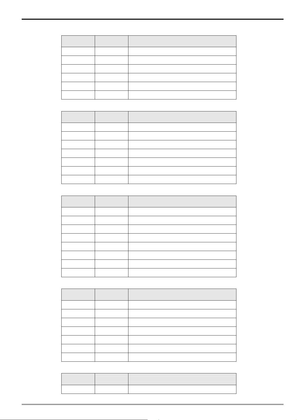
CANopen Slave Communication Module IFD9503
Sub-index
(hex)
2 07-01 Motor no-load current
3 07-02 Torque compensation
┊ ┊ ┊
E 07-13 Slip compensation time constant
F 07-14 Accumulative motor operation time (min)
10 07-15 Accumulative motor operation time (day)
Parameter No. Parameter funcion
z Main index: H’2008-----special parameters
Sub-index
(hex)
1 08-00 DC braking current level
2 08-01 DC braking time during start-up
3 08-02 DC braking time during stopping
┊ ┊ ┊
15 08-20 Speed search frequncy during start-up
16 08-21 Auto reset time at restart after fault
17 08-22 Compensation coefficient for motor instability
Parameter
address
Parameter funcion
z Main index: H’2009----- communication parameters
Sub-index
(hex)
1 09-00 Communication address
2 09-01 Transmission speed
3 09-02 Transmission fault treatment
4 09-03 Time-out detection
5 09-04 Communication protocol
6 09-05 Reserved
7 09-06 Reserved
8 09-07 Response delay time
Parameter No. Parameter funcion
z Main index: H’200A-----PID control parameters
Sub-index
(hex)
1 10-00 Selecting PID feedback input terminal
2 10-01 Gain over the PID detection value
3 10-02 Proportional gain (P)
┊ ┊ ┊
Parameter No. Parameter funcion
F 10-14 PG slip compensation limit
10 10-15 PG output sampling time
11 10-16 PID offset level
z Main index: H’200B-----multiple motors control parameters
Sub-index
(hex)
1 11-00 Selecting V/f curve
DVP-PLC Application Manual
Parameter No. Parameter funcion
43
Page 46

CANopen Slave Communication Module IFD9503
Sub-index
(hex)
2 11-01 Start-up frequency of the auxiliary motor
3 11-02 Stop frequency of the auxiliary motor
4 11-03 Delay time before starting the auxiliary motor
5 11-04 Delay time before stopping the auxiliary motor
6 11-05 Sleep/wake up detection time
7 11-06 Sleep frequency
8 11-07 Wake-up frequency
Parameter No. Parameter funcion
z Main index: H’2020-----communication control parameters
Sub-index
(hex)
1 H’2000 Control instruction
2 H’2001 Frequcny instruction
3 H’2002
Parameter
address
Parameter funcion
E.F.On / Reset instruction
z Main index: H’2021-----communication status parameters
Sub-index
(hex)
1 H’2100 Error code
Parameter
address
Parameter funcion
2 H’2101 Status word
3 H’2102 Frequency instruction
┊ ┊ ┊
F H’210E
10 H’210F
11 H’2110 Reserved
Number of PG pulses within unit time (high)
Output frequency(KW)
z Main index: H’2022-----communication status parameters
Sub-index
(hex)
1 H’2200 Feadback signal (XXX.XX%)
2 H’2201 Defined by user (low word)
3 H’2202 Defined by user (high word)
4 H’2203 AVI analog input (XXX.XX%)
5 H’2204 ACI analog input (XXX.XX%)
6 H’2205 AUI analog input (XXX.XX%)
Parameter
address
Parameter funcion
3. Parameter objects of Delta temperature controller (DTA) in the object dictionay
z Main index: H’2047-----communication parameters
44
Sub-index
(hex)
1 H’4700 Process value
2 H’4701 Set value
3 H’4702 Upper limit alarm 1
┊ ┊ ┊
1C H’471B Software version
Parameter
address
Parameter funcion
DVP-PLC Application Manual
Page 47

CANopen Slave Communication Module IFD9503
Sub-index
(hex)
2A H’4729 AT setting
2C H’472B Error code
34 H’4733 CT monitor value
Parameter
address
Parameter funcion
4. Parameter objects of Delta temperature controller (DTB ) in the object dictionay
z Main index: H’2010-----communication parameter
Sub-index
(hex)
1 H’1000 Process value
2 H’1001 Set value
3 H’1002 Upper-limit of temperature range
┊ ┊ ┊
66 H’1065
67 H’1066
68 H’1067
Parameter
address
Parameter funcion
Link pattern number setting of the correspond
pattern
Link pattern number setting of the correspond
pattern
Link pattern number setting of the correspond
pattern
z Main index: H’2020-----communication parameters
Sub-index
(hex)
1 H’2000 Setting up pattern 0 ~ 7 temperature set point
2 H’2001 Setting up pattern 0 ~ 7 temperature set point
3 H’2002 Setting up pattern 0 ~ 7 temperature set point
┊ ┊ ┊
BE H’20BD Setting up pattern 0 ~ 7 excution time
BF H’20BE Setting up pattern 0 ~ 7 excution time
C0 H’20BF Setting up pattern 0 ~ 7 excution time
Parameter
address
Parameter funcion
z Main index: H’2047-----communication parameters
Sub-index
(hex)
24 H’4723 Setting up control RUN/STOP
25 H’4724 Temperature unit
26 H’4725 Selecting decimal point position
27 H’4726 Selecting communication write-in
28 H’4727 PID AT setting
5B H’475A Setting up valve feedback status
Parameter
address
Parameter funcion
2C H’472B Auto-tunning valve feedback status
5. Parameter objects of Delta servo drive (ASD-A) in object dictionay
z Main index: H’2000-----moniter parameters
Sub-index
(hex)
1 0-00H Firmware version
2 0-01H Drive error code
DVP-PLC Application Manual
Parameter No. Parameter funcion
45
Page 48
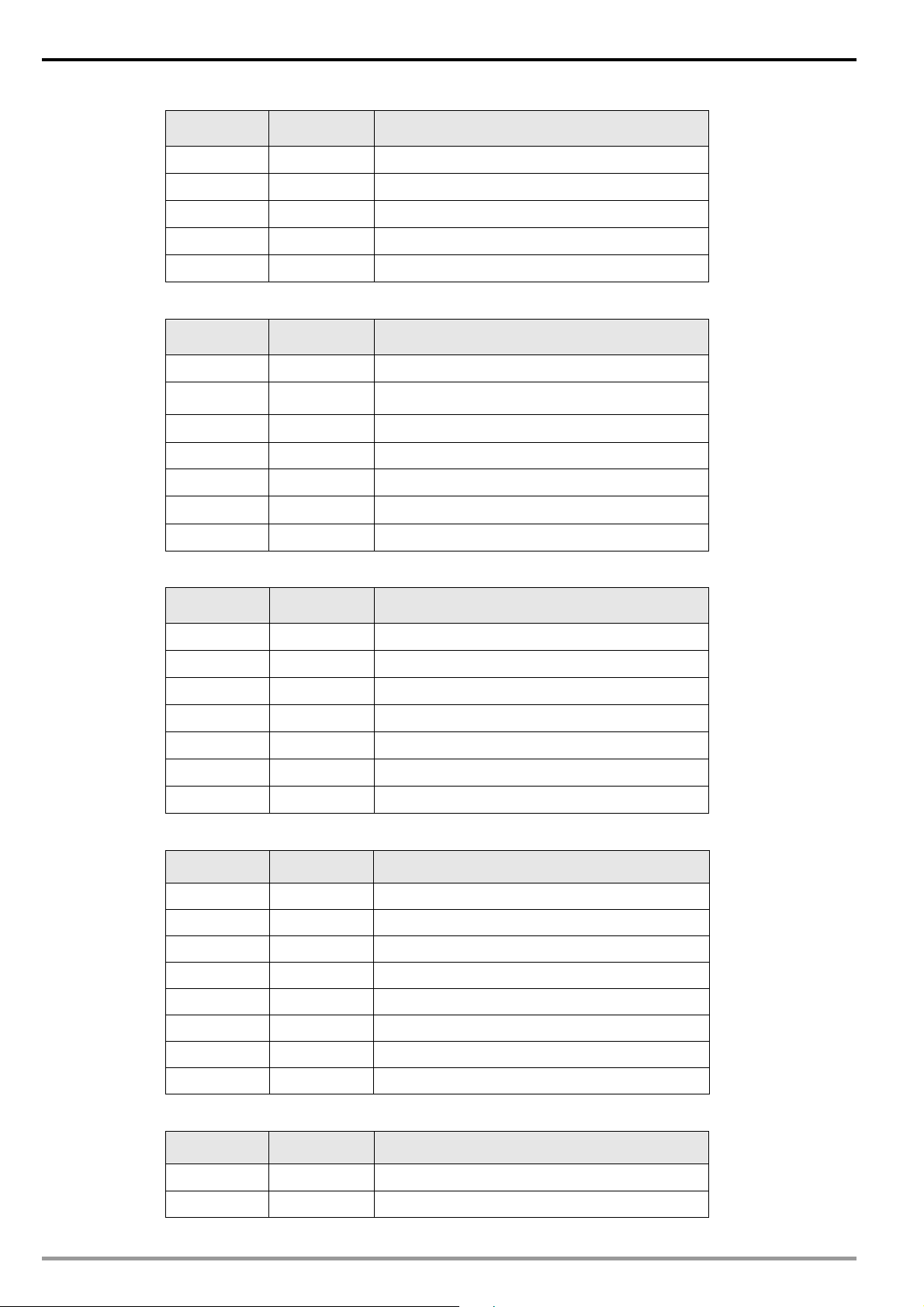
CANopen Slave Communication Module IFD9503
Sub-index
(hex)
3 0-02H Drive status
┊ ┊ ┊
F 0-14H Block data read/write register 5
10 0-15H Block data read/write register 6
11 0-16H Block data read/write register 7
Parameter No. Parameter funcion
z Main index: H’2001-----basic parameters
Sub-index
(hex)
1 1-00H Setting up external pulse input type
2 1-01H
3 1-02H Setting up speed and torque limit
┊ ┊ ┊
37 1-54H Position completed width bits
38 1-55H
39 1-56H
Parameter No. Parameter funcion
Setting up control mode and input source of control
instruction
Maximum speed limit
Output overload warning
z Main index: H’2002-----extension parameters
Sub-index
(hex)
1 2-00H Proportional position loop gain
2 2-01H Position loop gain switching rate
3 2-02H Position feed forward gain
┊ ┊ ┊
3F 2-63H Electronic gear ratio
40 2-64H Setting up proportion value setting
41 2-65H Torque limit mixed mode
Parameter No. Parameter funcion
z Main index: H’2003-----communication parameters
Sub-index
(hex)
1 3-00H Setting up communication address
2 3-01H Communication speed
3 3-02H Communication protocol
4 3-03H Transmission error treatment
5 3-04H Communication time-out detection
6 3-05H Selecting communication port
Parameter No. Parameter funcion
46
7 3-06H Communication control on digital input contact
8 3-07H Communication feedback delay time
z Main index: H’2004-----diagnosis parameters
Sub-index
(hex)
1 4-00H Recording error
2 4-01H Recording error
Parameter No. Parameter funcion
DVP-PLC Application Manual
Page 49

CANopen Slave Communication Module IFD9503
Sub-index
(hex)
3 4-02H Recording error
┊ ┊ ┊
16 4-21H Analog monitor output drift adjustment (ch2)
17 4-22H Anal og speed input drift value
18 4-23H Analog torque input drift value
Parameter No. Parameter funcion
6. Parameter objects of Delta DVP series PLC in the object dictionay
z Main index: 3000H-----download area paramerters (D divice)
down → download start address
Sub-index
(hex)
1 H’1000+down D (down+0) word
2 H’1001+down D (down+1) word
3 H’1002+down D (down+2) word
┊ ┊ ┊
16 H’101D+down D (down+29) word
17 H’101E+down D (down+30) word
Parameter address Parameter funcion Parameter type
word
18 H’101F+down D (down+31) word
z Main index: H’3001-----upload area parameters (D device)
up → upload start address
Sub-index
(hex)
1 H’1000+ up D (up+0) word
2 H’1001+ up D (up +1) word
3 H’1002+ up D (up +2) word
┊ ┊ ┊
16 H’101D+ up D (up +29) word
17 H’101E+ up D (up +30) word
18 H’101F+ up D (up +31) word
Parameter address Parameter funcion Parameter type
z Main index: 3002H-----start adddress
Sub-index
(hex)
1 Download start address 0 word
2 Upload start address 256 (0100H) word
Parameter funcion Default value Parameter type
word
z Main index: H’3100 ~ H’3199-----step S
Index
(hex)
3100/01 H’0000 S0 bit
3100/02 H’0001 S1 bit
┊ ┊ ┊
3100/FE H’00FD S253 bit
3101/01 H’0100 S256 bit
DVP-PLC Application Manual
Parameter address Parameter funcion Parameter type
bit
47
Page 50

CANopen Slave Communication Module IFD9503
Index
(hex)
3101/02 H’0101 S257 bit
┊ ┊ ┊
3101/FE H’01FD S509 bit
3102/01 H’0200 S512 bit
3102/02 H’0201 S513 bit
┊ ┊ ┊
Parameter address Parameter funcion Parameter type
z Main index: H’3200 ~ H’3299-----input point X
Index
(hex)
3200/01 H’0400 X0 bit
3200/02 H’0401 X1 bit
┊ ┊ ┊
3200/FE 04FDH X375 bit
Parameter address Parameter funcion Parameter type
z Main index: H’3300 ~ H’3399-----input point Y
Index
(hex)
3300/01 H’0500 Y0 bit
Parameter address Parameter funcion Parameter type
bit
bit
bit
3300/02 H’0501 Y1 bit
┊ ┊ ┊
3300/FE H’05FD Y375 bit
z Main index: H’3400 ~ H’3499-----timer T (bit device)
Index
(hex)
3400/01 H’0600 T0 bit
3400/02 H’060 T1 bit
┊ ┊ ┊
3400/FE H’06FD T253 bit
Parameter address Parameter funcion Parameter type
z Main index: H’3500 ~ H’3599-----timer T (word device)
Index
(hex)
3500/01 H’0600 T0 word
3500/02 H’0601 T1 word
┊ ┊ ┊
3500/FE H’06FD T253 word
Parameter address Parameter funcion Parameter type
z Main index: H’3600 ~ H’3699-----auxiliary relay M
bit
bit
word
48
Index
(hex)
3600/01 H’0800 M0 bit
3600/02 H’0801 M1 bit
┊ ┊ ┊
3600/FE H’08FD M253 bit
Parameter address Parameter funcion Parameter type
bit
DVP-PLC Application Manual
Page 51

CANopen Slave Communication Module IFD9503
Index
(hex)
3601/01 H’0900 M256 bit
3601/02 H’0901 M257 bit
┊ ┊ ┊
3601/FE H’09FD M509 bit
3602/01 H’0A00 M512 bit
3602/02 H’0A01 M513 bit
┊ ┊ ┊
Parameter address Parameter funcion Parameter type
z Main index: H’3700 ~ H’3799-----counter C (bit device)
Index
(hex)
3700/01 H’0E00 C0 bit
3700/02 H’0E01 C1 bit
┊ ┊ ┊
3700/FE H’0EFD C253 bit
Parameter address Parameter funcion Parameter type
z Main index: H’3800 ~ H’3899-----counter C (word device)
Index
(hex)
3800/01 H’0E00 C0 word
Parameter address Parameter funcion Parameter type
bit
bit
bit
3800/02 H’0E01 C1 word
┊ ┊ ┊
3800/C8 H’0EC7 C199 word
3800/C9 H’0EC8 C200 Dword
3800/CA H’0EC9 C201 Dword
┊ ┊ ┊
3800/FE H’0EFD C253 Dword
z Main index: H’3900 ~ H’3999-----register D
Index
(hex)
3900/01 H’1000 D0 word
3900/02 H’1001 D1 word
┊ ┊ ┊
3900/FE H’10FD D253 word
3901/01 H’1100 D256 word
3901/02 H’1101 D257 word
┊ ┊ ┊
Parameter address Parameter funcion Parameter type
word
word
word
word
3901/FE H’11FD D509 word
3902/01 H’1200 D512 word
3902/02 H’1201 D513 word
┊ ┊ ┊
7. Parameter objects of Delta DOP-A series HMI in yjr object dictionay
Virtual D parameters of IFD9503 arel listed as bellow:
DVP-PLC Application Manual
word
49
Page 52

CANopen Slave Communication Module IFD9503
z Main index: H’4000-----download area parameters
Sub-index
(hex)
Parameter address Parameter funcion Parameter type
1 H’1000 D0 word
2 H’1001 D1 word
3 H’1002 D2 word
┊ ┊ ┊
18 H’101D D29 word
19 H’101E D30 word
20 H’101F D31 word
z Main index: H’4001-----upload area parameters
Sub-index
(hex)
1 H’1020 D32 word
2 H’1021 D33 word
3 H’1022 D34 word
┊ ┊ ┊
18 H’103D D61 word
19 H’103E D62 word
Parameter No. Parameter funcion Parameter type
word
word
20 H’103F D63 word
8. Parameter objects of custom equipment in the object dictionay
z Main index: H’5000-----download area parameters
Sub-index
(hex)
1 1
2 2nd word of RxPDO 1
3 3rd word of RxPDO 1
4 4th word of RxPDO 1
5 1
6 2nd word of RxPDO 2
7 3rd word of RxPDO 2
8 4th word of RxPDO 2
9 1
A 2nd word of RxPDO 3
B 3rd word of RxPDO 3
C 4th word of RxPDO 3
D 1
E 2nd word of RxPDO 4
F 3rd word of RxPDO 4
Parameter funcion
st
word of RxPDO 1
st
word of RxPDO 2
st
word of RxPDO 3
st
word of RxPDO 4
50
10 4th word of RxPDO 4
11 1
st
word of RxPDO 5
12 2nd word of RxPDO 5
13 3rd word of RxPDO 5
DVP-PLC Application Manual
Page 53

CANopen Slave Communication Module IFD9503
Sub-index
(hex)
Parameter funcion
14 4th word of RxPDO 5
15 1
st
word of RxPDO 6
16 2nd word of RxPDO 6
17 3rd word of RxPDO 6
18 4th word of RxPDO 6
19 1
st
word of RxPDO 7
1A 2nd word of RxPDO 7
1B 3rd word of RxPDO 7
1C 4th word of RxPDO 7
1D 1
st
word of RxPDO 8
1E 2nd word of RxPDO 8
1F 3rd word of RxPDO 8
20 4th word of RxPDO 8
z Main index: H’5001-----upload area parameters
Sub-index
(hex)
1 1
Parameter funcion
st
word of TxPDO 1
2 2nd word of TxPDO 1
3 3rd word of TxPDO 1
4 4th word of TxPDO 1
5 1
st
word of TxPDO 2
6 2nd word of TxPDO 2
7 3rd word of TxPDO 2
8 4th word of TxPDO 2
9 1
st
word of TxPDO 3
A 2nd word of TxPDO 3
B 3rd word of TxPDO 3
C 4th word of TxPDO 3
D 1
st
word of TxPDO 4
E 2nd word of TxPDO 4
F 3rd word of TxPDO 4
10 4th word of TxPDO 4
11 1
st
word of TxPDO 5
12 2nd word of TxPDO 5
13 3rd word of TxPDO 5
14 4th word of TxPDO 5
15 1
16 2nd word of TxPDO 6
17 3rd word of TxPDO 6
18 4th word of TxPDO 6
DVP-PLC Application Manual
st
word of TxPDO 6
51
Page 54

CANopen Slave Communication Module IFD9503
2
_
2
Sub-index
(hex)
19 1
1A 2nd word of TxPDO 7
1B 3rd word of TxPDO 7
1C 4th word of TxPDO 7
1D 1
1E 2nd word of TxPDO 8
1F 3rd word of TxPDO 8
20 4th word of TxPDO 8
Parameter funcion
st
word of TxPDO 7
st
word of TxPDO 8
6 Connection of IFD9503 with Other Equipment
1. Communication wirings when connected to equipment through PORT1.
z When IFD9503 is connected to Delta VFD series AC motor drive:
By RS-485 communication; using standard cable with RJ-12 connectors is suggested.
IFD9503
RJ-12 (RS-485)
6
5
4
3
2
1
RJ-12 RJ-12
DATADATA+
(3)
(4)
VFD series AC motor drive
RJ-12 (RS-485)
6
5
(3)
(4)
DATA -
DATA+
4
3
2
1
z When IFD9503 is connected to Delta DVP series PLC:
By RS-485 communication
IFD9503
RJ-12 (RS-485)
6
5
4
3
2
1
RJ-1
DATA -
DATA +
(3)
(4)
DATADATA+
DVP-PLC
RS-485 wiring terminal
+
PLC COM2
z When IFD9503 is connected to Delta DTA/DTB series temperature controller:
By RS-485 communication
IFD9503
RJ-12 (RS-485)
6
5
4
3
2
1
RJ-1
DATADATA +
(3)
(4)
DATA -
DATA+
DTA/DTB
RS-485 wiring terminal
DATA +
DATA -
RS-485
52
DVP-PLC Application Manual
Page 55

CANopen Slave Communication Module IFD9503
r
z When IFD9503 is connected to Delta ASD-A series servo drive:
By RS-485 communication
IFD9503
RJ-12 (RS-485)
6
5
4
3
2
1
RJ-12
DATA+
DATA-
(4)
(3)
CN3 conncetor (RS-485)
(3) 485+
(5) 485+
(4) 485(6) 485-
ASD-A
35
1
2
46
CN3 connecto
z When IFD9503 is connected to Delta DOP series human machine interface:
By RS-485 communication
IFD9503
RJ-12 (RS-485)
6
5
4
3
2
1
RJ-12
DATA+
DATA -
(4)
(3)
(2) 48 5+
(3) 48 5+
(1) 485-
(4) 48 5-
DOP
DB9 male (RS-485)
5
9
4
8
3
7
2
6
1
DOP COM2
2. Communication wirings when connected to equipment through PORT2.
z When IFD9503 is connected to Delta VFD series AC motor drive:
By RS-485 communication
IFD9503
DB9 female (RS-485)
5
9
4
8
3
7
2
6
1
DATA-
DATA+
DB9 female
(3)
(8)
(3)
(4)
VFD series AC motor drive
RJ-12 (RS-485)
6
DATADATA+
5
4
3
2
1
RJ-12
z When IFD9503 is connected to Delta DVP series PLC:
By RS-232 communication; using standard DVPACAB215/DVPACAB230 is suggested.
IFD9503
DB9 female (RS-232)
5
9
4
8
3
7
2
6
1
RXD
TXD
GND
(2)
(3)
(5)
8 pin Mini DIN male (RS-232)
(5)
TX
(4)
RX
(8)
GND
DVP-PLC
2
4
5
8
7
1
3
6
By RS-485 communication
DVP-PLC Application Manual
DB9 female
53
Page 56

CANopen Slave Communication Module IFD9503
_
IFD9503
DB9 female (RS-485)
5
9
4
8
3
7
2
6
1
DB9 female
DATADATA +
(3)
(8)
DATA-
DATA+
DVP-PLC RS-485
wiring terminal (RS-485)
+
PLC COM2
z When IFD9503 is connected to Delta DTA/DTB series temperature controller:
By RS-485 communication
IFD9503
DB9 female (RS-485)
5
9
4
8
3
7
2
6
1
DB9 female
DATA DATA+
(3)
(8)
RS-485 wiring terminal (RS-485)
DATA -
DATA+
DTA/DTB
DATA+
DATA-
RS-48 5
z When IFD9503 is connected to Delta ASD-A servo drive:
By RS-232 communication
IFD9503
DB9 female (RS-232)
5
9
4
8
3
7
2
6
1
DB9 female
RXD
TXD
GND
(2)
(3)
(5)
(2)
(4)
(1)
CN3 connector (RS-232)
TX
RX
GND
RS-485 communication
IFD9503
DB9 female (RS-485)
5
9
4
8
3
7
2
6
1
DATA +
DATA-
DB9 female
(8)
(3)
(3) 48 5+
(5) 48 5+
(4) 485(6) 48 5-
CN3 connector (RS-485)
ASDA
35
1
2
46
CN3 connector
ASDA
CN3 connector
35
1
2
46
CN3 connector
54
DVP-PLC Application Manual
Page 57
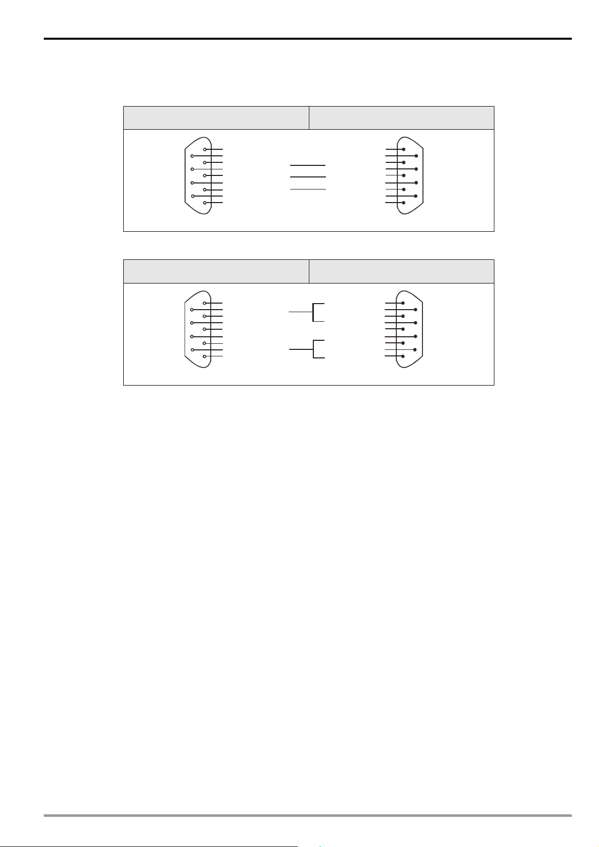
CANopen Slave Communication Module IFD9503
z When IFD9503 is connected to Delta DOP series human machine interface:
By RS-232 communication
IFD9503
DB9 female (RS-232)
5
9
4
8
3
7
2
6
1
DB9 female
RXD
TXD
GND
(2)
(3)
(5)
(3)
TX
(2)
RX
(5)GND
DOP
DB9 male (RS-232)
5
9
4
8
3
7
2
6
1
DOP COM1
By RS-485 communication
IFD9503
DB9 female (RS-485)
5
9
4
8
3
7
2
6
1
DATA+
DATA-
(8)
(3)
(2) 48 5+
(3) 48 5+
(1) 485-
(4) 48 5-
DB9 female
DOP
DB9 male (RS-485)
5
9
4
8
3
7
2
6
1
DOP COM2
DVP-PLC Application Manual
55
 Loading...