

Page 1

Installation instructions
Hybrid E5 Battery Storage System
EuropeUnited Kingdom
Page 2

The Delta manuals undergo continuous revision in order
to provide you with complete information regarding the
installation and operation of our inverters. Therefore,
before starting installation work, always consult www.
solar-inverter.com to check whether a newer version of the
Quick Installation Guide or of the comprehensive Installation and Operation Manual is available.
© Copyright – Delta Electronics (Netherlands) B.V. – All
rights reserved.
This manual is intended for installers.
The information in this manual is to be treated as condential and no part of this manual may be reproduced without
prior written permission from Delta Electronics. The information in this manual may not be used for any purpose not
directly connected to the use of the inverter.
All information and specications can be modied without
prior notice.
All translations of this manual not authorized by Delta
Electronics (Netherlands) B.V. must include the annotation:
"Translation of the original operation manual".
Delta Electronics (Netherlands) B.V.
Tscheulinstraße 21
79331 Teningen
Germany
Authorized representative for this product in the EU:
Delta Electronics (Netherlands) B.V.
Zandsteen 15
2132 MZ Hoofddorp
Netherlands
2
Installation Instructions for the Hybrid E5 Battery Storage System EU V1 EN 2018-09-17
Page 3

Table of Contents
Basic safety instructions. . . . . . . . . . . . . . . . . . . . . . . . . . . . . . . . . . . . . . . . . . . . . . . . . . . . . . . . .4
Inverter . . . . . . . . . . . . . . . . . . . . . . . . . . . . . . . . . . . . . . . . . . . . . . . . . . . . . . . . . . . . . . . . .4
Battery box . . . . . . . . . . . . . . . . . . . . . . . . . . . . . . . . . . . . . . . . . . . . . . . . . . . . . . . . . . . . . . . 5
System overview . . . . . . . . . . . . . . . . . . . . . . . . . . . . . . . . . . . . . . . . . . . . . . . . . . . . . . . . . . . . . 6
Scope of supply. . . . . . . . . . . . . . . . . . . . . . . . . . . . . . . . . . . . . . . . . . . . . . . . . . . . . . . . . . . . . . 8
Inverter . . . . . . . . . . . . . . . . . . . . . . . . . . . . . . . . . . . . . . . . . . . . . . . . . . . . . . . . . . . . . . . . .8
Battery box . . . . . . . . . . . . . . . . . . . . . . . . . . . . . . . . . . . . . . . . . . . . . . . . . . . . . . . . . . . . . . . 8
Power meter: P1E or P3E . . . . . . . . . . . . . . . . . . . . . . . . . . . . . . . . . . . . . . . . . . . . . . . . . . . . . . . 9
R4E Smart Monitor . . . . . . . . . . . . . . . . . . . . . . . . . . . . . . . . . . . . . . . . . . . . . . . . . . . . . . . . . . .9
Components of the system . . . . . . . . . . . . . . . . . . . . . . . . . . . . . . . . . . . . . . . . . . . . . . . . . . . . . . 10
Inverter . . . . . . . . . . . . . . . . . . . . . . . . . . . . . . . . . . . . . . . . . . . . . . . . . . . . . . . . . . . . . . . . 10
Battery box . . . . . . . . . . . . . . . . . . . . . . . . . . . . . . . . . . . . . . . . . . . . . . . . . . . . . . . . . . . . . . 12
Power meter . . . . . . . . . . . . . . . . . . . . . . . . . . . . . . . . . . . . . . . . . . . . . . . . . . . . . . . . . . . . . 14
Smart Monitor . . . . . . . . . . . . . . . . . . . . . . . . . . . . . . . . . . . . . . . . . . . . . . . . . . . . . . . . . . . . 15
Planning the installation . . . . . . . . . . . . . . . . . . . . . . . . . . . . . . . . . . . . . . . . . . . . . . . . . . . . . . . . 16
Inverter installation location . . . . . . . . . . . . . . . . . . . . . . . . . . . . . . . . . . . . . . . . . . . . . . . . . . . . . 16
Battery box installation location . . . . . . . . . . . . . . . . . . . . . . . . . . . . . . . . . . . . . . . . . . . . . . . . . . . 17
Circuit diagram for 1-phase grids. . . . . . . . . . . . . . . . . . . . . . . . . . . . . . . . . . . . . . . . . . . . . . . . . . . 18
Circuit diagram for 3-phase grids. . . . . . . . . . . . . . . . . . . . . . . . . . . . . . . . . . . . . . . . . . . . . . . . . . . 20
Dimensions . . . . . . . . . . . . . . . . . . . . . . . . . . . . . . . . . . . . . . . . . . . . . . . . . . . . . . . . . . . . . . . 22
Inverter . . . . . . . . . . . . . . . . . . . . . . . . . . . . . . . . . . . . . . . . . . . . . . . . . . . . . . . . . . . . . . . . 22
Battery box . . . . . . . . . . . . . . . . . . . . . . . . . . . . . . . . . . . . . . . . . . . . . . . . . . . . . . . . . . . . . . 23
Power meter and Smart Monitor . . . . . . . . . . . . . . . . . . . . . . . . . . . . . . . . . . . . . . . . . . . . . . . . . . . 24
Mounting . . . . . . . . . . . . . . . . . . . . . . . . . . . . . . . . . . . . . . . . . . . . . . . . . . . . . . . . . . . . . . . . 25
Inverter . . . . . . . . . . . . . . . . . . . . . . . . . . . . . . . . . . . . . . . . . . . . . . . . . . . . . . . . . . . . . . . . 25
Battery box - Floor mounting . . . . . . . . . . . . . . . . . . . . . . . . . . . . . . . . . . . . . . . . . . . . . . . . . . . . . 28
Battery box - Wall mounting . . . . . . . . . . . . . . . . . . . . . . . . . . . . . . . . . . . . . . . . . . . . . . . . . . . . . 30
R4E Smart Monitor . . . . . . . . . . . . . . . . . . . . . . . . . . . . . . . . . . . . . . . . . . . . . . . . . . . . . . . . . . 33
P1E and P3E Power meter. . . . . . . . . . . . . . . . . . . . . . . . . . . . . . . . . . . . . . . . . . . . . . . . . . . . . . 34
Connect inverter to battery box . . . . . . . . . . . . . . . . . . . . . . . . . . . . . . . . . . . . . . . . . . . . . . . . . . . . 35
Readying charging cables for use and connecting them . . . . . . . . . . . . . . . . . . . . . . . . . . . . . . . . . . . . . . . 35
Readying CANBUS cable for use and connecting it . . . . . . . . . . . . . . . . . . . . . . . . . . . . . . . . . . . . . . . . . 38
Connect the communication card of the inverter. . . . . . . . . . . . . . . . . . . . . . . . . . . . . . . . . . . . . . . . . . . 39
Overview . . . . . . . . . . . . . . . . . . . . . . . . . . . . . . . . . . . . . . . . . . . . . . . . . . . . . . . . . . . . . . . 39
Connecting the communications cable . . . . . . . . . . . . . . . . . . . . . . . . . . . . . . . . . . . . . . . . . . . . . . . . 41
Connecting inverter and Smart Monitor via RS485. . . . . . . . . . . . . . . . . . . . . . . . . . . . . . . . . . . . . . . . . . 43
Connecting inverter and power meter via RS485. . . . . . . . . . . . . . . . . . . . . . . . . . . . . . . . . . . . . . . . . . . 44
Connecting the inverter to the mains (AC) . . . . . . . . . . . . . . . . . . . . . . . . . . . . . . . . . . . . . . . . . . . . . . 45
General information . . . . . . . . . . . . . . . . . . . . . . . . . . . . . . . . . . . . . . . . . . . . . . . . . . . . . . . . . 45
Readying AC cable for use and connecting it . . . . . . . . . . . . . . . . . . . . . . . . . . . . . . . . . . . . . . . . . . . . 46
Connecting CT cable of the power meter . . . . . . . . . . . . . . . . . . . . . . . . . . . . . . . . . . . . . . . . . . . . . . . 49
Connecting the inverter to solar modules (DC). . . . . . . . . . . . . . . . . . . . . . . . . . . . . . . . . . . . . . . . . . . . 51
Commissioning . . . . . . . . . . . . . . . . . . . . . . . . . . . . . . . . . . . . . . . . . . . . . . . . . . . . . . . . . . . . . 53
Technical specications . . . . . . . . . . . . . . . . . . . . . . . . . . . . . . . . . . . . . . . . . . . . . . . . . . . . . . . . 54
Inverter . . . . . . . . . . . . . . . . . . . . . . . . . . . . . . . . . . . . . . . . . . . . . . . . . . . . . . . . . . . . . . . . 54
Battery box . . . . . . . . . . . . . . . . . . . . . . . . . . . . . . . . . . . . . . . . . . . . . . . . . . . . . . . . . . . . . . 56
Power meter, Smart Monitor . . . . . . . . . . . . . . . . . . . . . . . . . . . . . . . . . . . . . . . . . . . . . . . . . . . . . 57
Customer Service - Europe . . . . . . . . . . . . . . . . . . . . . . . . . . . . . . . . . . . . . . . . . . . . . . . . . . . . . . 60
Installation Instructions for the Hybrid E5 Battery Storage System EU V1 EN 2018-09-17
3
Page 4
Basic safety instructions
Inverter
DANGER
Electric shock
Potentially fatal voltages are present at the
inverter during operation. When the inverter
is disconnected from all power sources, this
voltage remains in the inverter for up to 60
seconds.
Therefore, always carry out the following
steps before working on the inverter:
1. Turn the AC/DC disconnector to the OFF
position.
2. Disconnect the inverter from all AC and
DC voltage sources and make sure that
none of the connections can be accidentally restored.
3. Wait at least 60 seconds until the internal
capacitors have discharged.
DANGER
Electric shock
Potentially fatal voltages are present at the inverter DC connections. When light falls on the
solar modules, they immediately start to generate electricity. This also happens when light
does not fall directly on the solar modules.
► Never disconnect the inverter from the
solar modules when it is under load.
► Turn the AC/DC disconnector to the OFF
position.
► Disconnect the connection to the mains so
that the inverter cannot supply energy to
the mains.
► Disconnect the inverter from all AC and
DC voltage sources. Ensure that none of
the connections can be restored accidentally.
► Ensure that the DC cables cannot be
touched accidentally.
● Warning instructions and warning symbols attached
to the inverter by Delta Electronics must not be removed.
● The inverter has a high leakage current value. The
grounding cable must be connected before commencing operation.
● Do not disconnect any cables while the inverter is
under load due to risk of a fault arc.
● To prevent damage due to lightning strikes, follow the
provisions that apply in your country.
● The surface of the inverter can get very hot during
operation. Wear safety gloves when you touch the
inverter (apart from at the display).
● Only equipment in accordance with SELV (EN 60950)
may be connected to the RS485 interfaces.
● All connections must be sufciently insulated in order
to ensure the IP65 degree of protection. Unused connections must be closed using cover caps.
● To comply with the IEC 62109-5.3.3 safety require-
ments and avoid injury or material damage, the
inverter must be installed and operated in accordance
with the safety and operating instructions set out in
this manual. Delta Electronics is not responsible for
damage resulting from failure to follow the safety and
operating instructions set out in this manual.
● The inverter may be installed and commissioned only
by installers who have been trained and certied for
the installation and operation of mains-based solar
inverters.
● All repair work on the inverter must be carried out
by Delta Electronics. Otherwise, the warranty will be
void.
4
Installation Instructions for the Hybrid E5 Battery Storage System EU V1 EN 2018-09-17
Page 5
Basic safety instructions
Battery box
DANGER
Explosive gases
Explosive gases may escape from the battery.
► Protect the battery box and its surround-
ings from open re, embers and ying
sparks.
► Set up the battery box at a sufcient dis-
tance from heat sources and ammable
materials.
► Install, operate and maintain the battery
box according to the instructions of the battery manufacturer.
► Follow the battery manufacturer's instruc-
tions with regard to the storage and operating temperature range of the battery.
► The installation location must be protected
from ooding.
► Sufciently ventilate the area in which the
battery box is located.
WARNING
Corrosive and toxic electrolyte
The batteries contain an electrolyte that can
be corrosive and toxic in contact with eyes, respiratory organs and skin. Blinding or serious
chemical burns may result.
► Install, operate and maintain the battery
box according to the instructions of the battery manufacturer.
► Follow the battery manufacturer's instruc-
tions with regard to the storage and operating temperature range of the battery.
► Sufciently ventilate the area in which the
battery box is located.
► Protect the battery box and battery from
damage.
► Never open the battery box.
► If contact with acid spray occurs, imme-
diately and thoroughly ush the affected
body area with clear water, then obtain
medical attention.
► If acid vapors are inhaled, immediately
obtain medical attention.
● All repair work on the battery box must be performed
by Delta Electronics or installers certied by Delta
Electronics; otherwise the warranty is voided.
● Warning instructions and warning symbols attached
to the battery box by Delta Electronics must not be
removed.
● Do not disconnect any cables while the battery box is
under load due to risk of a fault arc.
● To prevent damage due to lightning strikes, follow the
regulations that apply in your country or region.
● All connections must be sufciently insulated in order
to ensure the IP55 degree of protection. Seal any
unused connection openings with the closure caps
supplied.
● The battery box may be installed and commissioned
only by installers who have been trained and certied
for the installation and operation of battery storage
systems.
● Please observe the user information supplied with the
battery.
● The battery box must always be replaced in its en-
tirety. Separate replacement of the battery alone is
not intended or allowed.
Installation Instructions for the Hybrid E5 Battery Storage System EU V1 EN 2018-09-17
5
Page 6
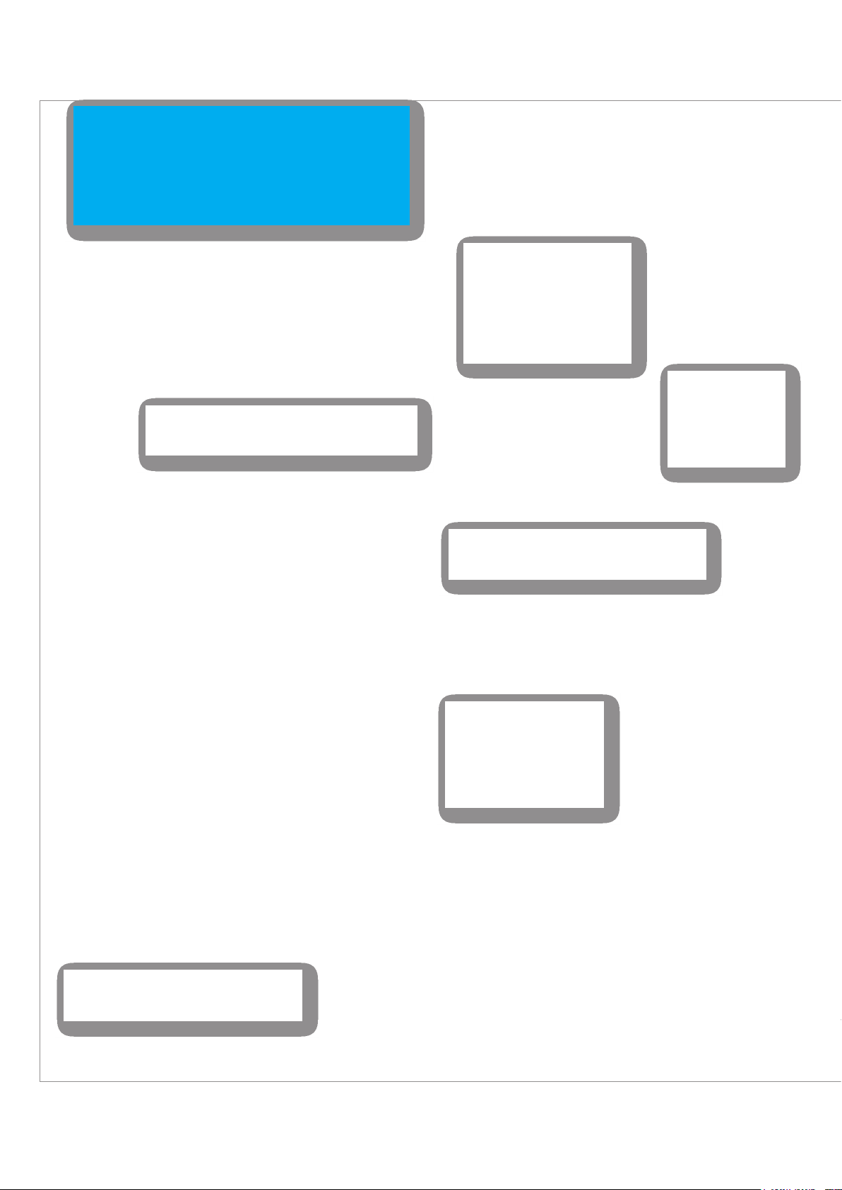
System overview
L1
Washing machine
In the standard case, i.e., when mains power is available
and the sun is shining, all consumers in the house –
including the three-phase ones – are supplied via the
mains, the solar module or the batteries. If the mains
have failed and solar energy is not available, solely the
consumers connected to L’ of the inverter will be
supplied.
DC String 1
TV
Lights
L1’
The plug connector for the television is connected to
L2 and in the event of mains failure is not supplied if
energy is only available from the batteries.
L2
The inverter has a separate
MPP tracker for each of the
two DC inputs (DC1 and
DC2). Either 2 separate DC
strings or a single DC string
can be connected to the DC
inputs.
All devices connected to L’ of the inverter are
supplied with power from the batteries in the
event of mains failure.
L’
DC String 2
The inverter forms
the heart of the
system. All important
information can be
read off the display.
Fish tank
If the Smart Monitor is connected to the router,
the Hybrid E5 System can be monitored and
configured from a laptop.
In this example, the lights,
fish tank and freezer are
connected to L’ of the inverter
and will be supplied with
battery power if necessary;
such as during an emergency.
Freezer
L’
6
Installation Instructions for the Hybrid E5 Battery Storage System EU V1 EN 2018-09-17
Page 7
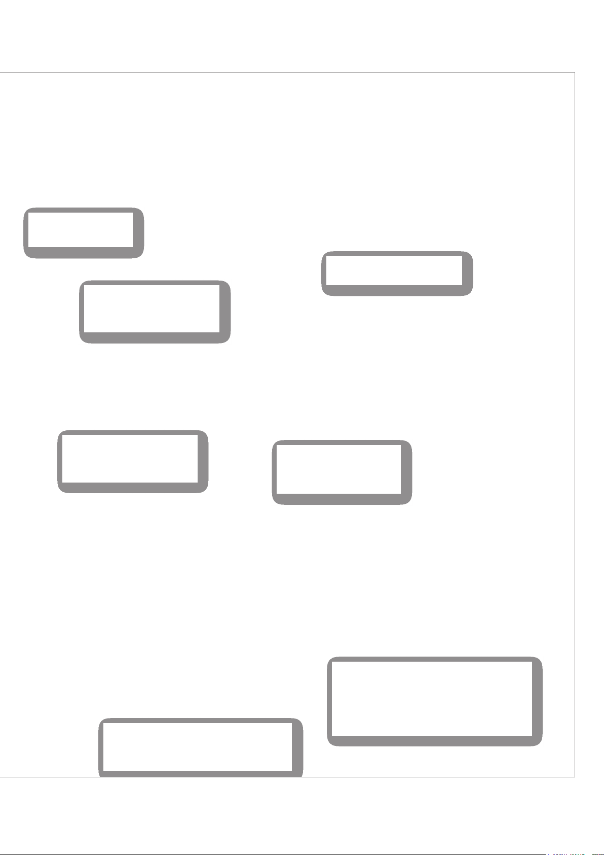
Washing machine
In this example, the
inverter is connected to the
L1 phase.
E5 Inverter
System overview
System overview
Hybrid E5 Battery Storage System
for use with three-phase mains
L3 PE
L1 L2
N
The current clamps measure
current and voltage in each phase.
The Smart Monitor assists with
setup and monitoring of the system
and is connected to the inverter via
RS485.
Smart Monitor
Router
If the Smart Monitor is connected to
a router, the system can be
monitored from a PC.
Battery box 1
Current
meter
The current meter records the
measured data supplied by the
current clamps and sends the
data to the inverter.
Battery box 2
(optional)
1 Current clamp
Per phase
Electronic
household meter
House connection box
To mains
L1
The plug connector for the washing machine is
connected directly to L1. If mains power is
present, current is supplied to the plug connector. In the event of mains failure, the plug
Installation Instructions for the Hybrid E5 Battery Storage System EU V1 EN 2018-09-17
In normal operation, the batteries are charged via the
solar modules. Power is only ever supplied to the
batteries via the mains to perform a maintenance
charge, if necessary.
Upon interruption of the mains supply, the Hybrid E5
System switches to battery supply power, thereby
preventing critical electrical equipment from shutting
7
Page 8
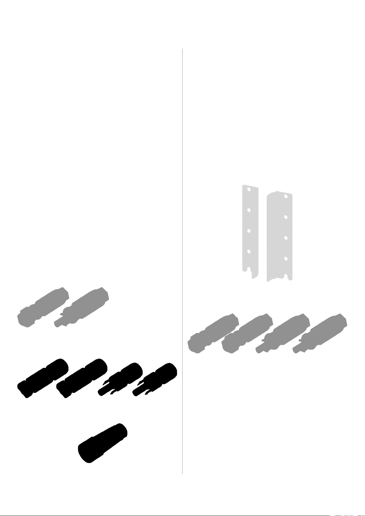
Scope of supply
Inverter
Inverter
Battery box
Battery box
Mounting plate
Plug for DC connection between
inverter and battery box
MC4 plug for connecting the solar module,
2x DC positive, 2 x DC negative
2 mounting angles (left/right) for fastening to the wall
IP65 plug for communica-
tion cable between inverter
and battery box
Plug for DC connection between inverter and battery box, 2x DC positive,
2 x DC negative, type: Phoenix Contact ???
IP65 plug for communication cable
between inverter and battery box
AC plug
8
Installation Instructions for the Hybrid E5 Battery Storage System EU V1 EN 2018-09-17
Page 9
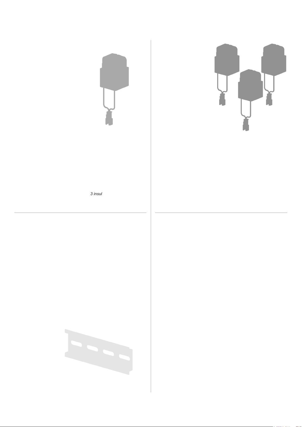
Scope of supply
Power meter: P1E or P3E
Scope of supply, P1E only Scope of supply, P3E only
1 single-phase power meter (to be
afxed to DIN rail)
1 current clamp
1 three-phase power meter (to be
afxed to DIN rails)
R4E Smart Monitor
3 current clamps
3 insulated cable lugs
1 x sensor cable for 1 current
clamp (2 m)
1 x sensor cable for 3 current
clamps (2 m)
Scope of supply P1E and P3E R4E Smart Monitor
2 stoppers for power meter (to be
afxed to DIN rails)
Power supply (not suitable for Germany).
Power is supplied via the inverter.
5 insulated cable lugs
1 plug for RS485
connection
Installation Instructions for the Hybrid E5 Battery Storage System EU V1 EN 2018-09-17
1 DIN rail, 12.5 cm (incl. 2 screws for wall
mounting)
2 mounting screws for fas-
tening to the wall
9
Page 10
Components of the system
Inverter
Overview
1
2
3
1 Display, buttons, and LED
2 Electrical connections
3 Type plate
Electrical connections
1
2
3 4 6 7 85
1 AC/DC disconnector 5 Battery communication (CANBUS)
2 Connection for solar modules 6 Communication connection (RS485, digital inputs,
external power-off)
3 Connection for battery 7 Mains connection
4 Switch on the Hybrid E5 System when no external
8 Bypass switch
power is supplied via the mains. Energy from the
solar modules is used to start up the system.
10
Installation Instructions for the Hybrid E5 Battery Storage System EU V1 EN 2018-09-17
Page 11

Components of the system
Inverter
Display, buttons, and LEDs
Label Designation Use
LEDs
Grid Mains Green LED; lights up when the inverter is supplying power to the mains.
AlArm Alarm Red LED; displays a warning, an error or a fault.
Buttons
Exit
Down
Up
Enter
LED status messages
Grid AlArm Meaning
Flashes Off Inverter starts; inverter is in Standalone mode
On Off Inverter is in normal operating mode
Off On Warning, fault or failure. A corresponding message is shown on the display.
Off Off
Flashes Flashes Inverter is in Bootloader mode.
Exit the current menu.
Cancel the setting for a parameter. Changes are not applied.
Move downwards in the menu.
Reduce the value of a congurable parameter.
Move upwards in the menu.
Increase the value of a congurable parameter.
Select menu item.
Open a congurable parameter for editing.
Cancel the setting for a parameter. Changes are adopted.
The inverter is switched off = The AC/DC disconnecter is in the OFF position.
Installation Instructions for the Hybrid E5 Battery Storage System EU V1 EN 2018-09-17
11
Page 12

Components of the system
Battery box
Overview
Linke Seite
(Batterieeingang)
Rechte Seite
(Batterieausgang)
Electrical connections
2 3 41
6 75
1 BATTERY + Positive charging cable for inverter 5 COMM. Communication connection (CAN-
BUS)
2 BATTERY – Negative charging cable for inverter 6 BATTERY – Positive charging cable for next bat-
tery box
3 COMM. Communication connection (CAN-
BUS)
7 BATTERY + Negative charging cable for next bat-
tery box
4 STANDALONE Switch on the Hybrid E5 System
when no external power is supplied
via the mains. Energy from the battery is used to start up the system.
12
Installation Instructions for the Hybrid E5 Battery Storage System EU V1 EN 2018-09-17
Page 13

LEDs
Label Designation Use
Red LED. Indicates an error or warning.
Components of the system
Battery box
FAult Error
StAndby / On Standby / On
ChArGe / diSChArGe Charge / Discharge
Additional LED status messages
All three LEDs blink Update rmware
All three LEDs are continuously illuminated Communication error
Blinking: Warning
Continuous light: Error
Green LED
Blinking: Standby Mode
Continuous light: Normal operating mode
Yellow LED
Blinking: Battery is currently charging
Continuous light: Battery is currently discharging
Installation Instructions for the Hybrid E5 Battery Storage System EU V1 EN 2018-09-17
13
Page 14

Components of the system
Power meter
1 12
5
4
3
5
P1E P3E
1 AC cable connection
2 Current clamp(s) connection
3 Reset button
4 RS485 cable connection and RS485 termination resistor
5 Status LED
3
2
4
14
Installation Instructions for the Hybrid E5 Battery Storage System EU V1 EN 2018-09-17
Page 15

Components of the system
Smart Monitor
1
2
1 USB Connection 1
2 USB Connection 2
3 LANA connection (RJ45)
4 Communication connection (CAN, RS485, +12 V sup-
ply voltage)
5 Connection for external power supply (not included in
the scope of delivery. Voltage is supplied via RS485.)
3
4
5
Installation Instructions for the Hybrid E5 Battery Storage System EU V1 EN 2018-09-17
15
Page 16
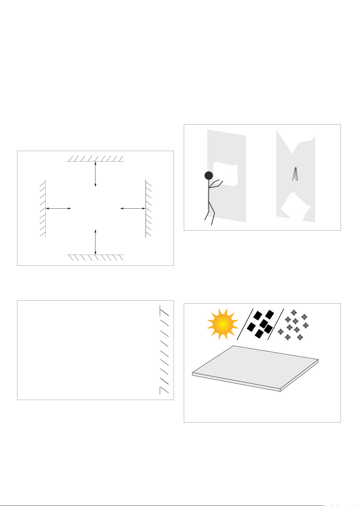
Planning the installation
Inverter installation location
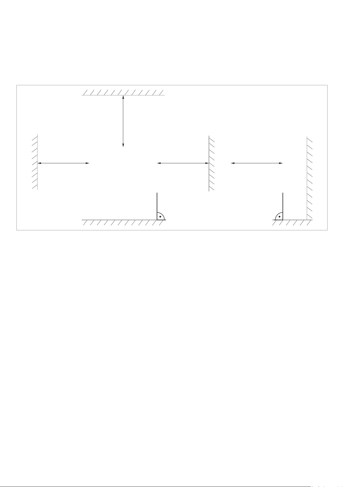
Installation clearances and air circulation
► Ensure sufcient air circulation. Warm air must be
able to escape from below. Leave enough space
around the inverter.
► Note the Operating temperature range without derat-
ing and the Operating temperature range.
When the Operating temperature range without derat-
ing is exceeded the inverter reduces the AC power
fed into the mains.
When the Operating temperature range is exceeded,
the inverter stops feeding AC power into the mains.
This is normal operating behavior for the inverter and
is necessary to protect the internal electronics.
>20 cm>20 cm
>20 cm>20 cm
► Use mounting materials (dowels, screws etc.) that are
suitable for the wall or the mounting system, as well
as the heavy weight of the inverter.
► Mount the inverter on a vibration-free wall to avoid
disruptions.
► When using the inverter in residential areas or in
buildings with animals, possible noise emissions can
be disturbing. Therefore, carefully choose the place of
installation.
► Mount the inverter on a reproof wall.
Mounting alignment
► Mount the inverter vertically.
Installation location of the inverter
► Attach the inverter so that the information on the
display can be read and the buttons can be operated
without any problems.
► The inverter is heavy. The wall has to be able to bear
the heavy weight of the inverter.
► Always use the mounting plate supplied with the
inverter.
Outdoor installations
► Indoor installation is generally preferable. The inverter
has a protection rating of IP65 and can therefore
be outdoors as well. When installed outdoors, the
inverter should nevertheless be protected by a roof
against direct solar irradiation, rain and snow, in order
to ensure sufcient air circulation.
16
Installation Instructions for the Hybrid E5 Battery Storage System EU V1 EN 2018-09-17
Page 17
Installation clearances and air circulation
► Ensure sufcient air circulation. Hot air must be able
to dissipate upwards. Leave enough space around
the battery box.
► Note the operating temperature range.
>100 cm
>100 cm >100 cm >100 cm
Planning the installation
Battery box installation location
Installation Instructions for the Hybrid E5 Battery Storage System EU V1 EN 2018-09-17
17
Page 18
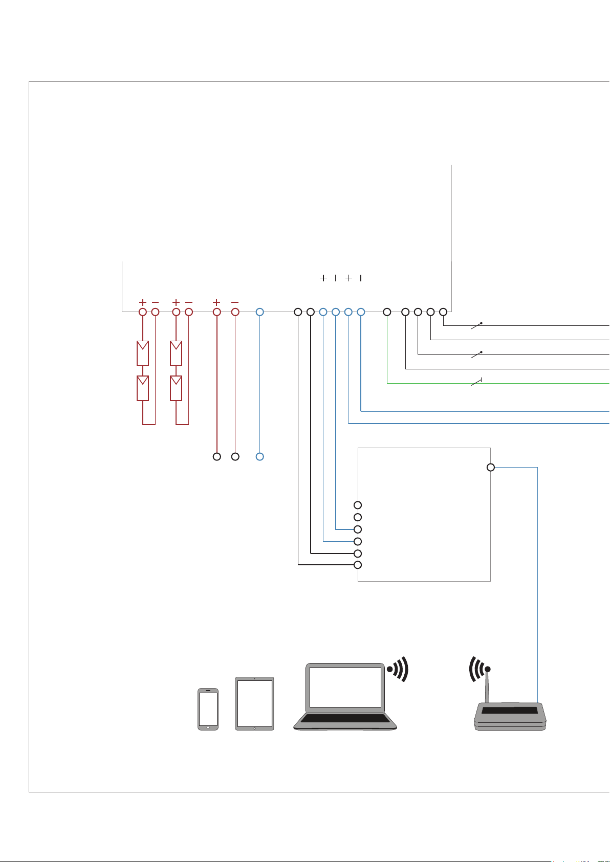
Planning the installation
Electrical consumers to be
supplied via batteries or solar
modules in the event of
mains failure should connect
to L’ and N’ of the inverter.
L’: 28 A max. (Stand Alone mode: 15.7 A max.)
Circuit diagram for 1-phase grids
Inverter
Module strings
Battery box
BT CANDC2DC1
DATA
GND
VCC
DATA
DATA
DATA
CAN-L
CAN-H
485-B (–)
485-A (+)
GND
+12V
PE
N’L’NL
LAN
18
Smart Monitor
Router
Installation Instructions for the Hybrid E5 Battery Storage System EU V1 EN 2018-09-17
Page 19

Electrical consumers to be
supplied via batteries or solar
modules in the event of
mains failure should connect
to L’ and N’ of the inverter.
Planning the installation
Circuit diagram for 1-phase grids
L: 28 A max.
N L
LN
kWh
TERM.
485 B (–)
485 A (+)
485 B (–)
485 A (+)
Meter cabinet
Installation Instructions for the Hybrid E5 Battery Storage System EU V1 EN 2018-09-17
CT
N
L1
PE
19
Page 20

L’: 28 A max. (Stand Alone mode: 15.7 A max.)
Electrical consumers to be
supplied via batteries or solar
modules in the event of
mains failure should connect
to L’ and N’ of the inverter.
Planning the installation
Circuit diagram for 3-phase grids
Inverter
Module strings
Battery box
BT CANDC2DC1
DATA
GND
VCC
DATA
DATA
DATA
CAN-L
CAN-H
485-B (–)
485-A (+)
GND
+12V
PE
N’L’NL
LAN
20
Smart Monitor
Router
Installation Instructions for the Hybrid E5 Battery Storage System EU V1 EN 2018-09-17
Page 21

Electrical consumers to be
supplied via batteries or solar
modules in the event of
mains failure should connect
to L’ and N’ of the inverter.
Planning the installation
Circuit diagram for 3-phase grids
All other electrical consumers
can be connected to any given
phase.
L: 28 A max.
L1 L2 L3
N
L3L2L1N
kWh
TERM.
485 B (–)
485 A (+)
485 B (–)
485 A (+)
Installation Instructions for the Hybrid E5 Battery Storage System EU V1 EN 2018-09-17
N
L1
CT
L2
L3
PE
Meter cabinet
21
Page 22

Dimensions
Inverter
510 77
168
445
327
302
20
424
330
110
35
60
440
458
Inverter and mounting plate dimensions
22
Installation Instructions for the Hybrid E5 Battery Storage System EU V1 EN 2018-09-17
Page 23

Dimensions
Battery box
552
Battery box dimensions: General dimensions
200
596
504
∅13
Battery box dimensions: Drilling dimensions for oor mounting
657
617
∅11
207
20
120
40
437 437
377
317
257
Battery box dimensions: Drilling dimensions for wall mounting
Installation Instructions for the Hybrid E5 Battery Storage System EU V1 EN 2018-09-17
23
Page 24

Dimensions
Power meter and Smart Monitor
63,3
47,3
P1E P3E P1E + P3E
Dimensions of P1E and P3E power meter
85,6
69,6
66,5
92,6
Smart Monitor dimensions
190
67408334
61,5
120
58,5
24
Installation Instructions for the Hybrid E5 Battery Storage System EU V1 EN 2018-09-17
Page 25

1. Drill mounting holes and insert anchors.
2. Screw the mounting plate in.
Mounting
Inverter
Installation Instructions for the Hybrid E5 Battery Storage System EU V1 EN 2018-09-17
3. Mount the inverter on the mounting plate.
25
Page 26

Mounting
Inverter
4. Screw the inverter on the underside to the mounting
plate using the 2 M6 screws. Additionally ground on
the left side of the inverter housing (for equipotential
bonding).
26
Installation Instructions for the Hybrid E5 Battery Storage System EU V1 EN 2018-09-17
Page 27

Mounting of the inverter is now complete.
þ
Mounting
Inverter
Installation Instructions for the Hybrid E5 Battery Storage System EU V1 EN 2018-09-17
27
Page 28

Mounting
Battery box - Floor mounting
∅?
504
1. Drill 4 mounting holes and insert anchors.
120
40
20
2. Screw the battery box to the oor on the left and
right.
28
Installation Instructions for the Hybrid E5 Battery Storage System EU V1 EN 2018-09-17
Page 29

Mounting
Battery box - Floor mounting
3. Ground the battery box housing (for equipotential
bonding).
Floor mounting of the battery box is now complete.
þ
Installation Instructions for the Hybrid E5 Battery Storage System EU V1 EN 2018-09-17
29
Page 30

Mounting
Battery box - Wall mounting
∅12
659
551
620
1. Drill at least 6 mounting holes and insert anchors as
shown in the images to the left.
15860606050158
546
2. Screw the battery box on the underside to the
mounting plate on the left and right using 3 M6
screws for each.
30
Installation Instructions for the Hybrid E5 Battery Storage System EU V1 EN 2018-09-17
Page 31

Mounting
Battery box - Wall mounting
3. Screw the mounting plate to the wall on the left and
right using 3 M10 screws for each, as well as spring
washers and washers.
At rst, only lightly tighten the mounting screws;
once all have been screwed in, then tighten all of
the screws in a criss-cross pattern. Ensure that the
battery box is mounted perpendicular.
Installation Instructions for the Hybrid E5 Battery Storage System EU V1 EN 2018-09-17
4. Ground the battery box housing (for equipotential
bonding).
31
Page 32

Mounting
Battery box - Wall mounting
Wall mounting of the battery box is now complete.
þ
32
Installation Instructions for the Hybrid E5 Battery Storage System EU V1 EN 2018-09-17
Page 33

Mounting
R4E Smart Monitor
61,558,5
190
74 58 58
∅4,5
83
40 67
60 4713
1. Attach the mounting plate to the wall using 2 M4
screws.
The screws are supplied in the scope of delivery of
the Smart Monitor.
120
2. Mount the power monitor on the mounting plate.
Installation Instructions for the Hybrid E5 Battery Storage System EU V1 EN 2018-09-17
33
Page 34

Mounting
P1E and P3E Power meter
Attach the power meter to the meter cabinet
according to locally applicable regulations.
34
Installation Instructions for the Hybrid E5 Battery Storage System EU V1 EN 2018-09-17
Page 35

Readying charging cables for use and connecting them
Cable requirements
The plugs provided with the battery box have the following
technical characteristics:
Phoenix Contact
Connect inverter to battery box
Use only the cable types specied by the manufacturer of the plug connector.
Plug type
Cable type PV1-F
● Charging 30 A
● Discharging 35 A
Permissible wire crosssection
Stripping length 18 mm
Connect plug to charging cable
PV-CM-S 6-16
PV-CF-S 6-16
6 / 10 / 16 mm
18
1
2
Note the bend radii specied by the cable manufacturer.
2
5
3
18 mm (M12)
3 Nm
4
18 mm (M12)
1. Strip the charging cable to 18 mm using a wire stripper. Ensure that the individual wires are not damaged
or cut off.
2. Insert the stripped cable as far as it can go. The braid
ends must be visible in the spring.
3. Press the spring down until it clicks in.
4. Slide the rear housing section into the front housing
section.
5. Secure the rear housing section by tightening it using
an M12 open-end wrench with 3 Nm of force. Reverse with another M12 open-end wrench.
Installation Instructions for the Hybrid E5 Battery Storage System EU V1 EN 2018-09-17
35
Page 36

Connecting inverter to battery box
Readying charging cables for use and connecting them
Disconnecting the plug from the charging cable
Follow the steps below if you have to disconnect the plug from the charging cable during
installation.
3
1
2
A
45
Disconnecting the plug from the connection to the battery box
Follow the steps below if you have to disconnect the plugs with the charging cable from the
connection to the battery box.
1. Open the cable gland using an M12 open-end
wrench.
2. Insert the screwdriver at Position A and carefully push
outwards until the plug comes loose.
3. Pull apart the two housing parts of the plug.
4. On the housing section with the cable, pry up the
spring using a screwdriver and slide into the front
housing section.
5. Pull out the cable.
1. Slide a at screwdriver with a max. 3 mm blade into
the unlocking opening of the plug connector and pull
out the plug with the charging cable.
36
Installation Instructions for the Hybrid E5 Battery Storage System EU V1 EN 2018-09-17
Page 37

Connecting inverter to battery box
Readying charging cables for use and connecting them
1. Push the red charging cable into the BT+ connection
and the black charging cable into the BT– am connection on the inverter.
NOTICE
Ingress of moisture.
Moisture can penetrate through unused connection openings.
► Always seal any unused connection open-
ings with the closure caps specied by the
manufacturer of the plug connector.
2. Push the red charging cable into the Battery+ connection and the black charging cable into the Bat-
tery– connection on the left side of the battery box.
Installation Instructions for the Hybrid E5 Battery Storage System EU V1 EN 2018-09-17
37
Page 38

Connecting inverter to battery box
Readying CANBUS cable for use and connecting it
∅ 5 ... 6,5 mm
1. Push one side of the CAN cable into the CAN con-
0,5 ... 1,5 Nm
nection on the inverter.
2. Push the other side of the CAN cable into the
COMM connection on the battery box.
38
Installation Instructions for the Hybrid E5 Battery Storage System EU V1 EN 2018-09-17
Page 39

Connect the communication card of the inverter
Overview
Cable gland
∅ 7,2 mm
∅ 10 mm
∅ 8,7 mm
Overview of communications card
The connections for RS485, the digital
inputs, the dry contacts and the external
power-off (EPO) are all on the communication card. This means that the installation
work can be combined.
1 3
2
5
4
The inverter has 1 cable gland for the communications
cable with 2x2 cable feed-throughs.
Cable requirements
● Shielded twisted-pair cable (CAT5 or CAT6)
● Cable diameter: 7.2 / 8.7 / 10.0 mm
● Wire cross-section: 0.25 ... 1.5 mm
2
The communications cable is required for connection to
the following units:
● Power Monitor (part of the Hybrid E5 System, con-
nection is necessary)
● Power meter (part of the Hybrid E5 System, connec-
tion is necessary)
● Alarm (external device, connection is optional)
● Ripple control receiver (external device, connection is
optional)
● External switch off (external device, connection is
optional)
● PC
1 Protection against electromagnetic interference (EMI)
2 1 x dry contacts (terminal box)
3 DIP switch for the RS485 termination resistor
4 RS485 (terminal block)
5 Digital inputs and external power-off (terminal block)
RS485 terminal block
1 VCC (+24 V; ≤ 0.8 A) Voltage supply for Smart
2 GND
Monitor R4E
3 DATA+ (RS485) Data connection to Smart
4 DATA– (RS485)
Monitor
5 DATA+ (RS485) Data connection to P1E/
6 DATA– (RS485)
P3E power meter
Installation Instructions for the Hybrid E5 Battery Storage System EU V1 EN 2018-09-17
39
Page 40

Connecting the communication card of the inverter
Overview
Data format
Baud rate 9600, 19200, 38400; standard: 19200
Data bits 8
Stop bit 1
Parity Not applicable
The baud rate can be set on the inverter display after commissioning.
Cable requirements
● Shielded twisted-pair cable with solid conductors
(CAT 5 or CAT 6.
● Cable diameter: 5 mm
● Wire cross-section: 0.25 ... 1.5 mm
2
Lay the cable with a suitable clearance to the AC and DC
cables to prevent interference in the data connection.
DIP switch for the RS485 termination resistor
Pin Short circuit Assigned action
K4 VCC + K4 Max. active power 100 %
K5 VCC + K5 Reserved
K6 VCC + K6 Reserved
After commissioning, the relays for the external power-off
can be dened on the display as normally closed or normally open relays.
Dry contact
The inverter has one dry contact. The contact is closed
when the relays energize.
1 VCC (+12 V; 0.5 A)
2 RS485 termination resistor
Digital inputs and external power-off (EPO)
To control the active power, an external ripple control
receiver can be connected to the digital inputs.
Pin Short circuit Assigned action
Event Description
Disabled
On Grid
Insulation
Alarm
Error
Fault
Warning
The functions for the dry contact are
switched off.
Inverter is connected to the mains
grid.
Insulation error.
An error, failure or warning message
is present.
An error message is present.
A failure message is present.
A warning message is present.
An event can be assigned to the dry contacts can be set
on the inverter display after commissioning.
The default setting for both contacts is "Disabled".
VCC - -
INV
VCC + INV OFF
OFF
External shutdown (E-Power
off, EPO)
K1 VCC + K1 Max. active power 0%
K2 VCC + K2 Max. active power 30 %
K3 VCC + K3 Max. active power 60 %
40
Installation Instructions for the Hybrid E5 Battery Storage System EU V1 EN 2018-09-17
Page 41

Connecting the communication card of the inverter
Connecting the communications cable
1. Unscrew the cable gland of the communication connection and remove the cable gland and seal.
2. Unscrew and carefully pull out the cover. The communications card is screwed onto the cover.
3. Remove the same number of rubber plugs from the
seal corresponding to the number of cables to be
connected.
Do not remove the rubber plugs from the unused
seal feed-throughs.
4. Pull all required cables through the cable gland and
seal.
Retain the rubber caps removed in this process.
Installation Instructions for the Hybrid E5 Battery Storage System EU V1 EN 2018-09-17
41
Page 42

Connecting the communication card of the inverter
Connecting the communications cable
Connecting the RS485
1
2
3
4
Connecting a ripple control receiver (optional)
5. Connect the wires of the RS485 cable to the inverter.
1 Set RS485 termination resistor to OFF
2 12V voltage supply for Power Monitor (VCC and
Gnd terminals)
3 dAtA+ and dAtA– for the Power Monitor
4 dAtA+ and dAtA– for the power meter
Power limiting to: Short circuit
0% Terminals V1 and K1
30% Terminals V1 and K2
60% Terminals V1 and K3
100% Terminals V1 and K4
Digital inputsRipple control receiver
R 1
R 2
R 3
R 4
V1
K0
K1
K2
V3
K4
K5
K6
6. Connect the ripple control receiver according to the
adjacent circuit diagram.
42
Installation Instructions for the Hybrid E5 Battery Storage System EU V1 EN 2018-09-17
Page 43

Connecting RS485 and voltage supply
Connecting inverter and Smart Monitor via RS485
1. Break out the cable insertion tab on the underside of
the Power Monitor.
2. Connect and insert the RS485 cable coming from
the inverter to the RS485 plug.
1 12V voltage supply for inverter (VCC and Gnd
terminals)
2 dAtA+ and dAtA– for the inverter
1
2
Connecting to router (optional)
3. Plug the network cable coming from the router into
the LAN connection.
Installation Instructions for the Hybrid E5 Battery Storage System EU V1 EN 2018-09-17
43
Page 44

Connecting inverter and power meter via RS485
Connecting the RS485 cable to P1E
1. Connect and insert the RS485 cable coming from
the inverter to the RS485 plug.
1 Connect DATA+ to Terminal 1 (485 A (+)) and
DATA– to Terminal 2 (485 b (–)).
2 Short circuit Terminals 1 and 2 to activate the
1
2
P1E
Connecting the RS485 cable to P3E
2. Connect and insert the RS485 cable coming from
1
RS485 termination resistor.
the inverter to the RS485 plug.
1 Short circuit Terminals 1 and 2 to activate the
RS485 termination resistor.
2 Connect DATA– to Terminal 5 (485 b (-)) and
DATA+ to Terminal 6 (485 b (+)).
P3E
2
44
Installation Instructions for the Hybrid E5 Battery Storage System EU V1 EN 2018-09-17
Page 45

Connecting the inverter to the mains (AC)
General information
Regulations in your country may require that
a mains-connected battery storage system
in isolated operation (TN system) implement
a connection between the neutral conductor
(simulated star point) and the protective earth
conductor (main grounding rail).
The same may be required for battery storage
systems intended to run exclusively in isolated
operation.
In both cases, contact Delta customer service
before you decide on a technical solution.
► Always follow the specic regulations of your country
or region.
► Always follow the specic regulations of your energy
provider.
► Install all the stipulated safety and protective devices
(such as automatic circuit breakers and/or surge protection devices).
► Protect the inverter with a suitable upstream 32 A
circuit breaker.
Residual current circuit breaker
Due to its design, the inverter cannot supply the mains
with DC residual current. This means that the inverter
meets the requirements of DIN VDE 0100-712.
Possible error events were assessed by Delta in accordance with the current installation standards. The assessments showed that no hazards arise from operating the
inverter in combination with an upstream, type A residual
current circuit breaker (FI circuit breaker, RCD). There is
no need to use a type B residual current circuit breaker.
Minimum tripping current of the type A residual current circuit breaker
≥100 mA
Cable requirements
The AC plug provided with the inverter has the following
technical characteristics:
Plug type Amphenol C16-3
Cable diameter 11 ... 20 mm
Wire cross-section 2.5 / 4 / 6 mm
Recommended tightening
torque for clamping screws
≥0.7 Nm
2
The AC plug can only be used with a exible copper cable.
For wire cross-sections from 11 to 13 mm, deenergize the
lead just behind the plug.
Consider the following factors when calculating the cable
diameter:
● Cable material
● Temperature conditions
● Cable length
● Installation type
● Voltage drop
● Loss of power in the cable
► Always follow the installation regulations for AC
cables applicable in your country.
► France: Follow the installation regulations of UTE 15-
712-1. This standard contains the requirements for
minimum cable diameters and for avoiding overheating due to high currents.
► Germany: Follow the installation regulations of
VDE 0100-712. This standard contains the requirements for minimum cable diameters and for avoiding
overheating due to high currents.
The required tripping current of the residual cur-
rent circuit breaker depends rst and foremost
on the quality of the solar modules, the size
of the PV system, and the ambient conditions
(e.g. humidity). The tripping current must not,
however, be less than the specied minimum
tripping current.
Integrated residual current monitoring unit
The integrated, universal current-sensitive residual cur-
rent monitoring unit (RCMU) is certied in accordance with
VDE 0126 1-1/A1:2012-02 §6.6.2.
Requirements for mains voltage
The mains voltage range is 230 VAC ± 20%.
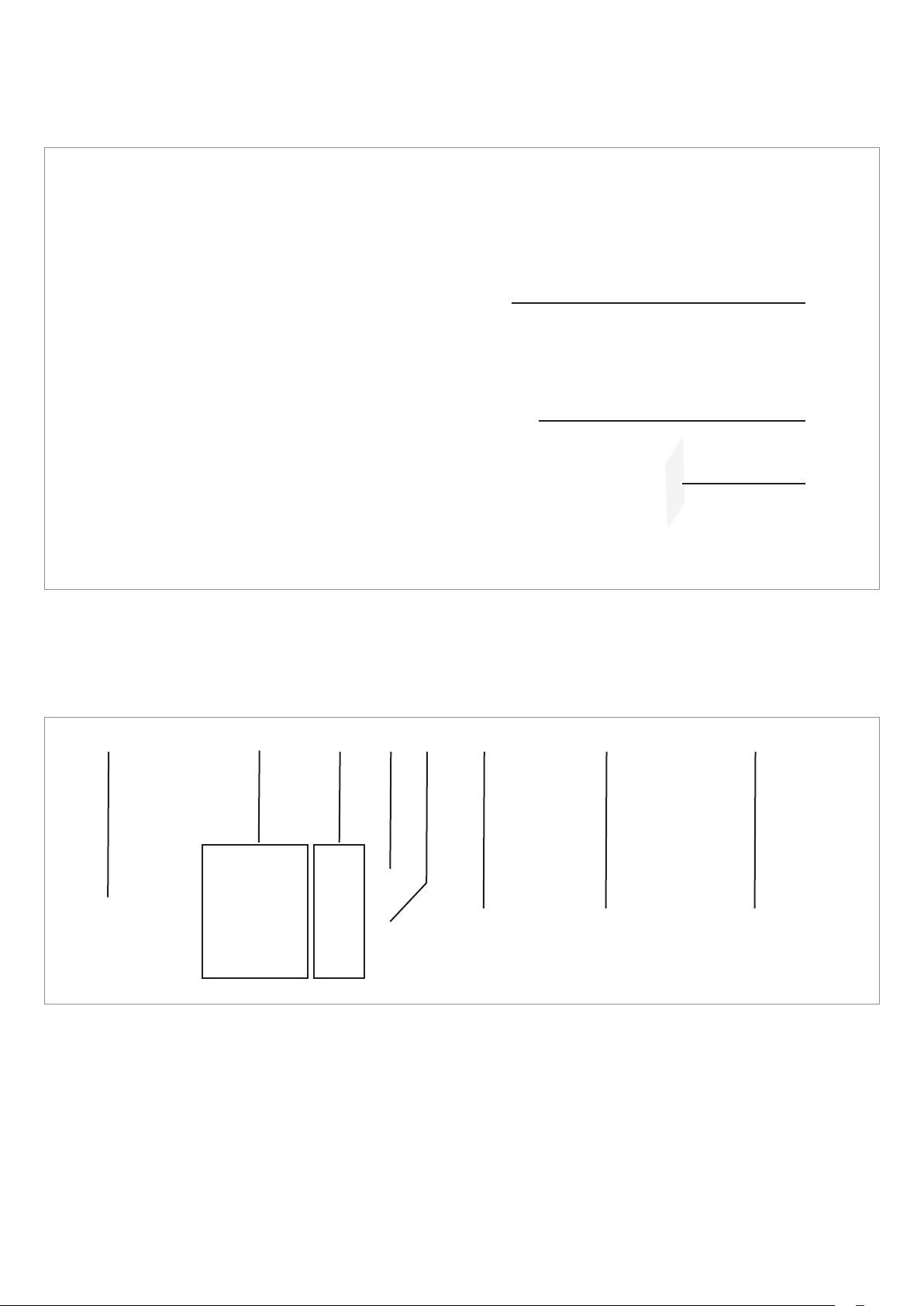
Connecting the power meter
The installation location of the power meter depends on
the features of the specic site. Installation on a DIN rail in
the meter cabinet is preferable.
The power meter can alternatively be installed in a sepa-
rate box inside of which the power meter is protected from
touch and external inuences. A DIN rail is included in the
scope of supply.
The current clamps (1 for P1E, 3 for P3E) must be laid
around the phase cable (L for P1E; L1, L2 and L3 for P3E).
Always comply with applicable regulations when installing
the power meter.
Installation Instructions for the Hybrid E5 Battery Storage System EU V1 EN 2018-09-17
45
Page 46

Connecting the inverter to the mains (AC)
Readying AC cable for use and connecting it
Wiring the AC plug
Depending on how the Hybrid E5 System is used, the AC
plug must be wired differently.
Wiring variants Use
2 = L’ (Load)
3 = N’ (Load)
2 = L’ (Load)
PE
PE
1 The Hybrid E5 System is connected to the mains.
If mains power fails, standalone mode (isolated operation) is used for emergency power supply.
1 = L (Grid)
4 = N (Grid)
2 The Hybrid E5 System is connected to the mains.
Standalone mode (isolated operation) is NOT used
for emergency power supply.
1 = L (Grid)
3 = N’ (Load)
PE
2 = L’ (Load)
3 = N’ (Load)
Wiring variants for the AC plug of the inverter
4 = N (Grid)
1 = L (Grid)
4 = N (Grid)
#
3 The Hybrid E5 System is only used in standalone
mode (isolated operation).
The Hybrid E5 System is NOT connected to the
mains.
This connection variant must be used if no public
mains connection is available at the installation site.
46
Installation Instructions for the Hybrid E5 Battery Storage System EU V1 EN 2018-09-17
Page 47

Connecting the inverter to the mains (AC)
The following images show the wiring for connection variant 1. The wiring must be adjusted
accordingly for the other connection variants.
Readying AC cable for use and connecting it
12 mm
12 mm
52.5 mm
55 mm (PE)
1. Remove the insulation from the cable and wires.
Do not twist the wire ends because this reduces the
contact surface area with the wire end sleeves.
2. Fit and crimp the wire end sleeves to the ends of the
wires.
3. Unscrew the nut and housing from the AC plug.
Installation Instructions for the Hybrid E5 Battery Storage System EU V1 EN 2018-09-17
4. Insert the wires of the AC cable into the correct pin
inserts and tighten with a screwdriver.
The rst image shows the wiring for use of the
Hybrid E5 system in isolated operation; the second
image shows the wiring for use without isolated
operation.
47
Page 48

Connecting inverter to mains (AC)
Readying AC cable of inverter for use and connecting it
5. Place and screw tight the nut and housing.
6. Turn the AC/DC disconnecter on the inverter to the
OFF position.
7. Plug the AC plug into the AC connection on the
inverter and tighten.
48
8. Fasten the AC cable with a strain relief element.
Installation Instructions for the Hybrid E5 Battery Storage System EU V1 EN 2018-09-17
Page 49

Connecting CT cable of the power meter
1. Plug the CT cable into the CT connection on the
power meter.
P1E
P3E
P1E
2. Plug the CT cable into the plug of the measuring
sensors and lay the clamps for the measuring sensors around the phase conductors (L for P1E; L1, L2
and L3 forP3E).
Installation Instructions for the Hybrid E5 Battery Storage System EU V1 EN 2018-09-17
P3E
49
Page 50

Connecting CT cable of the power meter
3. Connect the AC cable to the power meter.
P1E
P3E
50
Installation Instructions for the Hybrid E5 Battery Storage System EU V1 EN 2018-09-17
Page 51

Connecting the inverter to solar modules (DC)
DANGER
NOTICE
Electric shock
Potentially fatal voltages are present at the inverter DC connections. When light falls on the
solar modules, they immediately start to generate electricity. This also happens when light
does not shine directly on the solar modules.
► Never disconnect the inverter from the
solar modules when it is under load.
► Turn the DC isolating switch to the OFF
position.
► Disconnect the connection to the mains so
that the inverter cannot supply energy to
the mains.
► Disconnect the inverter from all AC and DC
voltage sources. Ensure that none of the
connections can be restored accidentally.
► Ensure that the DC cables cannot be
touched accidentally.
Incorrectly dimensioned solar system.
An solar system of the wrong size may cause
damage to the inverter.
► Always pay attention to the technical
specications of the inverter (input voltage
range, maximum current and maximum
input power) when calculating the number
of solar modules.
Safety notice
► Before connecting the solar modules, turn the DC
isolating switch to the OFF position.
Voltage polarity
► Recheck the polarity of the DC voltage of the DC
strings before connecting the solar modules.
NOTICE
Overheating of the DC connections.
Exceeding the maximum current can cause
overheating of the DC connections and result
in a re.
► Always take into account the maximum
current of the DC connections when planning the installation.
Tools
The protective caps lock the DC
plug so that it can only be disconnected from DC connections using the
mounting tool.
► Observe the local regulations with
regards to the protective caps.
Mounting tool for disconnecting the
DC plug and the protective caps from
the DC connections. Available from
Multi-Contact.
Installation Instructions for the Hybrid E5 Battery Storage System EU V1 EN 2018-09-17
51
Page 52

Connecting the inverter to solar modules (DC)
DC cable specications
The DC plugs for all DC connections are supplied with the
inverter.
If you want to order more or need a different size, see the
information in the following table.
b
a
DC connections on the inverter Plugs for DC cables
DC–
^
DC+
1) Included in delivery
Protective devices
► When selecting the necessary protective devices
(e.g. fuses) take into account the Maximum reverse
current of the solar modules.
a b
2
mm
1.5/2.5
4/6
1.5/2.5
4/6
mm
Multi-contact
3-6 32.0010P0001-UR
5.5-9 32.0012P0001-UR
3-6 32.0014P0001-UR
5.5-9 32.0016P0001-UR
3-6 32.0011P0001-UR
5.5-9 32.0013P0001-UR
3-6 32.0015P0001-UR
5.5-9 32.0017P0001-UR
1)
1)
52
+
–
+
–
Installation Instructions for the Hybrid E5 Battery Storage System EU V1 EN 2018-09-17
Page 53

A description of the operating modes is pro-
Nederlands
Select language
Select Country
Selling first
Set Operation Mode
No Yes
Mode: Self consump.
Country: UK 230V
BT 0W Grid 0W
PV 0W Load 0W
Status:Countdown 14s
2018.06.18 09:06
BT 3W Netz 190W
PV 203W Haus 0W
Status: On Grid
2018.06.18 09:08
vided in the user manual.
English
Deutsch
UK 230V
UK 240V
Self consump.
Peak cut
Commissioning
1. Use the and buttons to select the English language and then
press the
2. Use the and buttons to select your country or mains type and then
press the
3. Use the and buttons to select the desired operating mode and then
press the
ENT
ENT
ENT
button.
button.
button.
4. Check that the correct country and desired mode are selected.
If the correct country is selected, use the and buttons to select the
Yes entry and the press the
To change the selection, press the
The inverter starts a self-test lasting approx. 30 seconds.
During the test, the remaining time is displayed and the On LED blinks.
Once the self-test is completed, the standard status for the desired operat-
ing mode is displayed and the On LED is continuously illuminated.
ENT
button.
EXIT
button.
Installation Instructions for the Hybrid E5 Battery Storage System EU V1 EN 2018-09-17
53
Page 54

Technical specications
Inverter
Input (DC) Hybrid E5 Inverter
Recommended maximum PV power 7 kW
Maximum input power (total / per input) 5.5 kW / 2.75 kW
Rated input power 5.3 kW
Maximum input voltage 600 V
Operating input voltage range 100 ... 550 V
Nominal voltage 370 V
Cut-in voltage 125 V
Cut-in power 30 W
MPP input voltage range 100 ... 550 V
MPP input voltage range with full power 220 ... 450 V
Maximum total input current (DC1 / DC2) 24 A (12 A / 12 A)
Maximum breaking current 15 A per DC input
Number of MPP trackers
Parallel inputs: 1 MPP tracker; separate inputs: 2 MPP
Number of DC inputs, total (DC1/DC2) 2 (1 / 1)
Electrical isolation No
Overvoltage category
1)
P
DC
DC
DC
DC
DC
DC
trackers
II
Output (AC) Hybrid E5 Inverter
Maximum apparent power with solar system only
2)
5.25 kVA
Rated apparent power with solar system only 5.0 kVA
Rated active power with solar system only
3)
Maximum active power with solar system and battery
3)
5.0 kW at 21.7 A
6.4 kW at 28 A
Maximum active power with battery alone 3.6 kW at 15.6 A
Nominal voltage
4)
230 VAC ± 20%, 1 Phase + N + PE
Switch-on current 16 A / 100 µs
Nominal frequency 50 / 60 Hz
Frequency range
4)
45 ... 65 Hz
Congurable power factor 0.8 cap ... 0.8 ind
Total harmonic distortion <3% at rated apparent power
DC injection <0.5% at nominal current
Power loss during night operation with/without battery <30 W / <10 W
Surge protection
5)
Overvoltage category
1)
28 A
III
Mechanical details Hybrid E5 Inverter
Dimensions (W x H x D) 510 × 445 × 177 mm
Weight 27 kg
Cooling Natural convection
AC connection type Amphenol C016 20E004 801 2
DC input connection type Multi-Contact MC4
Battery cable connection type Phoenix Contact PV-CF-S 6-16 and PV-CM-S 6-16
Communication interfaces
2x RS485, 1x dry contacts, 1x external power-off, 6x digital
inputs
54
Installation Instructions for the Hybrid E5 Battery Storage System EU V1 EN 2018-09-17
Page 55

Technical specications
Inverter
General specications Hybrid E5 Inverter
Delta model name Hybrid E5
Delta part number RPI502E121000
Peak efciency 97.2%
European efciency 96.5%
Operating temperature range -25 ... +60 °C
Operating temperature range without derating -25 ... +40 °C
Relative humidity 0 ... 100%, non-condensing
Max. operating height 2000 m above sea level
Noise level (at a distance of 1 m) <40 dB(A)
Standards and guidelines Hybrid E5 Inverter
Protection degree IP65 (Electronics)
Safety class I
Amount of internal/external contamination II / III
Overload behavior Current limit, power limit
Safety IEC 62109-1 / -2, IEC 62040, CE conformity
EMC EN 61000-6-2, EN 61000-6-3
Fault-free operation IEC 61000-4-2 / -3 / -4 / -5 / -6 / -8
Harmonic distortion EN 61000-3-2
Fluctuations and brillations EN 61000-3-3
Mains connection guidelines You will nd the current list at www.solar-inverter.com.
1)
IEC 60664-1, IEC 62109-1
2)
For cos phi = 1 (VA = W)
3)
The maximum input power of the inverter into the mains is programmed according to the respective country regulations. In Germany,
input power is limited to 4.6 kW.
4)
AC voltage and frequency ranges are programmed according to the respectively applicable national regulations.
5)
If the specied current is exceeded, the inverter automatically switches off. If this happens, reduce the connected loads.
Installation Instructions for the Hybrid E5 Battery Storage System EU V1 EN 2018-09-17
55
Page 56

Technical specications
Battery box
BX 6.0 battery box
Delta model name Hybrid BX 6.0
Delta part number RPB602201120
Rated capacity 6 kWh
Maximum capacity 6.4 kWh
Usable capacity (80% discharge) 4.8 kWh
Maximum number of charging cycles (80% discharge) 6000
Voltage range 85 ... 104 V
Nominal charging power 2.5 kW
Nominal discharge power 3 kW
Maximum charging current 30 A
Maximum discharge current 35 A
Battery technology Lithium ions
Dimensions 553 x 596 x 200 mm
Weight 75 kg
Protection degree IP55
Optimal operating temperature range +10 ... +30 °C
Maximum temperature range:
● Charging 0 ... +45 °C
● Discharging -10 ... +45 °C
Relative humidity 0 ... 90%, non-condensing
Certicates UN38.3
DC
56
Installation Instructions for the Hybrid E5 Battery Storage System EU V1 EN 2018-09-17
Page 57

Technical specications
Power meter, Smart Monitor
P1E power meter P3E power meter
Delta model name P1E P3E
Communication WLAN (N1) / RS485
Status display LED
Nominal operating voltage (L – N) 100 V
Operating voltage range (L – N) 85 VAC ... 264 V
... 240 V
AC
AC
AC
Maximum operating current 120 A
Frequency range 45 ... 65 Hz
Maximum power consumption without/with WiFi 2 W / 4 W 3 W / 6 W
Operating temperature range -20 ... +50 °C
Storage temperature range -20 ... +60 °C
Relative humidity 30 ... 85%, non-condensing
Dimensions 93 x 47.3 x 66.5 mm 93 x 70 x 66.5 mm
Weight 145 g 200 g
Protection degree IP20
Safety standard IEC 60950-1
Emissions EN 55022, Class B
230 V
AC
130 VAC ... 260 V
AC
Smart Monitor
Delta model name R4E
Nominal operating voltage
1)
Operating voltage range 10 ... 16 V
12 V
DC
DC
Power consumption <6 W (without USB connection)
Display
7 inch TFT-LCD touchscreen
800 x 480 pixels, 24 Bit RGB
Communication RS485 / WiFi
Operation
Operating temperature range -20 ... +50 °C
Storage temperature range -20 ... +60 °C
Relative humidity 30 ... 85%, non-condensing
Dimensions 120 x 190 x 32 mm
Weight 440 g
Protection degree IP20
Safety standard
Installation Instructions for the Hybrid E5 Battery Storage System EU V1 EN 2018-09-17
57
Page 58

Space for notes
58
Installation Instructions for the Hybrid E5 Battery Storage System EU V1 EN 2018-09-17
Page 59

Space for notes
Installation Instructions for the Hybrid E5 Battery Storage System EU V1 EN 2018-09-17
59
Page 60

Customer Service - Europe
Austria service.oesterreich@solar-inverter.com 0800 291 512 (toll free)
Belgium support.belgium@solar-inverter.com 0800 711 35 (toll free)
Bulgaria support.bulgaria@solar-inverter.com +421 42 4661 333
Czech Republic podpora.czechia@solar-inverter.com 800 143 047 (toll free)
Denmark support.danmark@solar-inverter.com 8025 0986 (toll free)
France support.france@solar-inverter.com 0800 919 816 (toll free)
Germany service.deutschland@solar-inverter.com 0800 800 9323 (toll free)
Greece support.greece@solar-inverter.com +49 7641 455 549
Great Britain support.uk@solar-inverter.com 0800 051 4281 (toll free)
Israel supporto.israel@solar-inverter.com 800 787 920 (toll free)
Italy supporto.italia@solar-inverter.com 800 787 920 (toll free)
Netherlands ondersteuning.nederland@solar-inverter.com 0800 022 1104 (toll free)
Poland serwis.polska@solar-inverter.com +48 22 335 26 00
Portugal suporte.portugal@solar-inverter.com +49 7641 455 549
Slovakia podpora.slovensko@solar-inverter.com 0800 005 193 (toll free)
Slovenia podpora.slovenija@solar-inverter.com +421 42 4661 333
Spain soporto.espana@solar-inverter.com 900 958 300 (toll free)
Switzerland support.switzerland@solar-inverter.com 0800 838 173 (toll free)
Turkey support.turkey@solar-inverter.com +421 42 4661 333
Other European countries support.europe@solar-inverter.com +49 7641 455 549
© Copyright – Delta Electronics (Netherlands) B.V. – All rights reserved.
All information and specications can be modied without prior notice.
Installation Instructions for the Hybrid E5 Battery Storage System EU V1 EN 2018-09-17
 Loading...