

Page 1

Triplex Real Time Stand Alone DVR
1
User's Manual
Triplex Real Time Stand Alone DVR
[ 4 / 8 / 16 Channel DVR ]
Page 2
Triplex Real Time Stand Alone DVR
2
CAUTION
TO REDUCE THE RISK OF ELECTRICAL SHOCK, DO NOT OP EN C OVERS.
TO REDUCE THE RISK OF ELECTRICAL SHOCK, DO NOT OP EN C OVERS.
NO USER SERVICEABLE PARTS INSIDE. REFER SE RVICING TO QUALIFIED S
NO USER SERVICEABLE PARTS INSIDE. REFER SE RVICING TO QUALIFIED S
ERVICE PERSONNEL.
ERVICE PERSONNEL.
Note
Note
PLEASE READ THIS MANUAL THOROUGHLY FOR EFFECTIVE AND SAFE USAGE
PLEASE READ THIS MANUAL THOROUGHLY FOR EFFECTIVE AND SAFE USAGE
OF THE DEVICE.
OF THE DEVICE.
This equipment had been tested and found to comply with the limits for a CLASS A
digital device, pursuant to Part 15 of FCC Rules. These limits are designed to provide
reasonable protection against harmful interference when the equipment is operated in
a commercial environment.
Please beware of the following precautions before installing the DVR.
• Avoid any place with moisture, dust, or soot.
• Avoid any place with direct sunlight or heating appliances.
• Keep the product away from electric shock or ma gneti c sub stan ce s .
• Avoid high or low temperature.
(Recommended operation temperature is between 0°C ~ 40°C).
• Do not place any conductive material through the ventilation.
• Turn off the system before installation.
• Ensure enough space for cable connections.
• Place the system on a solid surface with sufficient air ventilation.
Avoid any surface that vibrates.
• Placing the system near electronic devices such as radio or TV may cause breakdown
to the product.
• Do not disassemble the product without an assistance from the manufacturer.
• Do not place any heavy object on the system.
Page 3
Triplex Real Time Stand Alone DVR
3
CHAPTER 1. KEY FEATURES
CHAPTER 2. PACKING DRTAILS
CHAPTER 3. NAMES AND FUNCTIONS
3.1 FRONT PANEL
3.2 REAR PANEL
CHAPETR 4. INSTALLATION
4.1 TOTAL CONNECTION DIAGRAM
4.2 INDIVIDUAL CONNECTION
4.2.1 POWER
4.2.2 CAMERA
4.2.3 MONITOR
4.2.4 VGA
4.2.5 AUDIO
4.2.6 USB
CHAPTER 5. OPERATION
5.1 FACTORY DEFAULT
5.2 FRONT PANEL CONTROL
FUNCTION
5.2.1 MULTI DISPLAY
5.2.2 PIP DISPLAY
5.2.3 AUTO SEQUENCE DISPLAY
5.2.4 TRIPLEX DISPLAY
5.2.5 DVR INFORMATION
5.2.6 RECORD
5.2.7 SEARCH & PLAYBACK
5.3 REMOTE CONTROLLER
5.3.1 REMOTE CONTROL
FUNCTION
5.3.2 MUTE
Contents
6~7
8
9~10
13
14
15
15
16
17
18
18
19
19
20
9
21
22~23
24
25
26~27
28
11~12
28
13
14
14
29
Page 4
Triplex Real Time Stand Alone DVR
4
5.3.3 DIGITAL ZOOM
5.3.4 PANORAMA
5.3.5 PTZ CONTROL
5.3.6 BACKUP
5.3.6.1 CD-RW BACKUP
5.3.6.2 USB BACKUP
CHAPTER 6. SETUP MENU
6.1 LANGUAGE
6.2 SYSTEM SETUP
6.2.1 HDD SETUP
6.2.2 PASSWORD SETUP
6.2.3 CHANNEL NAME SETUP
6.2.4 DATE/TIME SETUP
6.2.5 BEEP & PTZ SETUP
6.2.6 SYSTEM RESET
6.3 DISPLAY SETUP
6.3.1 BLANK CHANNEL SETUP
6.3.2 PIP CHANNEL SETUP
6.3.3 ADJUST CHANNEL SETUP
6.3.4 VIDEO SIGNAL TYPE
6.3.5 SEQUENCE
6.3.6 BOUNDARY COLOR
6.3.7 BLANK COLOR
6.4 EVENT SETUP
6.4.1 RECORD TIME
6.4.2 SENSOR IN
6.4.3 EVENT ACTION
6.4.4 MOTION SETUP
6.5 RECORD SETUP
6.5.1 RECORD TYPE
6.5.2 RECORD SPEED
6.5.3 RECORD QUALITY
6.5.4 PB SPEED
6.5.5 CHANNEL ENABLE
6.5.6 AUDIO SETUP
Contents
31
32~33
34~40
41
42
44
47
48
48
49
52
50
51
51
53
52
53
41
53
54
55
56
56
56
42
30
46
56
43
45
56
57
57
34~35
36~40
Page 5
Triplex Real Time Stand Alone DVR
5
Contents
59
64
65
58
61~62
66
67
59~60
63
66
68
68
68
68
69~70
71~72
6.5.7 SCHEDULE SETUP
6.6 NETWORK SETUP
CHAPTER 7. EXTERNAL TERMINAL
INFORMATION
7.1 RS-232
7.2 ALARM IN/OUT & RS-485
7.3 VGA (Optional)
7.4 ETHERNET & USB
CHAPTER 8. SPECIFICATIONS
CHAPTER 9. HDD & CD-RW
INSTALLATION
9.1 HDD INSTALLATION
9.2 CD-RW INSTALLATION
CHAPTER 10. CLIENT NETWORK
VIEWER MANUAL
10.1 SYSTEM REQUIREMENT
10.2 NETWORK ENVIRONMENT
10.3 NETWORK VIEWER
INSTALLATION
10.4 NAMES & FUNCTIONS
10.5 OPERATION
10.5.1 LIVE VIEW MODE
10.5.2 PLAY BACK MODE
10.5.3 DRIVE SCAN MODE
10.5.4 FILE PLAY MODE
10.5.5 CD PLAY MODE
CHAPTER 11. Q & A
71
73
76
74
75
77~78
57
Page 6
Triplex Real Time Stand Alone DVR
6
CHAPTER 1. KEY FEATURES
Operation
• Display, Playback, Recording, Network transmission simultaneously
• Real time single or multi-screen di splay
• Triplex display (8ch Live & 8ch playback display)
• Pan & Tilt, 2X digital zoom and 3 PIP display
• Easy operation by IR remote controller
• Hidden camera option (covert)
• User-friendly setup menu and oper ation
Playback
• Multi-screen playback (Full, Quad, 6/ 8/ 9/ 13/ 16 split)
• Search by date / time list, event list and data / time
• Playback speed mode to be adjustable
Recording
• Recording quality level to be adjustable
• Camera frame rate can be set by user
• The recording speed of max. 120 images per second (NTSC)
• Manual, schedule and event (motion, alarm) re cor ding
• Recording image size (EACH / CIF) to be adjustable
• 1 channel audio recording
Network
• Live and playback viewing and recording with exclusive client viewer
• Remote control via networked PC with the exclusive client viewer
• (The viewer software provided in the package.)
• Flexible connections - 10/ 100 Mbps Ethernet / ADSL
Page 7

Triplex Real Time Stand Alone DVR
7
Audio
• 1 channel audio recording in real time
• One audio channel setup for each channel
BACKUP
• Remote backup on network PC with the exclusive client viewer
• CD-RW backup
• USB 2.0 backup (Video file & Still image backup)
General
• PAL / NTSC in a display setup menu to be adjustable
• Built-in hardware Watchdog
• S-Video output
• Alarm In/Out, RS-485, RS-232 Connections
• Loop-through connections
• Multiple Languages
• VGA output for PC monitor (Optional)
Page 8
Triplex Real Time Stand Alone DVR
8
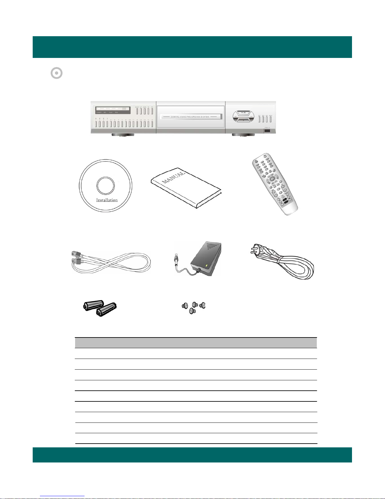
CHAPTER 2. PACKING DETAILS
4. Remote controller
3. User’s Manual
1. DVR unit
2. Network Viewer Program CD
5. LAN Cable 7. Power Cord
6. DC Adaptor
9. HDD Screws
8. Battery
CONTENTS
1. DVR unit
2. Network Viewer Program CD
3. User’s Manual
4. Remote controller
5. LAN Cable
6. DC Adaptor
7. Power Cord
8. Battery
9. HDD Screws
Page 9
Triplex Real Time Stand Alone DVR
9
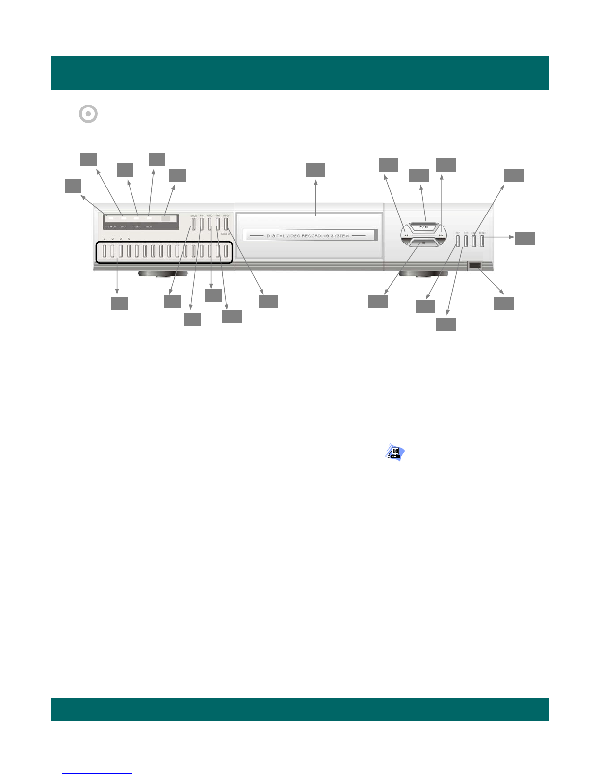
3.1 FRONT PANEL
1. 1 to 16 Channel Sele ction / Direction
• To select a channel to be viewed as full-size screen during live display or playback.
• To navigate in the menu, press Up(CH1) / Down(CH2) / Left(CH3) / Right(CH4).
2 ~ 5. LED Signs
• There are four LED signs that indicate current status.
2. POWER : DVR power status
3. NET : ON means that LAN cable is connected and it is ready to transfer information via network.
If user accesses to the DVR via network, network icon ( ) is showed
in the upper right side of screen.
If someone accesses to the DVR via network, LED light turns on.
4. PLAY : ON means the DVR is in search mode of playback.
5. REC : ON means the DVR is on recording.
6. Remote Controller Sensor
7. MULTI
• It converts to live display mode directly.
• To surf various live display modes like 16CH, 13CH, 9CH, 8CH and 6CH display
by pressing the button repeatedly.
8. PIP
• To convert to PIP mode (Picture in Picture ).
• To surf various PIP modes like 1PIP, 2PIPs and 3PIPs by pressing the button repeatedly.
9. AUTO
• To convert to auto sequence mode.
• If you press AUTO on the front panel, channels will be automatically switched as follows.
- Ch1 -> Ch2 -> Ch3 ->….-> Ch14 -> Ch15 -> Ch16 -> 16Ch in CIF -> Ch1 -> Ch2 …
keeping this order until you press Auto button again to release the function.
CHAPTER 3. NAMES AND FUNCTIONS
1
2
3
4
5
6
9
7
8
10
11
17
20
19
18
13
14
15
16
12
21
Page 10

Triplex Real Time Stand Alone DVR
10
10. TRI (TRIPLEX)
• To convert to triplex function like 8 channel live display and 8 channel playback in the screen
simultaneously.
• Press the button first, you will have CH1 ~ CH 8 live displays and playbacks and press it again,
you will do next other channels like CH9 ~ CH16 live displays and playbacks.
- When you press the button in live display mode with no playback,
you will see 8 channel live displays and 8 channel playbacks with no video.
- When you press the button in playback mode,
you will see 8 channel live displays and 8 channel playbacks that you have selected.
11. INFO (INFORMATION) / BACKUP
• To show system information of DVR, press it in live display mode.
• To backup videos, press it and select CD-RW or USB in playback mode.
12. CD-Burner
• To burn CD for data back-up
13. REWIND (◀◀)
• Select speed level among 4 levels
14. PLAY (▶) / PAUSE (II)
• To play and pause the recorded videos
15. Faster Forward (▶▶)
• Select speed level among 6 levels
16. STOP (■)
• To stop playing videos
17. RECORD
• To start and stop recording.
18. SEARCH
• To access recordings from HDD
19. ENTER
• To enter a selection
20. MENU
• To access System Setup Menu.
21. USB 2.0 port
• To backup video & still image
Page 11
Triplex Real Time Stand Alone DVR
11
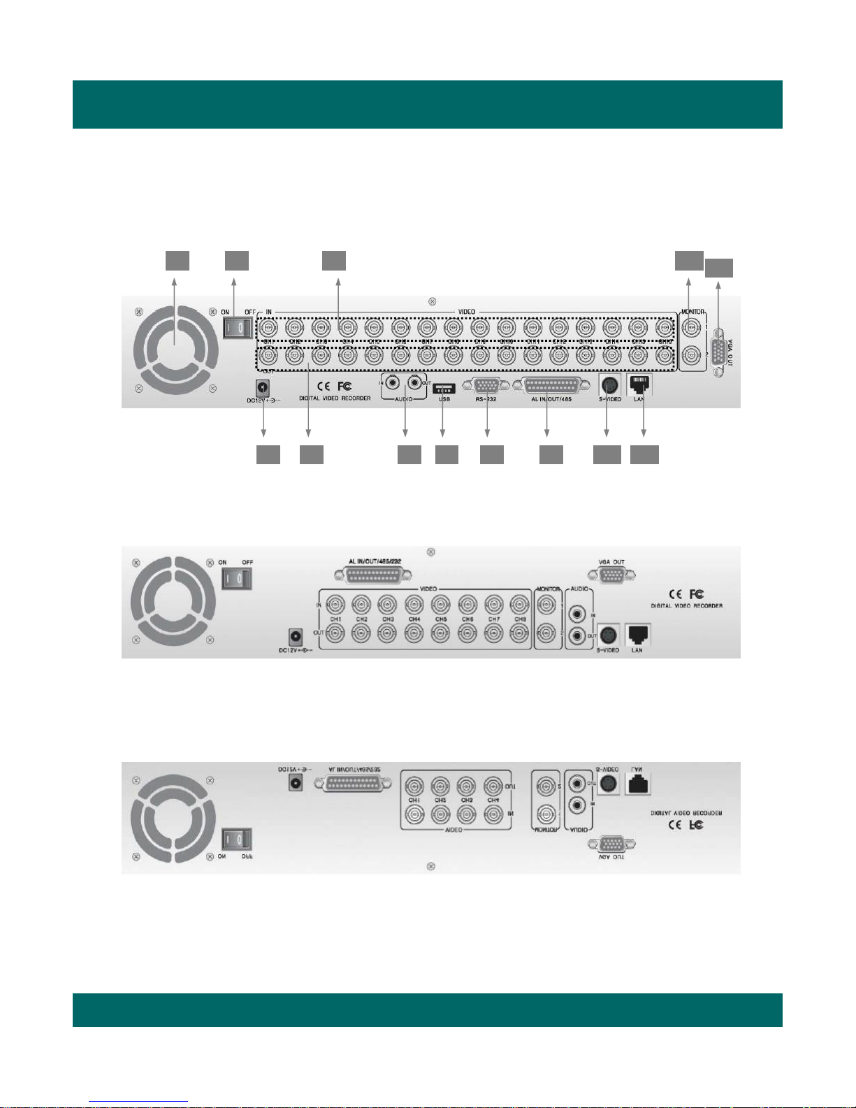
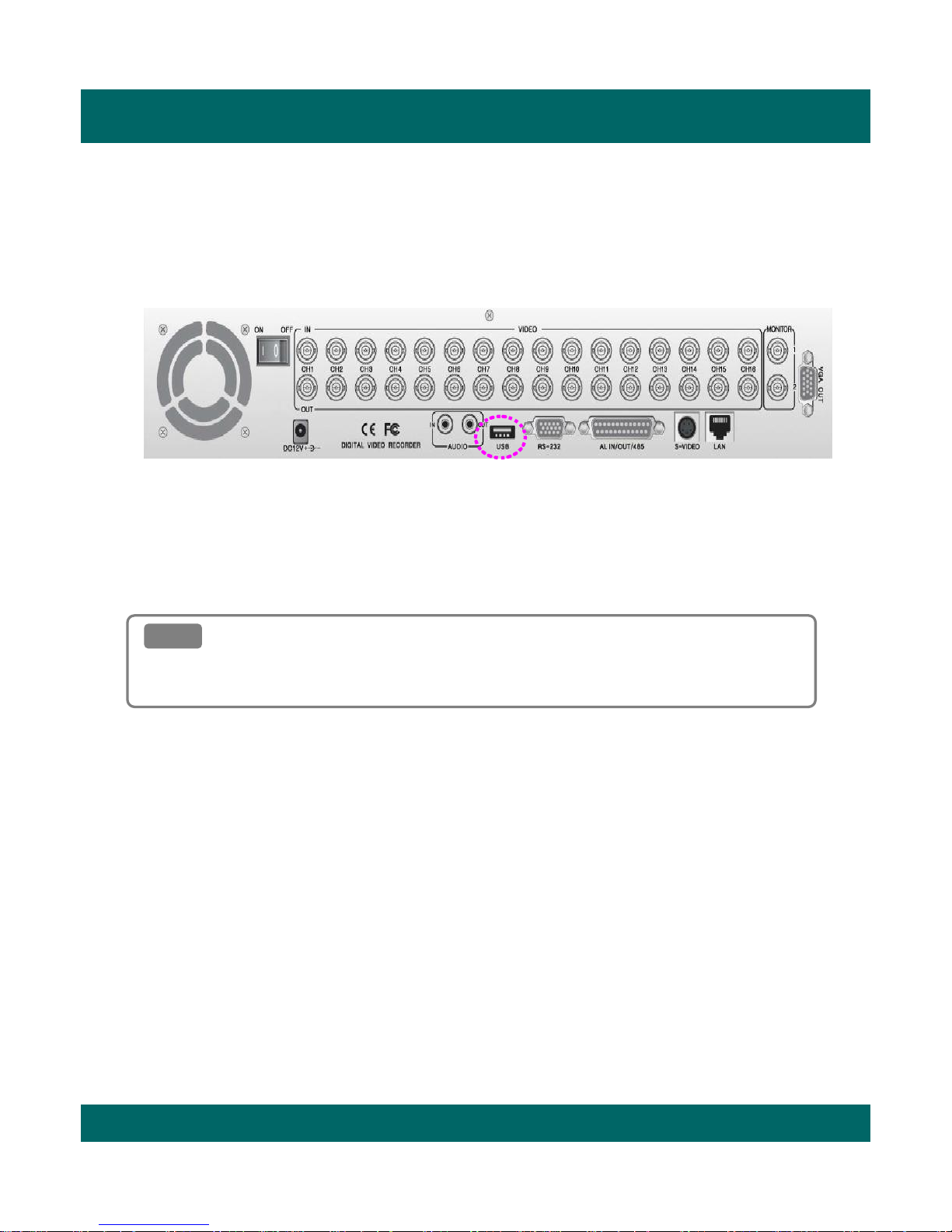
3.2 REAR PANEL
1 2 4 12
13
[ 16CH DVR ]
763 5 9 108 11
[ 8CH DVR ]
[ 4CH DVR ]
Page 12

Triplex Real Time Stand Alone DVR
12
1. Cooling Fan
2. Power Switch
3. DC Power Inlet
4. 16 BNC connectors for camera input
5. 16 BNC connectors for auto loop-through
These are mainly to retransmit just receiving video signals directly from external cameras to other
external devices.
6. Audio In / Out Port
7. USB 2.0 Port
8. RS-232 Port (9 Pin D-Sub Connector)
9. Alarm In / Out and RS-485 Port (25 Pin D-Sub Connector)
• It is to communicate with external sensors, alarm and PTZ camera to control.
10. S-Video Output
11. LAN Terminal
• It is to connect to LAN or Internet.
12. BNC connectors for monitor output
• These are mainly for monitors. And also you can use these for VCR recorder backup.
13. VGA Output Port (Optional)
• This is mainly for PC monitors.
Page 13
Triplex Real Time Stand Alone DVR
13
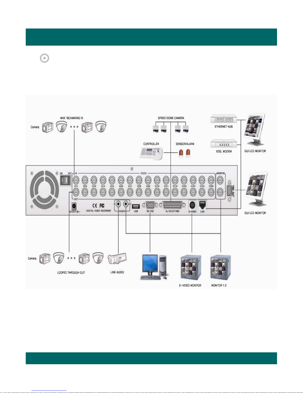
CHAPTER 4. INSTALLATION
4.1 TOTAL CONNECTION DIAGRAM
Page 14
Triplex Real Time Stand Alone DVR
14
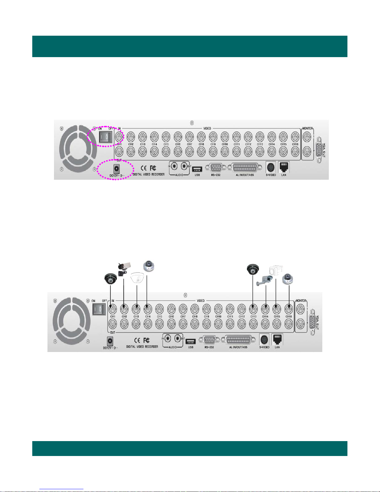
4.2 INDIVIDUAL CONNECTION
4.2.1 POWER
4.2.2 CAMERA
16 Cameras
…………………………...............
* Connect the DC adaptor provided in the package.
* And then turn on the power switch.
* Connect a female BNC connector of each camera to a male BNC connector, ”CAMERA IN” port.
Page 15
Triplex Real Time Stand Alone DVR
15
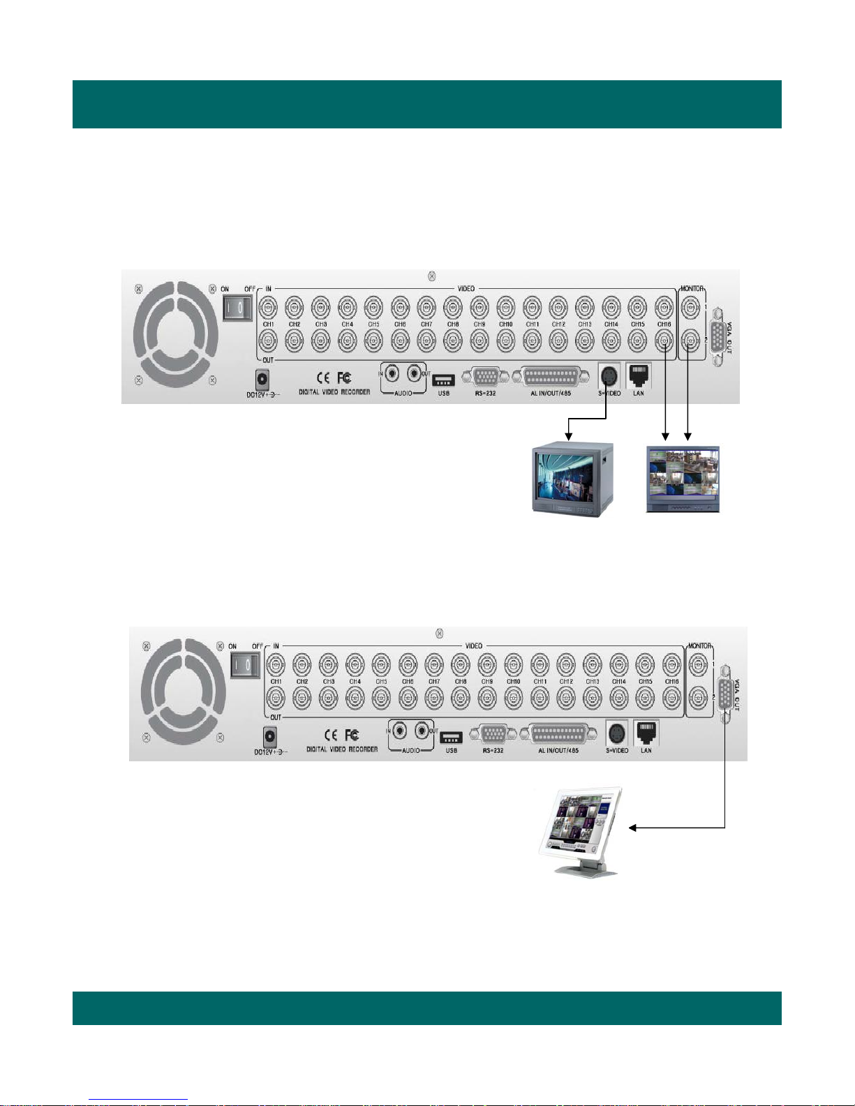
4.2.3 MONITOR
4.2.4 VGA (Optional)
* Connect the female BNC for monitor output.
* Connect the male DIN socket for S-VIDEO monitor output.
[ S-VIDEO ] [ Main Monitor ]
* Connect the D-sub connector of computer (VGA) monitor to VGA out of DVR.
[ PC monitor ]
Page 16
Triplex Real Time Stand Alone DVR
16
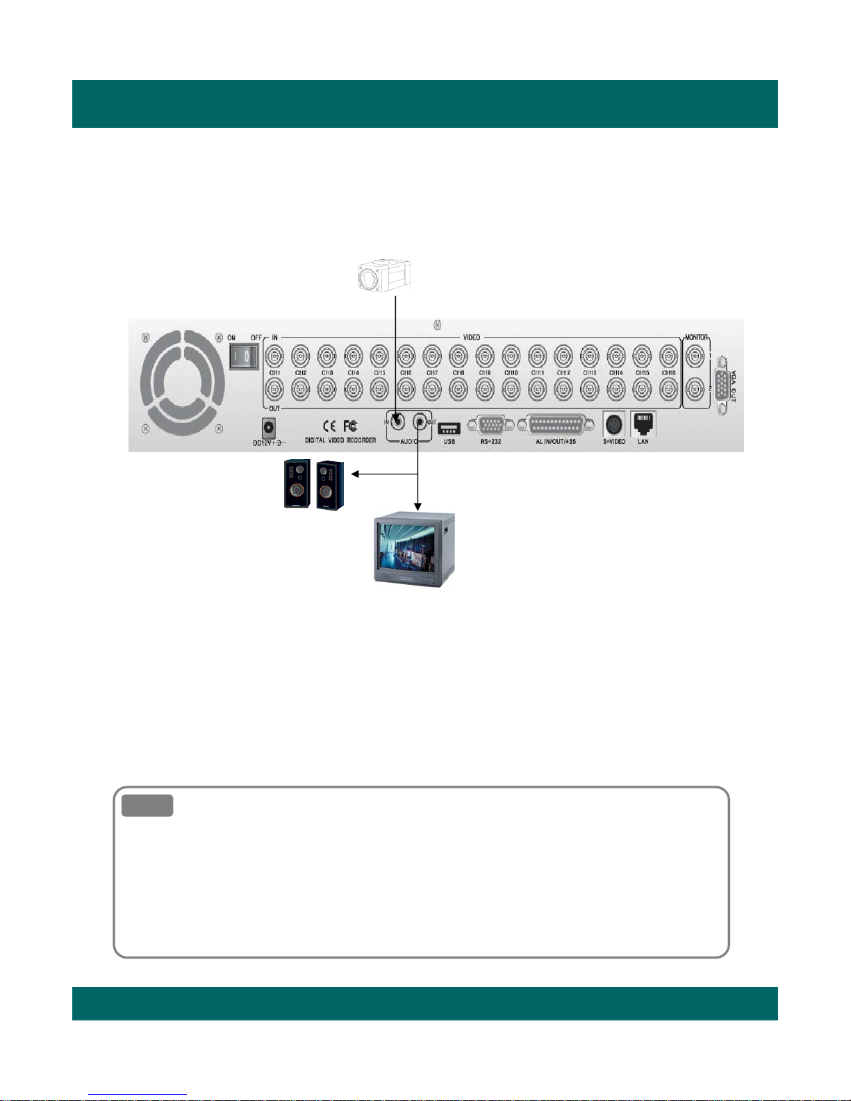
4.2.5 AUDIO
Line Audio
Monitor
Amplified
Speaker
* Audio Input
- AUDIO IN : Connect the RCA Line Jack of the relevant equipment (for example, a camera with a built-
in microphone ) to the AUDIO IN port.
* Audio Output
- AUDIO OUT : Connect the RCA Line output to a monitor with a built-in speaker.
Note
Note
This DVR can be connected only with a line audio and not support a microphone for audio input
and output.
To record audio, AUDIO function should be enable in the AUDIO setup of main menu.
As the audio is linked to a camera, it is required that linked camera should be viewed in the screen
during playback in order to hear the recorded audio.
Page 17
Triplex Real Time Stand Alone DVR
17
4.2.6 USB (USB 2.0 port)
* The USB port is provided to connect USB memory stick for video backup & still image copying.
Note
Note
For further details, please go to USB backup, page 36.
How to operate USB backup
Page 18
Triplex Real Time Stand Alone DVR
18
CHAPTER 5. OPERATION
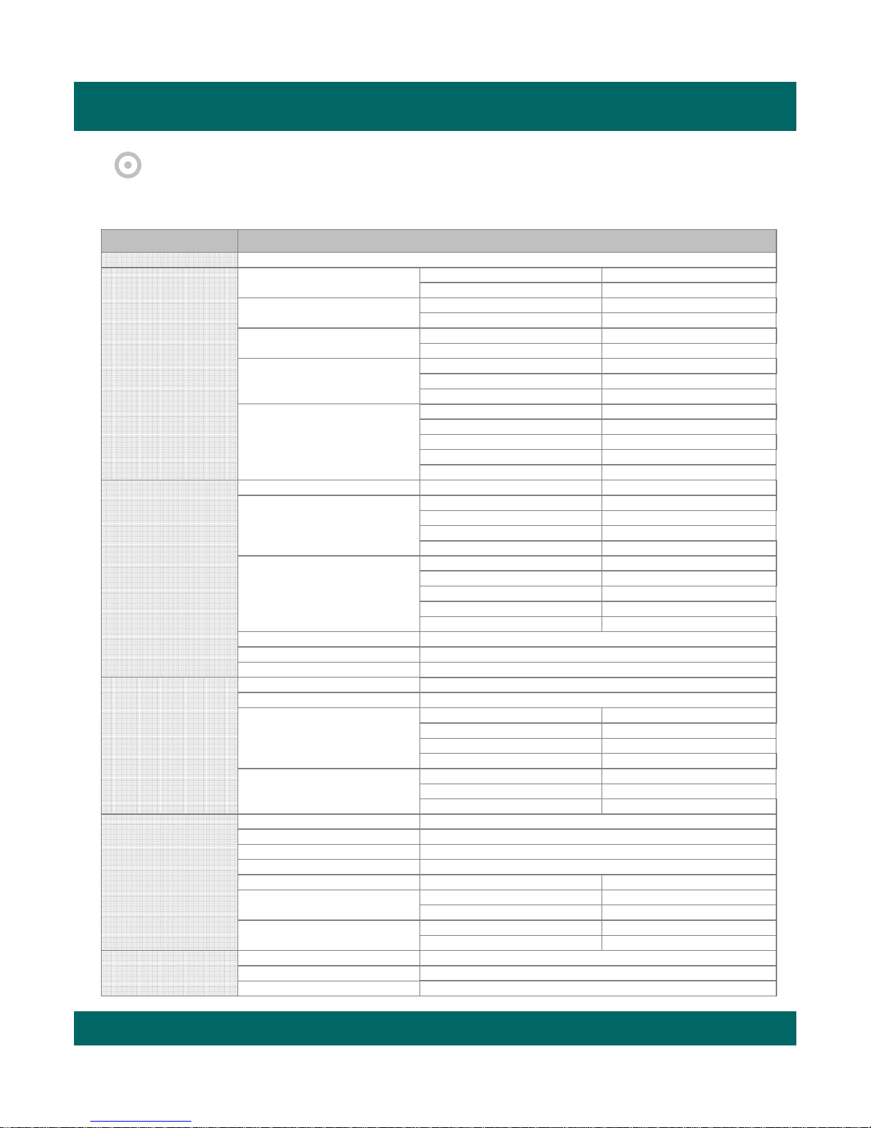
5.1 FACTORY DEFAULT
Main Menu
English
Language
Sub Menu
HDD Setup
ON
Password Setup
Channel Name Setup
Date / Time Setup
Beep & PTZ Setup
System Setup
Display Setup
Event Setup
Record Setup
Network Setup
Overwrite
ON
Record OSD
OFF
Select
1111
Input
ON
Live
ON
PB
ON
Live
ON
PB
YY/ MM/ DD
Type
PELCO-D
PAN / TILT
3
PTZ Speed
9600 BPS
Baud Rate
ON
Record Beep
ON
HDD Fail
Blank Channel Setup
PIP Channel Setup
Adjust Channel Setup
Sequence
Boundary
Blank
CH1 ~ CH16
OFF
CH 1
Main
CH 2
Sub 1
CH 3
Sub 2
Sub 3
CH 4
Channel
CH 1
50
CON
50
HUE
50
BRI
COL
50
1 sec
White
Blue
Rec. Time
Sensor In
Event Action
Motion Setup
30 sec
N.O
ON
Alarm Out
BEEP + OSD
Sensor
OSD
Video Loss
Motion
OFF
CH 1
Channel
9
Sensitivity
Area
Full
Quality
PB Speed
Audio Setup
Schedule Setup
Type
Rec. Speed
Channel Enables
EACH
60 F/S
Level 3
AUTO
CH1 ~ CH16
ON
Channel
CH 1
Display
ON
Schedule
OFF
Day
Daily
Network ID
Password
Bypass
OFF
12345678
00000000
Page 19
Triplex Real Time Stand Alone DVR
19
5.2 FRONT PANEL CONTROL FUNCTION
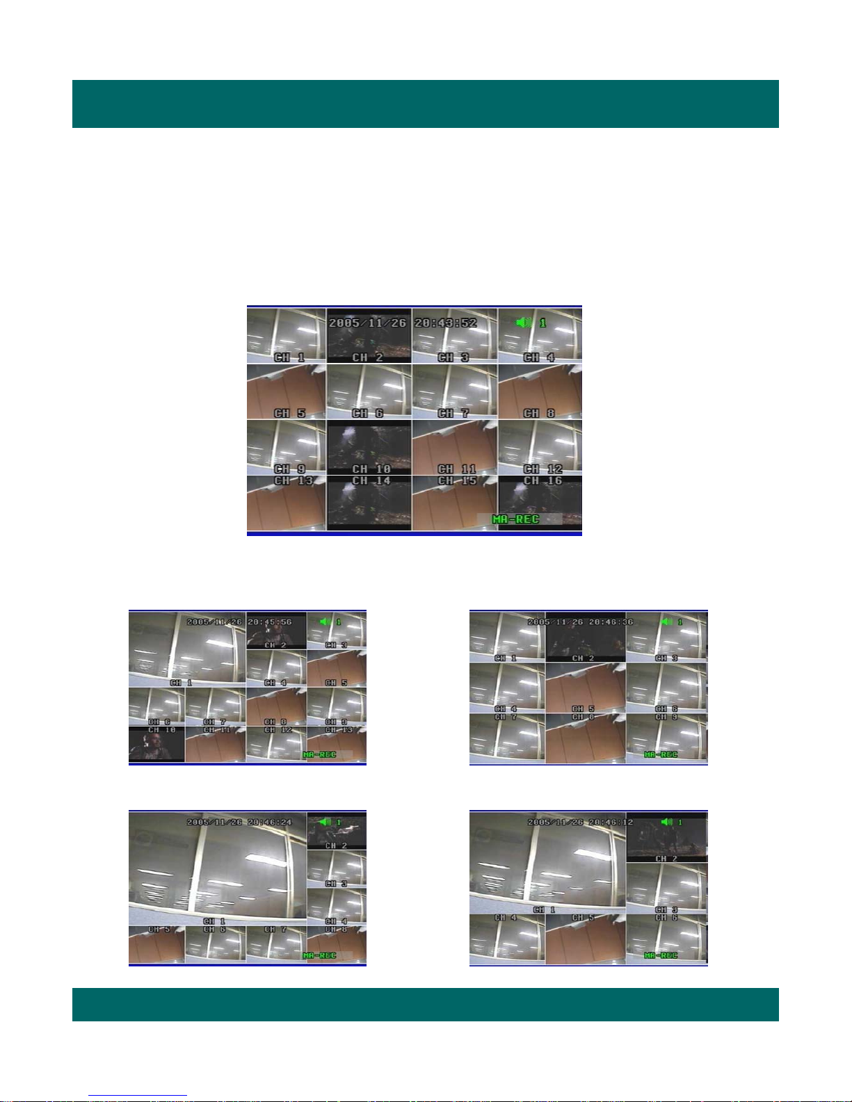
5.2.1 MULTI DISPLAY
Users can enjoy this “MULTI DISPLAY” functions in any mode.
It converts to 16 channel live display on the screen as below by pressing MULTI button.
* To convert to live display, press MULTI button in any mode.
You can surf 13 CH / 9 CH / 8 CH / 6 CH display by pressing MULTI button repeatedly.
[ 13 CH display Mode] [ 9 CH display Mode]
[ 6 CH display Mode]
[ 8 CH display Mode]
Page 20
Triplex Real Time Stand Alone DVR
20
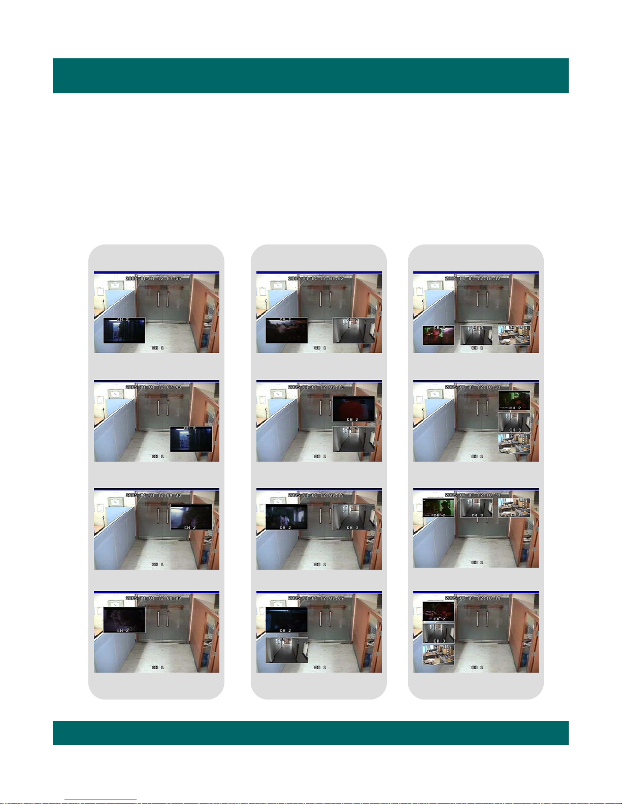
You can select PIP ( Picture In Picture ) options by pressing PIP button repeatedly. PIP mode offers a
convenient way of monitoring multiple channels while focusing more attention on a particular channel. It
has a main video channel view and up to 3 small video channel views on the screen.
You can surf 1 PIP/ 2 PIPs/ 3 PIPs mode with 4 positions by pressing PIP button repeatedly.
To release this mode, press MULTI button on the front panel.
[ 1PIP ] [ 2 PIPs ] [ 3 PIPs ]
5.2.2 PIP DISPLAY
Page 21

Triplex Real Time Stand Alone DVR
21
5.2.3 AUTO SEQUENCE DISPLAY
If you select Auto Sequence mode, channels will be switched automatically among 17 types of display in the
order of “CH 1-CH 2-CH3- …- CH 15- CH 16-16 channel mode” and keep the order until you press MULTI
button. The DVR skips channels with no video.
You can find that the DVR indicates “AUTO” in the upper left of the screen in this mode.
To release this mode, press AUTO button again.
[ CH 1 ] [ CH 3 ][ CH 2 ]
[ CH 15][ CH 16 ][ 16 CH CIF Mode ]
[…….]
It indicates current status is in “Auto Sequence mode”.
Page 22
Triplex Real Time Stand Alone DVR
22
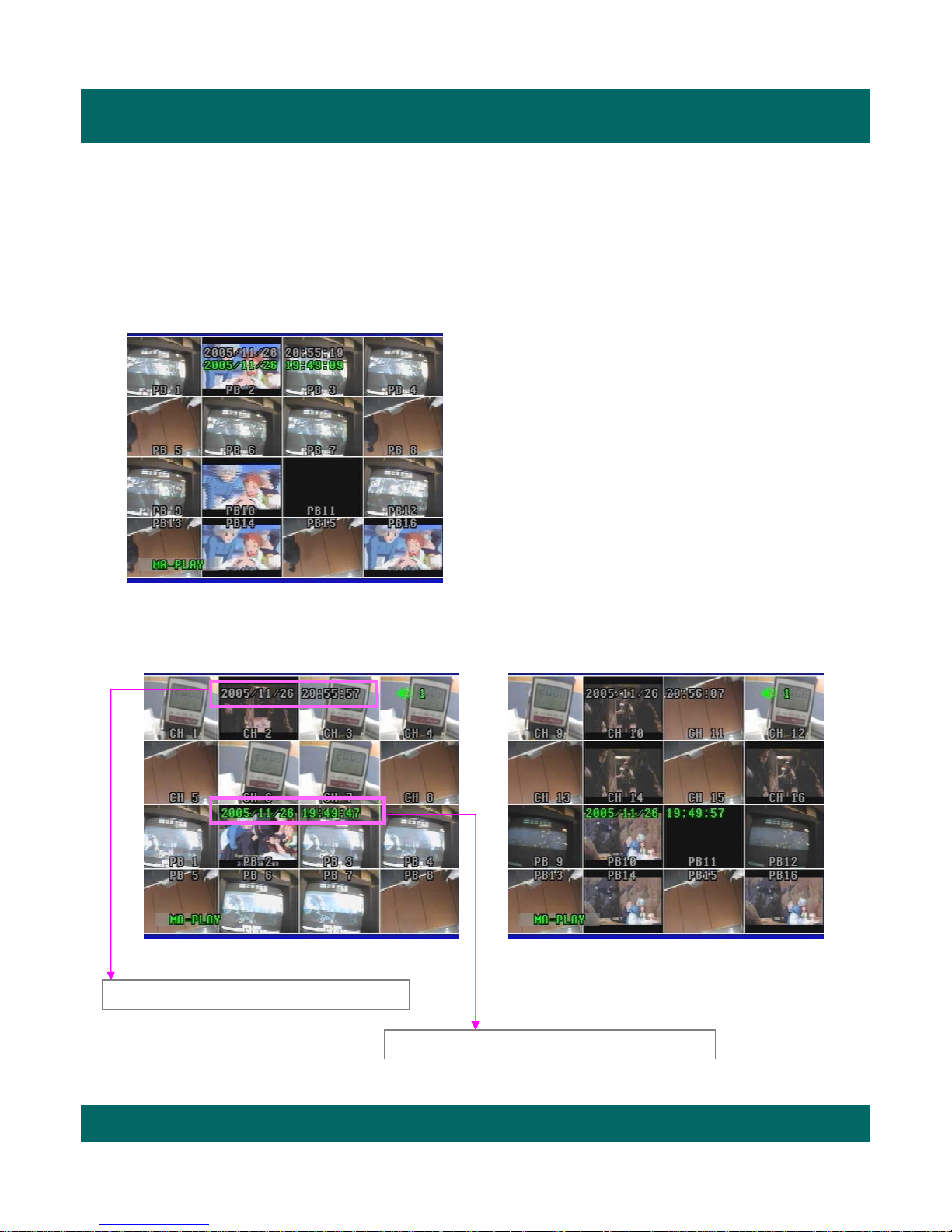
5.2.4 TRIPLEX DISPLAY
You can experience new triplex function (simultaneous recording, playback and network transmission)
with our new line of Digital Video Recorders.
It enables you to convert playback mode to live mode directly without any delay.
- Press TRI button on the front panel in playback mode
and then you will see 8 channel live display mode
and playback mode with each channel 1~8 as below.
- Press TRI button three times repeatedly, it returns to
16ch playback mode.
- To surf the other 8 channel live display and playback
with each channel 9~16, press MULTI button
or Up/Down button in the remote controller.
- If you press channel button in this mode, you can see
the full channel video of playback mode in the screen.
- To exit to live display mode, press MULTI button or
TRI button again.
[ 16CH Playback]
[ Triplex Mode -1] [ Triplex Mode -2]
Date/Time in white means current real-time.
Date/Time in green means playback date/time.
Page 23
Triplex Real Time Stand Alone DVR
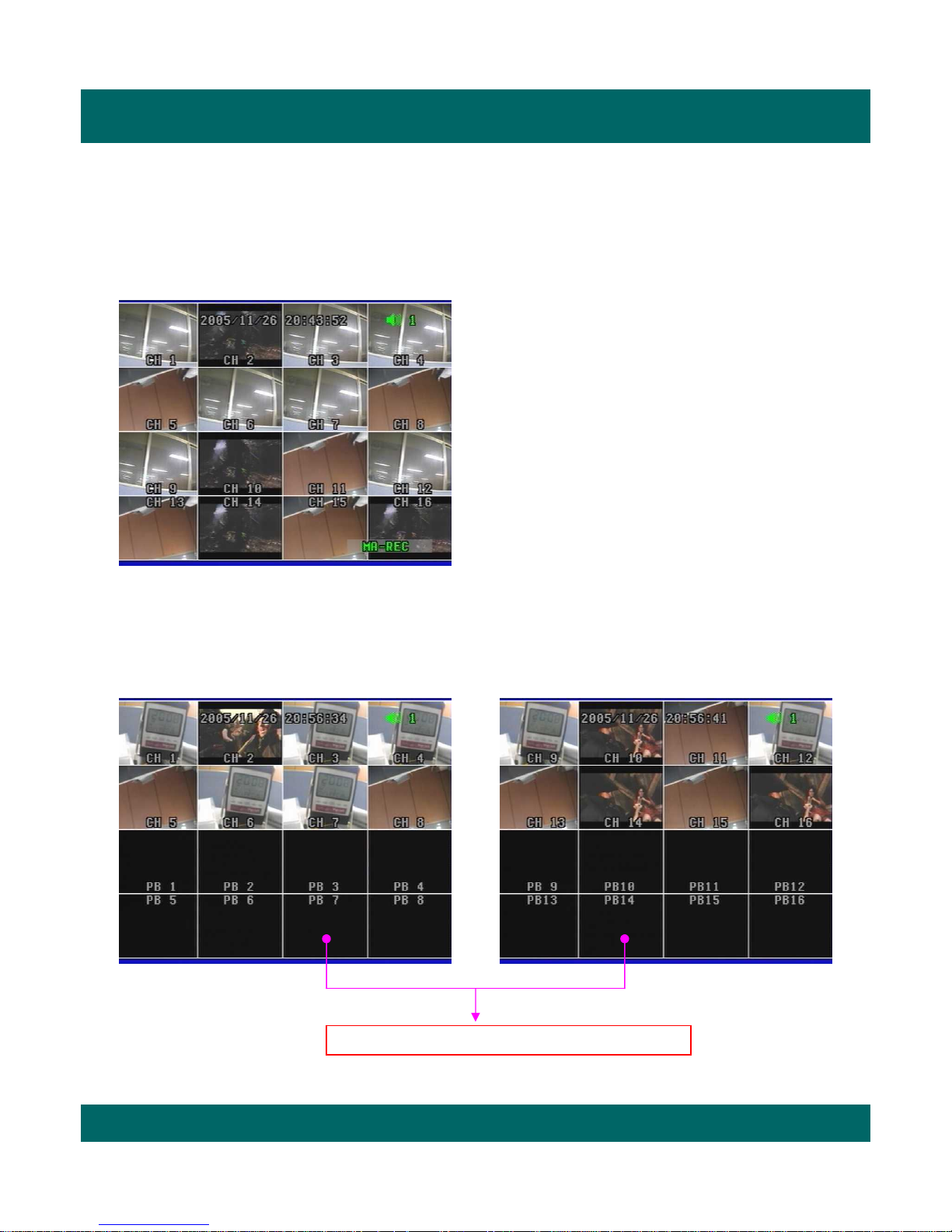
23
- Press TRI button on the front panel in live display
mode with no playback and you will see 8 channel
live display and 8 channel playback with no video as
below.
Because the DVR has no playback videos at that time.
- Press TRI button three times repeatedly, it returns
to 16ch playback mode with no videos.
- To surf the other 8 channel live display and playback
with each channel 9~16, press MULTI button or
Up/Down button in the remote controller.
- To return to live display mode, press Multi button or
TRI button again.
[ 16CH Live Display]
[ Triplex Mode - 1 ] [ Triplex Mode - 2 ]
It shows no videos in black because of no playback.
Page 24
Triplex Real Time Stand Alone DVR
24
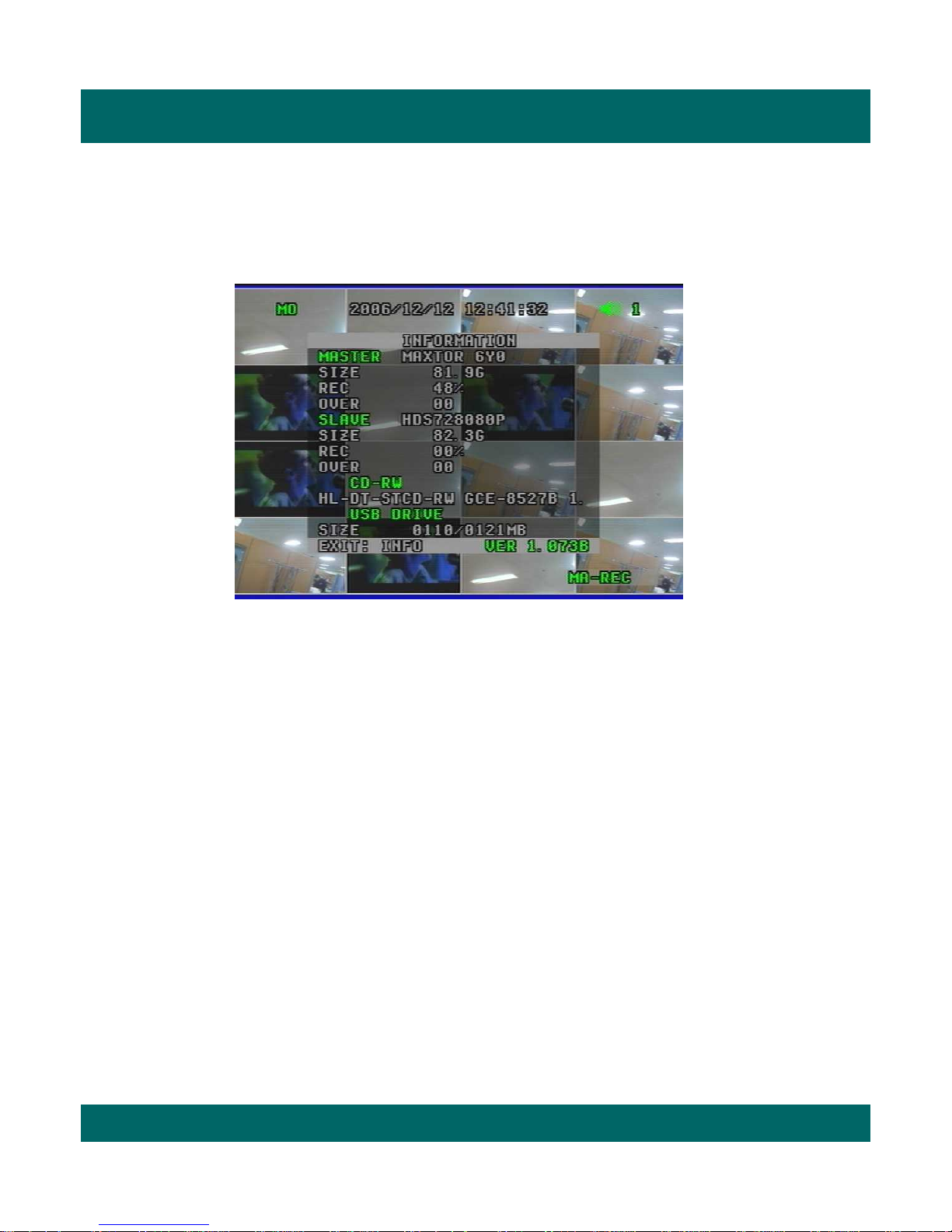
5.2.5 DVR INFORMATION
It shows all information about the DVR system like HDD, CD-RW, USB and software version in live
display mode. You can access to system information easily just by pressing INFO (Information) button.
1) MASTER
- Model : It shows the model no. of Master HDD.
- Size : It shows the size of Master HDD.
- Rec. : It means the capacity of used HDD.
- Over : It means how many times the HDD is overwritten.
2) SLAVE
- Model : It shows the model no. of Slave HDD.
- Size : It shows the size of Slave HDD.
- Rec. : It means the capacity of used HDD.
- Over : It means how many times the HDD is overwritten.
3) CD-RW
- It shows the model no . of CD-RW installed in the DVR.
4) USB DRIVE
- It shows USB detection and USB capacity for data backup in the DVR.
5) Version (VER 1.073B)
- It shows current software version of the DVR.
• To exit from this menu, press INFO (Information) button again.
Page 25

Triplex Real Time Stand Alone DVR
25
5.2.6 RECORD
1
1. If you press REC button on the front panel of the DVR, you will see REC in green on the right bottom of
screen. It means the DVR is in the recording process.
- MA-REC : It records videos in Master HDD.
-SL-REC : It records videos in Slave HDD.
• To release REC function, press REC button again.
2. It indicates that playback function is on in live display mode, which is one of our main features,
that is simultaneous multi-function operation in one screen.
-MA-PLAY :It plays videos that have been stored in Master HDD.
-SL-PLAY :It plays videos that have been stored in Slave HDD.
3. It means that audio function is set to channel 1 (default).
Users can select one channel audio function among 16 channels as they desire.
2
3
* Schedule Record Mode
When Schedule Record Mode is selected, the recording will be automatically executed according
to the recording schedule set by users.
(Please refer to Schedule Setup in Record Setup, page 57.)
Note
Note
Page 26

Triplex Real Time Stand Alone DVR
26
5.2.7 SEARCH & PLAYBACK
With Triplex function, you can enter search menu while the DVR is in recording mode. So you don’t
need to press "STOP" button on the front panel to stop recording.
Now you press SEARCH button on the front panel. You can scroll through recordings using “Up/Down”
button and navigate among pages of the recordings using “Right/ Left” button.
To view a desired recording in the list, press “ENTER” button where the recording is highlighted.
The DVR will playback the recording. You can stop the video at any time by pressing “STOP” button.
5.2.7.1 DATE / TIME LIST SEARCH
1) Press SER button on the front panel.
2) Select “Date/Time List Search” by using Up/Down button and press ENTER button.
3) Select one between MASTER and SLAVE by pressing SER button.
4) Select your desired one in the recording lists and press ENTER button.
5) Check if the list is the right one that you select, and then press ENTER button again.
6) It plays the list.
* To be out of this menu, press MENU button repeatedly.
Page 27

Triplex Real Time Stand Alone DVR
27
5.2.7.2 EVENT LIST SEARCH
1) Press SER button on the front panel.
2) Select “Event List Search” by using Up/Down button and press ENTER button.
3) Select one between MASTER and SLAVE by pressing SER button.
4) Select your desired one in the recording lists and press ENTER button.
5) Check if the list is the right one that you select, and then press ENTER button again.
6) It plays the list.
* To be out of this menu, press MENU button repeatedly.
5.2.7.3 DATE/TIME SEARCH
1) Press SER button on the front panel.
2) Select “Date / Time Search” by using Up/Down button and press ENTER button.
3) Select one between MASTER and SLAVE by using ENTER button.
4) Type in specific date/time upon your desired list by pressing Up/Down button
and press ENTER button.
5) It plays the list.
* To be out of this menu, press MENU button repeatedly.
Page 28

Triplex Real Time Stand Alone DVR
28
5.3 REMOTE CONTROLLER
1. REC (Record)
2. Mute
3. CH1~CH10 (Channel selection)
4. Zoom (2x2 digital zoom)
5. INFO (Information)
6. MENU
7. Multi
8. PIP
9. Auto (Sequence)
10 ◀ Left
11 ▲ Up
12 ▶ Right
13 ▼ Down
14. ENTER
15. All (Search menu)
16. Time (Search by date/time)
17. List (Search by dat e/time list)
18 ■ Stop
19. REW (x2, x4, x8, x16 rewind)
20. FF (x2, x4, x8, x16, x32, x64 fast forward)
21 ▶Play
22. II Pause
23. P.B (Playback)
24. TRI (Triplex)
25. Panorama
26. P/T (Pan/Tilt)
27. Z/F (Zoom/Focus)
28. CD-RW Backup
29. USB Backup
5.3.1 REMOTE CONTROLLER FUNCTIO NS
3
45
6
78
9
10
11
12
13
15
23 24
16 17
25
26
14
18
19 20
21
22
27
12
28 29
Page 29

Triplex Real Time Stand Alone DVR
29
5.3.2 MUTE
When you’d like to make the video with audio silent, you can select MUTE function in the remote
controller.
1) Press MUTE button in the remote controller when monitoring (or playing) the video with audio.
2) The activated icon in green in the upper right of screen is changed to one in gray with this function.
3) The DVR makes it silent.
* To release this function, press MUTE button again.
Page 30

Triplex Real Time Stand Alone DVR
30
5.3.3 DIGITAL ZOOM
1) Select the desired channel among 16 channels.
2) Press Zoom button in the remote controller.
3) Select the target area by pressing Left/Right/Up/Down
button in the remote controller .
And then press Zoom button again.
4) You can see the video that is magnified two times digitally.
5) To exit this mode, push Zoom button again
in the remote controller.
You can magnify a certain part of the full size screen two times digitally when you use this function
as described below. This function can be applied to all display and search modes.
You can operate this function with only remote controller.
It indicates Digital Zoom fun cti on.
Page 31

Triplex Real Time Stand Alone DVR
31
5.3.4 PANORAMA
This function enables you to monitor each channel with 16 split-channel panorama mode in the screen.
It is available only in playback mode.
1) Select and play your desired video in the recording list first.
2) Press PANORAMA button in the remote controller.
3) Select your desired channel by pressing PANORAMA button repeatedly.
4) To exit this function, press MULTI button.
* Press PANORAMA button again in PANORAMA mode and you will return to playback mode.
To be out of playback mode, press STOP button.
Note
Note
Page 32

Triplex Real Time Stand Alone DVR
32
5.3.5 PTZ CONTROL
To control an external Pan/ Tilt/ Zoom/Focus camera,
1. First, press P/ T button in t he remote controller.
2. Select your desired channel by pressing channel selection button directly.
3. Control the camera with the direction buttons (Up/ Down/ Right/ Left).
4. To release this function, press P/T button again and then “P/T” disappears on the screen.
5.3.5.1 Pan/ Tilt Function
1) 16 channel display mode
2) One channel Mode
It indicates Pan/Tilt function.
1. First, select your desired channel installed in Pan/Tilt camera by pressing channel selection button.
2. And then you will see a full-size screen.
3. Press P/T button in the remote controller.
4. Control the camera with the direction buttons (Up/ Down/ Right/ Left).
5. To release this function, press P/T button again in the remote controller.
It indicates Pan/Tilt function.
Page 33

Triplex Real Time Stand Alone DVR
33
2) One channel mode
1. First, select your desired channel installed in Zoom/Focus camera by pressing channel selection button.
2. And then you will see a the full-size screen.
3. Press Z/F button in the remote controller.
4. Control the camera with the direction buttons (Up/ Down/ Right/ Left).
5. To release this function, press Z/F button again in the remote controller.
It indicates Zoom Focus function.
1. First, press Z/ F button in the remote controller.
2. Select your desired channel by pressing channel selection button directly.
3. Control the camera with the direction buttons (Up/ Down/ Right/ Left).
4. To release this function, press Z/F button again and then “Z/F” disappears on the screen.
5.3.5.2 Zoom/ Focus Function
1) 16 channel display mode
It indicates Zoom Focus function.
Page 34

Triplex Real Time Stand Alone DVR
34
1. Insert a blank CD into CD-RW of DVR.
Select your desired list and play it.
Press “Backup” button and select “CD-RW” as left.
It shows current time and recording time on the screen.
2. Press Enter button.
It pauses playback mode and shows “CD-RW backup checking”
on the screen, which may take some time to complete “Checking”.
3. It indicates that it is ready for CD-RW backup mode
showing “Ready” on the screen to users.
Press Enter button and then it starts CD-RW backup
showing “Setting” on the screen.
5.3.6 BACKUP
5.3.6.1 CD-RW BACKUP
Page 35

Triplex Real Time Stand Alone DVR
35
4. It burns CD showing “Burning” on the screen.
It updates stop time and recorded CD capacity as it burns CD
with data.
You can stop the burning by pressing backup button
(or CD backup button in the remote controller) at any time
as you want.
5. It stops burning CD showing “Stopping - Closing” on the screen
after completing it.
It pauses playback mode.
7. To get out of this mode, press backup button.
And press Play button and then it plays the list continuously
right from the pause point.
To return to live display mode, press “Stop” button.
6. The burned CD comes out automatically from CD-RW
showing “Close” on the screen.
In case that the list size is bigger than blank CD capacity,
you can continue to backup the remained size with another
blank CD.
Î Insert new one into DVR and press Enter button.
It continues to backup the remained size of the list.
Note
Note
How to play the data in the CD
You can play the data in the CD only using “network viewer”
program provided in the package.
For further details, please refer to page 76.
Note
Note
For your reference, it usually takes max. 30 minutes
to burn 700MB blank CD.
Note
Note
Page 36

Triplex Real Time Stand Alone DVR
36
5.3.6.2 USB BACKUP
1) Video File Backup
1. Insert USB memory stick into USB port on the front panel of DVR.
It takes 4~5 seconds to detect it.
You can check in the “Information” menu if DVR detects it or not.
2. Select the desired recording list and play it.
It plays the list in CIF mode as left.
3. To operate USB backup function, press Backup button
in the front panel (or USB button in remote controller) at your
convenience.
Select USB and then press Enter button.
USB stick memory format in your PC
You have to format it by only “FAT 32” as file system.
Note
Note
Page 37

Triplex Real Time Stand Alone DVR
37
4. It pauses playback mode and shows “USB backup checking”
on the screen, which may take some time to complete “Checking”.
5. It indicates that it is ready for USB backup mode
showing “Ready” on the screen.
6. Press Enter button and then it starts USB backup
showing “Backup” on the screen.
It updates stop time and recorded USB capacity as it stores the data
in the USB memory stick.
You can stop the USB backup by pressing backup button
(or USB backup button in the remote controller) at any time
as you want.
7. To stop it, press Backup button (or USB in remote controller) again.
It stops USB backup showing “Close” on the screen.
And it pause playback mode.
It may take some time.
DVR may be shut down if you remove USB memory
stick in the process of backup.
Note
Note
Page 38

Triplex Real Time Stand Alone DVR
38
9. You can find the file in USB memory stick.
M 051121 091025 0001.dvr
- M means video file.
- 051121 means year / month / day.
- 091025 means hour / minute / second.
- 0001 means file counting number.
- .dvr means that the file is recorded by MJPEG compression.
How to play the file in USB memory stick
You can play the file in USB memory stick
by using only “network viewer” program to be provided
in the package.
For further details, please refer to page 75.
Note
Note
- If you remove USB stick in the process, DVR may be shut
down (or in crash).
CAUTION !
CAUTION !
8. To get out of this mode, press backup button.
And press Play button and then it plays the list continuously
right from the pause point.
To return to live display mode, press “Stop” button.
E0511210910250001.dvr
- E shows that some errors happen in the process of
backup, which users cannot play it due to file error.
Note
Note
Page 39

Triplex Real Time Stand Alone DVR
39
2) Still Image Copying
1. Insert USB memory stick into USB port on the front panel of DVR.
It takes 4~5 seconds to detect it.
You can check in the “Information” menu if DVR detects it or not.
2. Select the desired recording list. It plays the list in CIF mode.
And then select one channel that you want.
3. Press Backup button in the front panel
(or USB button in remote controller) at your convenience.
“USB STILL” is displayed and disappeared on the bottom of screen.
USB memory stick starts storing it
showing that the LED of USB stick flickers.
USB stick memory format in your PC
Users have to format it by only “FAT 32” as file system.
Note
Note
Page 40

Triplex Real Time Stand Alone DVR
40
4. After ”USB STILL” is disappeared on the bottom of screen,
you can continue to do it by pressing Backup button on the front panel
of DVR (or USB button in remote controller) repeatedly.
You can continue to do still image copying
by pressing Backup button repeatedly
(or USB button in remote controller) as you want.
DVR may be shut down if you press the button repeatedly
before “USB STILL” is disappeared on the screen.
How to play the file in USB memory stick
You can play the file in USB memory stick
by using only “network viewer” program to be provided
in the package.
For further details, please refer to page 75.
Note
Note
1. If you remove USB memory stick in the process of backup,
DVR may be shut down (or in cra sh).
2. You cannot store still images in USB memory stick
in the pause mode of playback.
CAUTION !
CAUTION !
5. You can find the file in USB memory stick.
S 051121 091025 0001.dvr
- S means still image file.
- 051121 means year / month / day.
- 091025 means hour / minute / second.
- 0001 means file counting number.
- .dvr means that the file is recorded by MJPEG compression.
E0511210910250001.dvr
- E shows that some errors happen in the process of
backup, which users cannot play it due to file error.
Note
Note
Page 41

Triplex Real Time Stand Alone DVR
41
CHAPTER 6. SETUP MENU
6.1 Language
• When you first call the main menu via the MENU button, you’ll see that the current language is
highlighted (see screen shot above).
• To exit to main menu, press MENU button.
Page 42

Triplex Real Time Stand Alone DVR
42
6.2 System Setup
1) Overwrite ON/OFF
To enable (ON) or disable (OFF) to overwrite HDD.
2) Record OSD ON/OFF
To show “REC” in green in the right bottom of screen during recording mode.
-“MA-REC“ shows videos are recorded in master hard disk.
-“SL-REC” shows videos are recorded in slave hard disk.
3) Format
To format the HDD, press ENTER button and then select YES.
• To return to main menu, press MENU button.
6.2.1 HDD Setup
This menu enables HDD setup.
Note
Note
You have to make sure of it before HDD format.
Once HDD formatted, yo u are not able to retrieve any video that has
been recorded previously.
Page 43

Triplex Real Time Stand Alone DVR
43
1) Select ON/OFF
To enable (ON) or disable (OFF) a password.
2) Input ****
To type in your desired 4 digit password among 0~9 by pressing ENTER & direction button.
To return to the sub menu, press MENU button after completing password input.
• To return to main menu, press MENU button.
6.2.2 Password Setup
This menu allows to choose system password.
Remember that the password is set to 1111 as factory default.
Note
Note
Page 44

Triplex Real Time Stand Alone DVR
44
6.2.3 Channel Name Setup
To make camera names easy to remember, you can assign na mes to individual channels up to 8
characters per channel. For example, if your one external camera is located in a factory, you can
name it as “factory”. You can see videos with this name on the screen during operation.
1) Live ON/OFF
2) PB ON/OFF
- When turned ON, it enables display of camera names in playback mode.
- When turned OFF, it disables display of camera names in playback mode.
3) CH 1 ~ CH 16 ■■CH ■1/2/…/16 ■■
- When the pointer is located next to CAMERA1/2/3/4…/14/15/16,
1. Press ENTER button.
2. See the active cursor on the first letter of ■ which means a blank.
3. Surf along letters by pressing Up/Down button.
4. When you find your desired letter, press Right/Left button to move the active cursor to the next
letter.
5. After the naming process is completed, press MENU button and then press Up/Down button
to move to other cameras.
To return to main menu, press MENU button.
Page 45

Triplex Real Time Stand Alone DVR
45
6.2.4 Date/ Time Setup
Everybody agrees that surveillance digital video recorders must indicate the exact date and time
information in which an event took place in order to be used as an evidence. Therefore, configuring
the DVR to correct time and date is very important.
.
1) Live ON/OFF
2) PB ON/OFF
- When turned ON, it enables display of date/time in playback mode.
- When turned OFF, it disables display of date/time in playback mode.
3) Type YY/MM/DD, DD/MM/YY, MM/DD/YY
4) Date 2005/05/11
5) Time 20:51:49
- When the pointer is located next to Date or Time,
1. Press ENTER button
2. Set Date or Time
- To Select it by pressing Up/Down button
- To Move to the next by pressing Left/Right button
3. When you finish setting Date/ Time, press MENU button and then press Up/Down button
to move to other sub menu.
To return to main menu, press MENU button.
Page 46

Triplex Real Time Stand Alone DVR
46
6.2.5 Beep & PTZ Setup
This menu enables recording beep and external Pan/ Tilt & Zoom/ Focus cameras setup to
communicate with.
1) PAN / TILT Hitron / LG / Dongyang / PELCO-P / PELCO-D / COP1 / COP2
To select a desired protocol which is used for communication between the external Pan/ Tilt camera
and the DVR set.
2) PTZ Speed 1 ~ 5
To select PTZ camera speed among 5 levels.
Lower level makes the camera speed slower.
3) Baud Rate 2400 BPS ~ 12400 BPS
Users can select Baud rate to be in accordance with one of installed cameras.
For example, if you install a camera with the protocol of “PELCO-P 4800”, you have to select
PTZ type as “PELCO-P” and baud rate as 4800 BPS (Bits Per Second).
Compatible Pan/ Tilt camera list
- All cameras using LG, Hitron, Dongyang protocol.
- PELCO-D, PELCO-P
Note
Note
4) Record Beep ON/OFF
To enable recording beep when pressing REC button to start and release the function.
Page 47

Triplex Real Time Stand Alone DVR
47
6.2.6 System Reset ON/OFF
To reset the system, press Enter button and select YES.
You have to make sure of it before system reset.
Once system reset, all data that you had selected previously are
converted to factory mode including password.
• To return to main menu, press MENU button.
5) HDD Fail ON/OFF
To enable to beep when the DVR detects a bad sector of HDD in recording mode or playback mode.
It skips the bad sector detected and records videos or plays recorded videos in the next sector
of bad sector automatically.
HDD is logically divided to a large amount of sectors. It may have some bad sectors out of alarge
amount of it. When this function is on, you are recommended to exchange with new one in order to
preventing from any potential problems caused by the HDD with bad sectors.
• To return to main menu, press MENU button.
Page 48

Triplex Real Time Stand Alone DVR
48
6.3.1 Blank Channel Setup
To enable to make channels hidden behind the screen during live display mode as below.
CH 1 ~ CH 16 ON/OFF
To return to main menu, press MENU button.
6.3. Display Setup
Even though some channels are hidden behind the sc re en during live
display mode, DVR is recording them in HDD.
Note
Note
Page 49

Triplex Real Time Stand Alone DVR
49
Main CH 1 ~ CH 16
Sub 1 CH 1 ~ CH 16
Sub 2 CH 1 ~ CH 16
Sub 3 CH 1 ~ CH 16
To define which channel is the main channel for full screen or sub channel among 16 channels.
• To return to main menu, press MENU button
6.3.2 PIP Channel Setup
You can select PIP ( Picture In Picture ) options. PIP mode offers a convenient way of monitoring
multiple channels while focusing more attention on a particular channel. It has a main video channel
view and up to 3 small video channel views on the screen.
Page 50

Triplex Real Time Stand Alone DVR
50
6.3.3 Adjust Channel Setup
This menu allows to opt color adjustment for individual cameras.
1) Channel CH1 ~ CH 16
- To select your desired channel to adjust video display.
2) CON (Contrast) 50
- To control light and shade of video display.
3) HUE 50
- To control color tone of video display.
4) BRI (Brightness) 50
- To control brightness of video display.
5) COL (Color) 50
- To control saturation of color of video display.
• To return to main menu, press MENU button.
Default factory mode is s et to 50.
Remember that the values range is from 01 to 99.
Note
Note
Page 51

Triplex Real Time Stand Alone DVR
51
6.3.4 Video Signal Type NTSC / PAL
To select your local video signal type between NTSC and PAL, press Enter button and select it.
It reboots the system automatically after your selection.
It reboots the system automatically after your selection.
Once it reboots, all data that you had selected previously is set to factory default.
6.3.5 Sequence 1 sec ~ 1 min
To select interval time of Auto Switch.
With the Auto Sequence feature, a range of interval time among some different views can be
selected.
“AUTO” mark in the left top of screen indicates “(Auto) Sequence” mode .
In this mode, it may skip the channels with no video.
• To return to menu, press MENU button.
Page 52

Triplex Real Time Stand Alone DVR
52
6.3.6 Boundary White/Black/OFF
To select the boundary color that is divided into each channel.
6.3.7 Blank Blue/Black
To select the background color of no video channels between two colors.
• To return to menu, press MENU button.
Page 53

Triplex Real Time Stand Alone DVR
53
6.4. Event Setup
This screen enables simple set up of DVR motion detection, alarm and external sensor configurations.
6.4.1 REC Time 3 sec ~ 30 min
Once event recording is triggered, the video will be recorded compulsorily during the time
selected by the user or administrator.
6.4.2 Sensor In N.O/N.C
The Sensor-in terminals of the DVR ar e used to connect external motion sensors or door/window
contacts.
There are two types of general sensors in the market. The one is "normal mode-open“, N.O, wh ich
means two sensor lines are not connected (open) in the normal mode but the lines are to be
connected (close) in the activation mode. The other is "normal mode-close“, N.C, which means two
sensor lines are connected (close) in the normal mode but the lines are to be disconnected (open)
in the activation mode.
• To return to menu, press Menu button.
You have to make sure of sensor type between N.O and N.C
before installation. Otherwise, it may not work properly.
- N.O : Normal Open type sensor
- N.C : Normal Close type sensor
Page 54

Triplex Real Time Stand Alone DVR
54
1) Alarm Out ON/OFF
You can set to enable (ON) or disable (OFF) the outbound signal from the DVR.
2) Sensor BEEP+OSD/ OSD/ OFF
When DVR detects signals from external sensors, DVR will beep or OSD to get your attention.
- BEEP + OSD : Beeps and shows “AL” mark together in the channel with video loss.
- OSD : On-Screen-Display only
- OFF : Disables to activate the alarm action
3) Video Loss BEEP+OSD/ OSD/ OFF
If video signals from the cameras do not reach the DVR, a beep will sound to get your attention.
- BEEP+OSD : Beeps and shows “L” mark together in the channel with video loss.
- OSD : On-Screen-Display only
- OFF : Disables to activate the alarm action
4) Motion BEEP+OSD/ OSD/ OFF
When DVR detects motion on a certain part of the screen, DVR will beep or OSD to get your
attention.
- BEEP + OSD : Beeps and shows “MO” mark together in the channel with video loss.
- OSD : On-Screen-Display only
- OFF : Disables to activate the alarm action
• To return to main menu, press MENU button
6.4.3 Event Action
To select notice method in order to make users get more attention when event recording occurs.
Page 55

Triplex Real Time Stand Alone DVR
55
1) Channel CH1~CH16
You must manually set each channel for the motion detection area. Select a channel for this motion
detection.
2) Sensitivity 1~15
It offers 1 to 15 level of sensitivity. Remember that the higher level is more sensitive to detect
motions.
3) Area OFF/ FULL/ SET
- OFF : Disable to select motion areas.
- FULL : Select full area as motion area.
- SET : To select the area as you desire, move to POSITON menu.
4) Position
- Press Enter button and surf areas in the desired channel by pressing direction button and then
press ENTER button to select, press it again to release.
- Once you select the areas, you don’t need to select them again when you get back from
other modes like OFF or FULL. It gives you easy-operation.
• To return to main menu, press MENU button
6.4.4 Motion Setup
This menu enables users to set motion functions.
Page 56

Triplex Real Time Stand Alone DVR
56
6.5. Record Setup
Here you can set recording options.
6.5.1 Type E ACH/ CIF
There are two recording modes: Each and CIF.
If you set it to Each mode, DVR records the full size videos of 16 different channels.
If you set it to CIF mode, DVR records 16 video channels in CIF resolution.
6.5.2 Rec. Speed 1~60 F/S (EACH mode) / 120F/S (CIF mode, Fixed)
You can select various recording speed in field per second (F/S).
60 F/S in each mode means that it records 60 images per second.
Rule of thumb is that higher field per second requires more HDD space.
Depending on NTSC or PAL mode, range of fps available varies.
NTSC and PAL have the following fps available:
- NTSC : 1~60 F/S (Each Mode) / 120 F/S (CIF Mode)
- PAL : 1~50 F/S (Each Mode) / 100 F/S (CIF Mode)
6.5.3 Quality Level 1~6
It is to set video quality from level 1 to level 6.
The higher the video quality, the more HDD space needed.
High quality has lower network tran smission due to image size.
6.5.4 PB Speed AUTO, 1~60 F/S (EACH mode) / 120F/S (CIF mode, Fixed)
You can select various recording speed in field per second (F/S).
“AUTO” (Default) means that it plays videos at the same rate of recording speed.
60 F/S in each mode means that it plays 60 images per second.
Depending on NTSC or PAL mode, range of fps available varies.
NTSC and PAL have the following fps available:
- NTSC : 1~60 F/S (EACH mode) / 120 F/S (CIF mode)
- PAL : 1~50 F/S (EACH mode) / 100 F/S (CIF mode)
Page 57

Triplex Real Time Stand Alone DVR
57
6.5.5 Channel Enables CH1 ~ CH16 (EACH mode) / Group 1~Group 4 (CIF mode)
- ON : Enable to record the channels
- OFF : Disable to record the channels
- Each group indicates each 4 channels. (For example, group 1 shows CH1 ~ CH4.)
6.5.6 Audio Setup
1) Channel CH1~CH16
It is to select one audio channel among 16 channels.
2) (Icon) Display ON/OFF
To enable icon of audio function in the upper right of screen as below.
6.5.7 Schedule Setup
1) Schedule ON/OFF
To disable (OFF) or enable (ON) Schedule recording feature.
2) Day Daily/ SUN~SAT
Select the desired day for schedule recording.
- Daily, Sun, Mon, Tue, Wed, Thu, Fri, Sat
3) Time
When you finish to set Day, press ENTER button to go into the Timeline. Surf left or right in the
timeline by pressing Left or Right button. If you find a desired time for schedule recording,
press Up button to set or Down button to release.
To return to main menu, press MENU button.
Page 58

Triplex Real Time Stand Alone DVR
58
6.6 Network Setup
To monitor and control videos remotely through internet, you need to have the right set up.
6.6.1 IP Address *000.000.000.000
Type in the IP address of your DVR.
6.6.2 Subnet Mask *000.000.000.000
Type in the Subnet mask number.
6.6.3 Gateway *000.000.000.000
Type in the Gateway number.
6.6.4 Bypass ON/OFF
- ON : The videos are transferred directly not through memory,
which means that it may display abnormal videos in network viewer.
- OFF : The videos are transferred through memory, which means that it checks abnormal videos.
It is recommended as “Bypass - OFF”.
6.6.5 Sequence Internet / Ethernet
- Internet : The videos are displayed in network viewer according to the order of transferred videos.
“Internet” updates videos faster than “Ethernet”.
- Ethernet : The videos are displayed in network viewer from channel 1 in sequence.
“ Ethernet” doesn’t update channel 2 until channel 1 is displayed.
6.6.6 Network ID ******** ( 8 letters)
6.6.7 Password ******** ( 8 letters)
You must register your Network ID before us ing network viewer program first.
Press Enter button and type in network ID & Password by pressing direction button.
To access to network viewer program, you need to type in the ID & Password for log-in.
• To return to main menu, press MENU button
To check Mac. Address, Server IP Address & Port number (default : 5000),
press CH4 button in network setup menu.
The main reason of hidden Mac. address & DDNS server IP menu is just f o r
security in order to prevent from being changed without user’s approval.
Note
Note
1. we would like to recommend you to check your local Firewall or personal
network security programs. Sometimes they block certain ports for network
security purpose.
2. If you don’t have right information about network, please contact your
network administrator.
Page 59

Triplex Real Time Stand Alone DVR
59
CHAPTER 7. EXTERNAL TERMINAL INFORMATION
7.1 RS-232
[ 16CH DVR ]
12345
6789
N/C
TX 232C
RX 232C
N/C
GND
6 ~ 9 N/C
* N/C : Connection Not Required
Description
2
3
4
5
1
No
RS-232
Page 60

Triplex Real Time Stand Alone DVR
60
[ 4CH DVR ]
[ 8CH DVR ]
RS-232 & Alarm In/Out & RS-485
123456789101213 11
14151617182021222325 24 19
Alarm In
GND
RX 232C
TX 232C
GND
21
Alarm Out COM
22
Alarm Out NO
8CH DVR
9 ~ 14
15
16
17 ~ 20
1 ~ 8
No
Alarm In
GND
RX 232C
TX 232C
GND
24
485A
25
485B
4CH DVR
5 ~ 14
15
16
17 ~ 20
1 ~ 4
No
23
Alarm Out NC
24
485A
25
485B
21
Alarm Out COM
22
Alarm Out NO
23
Alarm Out NC
Page 61

Triplex Real Time Stand Alone DVR
61
7.2 ALARM IN/OUT & RS-485
[ 16CH DVR ]
Alarm In/Out & RS-485
123456789101213 11
14151617182021222325 24 19
Alarm In
GND
Alarm Out COM
Alarm Out NO
Alarm Out NC
24
485A
25
485B
Description
17 ~ 20
21
22
23
1 ~ 16
No
Page 62

Triplex Real Time Stand Alone DVR
62
[ 4CH DVR ]
[ 8CH DVR ]
RS-232 & Alarm In/Out & RS-485
123456789101213 11
14151617182021222325 24 19
Alarm In
GND
RX 232C
TX 232C
GND
21
Alarm Out COM
22
Alarm Out NO
8CH DVR
9 ~ 14
15
16
17 ~ 20
1 ~ 8
No
Alarm In
GND
RX 232C
TX 232C
GND
24
485A
25
485B
4CH DVR
5 ~ 14
15
16
17 ~ 20
1 ~ 4
No
23
Alarm Out NC
24
485A
25
485B
21
Alarm Out COM
22
Alarm Out NO
23
Alarm Out NC
Page 63

Triplex Real Time Stand Alone DVR
63
7.3 VGA (Optional)
[ 16CH DVR ]
[ 4CH DVR ]
[ 8CH DVR ]
12345
6789
10
1112131415
14
15
Description
2
3
4 ~ 12
13
1
No
VSYNC (Vertical Sync.)
Reserved
GREEN (Green Video [75ohm, 0.7Vp-p])
BLUE (Blue Video [75ohm, 0.7Vp-p])
Reserved
HSYNC or CSYNC (Horizontal or Composite Sync.)
RED (Red Video [75ohm, 0.7Vp-p])
Page 64

Triplex Real Time Stand Alone DVR
64
7.4 ETHERNET & USB
[ 16CH DVR ]
1) USB
2) ETHERNET
Description
2
3
4
1
No
USB DATA -
USB DATA +
GND
VCC
6
7
Description
2
3
4
5
1
No
RX+ (Receive Data+)
TX- (Transmit Data-)
N/C (Not Connected)
RX- (Receive Data-)
N/C (Not Connected)
N/C (Not Connected)
N/C (Not Connected)
1) USB
2) ETHERNET
8 TX+ (Transmit Data+)
Page 65

Triplex Real Time Stand Alone DVR
65
Specifications
Category
NTSC/PAL, 1V 75 Ohm, BNC (4, 8 and 16CH), Auto-loop throughout
Input
4CH DVR
Video
Signal
Real-time full duplex M-JPEG codec core
CHAPTER 8. SPECIFICATIONS
Output
CVBS, S-Video, VGA (optional)
Audio
Input / Output
Recording Mode
2 X RCA (1CH Input , 1CH Output)
Mono PCB 8KB / sec
120 / 100 FPS 240 /200 FPS 480 / 400 FPSDisplay FPS (NTSC/PAL)
720 X 480 (NTSC) / 720 X 576 (PAL)
Display Resolution
Screen Split Mode
Full, Quad, Split and 3 PIPs
Zoom Mode
2 X 2 Digital Zoom
Display
Triplex Mode
Simultaneous Recording / Playback / Live / Network
Video Compression
Video Resolution
720 (360) X 480 (NTSC) / 720 (360) X 576 (PAL)
Recording Ways
Continuous, Scheduled, Event (internal motion, external sensor)
Recording FPS
NTSC : 120 FPS / PAL : 100 FPS
Image File Size
NTSC : 3 ~ 25 KB / PAL : 4 ~ 27 KB
EIDE, ATA-100, MAX 2 HDDs supported, Unlimited HDD Capacity
Internal Hard Drives
Recording
Remote access through Internet
Remote monitoring via network viewer program
Playback Mode
Playback Screen Mode
Search Ways
Zoom Mode
Live & Playback, Playback, Panorama
Full, Quad, PIP, Zoom, Split, Panorama
Search by Date/ Time List, Event List & Date/Time
Digital 2 x Zoom ; Playback available in Zoom Mode
Playback
External Alarm Input
Alarm Input : NO, NC Type
Alarm Output
Internal Buzzer, OSD, Internal Relay (Combined with External Device)
30 sec ~ 30 min
Alarm Setup Period
Alarm
Control
TCP / IP ; RJ-45
Protocol
Resolution
720(360) X 480 (NTSC) / 720(360) X 576 (PAL)
Remote Control
Functional remote client software
Browser
Own Application provided
Recording
Motion Picture, Event, Manual Recording
Network
Data Backup
Ethernet, CD-RW, USB
Switching Period : 1 ~ 60 sec
Automatic Alarm
Display Hidden Function by Each Channel ; Recording Available
IR Remote Control, RS-485 / RS-232
12V 5.0 A DC Adaptor (AC 100V ~ 240V, AC 50~60Hz Input)
17.0” X 14.1” X 3.0” (430 x 360 x 75 mm)
FCC, CE
Others
Auto Screen Switching
Approval
Weight
Signal Loss Detection
Display Hidden Function
Remote Control
Power Supply
Dimension
6.3 kg 6.5 kg 6.7 kg
16CH DVR8CH DVR
Page 66

Triplex Real Time Stand Alone DVR
66
Unscrew the both sides and rear of the DVR
and then remove the top cover.
9-1. HDD INSTALLATION
CHAPTER 9. HDD & CD-RW INSTALLATION
1
Install the HDDs on the HDD plate and screw as left.
2
3
Close the top cover and screw and turn on the power.
4
5
HDD Jumper Setting Information
Before installing the Hard Disk Drives, please read the jumper
setting information on the label. If the jumper is not set properly,
the system will be disordered.
* Check if HDD has no pro blem after HDD installation bec ause
record function may not work well due to HDD problem.
* It may reboot automatically when HDD has problems
or it doesn’t detect HDD.
* Contact your local distributor and exchange with new one
when you find your HDD has a problem.
Make sure that the HDDs are set t o “Master”& “Slave” properly
and then connect the power cable and IDE cable as left.
Fix HDDs to rack mount by screwing as left.
Page 67

Triplex Real Time Stand Alone DVR
67
9-2. CD-RW INSTALLATION
Unscrew the both sides and rear of the DVR
and then remove the top cover.
1
Install the CD-RW on the CD-RW plate and screw as left.
2
3
Close the top cover and screw and turn on the power.
4
5
Connect the power cable and IDE cable as left.
Fix CD-RW to rack mount by screwing as left .
Page 68

Triplex Real Time Stand Alone DVR
68
CHAPTER 10. CLIENT NETWORK VIEWER MANUAL
10.1 SYSTEM REQUIREMENT
- Pentium III or above recommended
- O/S : Microsoft Windows 2000 / XP
- 256MB RAM or above recommended
- Super VGA 16M or above recommended
- 10/100 Base T network card for LAN operation
10.2 NETWORK ENVIRONMENT
Recommend
(16 Frames/sec)
Client PC DVR
Minimum
More than 3 Mbps More than 3 Mbps
More than 1 Mbps More than 0.5 Mbps
* Transfer rate of image varies with the number of client accessing to DVR.
10.3 NETWORK VIEWER INSTALLATION
• To start network viewer installation,
1. Start Windows 2000 or XP.
2. Insert install CD into the CD-ROM drive.
3. Install the network viewer and then the shortcut icon is located on your PC screen.
4. Simply double-click the icon to start.
5. The network viewer will appear on the screen as below.
Page 69

Triplex Real Time Stand Alone DVR
69
10.4 NAMES & FUNCTIONS
No Names Description
1 Connect / Pause
Connect to DVR server or Pause
2 Reverse Step Play
Play videos reversely frame by frame
3 Forward Step Play Play videos forwardly frame by frame
4 Start point of File Move to the start point of the recording list
5 End point of File Move to the end point of the recording list
6 Channel Selection Select a channel
8 Log-in
Log in network viewer to the DVR server
7 Operation Mode
Select operation mode
9 Display Mode
Select display mode
1
23 45 6
7
8
9
10
12
11
14
15
13
10
16 17
Page 70

Triplex Real Time Stand Alone DVR
70
10
DVR
Show that the DVR is remotely operated
AVI
Show that storing the video by AVI file format is on
Local Show that storing the video by MJPEG format is on
Connect Show that network viewer is connected
Disconnect Show that network viewer is not connected
Reading Show that the network viewer is reading data from the DVR
12 Local
Store the video by MJPE G format
11 Close
Close the network viewer
13 AVI
Store the video by AVI f ormat
14 Setup
Type in DVR IP address
Default directory is as below.
1. AVI file : “C” drive > “dvr” folder
- Users can select a directory as they desire in setup menu.
2. Local (MJPEG) file : “C” drive > “dvr” folder
- Users can select a directory in the setup menu.
3. File Save : “C” drive >”dvr” folder
Note
Note
How to record videos by AVI or Loca l (MJPEG) format.
You can enjoy this function in all mode.
1. Record by AVI format
To start recording, press AVI button and to stop it, do the button again.
2. Record by Local (MJPEG) format
To start recording, press Local button and to stop it, do the button again.
Each LED (AVI or Local) is activated when the function is on.
Note
Note
LED
To play the files recorded by AVI or Local (M-JPEG) format,
1. AVI file
- Users can play AVI files in any PC without network vi ewer.
2. Local (MJPEG) file
- Users can play local (M-JPEG) file only in the network viewer.
Note
Note
15 Save As
Save the selected video as a image by JPEG format
16 Save All
Save all videos as images by JPEG format
17 Print
Print the selected video
Page 71

Triplex Real Time Stand Alone DVR
71
10.5.1 Live View Mode
10.5 Operation
This network viewer program has 5 types of operation modes.
[ Live View / Playback / Drive Scan / File Play / CD Play ]
Each operation mode is designed for its own purpose.
Please refer to the details for your use.
1 Live View
To monitor live display remotely
No Mode
Description
2 Playback
To playback videos stored in the HDD of DVR remotely
3 Drive Scan
To play videos from the HDD that is connected to user’s PC
4 File Play
To play video files stored in user’s PC HDD through file transmission
5 CD Play
To play the burned CD with videos
Page 72

Triplex Real Time Stand Alone DVR
72
10.5.1.1 To connect to DVR server,
1. Click Setup button, type in your DVR IP address and select your desired codec type &
change default directory.
2. Press Log-in button and type in your ID and password.
Please remember that factory default is as below.
- ID : 12345678 / - PW : 00000000
3. Finally press Connect button and then you will monitor live display.
10.5.1.2 To record videos as AVI format,
1. Press AVI button.
2. First select channels that you want to record and type in the file name.
3. Click OK button and then select the file location as you want.
It activates AVI LED when the function is on .
4. To stop, press AVI button again
10.5.1.3 To record videos as Local (MJPEG) format,
1. Press Local button.
2. It records videos in the directory that you select in the setup menu.
It activates Local LED when the function is on.
3. To stop, press Local button again.
Page 73

Triplex Real Time Stand Alone DVR
73
10.5.2 Playback Mode
This mode enables you to access all recording list in the remote DVR.
When this function is on, “DVR” LED below is activated.
No Names Description
1 HDD Selection
Select HDD between master and slave
2 Date / Time List Search
Access date/time recording list in the DVR remotely
3 Event List Search Access event list in the DVR remotely
• To connect to Playback mode,
1. Press log-in button and type in your ID and password.
Please remember that factory default is as below.
- ID : 12345678 / - PW : 00000000
2. Press Connect button and then you will monitor live display.
3. Click operation mode and select playback mode.
• To access to date/time list or event list,
1. Select a HDD between master and slave in the HDD selection menu.
2. Click Select button.
3. The recording list is shown in the screen.
4. Select your desired one in the list.
5. Finally, press Connect button and you can play the video.
1
2
3
1
2
3
Page 74

Triplex Real Time Stand Alone DVR
74
10.5.3 Drive Scan Mode
You can play videos from the HDD that is connected to your PC after uninstalling it from the DVR.
No Names Description
1 Physical Disk Speed
Select playback speed
2 Hard drive Selection
Select the hard drive that is installed in your PC.
• To connect to Drive Scan mode,
1. Press log-in button and type in your ID and password.
Please remember that factory default is as below.
- ID : 12345678 / - PW : 00000000
2. Press Connect button and then you will monitor live display.
3. Click Operation mode and select Drive Scan mode.
• To enable Drive Scan mode,
1. Select playback speed and the HDD connect ed to your PC.
2. Press Connect button.
3. You will see the videos from the HDD.
1
2
1
2
Page 75

Triplex Real Time Stand Alone DVR
75
10.5.4 File Play Mode
This mode enables you to access all recording lists that are stored in the HDD of your PC
through file transmission.
No Names Description
1 Open
Select your desired file in your PC.
2 Recording Time
Show start & end time of the file
• To connect to File Play mode,
1. Press log-in button and type in your ID and password.
Please remember that factory default is as below.
- ID : 12345678 / - PW : 00000000
2. Press Connect button and then you will monitor live display.
3. Click Operation mode and select File Play mode.
• To play the files stored in the HDD of y our PC,
1. Click Open button and select your desired file in the HDD of your PC.
2. Press Connect button.
(It may take a few seconds to read the selected file in the HDD of your PC.)
3. You will see the videos in the HDD of your PC.
1
2
Page 76

Triplex Real Time Stand Alone DVR
76
10.5.5 CD Play Mode
This mode enables you to play CD with data (videos).
No Names Description
1 Drive Selection
Select the drive in which CD-ROM is installed.
2
File Save (Start)
Start saving CD data as “MJPEG” format in the default directory of user’s PC.
• To connect to CD Play mode,
1. Press log-in button and type in your ID and password.
Please remember that factory default is as below.
- ID : 12345678 / - PW : 00000000
2. Press Connect button and then you will monitor live display.
3. Click Operation mode and select CD Play mode.
• To play CD with data (videos),
1. Select the drive in which CD-ROM is installed in the Drive Selection menu.
2. To play, press Connect button.
3. You will see the videos in the CD.
File Save (Stop)
Stop saving CD data as “MJPEG” format in the default directory of user’s PC.
• To save the CD data as “MJPEG” format in the default directory of your PC,
1. Select the drive in which CD-ROM is installed in the Drive Selection menu.
2. To save, press Start button and to stop, press Stop button.
3. You will find the files in the default directory of your PC, which is transferred from the CD.
1
2
Page 77

Triplex Real Time Stand Alone DVR
77
CHAPTER 11. Q & A
☞ Check if the power cable is connected correctly.
☞ Check if the input voltage is correct.
☞ If the system power does not turn on when the power cable is connected correctly,
please contact the local distributor or manufacturer.
1
The system power does not turn on.
☞ Check if the monitor power cable is connected properly
☞ Check to make sure the monitor is turned on.
☞ Check if the video output cable of the DVR is properly connected to the monitor.
☞ Unplug the power cable and plug in again.
2
The system power is turned on, but no video is displayed on the monitor.
3
The camera numbers are displayed on the screen, but camera images are not displayed.
4
The camera video is shown on the screen, but the sy stem doesn’t record video.
☞ Check if there is a recorded video data at the time that you are trying to search on the table.
☞ If there is no recorded video data, check to make sure the recording mode in the recording
setting mode is not set to “NONE”.
5
It is impossible to search through the recorded video.
☞ Check if the camera video output is connected to the DVR system correctly.
☞ Check if the power cable on the camera is connected correctly.
☞ Check if the video cable connecting the camera to the DVR system has a problem.
☞ This problem can occur because of weak video signal if the video is coming through
the video splitter when the video is connected to multiple systems. Connect the camera
directly to the DVR.
☞ Turn off DVR system and turn it on again.
☞ Check to make sure the recording mode in the recording setting mode is not set to “NONE”.
☞ Turn off the DVR and turn it on again.
Page 78

Triplex Real Time Stand Alone DVR
78
6
Audio data recorded with video data is not playing.
☞ Check if the audio recording option is correctly set to the camera you wish to record audio.
☞ Check if the audio mute is enabled.
☞ Check if the microphone and speaker port on the rear of DVR system are connected correctly.
☞ Check if the connected microphone is working properly.
☞ Check if the connected speaker is working properly.
The connected sensor is not operating.
Color of videos are strange or videos are sho wn abnorm ally.
☞ Check if the camera connected to the system has a problem. Check to make sure the camera is
not damaged by trying another camera into a working video output.
☞ Check if the video system setting is the same with your camera system. Depending on your
region, the camera system can support either PAL, or N TSC . Depending on the camera system,
the video process can differ greatly, therefore it can be difficult to recognize the video data if the
video system setting is different from the camera system.
☞ Check if the type of sensor in Event Setup menu is the same with the connected sensor.
☞ Check if the system is set to use the sensor in recording schedule window in the recording
setting menu.
☞ Check if the power cable of the sensor is properly connected.
☞ Check if the signal cable of the sensor is properly connected.
☞ The system can restart itself due to watchdog function when any problem occurs to the DVR.
9
Sometimes the system restarts itself.
7
There are a lot of (screen) noise on the image.
8
☞ Check if the video signal output from the camera has a proble m.Check to make su re the camera
is not damaged by trying another camera into a working video output.
☞ Check if the video cable connecting the camera and the DVR is cut, cross-wired, or shorted.
☞ Check if there is a high voltage wire around the video cable connecting the camera to the DVR
system. It can cause the noise problem to decrease video quality.
☞ Check if the video cable connecting the camera to the DVR system is the co rrect video cable.
When a normal power-supplying cable is used instead of the video cable, screen noise can be
generated.
10
 Loading...