

Page 1

User Manual
DC Power Supply
Continuous 400 – 1000 VDC
Model: HPH-20KA01KAT
Version: Rev. S.00
Page 2

Delta Electronics. Inc. HPH- 20KA01KAT
I
Copyright
All rights reserved. The contents either of manual and design of power supply
may not be reproduced or used in any manner whatsoever without admittance by
Delta Electronics Inc.
Warranty
This product Delta “HPH-20KA01KAT” Model is been warranted against defect in
material and workmanship for a period of “1” year after date of shipment. Delta agrees
to repair or replace the fault unit free-of-charge which fails to perform with specification
and under normal use during this period.
This warranty shall not apply to the following items and will be billed of cost:
1. To exceed the warranty period.
2. Subject to misuse, negligence, accident or natural disaster.
3. Used in a hazardous or dangerous manner either alone or in conjunction
with other equipment.
4. Repaired or altered by person who was not authorized by Delta.
5. Appearance change with environment factor
Delta will be the sole arbiter for those circumstances
To make a warranty claim please contact Delta at telephone number in the table
or support at delta.com, the fault unit transportation to Delta to be prepaid and
responsibility by purchaser, and Delta will take responsibility for ship it back.
Delta Electronics, Inc.
3 Tungyuan Road, Chungli Industrial Zone
Taoyuan County 32063, Taiwan, ROC
Tel: 886-3-4526107
Fax: 886-3-4331706
Web Site: www.deltaww.com
Page 3

Delta Electronics. Inc. HPH- 20KA01KAT
II
INDEX
Chapter 1: Safety and Standard ······························································· 1
1.1. Important Safety Information ············································································· 1
1.2. Safety and Warning Symbols ············································································· 1
1.3. Electromagnetic Compatibility Directives and Standard ·········································· 2
1.4. Industry Guideline ··························································································· 2
Chapter 2: Introduction ··········································································· 3
2.1. Brief Statement ······························································································· 3
2.2. Key Feature ··································································································· 3
Chapter 3: Specification ·········································································· 4
3.1. System Block Diagram ····················································································· 4
3.2. Electrical Specification ····················································································· 5
3.3. Arc Suppression Specification ············································································ 7
3.4. Process and Monitor Function…………………………………………………………………8
3.5. Mechanical Specification ·················································································· 9
3.6. Environment Specification ··············································································· 10
Chapter 4: System Protection Mechanism ··············································· 11
4.1. Input Breaker ································································································ 11
4.2. Protection by MCU ························································································· 11
Chapter 5: Installation ··········································································· 14
5.1. Cooling Requirements ···················································································· 15
5.2. Cabinet Design ····························································································· 15
5.3. Grounding ··································································································· 16
5.4. Connecting For Master/Slave ·········································································· 16
5.5. Configuring Your Master Unit ··········································································· 16
5.6. Configuring Your Slave Units ··········································································· 17
5.7. Monitoring Your Master/Slave System ······························································· 19
5.8. Clearing Faults in a Master/Slave System ·························································· 19
Chapter 6: Interface ·············································································· 20
6.1. Front Panel ·································································································· 20
6.2. Rear Panel ·································································································· 21
6.3. Main Menu Map……………………………………………………………………………….. 22
6.4. Digital Communication Port (Host) ···································································· 23
6.5. Analog Communication Port (User) ··································································· 27
Page 4

Delta Electronics. Inc. HPH- 20KA01KAT
III
Chapter 7: Operation ············································································ 30
7.1. Panel Operating Steps ··················································································· 30
7.2. D-SUB Operating Steps ················································································· 31
7.3. RS232 Operating Steps ·················································································· 31
7.4. RS485 Operating Steps ·················································································· 31
7.5. Parallel Operating Steps ················································································· 32
Chapter 8: Maintenance ········································································ 33
Page 5
Delta Electronics. Inc. HPH- 20KA01KAT
1
Chapter1: Safety and Standard
1.1. Important Safety Information
To keep your safety from hazardous and fatal circumstance, please read and realize the content
of this manual before installing and operating Delta “HPH-series” power supply.
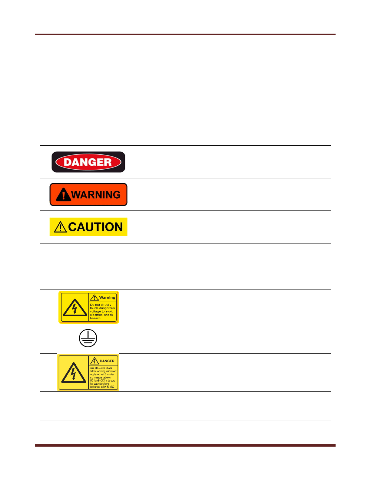
1.2. Safety and Warning Symbols
The following advisory symbols as shown in Table 1.1 will be used in the manual for different
level of warning. The meanings of the advisory symbols are explained below.
Table 1.1 Safety and warning symbols (1)
This danger symbol advises that improper operation will
cause serious personal injury or death.
This warning symbol advises that improper operation will
cause serious personal injury, or catastrophic damage the
generator or any electronic devices connected to the
generator, or lose important data.
This caution symbol advises that improper operation will
cause personal injury, damage the power supply or any
electronic devices connected to the power supply, lose data.
The following advisory symbols as shown in Table 1.2 are used on safety warning labels, and/or
on printed circuit board (only provided with white paint), and/or other part of the generator. The
meanings of these symbols are explained as below.
Table 1.2 Safety and warning symbols (2)
Dangerous voltage symbol indicates the presence of high
voltage. Access the high voltage will cause serious personal
injury or death.
To protect against electrical shock in case of a fault. This
symbol indicates that the terminal must be connected to
ground before operation of equipment.
Residual voltage:
Wait 8 minutes at least for capacitor discharge after power
cord is removed and before servicing.
Heavy object:
Two persons lifting are recommended to avoid muscle strain
or back injuries.
Page 6

Delta Electronics. Inc. HPH- 20KA01KAT
2
1.3. Electromagnetic Compatibility Directives and Standard
Disturbance Characteristic: EN55011 - CRSP11 Class A, Group 1 (>20 kVA)
General Immunity Standard for Industry: EN 61000-6-2
Safety Requirement: IEC-61010-1 (CE and UL certification)
1.4. Industry Guideline
Guideline for Semiconductor manufacturing equipment: SEMI S2 and F47
Page 7

Delta Electronics. Inc. HPH- 20KA01KAT
3
Chapter 2: Introduction
2.1. Brief Statement
Delta “HPH-20KA01KAT” is a high voltage DC generator that meets the exciting requirement in
sputtering system. Tight regulation, small output ripple and superior arc quenching make it very
suitable to be applied in most of plasma-based sputtering application.
Figure 2.1 Delta “HPH-20KA01KAT” power supply
2.2. Key Feature
Excellent Accuracy, Load Regulation, and Stability
Ultrafast Arc Suppression Detect Time
Very Low Arc Energy (< 1 mJ per kW)
Adjustable Ramp and Delay Time
Convenience for Multi-parallel Application
Remote Control Signals, User Port Analog I/O (D-sub), Host Port Digital I/O (RS-
232 and RS-485)
Page 8
Delta Electronics. Inc. HPH- 20KA01KAT
4
Chapter 3: Specification
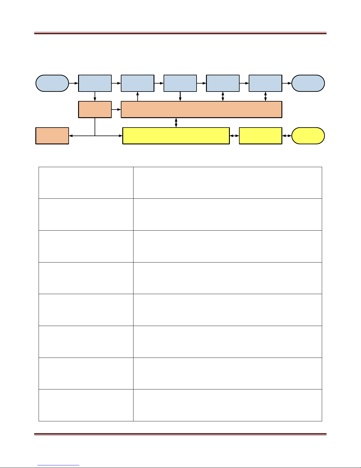
3.1. System Block Diagram
Figure 3.1 System block diagram of Delta “HPH-20KA01KAT”
Table 3.1 Detail description for block diagram
Soft Start and PFC Section
AC line voltage is applied through the circuit breaker. The contactor,
when closed, delivers the line voltage to a rectifier bridge, where it is
converted to DC bus.
Converter Section
The converter section converts DC voltage stored in the bulk
capacitors to high-frequency voltage by alternating the current
through switching power components.
Output Section
In the output section, an isolation transformer steps up the highfrequency voltage from the converter section and delivers it to a fullwave rectifier bridge. The rectified DC power is then passed through
a measurement section to the output connector.
Output Measurement and
Feedback
The output measurement section measures current and voltage, and
feedback the voltage and current information to MCU for voltage,
current and power control and related protection.
Auxiliary Power
The AUX power provides low voltage source to supply the Vcc of
analog OPA, main controller, MCU, fan and LCD display.
MCU.FPGA
The MCU is responsible for controlling the power supply status and
providing status information to the operator through all interfaces.
The FPGA dominates the arc suppression mechanism.
Control Panel Display
Control panel shows operating mode, command level, feedback
values, set up Arc processing, process control, interface setup,
communication set and system status during power supply working.
Remote Control Interface
The power supply supports three types of interfaces: a User port
(analog), a Host port (RS-232, RS-485) and an active front panel. All
three interfaces communicate operator-supplied inputs to MCU and
provide the operator with status information.
EMI Filter
Three-phase
Power Input
PFC DC Bus
DC-DC
Converter
Arc Suppressor
Soft Start
Mechanism
Wide Range
Power Output
System Controller Interface
Sensor & Driver
Auxiliary
Power
Adaptable Fan Isolation
Page 9

Delta Electronics. Inc. HPH- 20KA01KAT
5
3.2. Electrical Specification
Table 3.2 Electrical specification
Item
Specification
Condition
Input Voltage
208 V
AC
± 10% (Three Phase)
50 / 60 Hz
Input Current (Per Phase)
< 80 A
RMS
208V
AC
Input voltage
Maximum Output Power
20 kW
-
Output Voltage Range
0 to 1000 V
Output accuracy specification
guaranteed from 131 to 1000 V
Output Current Range
0 to 50 A
Output accuracy specification
guaranteed from 5 to 50 A
Power Supply Efficiency
> 90%
Rated output power at 1000 V
Power Factor
> 0.9
Rated output power
Output Voltage Ripple
< 2% (V
RM
S), line frequency
20% to 100% output power
within operation range
Output Voltage Accuracy
1% of command setting or 0.5%
of full scale voltage between
output and command
Within operation range at 25 ˚C
Output Current Accuracy
1% of command setting or 0.5%
of full scale current between
output and command
Within operation range at 25 ˚C
Output Voltage Reader (Digital
Interface) Accuracy
1% of command setting or 0.5%
of full scale voltage between
output and command
Within operation range at 25 ˚C
Output Current Reader
(Digital Interface) Accuracy
1% of command setting or 0.5%
of full scale current between
output and command
Within operation range at 25 ˚C
D-sub Reader/Command
(Analog Interface) Accuracy
1% of full scale rating P/I/V
between output and D-sub
Within operation range at 25 ˚C
Parallel Reader (Digital
Interface) Accuracy
20% of full scale rating P/I/V
between output and D-sub
Within operation range at 25˚C
Parallel D-sub Reader (Analog
Interface) Accuracy
20% of full scale rating P/I/V
between output and D-sub
Within operation range at 25˚C
Load Regulation
1% of command setting or 0.5%
of full scale voltage between
output and command
10% to 100% Output Power
Page 10
Delta Electronics. Inc. HPH- 20KA01KAT
6
Temperature Coefficient
< 50 ppm/˚C
20 to 40 ˚C
Variation in regulated output
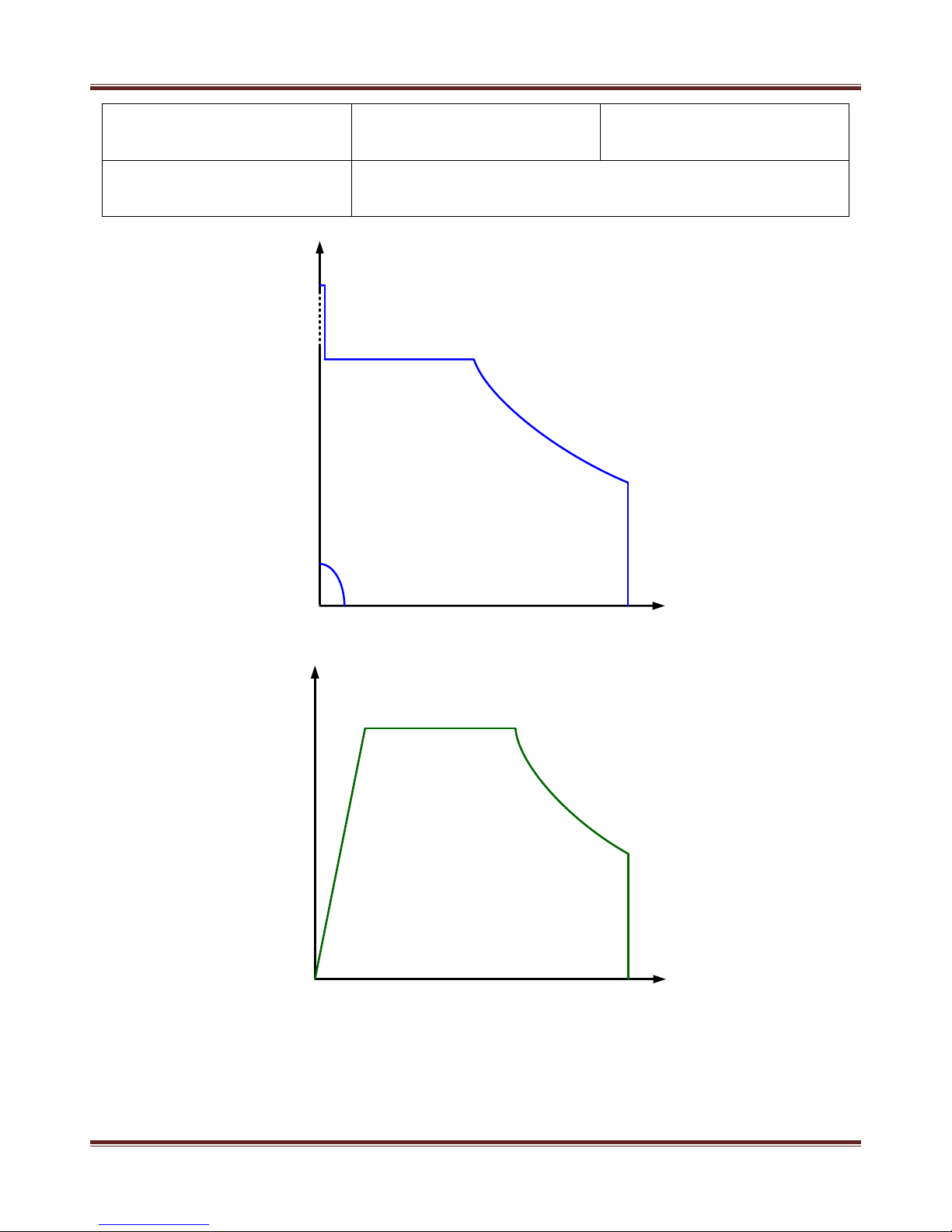
Regulation Mode
Constant voltage, current, and power mode
Figure 3.2 Operation curve of output V-I characteristic
Figure 3.3 Operation curve of output impedance characteristic
1000V
200V
400V
50A
600V
5A 20A
Power Limit
Current Limit
Voltage Limit
1900V
Operation Range
V
out
I
out
131V
20kW
10kW
8Ω
Power Limit
Current Limit
Operation Range
Z
out
50Ω 100Ω
P
out
Voltage Limit
Page 11

Delta Electronics. Inc. HPH- 20KA01KAT
7
For Delta “HPH-20KA01KAT” power supply, the maximum output voltage and current level are
1000 V and 50 A. The output characteristic is as the figures above. If the operation point is below
400 V, the power supply can provide at most 50 A, if the operation is more than 400 V, the maximum
output current will decrease to 20 A within the output voltage reaching 1000 V.
Page 12
Delta Electronics. Inc. HPH- 20KA01KAT
8
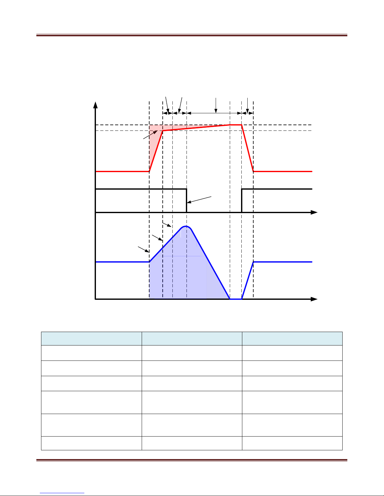
3.3. Arc Suppression Specification
Figure 3.4 shows the waveforms and key parameters under arc condition, and Table 3.3
indicates the arc energy and adjustable parameters for user.
Figure 3.4 Arc Suppression mechanisms
Table 3.3 Arc Energy specification and adjustable parameters for User
Item
Specification
Description
Delay Time
1 to 5 µs
Adjustable delay until cutoff
output after detecting arc
Pause Time
40 to 250 µs
Adjustable time between output
cutoff and recovery
Arc Trip Voltage Level
25 to 200 V
The level to determine if arc
occurs from output
Over Arc Density Protection
1 to 99
Adjustable counter to alarm if
the a frequent arc condition
occurs within 1 second
Over Arc Number Protection
1 to 999
Adjustable counter to alarm if
the arc number is over the
setting.
Arc Energy
< 1 mJ per kW
0V
0A
Arc Occurs
Detection Circuit Activated
Arc Detected
Switching off
Detection
Time
Delay
Time
Pause
Time
Arc Voltage
Trip Level
t
1
t
2
Voltage
Current
Signal of
Switching
t
t
3
t
4
t5t6t
7
Recovery
Time
Page 13

Delta Electronics. Inc. HPH- 20KA01KAT
9
Page 14

Delta Electronics. Inc. HPH- 20KA01KAT
10
3.4. Process and Monitor Function
Table 3.4 Adjustable function parameters for User
Item
Specification
Description
Max. Power
2 to 20 kW
Power will be constrained within
the value of setting prior to the
set point of regulation.
Max. Current
5 to 50 A
Current will be constrained
within the value of setting prior
to the set point of regulation.
Max. Voltage
500 to 1000 V
Voltage will be constrained
within the value of setting prior
to the set point of regulation.
Ignition Mechanism
1000 to 1900 V
A voltage up to 1900 V is
adjustable for igniting the
system.
Ramp Time
50 to 2000 ms
A ramp up to set point is
adjustable for a soft start
mechanism.
Set Point
1 to 10 s
Monitoring if the output reaches
the setting of regulation within
the setting of period.
Energy Mode
1 to 99999 kJ
Monitoring if the output energy
reaches the setting of energy.
Target Life Mode
1 to 15000 kWh
Monitoring if the output energy
reaches the setting of kWh.
3.5. Mechanical Specification
The outward appearance, cooling specification for minimum CFM Requirement, and I/O ports
of Delta “HPH-20KA01KAT” power supply are described as below:
Table 3.5 Mechanical specification
Item
Description
Physical Dimension
482.6 mm (W) x 132.5 mm (H) x 600 mm (L)
19" (W) x 5.2" (H) x 22.0" (L)
19" 3U
Weight
38.7 kg
Cooling
Fan cooling
Noise
Noise generated by this unit under 70 dB (A) at a 1m distance in 25
˚C ambient temperature
AC Input Connector
4 pin terminal block
DC Output Connector
3 pin terminal block
User Port
Analog I/O: 15-pin female D-sub
Host Port
Digital I/O: 9-pin female RS232 and RS485
Parallel Bus
8-pin RJ46
Page 15

Delta Electronics. Inc. HPH- 20KA01KAT
11
Page 16

Delta Electronics. Inc. HPH- 20KA01KAT
12
Figure 3.5 Physical dimension of HPH-20KA01KAT power supply
Cooling requirement
Minimum air flow rate: 7.36 m
3
/min (260 CFM)
Figure 3.6 Air Flow directions
Air InAir In
Air OutAir Out
Air Out Air Out
Page 17

Delta Electronics. Inc. HPH- 20KA01KAT
13
Delta “HPH-20KA01KAT” power supply is the forced air cooling type. Please keep enough
space for air flow cooling capability when it is installing to the cabinet. Air inlet on the front panel and
air outlet on the rear panel is shown in figure 3.6. Air outlet of rear panel is responsible for dissipating
the heat from inside of power supply to outside by internal two fans. The temperature of air inlet
should not exceed 40 degree C.
3.6. Environment Specification
Table 3.6 Climatic specification
Item
Temperature
Relative Humidity
Air Pressure
Operating
0 to 40 ˚C
(32 to 104 ˚F)
10% to 90% RH (Non-
condensing)
80 to 106 kPa
(approximately 2000 m
above sea level)
Storage
-25 to 55 ˚C
(-13 to 131 ˚F)
10% to 95% RH
80 to 106 kPa
(approximately 2000 m
above sea level)
Transportation
-25 to 40 ˚C
(-13 to 104 ˚F)
95% RH
(Maximum)
66 to 106 kPa
(approximately 2000 m
above sea level)
Table 3.7 Environment specification
Item
Description
Operating
Category II
Pollution Degree
Pollution Degree 2
Page 18

Delta Electronics. Inc. HPH- 20KA01KAT
14
Chapter 4: System Protection Mechanism
4.1. Input Breaker
The function of this switch is to prevent over current at input side from any malfunction
happening and simultaneously provide a manual switch for user to turn off the power supply.
4.2. Protection by MCU (A: Auto Recovery, L: Latch)
Table 4.1 Definition and description of MCU protection
Alarm Condition
Code
Description
Mode
HW Fault M1
01
Hardware error from the left module
A
HW Fault M2
02
Hardware error from the right module
A
SW OVP
03
Output over voltage
A
SW OCP
04
Output over current
A
SW OPP
06
Output over power
A
Arc Number Limit
07
Arc number is over setting parameter
L
Target Life Monitor
09
Power off while output reaches setting Energy
L
Output Interlock
11
Uninstallation of output cover
L
Contactor Interlock
12
Uninstallation of contactor pin in D-sub connector
L
Communication Loss
15
Error from internal communication
L
Fan1 Error
17
Error from the left fan
L
Fan2 Error
18
Error from the right fan
L
Bus UVP
20
Input voltage is under operation range
L
Bus OVP
21
Input voltage is over operation range
L
GND Detect
22
Positive output is not connected to system ground
L
Set Point Monitor
23
Error while output fails to reach setting parameter
within setting time
L
Energy Mode Monitor
24
Power off while output reaches setting energy
L
Parallel Fault
000
Fault from other PSU (showing on Slave)
L
Page 19

Delta Electronics. Inc. HPH- 20KA01KAT
15
Parallel Fault IP1
101
Fault from PSU IP 01 (showing on Master)
L
Parallel Fault IP2
102
Fault from PSU IP 02 (showing on Master)
L
Parallel Fault IP3
103
Fault from PSU IP 03 (showing on Master)
L
Parallel Fault IP4
104
Fault from PSU IP 04 (showing on Master)
L
Parallel Fault IP5
105
Fault from PSU IP 05 (showing on Master)
L
Parallel Fault IP6
106
Fault from PSU IP 06 (showing on Master)
L
Parallel Fault IP7
107
Fault from PSU IP 07 (showing on Master)
L
Parallel Fault IP8
108
Fault from PSU IP 08 (showing on Master)
L
Parallel Fault IP9
109
Fault from PSU IP 09 (showing on Master)
L
Parallel Fault IP10
110
Fault from PSU IP 10 (showing on Master)
L
Parallel Fault IP11
111
Fault from PSU IP 11 (showing on Master)
L
Parallel Fault IP12
112
Fault from PSU IP 12 (showing on Master)
L
Parallel Fault IP13
113
Fault from PSU IP 13 (showing on Master)
L
Parallel Fault IP14
114
Fault from PSU IP 14 (showing on Master)
L
Parallel Fault IP15
115
Fault from PSU IP 15 (showing on Master)
L
Parallel Fault IP16
116
Fault from PSU IP 16 (showing on Master)
L
Parallel Fault Master
Communication Loss
223
Master fails to receive the ack from slave while
power on
L
Parallel Fault Slave
Communication Loss
224
Slave fails to receive the ack from Master while
power on
L
Warning Condition
Code
Description
Mode
Arc Density Limit
01
Arc Density is over parameters of setting
A
Output Limit
02
Output is over setting parameters of setting
A
Parallel Number
03
Parallel number is different between setting and
reality
A
Parallel Mode
Communication Fault
04 A
Target Life
05
While output reaches setting Target Life
A
Page 20

Delta Electronics. Inc. HPH- 20KA01KAT
16
Energy Mode Monitor
06
While output reaches setting Energy
A
Page 21

Delta Electronics. Inc. HPH- 20KA01KAT
17
Chapter 5: Installation
Delta “HPH-20KA01KAT” power supply is a high voltage power supply. Please read this manual
carefully and follow the instruction before installation and operation, otherwise an electric shock or
a fatal accident might be caused.
Figure 5.1 Installation diagram
This power supply could only be placed horizontally and connect the protective grounding
to prevent an electric shock before use.
Consideration must be taken not to impede the supply or flow of air to the unit.
Please switch off the power supply before touching the case.
Before applying power, please verify that the product is set to match with the line voltage.
The circumstance temperature should be managed under 40˚C
The installation and operation should be only in pollution degree 2 or better environment.
Do not operate this device in a dusty area or in corrosive gas environment.
Proper grounding: For safe use, must connect ground cable (Yellow / Green wire) from
ground stud on the power supply rear panel to the pure earth ground. Poor grounding may
cause an electric shock or fatal accident.
Output connector must be connected with the attached output cable. (3KV/6AWG/200°C,
with shielding). Do not use other output cables.
Before applying power, please verify that the product is set to match with the line voltage.
When emergency, cut-off the circuit breaker, and then removing mains supply cord.
Operating personnel must not remove the cover of the instrument. Component replacement
and internal adjustment can be done only by qualified service personnel.
Remove mains cord and output cable before exterior maintenance and service.
Use the carrying handle when dismantling it. Avoid drop resulting in hurt.
Page 22

Delta Electronics. Inc. HPH- 20KA01KAT
18
Page 23

Delta Electronics. Inc. HPH- 20KA01KAT
19
5.1. Cooling Requirements
For the HPH-20KA01KAT A supply to be sufficiently cooled, the cabinet must be set up to:.
1. Bring in coolant air of the correct temperature(40 ˚C maximum)
2. Distribute coolant air to the power supplies
3. Prevent air exhausted from the cabinet from circulating back and becoming input air
4. Exhaust the hot air from the cabinet with minimal airflow restriction.
5.2. Cabinet Design
The following is a synopsis of the HPH-20KA01KAT A to follow when designing a cabinet
containing a stack of HPH-20KA01KAT A power supplies.
Coolant air must be drawn easily into the cabinet; exhaust air must be able to pass
unrestricted out of the cabinet. If some physical constriant restricts the flow of exhaust air out of
the cabinet, we recommend that fans or blowers be mounted so that the hot air is removed from
the cabinet as quickly as possible.
Each HPH-20KA01KAT A power supply dissipates up to 10% of its maximum power at full
rated output. The minimum air flows in cubic feet per minute(CFM) required by individual HPH20KA01KAT A supplies are shown in table 5.1. The static pressure(inches of water) of the empty
cabinet should not exceed 0.1 inches of water at the CFM level obtained by adding together the
minimum CFM values for all the power supplies that will be placed in the cabinet. For example, if
three HPH-20KA01KAT A supplies are mounted in a cabinet, the minimum CFM requirement
would be three times the CFM of cabinet air volume compared to an individual supply.
Approximations of this figure, the total power dissipation, and the temperature difference between
coolant air and exhaust air are shown as an example in table 5.2.
Table 5.1 Minimum CFM requirement for HPH-20KA01KAT unit
Type of PSU
CFM Required
20KW
260 CFM (122.7 liters/second)
Table 5.2 Approximate cooling requirements for three units mounted in a cabinet
Type of PSU
CFM for 3 Supplies
Total Power Dissipation
Dif. In Temp. Between
Coolant & Exhaust Air
20 KW x 3
780 CFM
(260+260+260=780)
(368.1 liters/second)
9000 W
(3000+3000+3000=9000)
23 ˚C
5.3. Grounding
For your convenience, the rear panel of the HPH-20KA01KAT supply features three
equipotential ground screw: three M6 screw. These are indicated on the rear panel by a ground
symbol.See figure 6.2 for more information.
Page 24

Delta Electronics. Inc. HPH- 20KA01KAT
20
5.4. Connecting For Master/Slave
The HPH-20KA01KAT A design lets you configure up to sixteen HPH-20KA01KAT as a
master/slave system (the maximum power capability depends on the master unit’s configuration
file). Any HPH-20KA01KAT A unit that features the master/slave Host card can function as either a
master unit or a slave unit. HPH-20KA01KAT units without the master/slave card cannot function
as a master or slave.
The master/slave card is located near the top right side of the unit’s rear panel. It includes
three ports:
1. A 9-pin, female, subminiature-D serial communications port for RS-485.
2. Two modular ports “Master” and “Slave” for interfacing master and slave units in a daisy
chain (see figure 5.3).
5.5. Configuring Your Master Unit
To configure the master unit, do the following steps (see Figure 5-3):
1. Remove all input power from the master and slave units.
2. Connect the interface cable between “Master” port on the master unit and “Slave”
port on the first slave unit.
3. Your master unit will not have an interface cable connected to “Slave” port.
4. Use a grounding strap to connect an equi-potential ground stud on the master unit to
an equi-potential ground stud on the first slave unit.
Note:We recommend you use a ground wire that can conduct the current of one
phase( for example, 40A for HPH-20KA01KAT) that is no longer than 3 feet. We
recommend you connect the ground stud on the master unit to system ground. See
Figure 5.2 for more information.
5. Set the front panel => Interface Setup => Prallel Mode Setup => Master
If you want to configure your master unit as a stand-alone unit, do the following steps:
1. Set the front panel => Interface Setup => Prallel Mode Setup => Master
2. Remove all Master/Slave interface cables from “Master” unit.
5.6. Configuring Your Slave Units
To configure a slave unit, do the following (see Figure 5.3)
1. Remove all input power from the master and slave units.
2. Connect the interface cable between “Master” port on the first slave unit and “Slave”
port on the next slave unit. Continue cabling slave units together in this daisy-chain
manner.
Note:The master/slave interface cables are include with the units. The last slave unit
on your system will not have an interface cable connected to “Master”port.
3. Use a grounding strap to connect an equi-potential ground stud on the first slave unit
to an equi-potential ground stud of the next slave unit.
Page 25

Delta Electronics. Inc. HPH- 20KA01KAT
21
Note:We recommend you use a ground wire that can conduct the current of one
phase( for example, 40A for HPH-20KA01KAT) that is no longer than 3 feet. We
recommend you connect the ground stud on the master unit to system ground. See
Figure 5.3 for more information.
4. Continue connecting togeter subsequent slave unit chassis as done in the previous
step.
5. Set the front panel => Interface Setup => Prallel Mode Setup => Slave
Figure 5.3 Configuration for HPH-20KA01KAT A master/slave system
5.7. Monitoring Your Master/Slave System
Page 26

Delta Electronics. Inc. HPH- 20KA01KAT
22
Following is information on monitoring the master/slave system depending on your monitoring
device:
1. If you have a passive front panel attached to your master unit, you can view the
combined output of your master/slave system (power or current). The passive front
panel of each slave unit displays the individual unit’s output.
2. If you have a host computer connected to a serial port on your master unit, you can
monitor the output (power, current or voltage) of your system and the output of each
individual unit.
3. If you want more than two in parallel, you can’t set more than one master unit at the
same time.
5.8. Clearing Faults in a Master/Slave System
If a slave unit experiences an a self-clearing fault, both the master and slave units display an
error code and the master unit shuts off output from all power supplies. When the fault condition
clears, the master and slave units reset. You may then turn on output.
Page 27

Delta Electronics. Inc. HPH- 20KA01KAT
23
Chapter 6: Interface
6.1. Front Panel
The functions for several buttons on the front panel are described on Table 6.1
Table 6.1 Function description of front panel
“Enter” Button
1. Press the button to change all of adaptive parameters.
2. Press the button to enter the next layer while in menu screen.
“Menu” Button
1. Press the button to menu screen from home screen.
2. Press the button to return to the previous layer while in menu screen.
“P” Button
Press the button to set the output condition in constant power mode. In
constant power mode user could adjust output power regulation level by
“enter button” and “knob”.
“I” Button
Press the button to set the output condition in constant current mode. In
constant current mode user could adjust output current regulation level by
“enter button” and “knob”.
“V” Button
Press the button to set the output condition in constant voltage mode. In
constant voltage mode user could adjust output voltage regulation level by
“enter button” and “knob”.
“ON” Button
Press the button to turn on the output power. While power on, user could
adjust output regulation level by “enter button” and “knob”.
“OFF” Button
Press the button to turn on the output power.
“LOCK” Button
Press the button to lock “Enter”, “Menu”, “P”, “I”, “V”, “ON”, “OFF” button.
This function could prevent any unexpected change from panel while PSU
in operation.
Regulation Knob
Rotate the knob to adjust the regulation level.
LCD Display
The display shows command of output regulation level according to control
modes of Power/Current/Voltage. It also indicates feedback values of
Power/Current/Voltage and system status, such as error conditions for all
protect signals.
Page 28

Delta Electronics. Inc. HPH- 20KA01KAT
24
Figure 6.1 Front panel
6.2. Rear Panel
1. GND terminal is for chamber grounding, and earth grounding should be performed for
safety.
2. Connect output terminal to target and connect +COM to the grounding of the chamber
Figure 6.2 Rear panel
Page 29

Delta Electronics. Inc. HPH- 20KA01KAT
25
6.3. Main Menu Map
Fig 6.1 Panel tree
Page 30

Delta Electronics. Inc. HPH- 20KA01KAT
26
Fig 6.2 Definition of LCM display
6.4. Digital Communication Port (Host)
The 9-pin female RS232/485 connector labeled “Host Port” on the rear of the power supply lets
user connect with computer to control the power supply. Definition of RS232/485 connector is as
follows:
Figure 6.3 Connector of host port, 9 pin female RS232/RS485
Table6.2 Definition of RS232/485 connector
RS232 Pin
Definition
Description
RS485 Pin
Definition
Description
1 - 1
D+
2
Tx
2
D-
3
Rx
3
-
4 - 4 - 5
GND
5 - 6 - 6
-
7 - 7
-
8 - 8 - 9 - 9
-
REG : 2 0 . 0 k W OU T : ON
1 0 0 0 V 5 0 . 0 A 2 0 . 0 k W
D : 9 9
M L T : 0 : 0 0 : 0 0S E 0 0
A
R
Command Power On/Off
Voltage/Current/Power Reader
Arc Number、Arc Density
Set Point、Energy、Target Life Mode
Run Time Hr/Min/SecMaster/Slave
9 99AN :
Lock
0>
Page 31

Delta Electronics. Inc. HPH- 20KA01KAT
27
Table 6.3 Protocol of RS232/485 definition (1)
Remote to PSU
Byte
0 1 2 3 4 5 6 7 8 9 10
IP
Command
Data1
Data2
Check Sum
Termination
Byte
H-Byte
L-Byte
H-Byte
L-Byte
H-Byte
L-Byte
0x00
Byte
0x00
0x0D
CV Mode
IP
0x11
0x00/01/02
0x00
0x00
Value
0x00
Value
0x00
0x0D
CC Mode
IP
0x12
0x00/01/02
0x00
0x00
Value
0x00
Value
0x00
0x0D
CP Mode
IP
0x13
0x00/01/02
0x00
0x00
Value
0x00
Value
0x00
0x0D
Master/Slave
IP
0x14
0x00/01
0x00
0x00
Value
0x00
Value
0x00
0x0D
A/Ri Offset
IP
0x15
0x00/01
0x00
0x00
00/01
Value
0x00
Value
0x00
0x0D
A/Vo Offset
IP
0x16
0x00/01
0x00
0x00
00/01
Value
0x00
Value
0x00
0x0D
A/Io Offset
IP
0x17
0x00/01
0x00
0x00
00/01
Value
0x00
Value
0x00
0x0D
Terminating
Resistor
IP
0x18
0x00/01
0x00
0x00
IP
Value
0x00
Value
0x00
0x0D
Set Point
IP
0x1A
0x00/01/02
Value
Value
0x00
Value
0x00
0x0D
Pause Time
IP
0x1B
0x00/01
Value
Value
0x00
Value
0x00
0x0D
Energy Mode
IP
0x1D
0x00/01/02
Value
Value
0x00
Value
0x00
0x0D
Arc Function
IP
0x1E
0x00/01
Value
Value
0x00
Value
0x00
0x0D
Parallel Number
IP
0x21
0x00/01/02
Value
Value
0x00
Value
0x00
0x0D
Max Power
IP
0x22
0x00/01
Value
Value
0x00
Value
0x00
0x0D
Max Current
IP
0x23
0x00/01
Value
Value
0x00
Value
0x00
0x0D
Max Voltage
IP
0x24
0x00/01
Value
Value
0x00
Value
0x00
0x0D
Ramp Time
IP
0x25
0x00/01
Value
Value
0x00
Value
0x00
0x0D
Target Life
IP
0x26
0x00/01/02
Value
Value
0x00
Value
0x00
0x0D
Delay time
IP
0x28
0x00/01
Value
Value
0x00
Value
0x00
0x0D
Arc Voltage
IP
0x30
0x00/01
Value
Value
0x00
Value
0x00
0x0D
Arc Density
IP
0x31
0x00/01/02
Value
Value
0x00
Value
0x00
0x0D
Arc Number
IP
0x32
0x00/01/02
Value
Value
0x00
Value
0x00
0x0D
Ignition
IP
0x33
0x00/01
Value
Value
0x00
Value
0x00
0x0D
Power On
IP
0x41
0x00/01/02
0x00
0x00
0x00
0x00
0x00
Value
0x00
0x0D
Power Off
IP
0x42
0x00/01/02
0x00
0x00
0x00
0x00
0x00
Value
0x00
0x0D
Default 1
IP
0x60
0x00
0x00
0x00
0x00
0x00
0x00
Value
0x00
0x0D
Default 2
IP
0x61
0x00
0x00
0x00
0x00
0x00
0x00
Value
0x00
0x0D
Default 3
IP
0x62
0x00
0x00
0x00
0x00
0x00
0x00
Value
0x00
0x0D
Default 4
IP
0x63
0x00
0x00
0x00
0x00
0x00
0x00
Value
0x00
0x0D
Reset
IP
0x45
0x00
0x00
0x00
0x00
0x00
0x00
Value
0x00
0x0D
Version
IP
0x70
0x02
0x00
0x00
0x00
0x00
0x00
Value
0x00
0x0D
Alarm Code/IP
IP
0x71
0x02
0x00
0x00
0x00
0x00
0x00
Value
0x00
0x0D
PSU State
IP
0x80
0x02
0x00
0x00
0x00
0x00
0x00
Value
0x00
0x0D
Note 6.1: For L-Byte of Command, 0x00 means writing command to MCU, 0x01 means reading
command from MCU, and 0x02 means reading feedback value.
Example:
CV Mode command code:
0x11 0x00 means writing command to MCU.
0x11 0x01 means reading command from MCU.
0x11 0x02 means reading voltage from feedback.
Page 32

Delta Electronics. Inc. HPH- 20KA01KAT
28
Table 6.4 Protocol of RS232 definition (2)
PSU to Remote
Byte
0 1 2 3 4 5 6 7 8 9 10
IP
Command
Data1
Data2
Check Sum
Termination
Byte
H-Byte
L-Byte
H-Byte
L-Byte
H-Byte
L-Byte
0x00
Byte
0x00
0x0D
CV Mode
IP
0x11
0x0A
0x00
0x00
Value
0x00
Value
0x00
0x0D
CC Mode
IP
0x12
0x0A
0x00
0x00
Value
0x00
Value
0x00
0x0D
CP Mode
IP
0x13
0x0A
0x00
0x00
Value
0x00
Value
0x00
0x0D
Master/Slave
IP
0x14
0x0A
0x00
0x00
Value
0x00
Value
0x00
0x0D
A/Ri Offset
IP
0x15
0x0A
0x00
0x00
00/01
Value
0x00
Value
0x00
0x0D
A/Vo Offset
IP
0x16
0x0A
0x00
0x00
00/01
Value
0x00
Value
0x00
0x0D
A/Io Offset
IP
0x17
0x0A
0x00
0x00
00/01
Value
0x00
Value
0x00
0x0D
Terminating
Resistor
IP
0x18
0x0A
0x00
0x00
IP
Value
0x00
Value
0x00
0x0D
Set Point
IP
0x1A
0x0A
Value
Value
0x00
Value
0x00
0x0D
Pause Time
IP
0x1B
0x0A
Value
Value
0x00
Value
0x00
0x0D
Energy Mode
IP
0x1D
0x0A
Value
Value
0x00
Value
0x00
0x0D
Arc Function
IP
0x1E
0x0A
Value
Value
0x00
Value
0x00
0x0D
Parallel Number
IP
0x21
0x0A
Value
Value
0x00
Value
0x00
0x0D
Max Power
IP
0x22
0x0A
Value
Value
0x00
Value
0x00
0x0D
Max Current
IP
0x23
0x0A
Value
Value
0x00
Value
0x00
0x0D
Max Voltage
IP
0x24
0x0A
Value
Value
0x00
Value
0x00
0x0D
Ramp Time
IP
0x25
0x0A
Value
Value
0x00
Value
0x00
0x0D
Target Life
IP
0x26
0x0A
Value
Value
0x00
Value
0x00
0x0D
Delay time
IP
0x28
0x0A
Value
Value
0x00
Value
0x00
0x0D
Arc Voltage
IP
0x30
0x0A
Value
Value
0x00
Value
0x00
0x0D
Arc Density
IP
0x31
0x0A
Value
Value
0x00
Value
0x00
0x0D
Arc Number
IP
0x32
0x0A
Value
Value
0x00
Value
0x00
0x0D
Ignition
IP
0x33
0x0A
Value
Value
0x00
Value
0x00
0x0D
Power On
IP
0x41
0x0A
0x00
0x00
Value
0x00
Value
0x00
0x0D
Power Off
IP
0x42
0x0A
0x00
0x00
Value
0x00
Value
0x00
0x0D
Default 1
IP
0x60
0x0A
0x00
0x00
0x00
0x00
Value
0x00
0x0D
Default 2
IP
0x61
0x0A
0x00
0x00
0x00
0x00
Value
0x00
0x0D
Default 3
IP
0x62
0x0A
0x00
0x00
0x00
0x00
Value
0x00
0x0D
Default 4
IP
0x63
0x0A
0x00
0x00
0x00
0x00
Value
0x00
0x0D
Reset
IP
0x45
0x0A
0x00
0x00
Value
0x00
Value
0x00
0x0D
Version
IP
0x70
0x0A
0x00
0x00
Value
0x00
Value
0x00
0x0D
Alarm Code/IP
IP
0x71
0x0A
0x00
0x00
Value
0x00
Value
0x00
0x0D
Byte
0 1 2 3 4 5 6 7 8 9 10
11
IP
Command
Status1
Status2
Warning
Alarm
Voltage
Current
Power
PSU
State
12
13
14
15
16
17
18
19
20
21
22
23
Reg
Arc Density
Arc Number
Check Sum
Termination
Status L-
byte
0 1 2 3 4 5 6
7
Standby
OVP
OCP
OTP
OPP
Interlock
Arc
Protection
Output
Limit
Status H-
byte
0 1 2 3 4 5 6
7
CV Mode
CC Mode
CP Mode
Power On
Remote
Ignition
Warning
Shutdown
Page 33

Delta Electronics. Inc. HPH- 20KA01KAT
29
Note 6.2: Check Sum value is the summation of “1” signal calculated by byte 0 to 7.
Example:
“Master IP is 01, Power On”, Byte 0~7 are “0x01-0x41-0x00-0x00-0x00-0x00-0x00-0x00”.
There are three “1” in this command, so checksum is 3.
Note 6.3: Use 9600bps, 8 data bits, no parity, 1 stop bit (9600/8-N-1).
Note 6.4: PSU state Byte 4(Warning) and Byte 5(Alarm) value refer to table 4.1
Table 6.5 Value definition (Translate decimal to hexadecimal for utilizing)
Command
Byte3
Byte4
Byte5
Byte6
CV Mode
0 to 1000 for 0 to 1000V
CC Mode
0 to 500 for 0~50.0A
CP Mode
0 to 200 for 0 to 20.0kW
Master/Slave
Master: 00, Slave: 01
A/Ri Offset
Plus: 00, Minus: 01
0 to 99 for 0 to 9.9%
A/Vo Offset
Plus: 00, Minus: 01
0 to 99 for 0 to 9.9%
A/Io Offset
Plus: 00, Minus: 01
0 to 99 for 0 to 9.9%
Terminating Resistor
IP for 1 to 16
OFF: 0, On: 1
Set Point
1 to 10 for 1 to 10s
Pause Time
4 to 25 for 40 to 250us, Scale: 10us
Energy Mode
1 to 99999 for 1 to 99999kJ, 0: OFF
Arc Function
OFF: 0, ON: 1
Parallel Number
1 to 16 for 1 to 16 sets
Max Power
20 to 200 for 2 to 20kW
Max Current
50 to 500 for 5 to 50A
Max Voltage
500 to 1000 for 500 to 1000V
Ramp Time
5 to 200 for 50 to 2000ms
Target Life
0 to 1500000 for OFF to 15000.00kWh, 0: OFF
Delay time
0 to 5 for 0 to 5us
Arc Voltage
25 to 200 for 25 to 200V
Arc Density
0 to 99 for 0 to 99 times/s
Arc Number
0 to 999 for 0 to 999 times
Ignition
10 to 19 for 1000 to 1900V
Page 34

Delta Electronics. Inc. HPH- 20KA01KAT
30
6.5. Analog Communication Port (User)
The 15-pin female subminiature-D connector labeled “User Port” on the rear of the power supply
lets you connect with control box to control the power supply in analog signal. Definition of 15-pin
female subminiature-D connector is as follows:
Figure 6.4 Connector of user port, 15pin female subminiature-D
Table 6.6 Definition of subminiature-D connector
Pin Define
I/O
Description
1
+24V
I
External 24V is connected to the collector of photo
coupler
2
VOUT_A
O
Pin 2 shows the reader of output voltage
0 to 10 V for V = 0 to 1000 V
3
POUT_A
O
Pin 3 shows the reader of output Power
0 to 10 V for P = 0 to 20 kW
4
OUTPUT_ENABLE_D
I
Turn on the output power by pulling the pin low
5
XPROG_A
I
User could adjust regulation by Pin 5
0 to 10 V for P = 0 to 20 kW
6
COM_A
-
The return pin for VOUT_A, POUT_A, XPROG_A
7
PWRON_D
O
Pin 7 shows the on/off state of output
8
PWRON COM_D
-
The return pin for PWRON_D
9
OUTPUT_ENABLE_COM_D
-
The return pin for OUTPUT_ENABLE_D
PSU
Digital Signal Output
Digital Signal Input
Vcc
Vcc
+15V_ISO
Analog Signal Input
Vcc
+15V_ISO
Analog Signal Output
15-pin D-sub
+15V_ISO
Page 35

Delta Electronics. Inc. HPH- 20KA01KAT
31
10
MOD GREEN
O
Pin 10 is connected to the emitter of photo coupler
for MOD GREEN function
11
INTERLOCK_D
I
Pin 11 indicates the disconnection of interlock
12
INTLK COM_D
-
The return pin for INTERLOCK_D
13
NET GREEN
O
Pin 13 is connected to the emitter of photo coupler
for NET GREEN function
14
MOD AMBER
O
Pin 14 is connected to the emitter of photo coupler
for MOD AMBER function
15
NET AMBER
O
Pin 15 is connected to the emitter of photo coupler
for NET AMBER function
Note 6.5: Precaution for external connection
Port of Digital Signal Input
To control the input signal, a switch is utilized between the ports and isolated ground.
Open → Floating
Close → Grounding
Port of digital Signal output
The internal resistance of the ports is 5.1 kohm, and a pull-up power supply V
pull-up
is
required with a 5.1 kohm resistor.
Initial → > 0.9 * V
pull-up
Trigger → < 0.5 * V
pull-up
+ 1 V
If V
pull-up
is connected to “+15V_ISO” supplied by pin18 with a 5.1 kohm resistor, initial state
would be high than 13.5 V and trigger state would be lower than 8.5 V.
Analog Signal Input Port
An isolated amplifier is utilized in the ports. The voltage level is 0 to 10 V for user to enter
the command and shall not greater than 12 V.
Analog Signal output Port
An isolated amplifier is utilized in the ports. The voltage level is 0 to 10 V for users to read
out the output values of voltage, current, and power.
Page 36

Delta Electronics. Inc. HPH- 20KA01KAT
32
Chapter 7: Operation
7.1. Local Operating Steps
Step A
Import AC voltage to input connector on rear panel. The mains voltage level should be 400±
10% V
AC
.
Step B
Turn on the breaker to start the power supply. Now, you can see “LCD Display” is working and
shows the default setting of the power supply.
Step C
Choose one operating mode from “P”, “I”, “V” button, and “LCD Display” will show the mode you
selected and change the command unit mode by mode.
Operating mode cannot be changed during power on period. It only can select while power off.
Step D
Rotate the knob to adjust the regulation level. The command (P, I or V) will change by different
mode selection in step B. When in Power mode, the command can be adjusted from 0 to 20 kW;
when in Current mode, command can be adjusted from 0 to 50 A; when in Voltage mode, and
command can be adjusted from 130 to 1000 V
Step E
Press the “On” button to turn on the output power. While power on, user could adjust output
regulation level by “Enter” button and “knob”. “LCD Display” will show the feedback values once the
output is on.
After power on, the electric shock may lead to death or serious injury. Please read this manual
carefully and follow the instruction steps before installation and operation, otherwise an electric
shock or a fatal accident might be caused.
Step F
Press the “Off” button to turn off the output power.
Step G
If the power supply is kept off for a while, please remove AC power cord.
Don’t touch the load before grounding it. And make sure the electricity is fully discharged by meter.
Page 37

Delta Electronics. Inc. HPH- 20KA01KAT
33
7.2. D-sub Operating Steps
Example : CP mode 20 kW output
Operating steps:
1. Set the front panel => Interface Setup => Communnication Setup => D-sub.
2. Command Level: Set +10 V input to pin 5 for 20 kW Command.
3. Power On: Connect pin 4 to pin 9
4. Power Off: Remove pin4 from pin 9.
7.3. RS-232 Operating Steps
1. Set the front panel => Interface Setup => Communnication Setup => RS-232.
2. Follow the protocol defined in chapter 6.4 to operating.
7.4. RS-485 Operating Steps
1. Set the front panel => Interface Setup => Communnication Setup => RS-485.
2. Follow the protocol defined in chapter 6.4 to operating.
7.5. Parallel Operating Steps
Parallel operating example 1: Two sample parallel
Operating steps:
1. Connecting set up follow chapter 5
2. Panel System Configuration Parallel Number 2
3. Parallel port 5~8 set IP position, two sample must set up different IP
Example: sample 1 set 0000, sample 2 set 0001
4. Than can follow chapter 7.1 turn on output
Parallel operating example 2: Three sample parallel
Operating steps:
1. Connecting set up follow chapter 5
2. Panel System Configuration Parallel Number 3
3. Parallel port 5~8 set IP position, two sample must set up different IP
Example: sample 1 set 0000, sample 2 set 0001,sample 3 set 0010
4. Than can follow chapter 7.1 turn on output
Page 38

Delta Electronics. Inc. HPH- 20KA01KAT
34
Chapter 8: Maintenance
Alarm Condition
Code
Description
Suggested Action
HW Fault M1
01
Hardware error from the left module
Take all safety precaution, and
then check if the mains voltage
that is in specification. Turn on
the output power with a dummy
load to ensure if it is under
normal operation.
HW Fault M2
02
Hardware error from the right
module
Take all safety precaution, and
then check if the mains voltage
that is in specification. Turn on
the output power with a dummy
load to ensure if it is under
normal operation.
SW OVP
03
Output over voltage
Take all safety precaution, and
then check if the mains voltage
that is in specification. Turn on
the output power with a dummy
load to ensure if it is under
normal operation.
SW OCP
04
Output over current
Take all safety precaution, and
then check if the mains voltage
that is in specification. Turn on
the output power with a dummy
load to ensure if it is under
normal operation
SW OPP
06
Output over power
Take all safety precaution, and
then check if the mains voltage
that is in specification. Turn on
the output power with a dummy
load to ensure if it is under
normal operation.
Arc Number Limit
07
Arc number is over setting
parameter
Press and hold “OFF” button
with 10 second to clear error.
Contactor Interlock
10
Uninstallation of contactor pin in D-
sub connector
Check if contactor pin in D-sub
connector is short.
Output Interlock
11
Uninstallation of output cover
Check if output cover is
correctly installed.
Communication Loss
15
Error from internal communication
Check if the bus between panel
and control card is correctly
connected.
Fan1 Error
17
Error from the left fan
Check if the cable between fan
in the left module 1 and control
card is correctly connected.
Fan2 Error
18
Error from the right fan
Check if the cable between fan
in the right module 2 and control
card is correctly connected.
Bus UVP
20
Input voltage is under operation
range
Take all safety precaution, and
then check if the mains voltage
that is in specification.
Page 39

Delta Electronics. Inc. HPH- 20KA01KAT
35
Bus OVP
21
Input voltage is over operation range
Take all safety precaution, and
then check if the mains voltage
that is in specification.
GND Detect
22
Positive output is not connected to
protective earth
Check if the output positive
terminal is short to protective
earth.
Set Point Monitor
23
Error while output fails to reach
setting parameter within setting time
Take all safety precaution, and
then turn on the output power
with a dummy load to ensure if
it is under normal operation.
Energy Mode Monitor
24
Power off while output reaches
setting Energy
Monitor Setting is end. Press
and hold “OFF” button with 10
second to clear error.
Parallel Fault IP1
101
Fault from PSU IP 01
Check the PSU with IP 01
independently to ensure the
operation is normal.
Parallel Fault IP2
102
Fault from PSU IP 02
Check the PSU with IP 02
independently to ensure the
operation is normal.
Parallel Fault IP3
103
Fault from PSU IP 03
Check the PSU with IP 03
independently to ensure the
operation is normal.
Parallel Fault IP4
104
Fault from PSU IP 04
Check the PSU with IP 04
independently to ensure the
operation is normal.
Parallel Fault IP5
105
Fault from PSU IP 05
Check the PSU with IP 05
independently to ensure the
operation is normal.
Parallel Fault IP6
106
Fault from PSU IP 06
Check the PSU with IP 06
independently to ensure the
operation is normal.
Parallel Fault IP7
107
Fault from PSU IP 07
Check the PSU with IP 07
independently to ensure the
operation is normal.
Parallel Fault IP8
108
Fault from PSU IP 08
Check the PSU with IP 08
independently to ensure the
operation is normal.
Parallel Fault IP9
109
Fault from PSU IP 09
Check the PSU with IP 09
independently to ensure the
operation is normal.
Parallel Fault IP10
110
Fault from PSU IP 10
Check the PSU with IP 10
independently to ensure the
operation is normal.
Parallel Fault IP11
111
Fault from PSU IP 11
Check the PSU with IP 11
independently to ensure the
operation is normal.
Parallel Fault IP12
112
Fault from PSU IP 12
Check the PSU with IP 12
independently to ensure the
operation is normal.
Parallel Fault IP13
113
Fault from PSU IP 13
Check the PSU with IP 13
independently to ensure the
operation is normal.
Page 40

Delta Electronics. Inc. HPH- 20KA01KAT
36
Parallel Fault IP14
114
Fault from PSU IP 14
Check the PSU with IP 14
independently to ensure the
operation is normal.
Parallel Fault IP15
115
Fault from PSU IP 15
Check the PSU with IP 15
independently to ensure the
operation is normal.
Parallel Fault IP16
116
Fault from PSU IP 16
Check the PSU with IP 16
independently to ensure the
operation is normal.
Parallel Fault Master
Communication Loss
223
Master fails to receive the ack from
slave while power on
Check the RJ46 cable is
correctly connected between
master and slave PSUs.
Parallel Fault Slave
Communication Loss
224
Slave fails to receive the ack from
Master while power on
Check the RJ46 cable is
correctly connected between
master and slave PSUs.
Warning Condition
Code
Description
Suggested Action
Arc Density Limit
01
Arc density is over setting parameter
N/A
Output Limit
02
Output is over setting parameter
N/A
Parallel Number
03
Parallel number is different between
setting and reality
Check if parallel number is
correct between setting and
system detection.
Parallel Mode
Communication Fault
04
Target Life
05
While output reaches setting Target
Life
Monitor setting is end. Re-turn
on the power. It will reset the
setting
Energy Mode Monitor
06
While output reaches setting Energy
Monitor setting is end. Re-turn
on the power. It will reset the
setting
Page 41

Delta Electronics. Inc. HPH- 20KA01KAT
37
 Loading...