

Page 1
Operating manual
Manometers for Pitot tubes /
thermometers
HD2114P.0 – HD2114P.2
HD2134P.0 – HD2134P.2
www.deltaohm.com
Companies / Brands of GHM
English
Keep for future reference.
Page 2

HD2114P/HD2134P - 2 - V2.3
CONTENTS
INTRODUCTION ..................................................................................................................................................... 3
KEYBOARD AND MENU DESCRIPTION ............................................................................................................ 8
THE PROBES ..........................................................................................................................................................14
OPERATION ............................................................................................................................................................15
DIMENSION S OF PITOT TUBES..................................................................................................................................16
FLOW RATE MEASUREMENT ....................................................................................................................................16
TEMPERATURE MEASUREMENT ...............................................................................................................................18
WARNINGS AND OPERATING INSTRUCTIONS ..............................................................................................20
INSTRUMENT SIGNALS AND FAULTS ..............................................................................................................21
LOW BATTERY WARNING AND BATTERY REPLACEMENT .......................................................................23
INSTRUMENT STORAGE .....................................................................................................................................24
SERIAL INTERFACE AND USB ...........................................................................................................................25
STORING AND TRANSFERRING DATA TO A PERSONAL COMPUTER ......................................................27
THE LOGGING FUNCTION - ONLY FOR HD2114P.2 AND HD2134P.2 .........................................................................27
CLEARING THE MEMORY - ONLY FOR HD2114P.2 AND HD2134P.2 ..........................................................................27
THE PRINT FUNCTION - ONLY FOR HD2114P.2 AND HD2134P.2 .............................................................................28
CONNECTION TO A PC ........................................................................................................................................29
CONNECTION TO THE RS232C SERIAL PORT OF THE INSTRUMENT - ONLY FOR HD2114P.2 AND HD2134P.2 ..............29
CONNECTION TO THE USB 2.0 PORT OF THE INSTRUMENT - ONLY FOR HD2114P.2 AND HD2134P.2..........................29
NOTES ABOUT WORKING AND OPERATIVE SAFETY ..................................................................................30
INSTRUMENT TECHNICAL CHARACTERISTICS ...........................................................................................31
TYPE K THERMOCOUPLE PROBES ............................................................................................................................33
ORDER CODES ......................................................................................................................................................34
Page 3

HD2114P/HD2134P - 3 - V2.3
INTRODUCTION
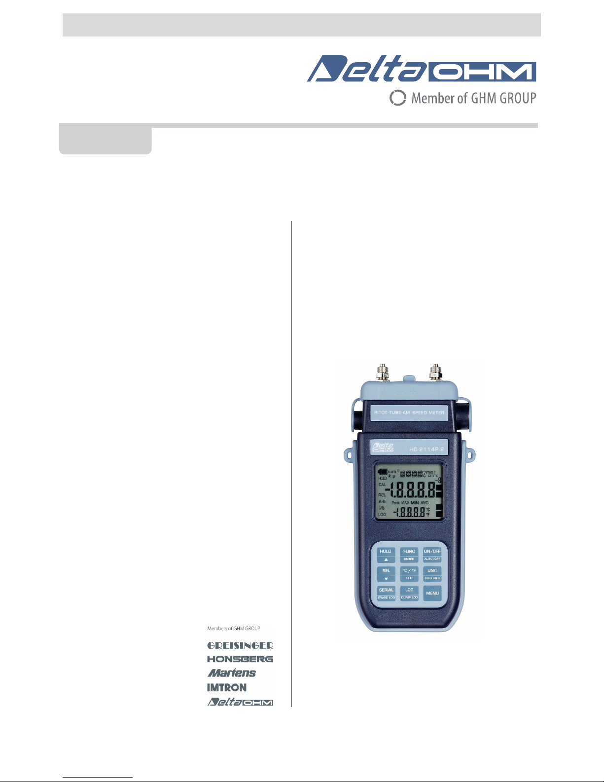
The HD2114P.0 and HD2114P.2, HD2134P.0 and HD2134P.2 are portable micromanometers
using Pitot or Darcy tubes and a large LCD display. They are used to perform measurements in the
fields of air conditioning, heating and ventilation.
They measure the differential pressure detected by a Pitot or Darcy tube connected to the instrument
inputs acquiring the wind speed and flow rate inside pipelines and vents. They also measure the
temperature using a type K thermocouple sensor.
The HD2114P.2 and HD2134P.2 instruments are dataloggers. They memorize up to 36,000
samples which can be transferred from the instrument connected to a PC via the RS232C serial port
or USB 2.0 port. The storing interval, printing, and baud rate can be configured using the menu.
The HD2114P.2 and HD2134P.2 instruments can transfer via the RS232C serial port the acquired
measurements to a PC or to a portable printer in real time.
The Max, Min and Avg function calculates the maximum, minimum or average values. Other
functions include: the relative measurement REL, the HOLD function, and the automatic turning off
which can also be disabled.
The instruments have IP66 protection degree.
If not otherwise specified, this manual's descriptions are intended to be applicable to all
models.
Page 4
HD2114P/HD2134P - 4 - V2.3
HD2114P.0 - HD2134P.0
Micromanometer with Pitot tube - Thermometer
Page 5

HD2114P/HD2134P - 5 - V2.3
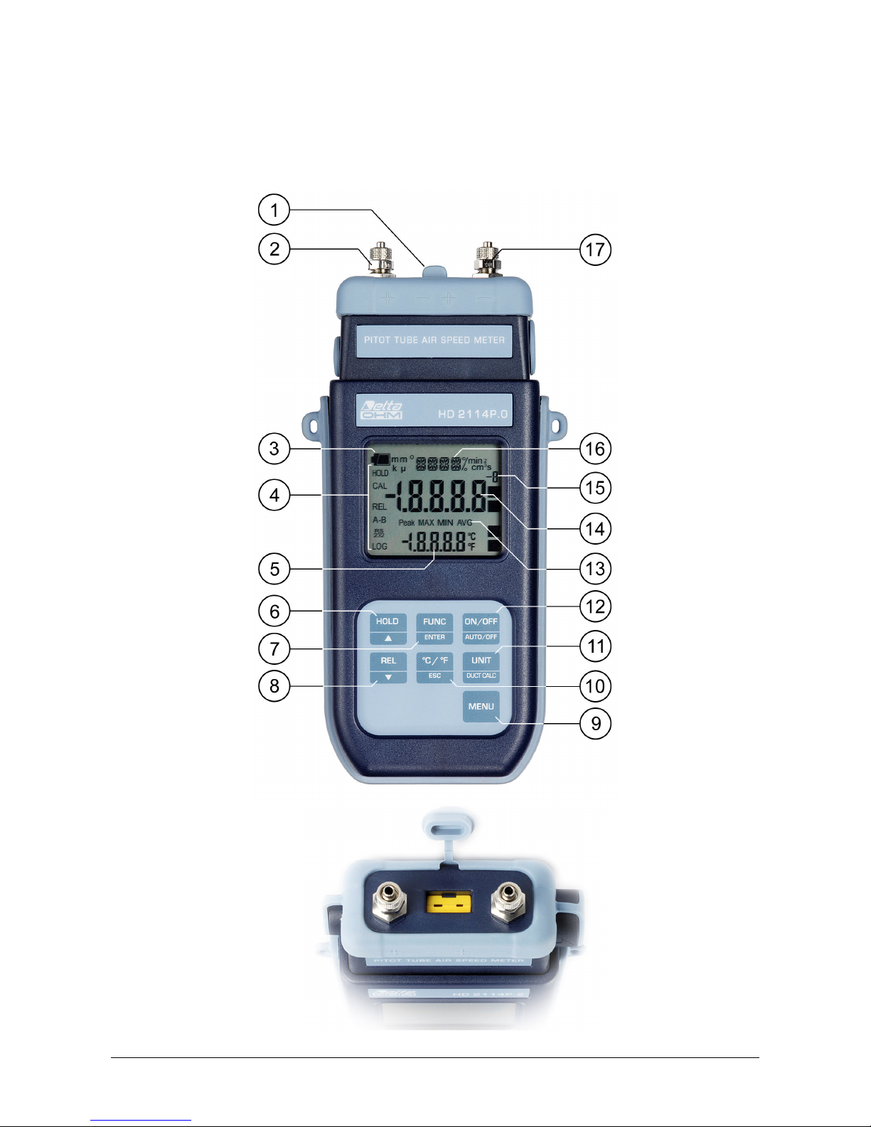
HD2114P.0 - HD2134P.0
1. Input for thermocouple K, standard miniature connector.
2. Positive input (+) into the pressure sensor. Quick coupling Ø 5mm
3. Battery symbol: displays the battery charge level.
4. Function indicators.
5. Secondary display line.
6. HOLD/ key: freezes the measurement during normal operation; in the menu, increases the
current value.
7. FUNC/ENTER key: during normal operation displays the maximum (MAX), the minimum
(MIN) and the average (AVG) of current measurements; in the menu, confirms the current
selection.
8. REL/ key: enables the relative measurement (displays the difference between the current
value and the logged value when the key is pressed); in the menu, decreases the current value.
9. MENU key: allows access to and exit from the menu.
10. °C/°F-ESC key: when the thermocouple probe is not connected, it allows manual modification
of the temperature. When double pressed, changes the unit of measurement for temperature
from degrees Celsius to Fahrenheit; in the menu, cancels the operation in progress without
making changes.
11. UNIT/DUCT CALC key: during normal operation selects the unit of measurement for the
main variable; when pressed together with the FUNC key, starts the duct flow rate calculation
procedure.
12. ON-OFF/AUTO-OFF key: turns the instrument on and off; when pressed together with the
HOLD key, disables the automatic turn off.
13. Peak, MAX, MIN and AVG symbols.
14. Main display line.
15. Degree of multiplication -3, 3 or 6: the apex, if present, indicates that the displayed
measurement must be divided by 1000 (apex "-3"), multiplied by 1000 (apex "3") or by
1,000,000 (apex "6").
16. Line for symbols and comments.
17. Negative input (-) into the pressure sensor. Quick coupling Ø 5mm
Page 6
HD2114P/HD2134P - 6 - V2.3
HD2114P.2 - HD2134P.2
Micromanometer with Pitot tube - Thermometer
Page 7

HD2114P/HD2134P - 7 - V2.3
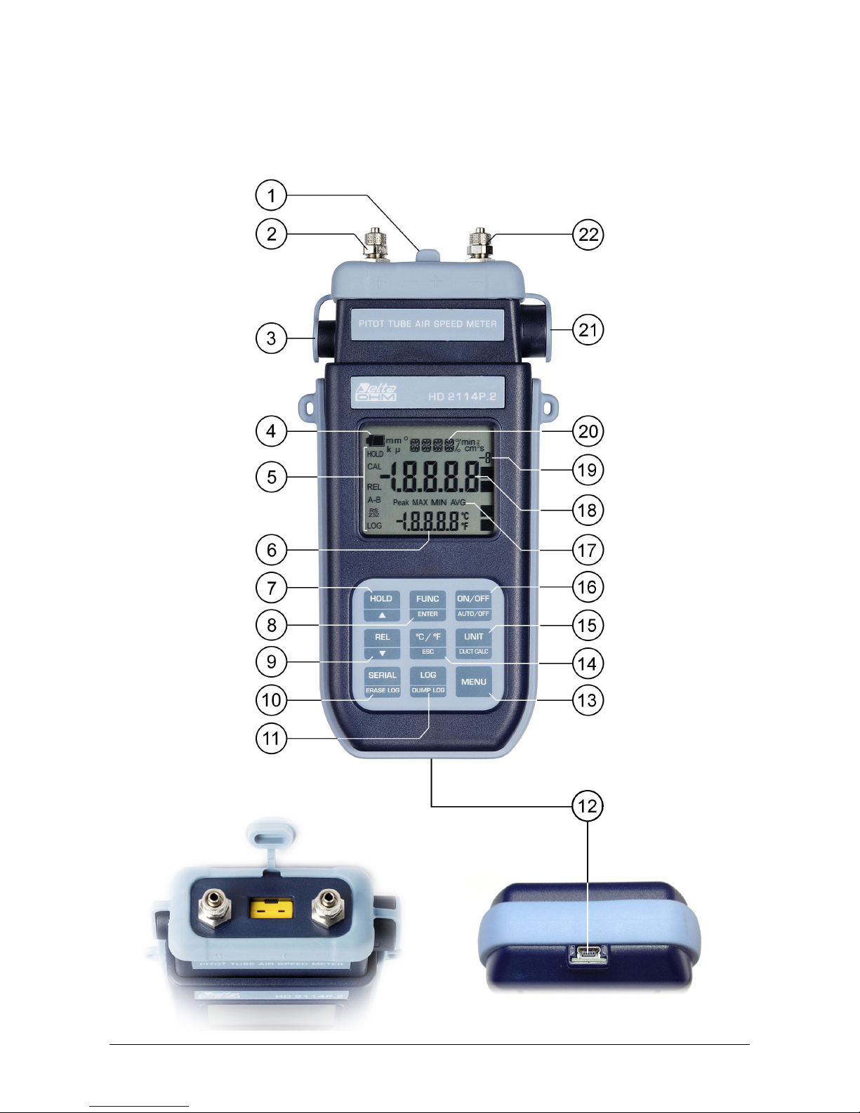
HD2114P.2 - HD2134P.2
1. Input for thermocouple K, standard miniature connector.
2. Positive input (+) into the pressure sensor. Quick coupling Ø 5mm
3. External auxiliary power supply connector input (positive at centre).
4. Battery symbol: displays the battery charge level.
5. Function indicators.
6. Secondary display line.
7. HOLD/ key: freezes the measurement during normal operation; in the menu, increases the
current value.
8. FUNC/ENTER key: during normal operation displays the maximum (MAX), the minimum
(MIN) and the average (AVG) of current measurements; in the menu, confirms the current
selection.
9. REL/ key: enables the relative measurement (displays the difference between the current
value and the logged value when the key is pressed); in the menu, decreases the current value.
10. SERIAL/ERASE LOG key: starts and ends the data transfer to the serial communication port.
In the menu, clears the data contained in the instrument's memory.
11. LOG/DUMP LOG key: during normal operation, starts and ends the saving of the data in the
internal memory; in the menu, starts the data transfer from the instrument's memory to the PC.
12. Mini-USB type B connector for USB 2.0. For the connection to PC (with cable CP23).
13. MENU key: allows access to and exit from the menu.
14. °C/°F-ESC key: when the thermocouple probe is not connected, it allows manual modification
of the temperature. When double pressed, changes the unit of measurement for temperature
from degrees Celsius to Fahrenheit; in the menu, cancels the operation in progress without
making changes.
15. UNIT/DUCT CALC key: during normal operation selects the unit of measurement for the
main variable; when pressed together with the FUNC key, starts the duct flow rate calculation
procedure.
16. ON-OFF/AUTO-OFF key: turns the instrument on and off; when pressed together with the
HOLD key, disables the automatic turn off.
17. Peak, MAX, MIN and AVG symbols.
18. Main display line.
19. Degree of multiplication -3, 3 or 6: the apex, if present, indicates that the displayed
measurement must be divided by 1000 (apex "-3"), multiplied by 1000 (apex "3") or by
1,000,000 (apex "6").
20. Line for symbols and comments.
21. 8-pole MiniDin connector for RS232C. For the connection to PC (with cable HD2110CSNM or
C206) or printer (with cable HD2110CSNM).
22. Negative input (-) into the pressure sensor. Quick coupling Ø 5mm
Page 8
HD2114P/HD2134P - 8 - V2.3
KEYBOARD AND MENU DESCRIPTION
Foreword
The instrument keyboard is composed of single-function keys, like the MENU key, and doublefunction keys such as the ON-OFF/Auto-OFF key.
In the double-keys, the function in the upper part is the "main function", while the one in the bottom
part is the "secondary function". When the instrument is in standard measurement mode, the main
function is active. In the menu or in conjunction with the FUNC key, the secondary function is
enabled.
The pressing of a key is accompanied by a short confirmation beep: a longer beep sounds if the
wrong key is pressed.
Each key specific function is described in detail below.
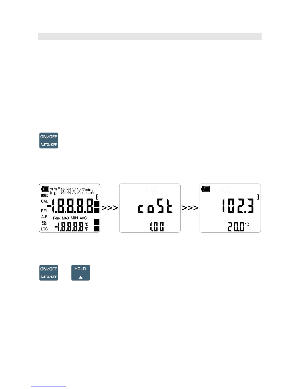
ON-OFF/AUTO-OFF key
The instrument is turned on and off using the ON/OFF key. The turning on enables all display
segments for a few seconds, displays the setting of the Pitot or Darcy tube constant (please see the
Cost_PIT_DARC parameter on page 11) and sets the instrument ready for normal measurement.
If no thermocouple probe is connected to the input, it is the manual temperature which is
displayed in the secondary line. This value is 25°C by default.
+
Automatic turning off
The instrument has an AutoPowerOff function that automatically turns the instrument off after about
8 minutes if no key is pressed during the intervening time. The AutoPowerOff function can be
disabled by holding the HOLD key pressed down when turning the instrument on: the battery
symbol will blink to remind the user that the instrument can only be turned off by pressing the
<ON/OFF> key.
The automatic turning off function for the HD2114P.2 and HD2134P.2 models is disabled
when external power is used. On the other hand, it cannot be disabled when the batteries are
discharged.
Page 9

HD2114P/HD2134P - 9 - V2.3
FUNC/ENTER key
During normal measurement this enables the display and logging of the maximum (MAX),
minimum (MIN) and average (AVG) value of the measurements captured by the Pitot tube
connected to the instrument, updating them with the acquisition of new samples. The acquisition
frequency is once a second.
The calculation is performed on the pressure, wind speed or flow rate appearing on the display upon
pressure of the FUNC key: by changing the unit of measurement, the Max, Min and Avg values are
cleared.
The MAX, MIN and AVG measurements remain in the memory until the instrument is on, even
after exiting the calculation function. To reset the previous values and restart with a new
measurement session, press FUNC until the message "FUNC CLR" appears, then use the arrows to
select YES and confirm using ENTER.
In the menu, the ENTER key confirms the current parameter and then goes to the next one. Pressed
together with the UNIT/DuctCalc key, enables the flow rate calculation (please see the UNIT key
description).
Attention: the data captured using the Record function cannot be transferred to the PC.
HOLD/ key
It increases the current parameter when used in the menu; when used in measurement mode, it
freezes the measurement in progress, and upon application of pressure on the key, the message
HOLD appears in the upper side of the display. To return to the current measurement, press the
key again.
Upon turning on the instrument, the AutoPowerOff function can be disabled by holding the HOLD
key down (please see the ON-OFF key description).
UNIT key
In measurement mode, it allows selection of the unit of measurement of the pressure, wind speed
and calculated flow rate (shown in the central line of the display). By repeatedly pressing the key,
the different units of measurement are displayed in sequence: Pa, mbar, mmH
2
O, PSI for the
differential pressure, m/s, km/h, ft/m, mph, knot for the wind speed and l/s, m3/h, cfm for the flow
rate.
This setting changes the information displayed and, for the HD2114P.2 and HD2134P.2 models the
immediate print of data (SERIAL key).
The data recorded using the LOG function (HD2114P.2 and HD2134P.2) keep the chosen unit
of measurement displayed during logging.
The unit of measurement associated with the data sent to the printer or PC through the serial
port using the SERIAL function (HD2114P.2 and HD2134P.2), must be selected before
starting the print function.
Page 10

HD2114P/HD2134P - 10 - V2.3
°C/°F - ESC key
The measured temperature value is used to compensate the wind speed measurement. When the
temperature probe is connected, the key changes the unit of measurement from degrees Celsius to
Fahrenheit.
If the probe is not present, the compensation temperature must be entered manually: to manually
change the value shown in the display lower line, press °C/°F once. The temperature indicated starts
blinking. While the display is blinking, it is possible to change the compensation temperature in the
-200…+600°C range using the arrows ( and ). Confirm using ENTER. The display stops
blinking, and that temperature is used for compensation.
If the temperature probe is not present, to change the unit of measurement between °C and °F, it is
necessary to press twice the °C/°F key.
REL/ key
In measurement mode, it displays the difference between the current value and that measured on
pressing the key for both measurements - main and secondary. The REL message appears on the
display; press the key again to return to the current measurement. The REL function is not applied
to manual temperature: if the thermocouple probe is not present, on pressing REL the error
indication ERR appears.
When used in the menu, it decreases the current variable value.
MENU Key
The first menu item is accessed by initially pressing on the MENU key; press ENTER to go to the
following items. To modify the item displayed, use the arrow keys ( and ). The current value is
confirmed by pressing the ENTER key and the display moves on to the next parameter. If pressing
ESC the setting is cancelled.
To exit the menu, press the MENU key at any time.
The menu items are listed in this order:
1) Differential pressure resetting: the most sensitive pressure sensors are affected by an error
linked to their position. By rotating the instrument from the horizontal to the vertical
position there is a variation in the measurement of a few Pascals. This is the reason the reset
command was designed for the differential value: leave the inputs of each probe open so that
they detect the same pressure and place the instrument in the position that will be used to
perform the measurement. When entering the menu, the "PRES_REL_TO_ZERO
ENTR_TO_MENU" message appears: press REL to reset the difference or press ENTER to
access other menu items. To guarantee the accuracy of maximum results, do not modify the
instrument's position compared to that used during the resetting.
2) Pressure probe bottom scale: the pressure sensor bottom scale is presented.
3) SECT m2 - SECT inch2: this parameter defines a duct's section area for flow rate
calculation. It is expressed in m2 or inch2. To change the unit of measurement, press UNIT.
Page 11

HD2114P/HD2134P - 11 - V2.3
Use the arrows and confirm with ENTER. Please see the paragraph dedicated to wind speed
measurement on page 14.
4) Pres Baro (barometric pressure): the wind speed detected by the Pitot tube is the result of
different factors. Among these is the atmospheric pressure resulting from the formula
reported on page 15. Using the arrows, enter the atmospheric pressure value present during
the measurement. If the current pressure is not known, leave the parameter at the default
value of 1013mbar.
5) Pres Stat (Static pressure): static pressure present in the measured duct. It is referred to the
atmospheric pressure and is expressed in mbar. If the duct is open, in contact with the
atmosphere, its value is set to zero (default value). If the duct is closed, the pressure
difference compared to the atmospheric pressure, expressed in mbar, must be entered. In
order to avoid the sensor breakage, do not use the Pitot tube if the static pressure
exceeds the overpressure limit reported in the technical characteristics.
6) Cost_PIT_DARC (constant of Pitot or Darcy tube): using the arrows, enter the tube
constant value. The value can be set from 0.80 to 1.20. If the constant is not known, enter
1.00 for Pitot tubes and 0.84 for Darcy tubes. The set value is displayed when the instrument
is turned on.
7) AVG TIME SECS: time interval according to which the moving average is calculated,
in seconds, during measurement of the flow. The value ranges from 1 (no average) to 99
seconds. Please see the paragraph dedicated to wind speed measurement on page 14.
8) Management of memorized data (only HD2114P.2 and HD2134P.2): the message
">>>_LOG_DUMP_or_ERAS" (Transfer data or erase) is scrolled in the comment line.
The center figure reports the number of free memory pages (FREE). All memory data are
permanently erased by pressing SERIAL/EraseLOG. By pressing LOG/DumpLOG, the data
transfer of the logged data on the serial port is started: the "BAUD-RATE" must have
previously been set to the maximum value (please see the menu items described below and
the paragraph "STORING AND TRANSFERRING DATA TO A PERSONAL
COMPUTER" on page 27).
9) Print and log interval (only HD2114P.2 and HD2134P.2): sets the interval in seconds
between two loggings or data transfers to the serial port. The interval can be set at 0, 1s, 5s,
10s, 15s, 30s, 60s (1min), 120s (2min), 300s (5min), 600s (10min), 900s (15min), 1200s
(20min), 1800s (30min) and 3600s (1hour). If the value 0 is set, SERIAL works on
command: the sending of data to the serial port is performed each time the key is
pressed. Recording (LOG) is performed with one second intervals even if the interval is set
to 0. With an interval from 1 to 3600s, continuous data transfer is started when the SERIAL
key is pressed. To end the recording (LOG) and continuous data transfer operations
(SERIAL with an interval greater than 0), press the same key again.
10) Sleep_Mode_LOG (Automatic turning off during recording) (only HD2114P.2 and
HD2134P.2): this function controls the instrument's automatic turning off during logging,
occurring between the capture of a sample and the next one. When the interval is lower than
60 seconds, the instrument will always remain on. With intervals greater than or equal to 60
seconds, it is possible to turn off the instrument between loggings: it will turn on at the
moment of sampling and will turn off immediately afterwards, thus increasing the battery
life. Using the arrows select YES and confirm using ENTER in order to enable the
automatic turning off, select NO and confirm to disable it and keep the instrument on
continuously.
Note: even if Sleep_Mode_LOG=YES is selected, the instrument does not turn off for less
than one minute intervals.
Page 12

HD2114P/HD2134P - 12 - V2.3
11) YEAR (only HD2114P.2 and HD2134P.2): to set the current year. Use the arrows to
modify this parameter and confirm using ENTER.
12) MNTH (month) (only HD2114P.2 and HD2134P.2): to set the current month. Use the
arrows to modify this parameter and confirm using ENTER.
13) DAY (only HD2114P.2 and HD2134P.2): to set the current day. Use the arrows to modify
this parameter and confirm using ENTER.
14) HOUR (only HD2114P.2 and HD2134P.2): to set the current hour. Use the arrows to
modify this parameter and confirm using ENTER.
15) MIN (only HD2114P.2 and HD2134P.2): to set the current minutes. In order to correctly
synchronize the minute, it is possible to reset the seconds by pressing the UNIT key. Use the
arrows to set the current minute plus one, and as soon as that minute is reached press UNIT:
this synchronizes the time to the second. Press ENTER to go onto the next item.
16) BAUD_RATE (only HD2114P.2 and HD2134P.2): indicates the frequency used,
expressed in kHz, for the serial communication with the PC. Values from 1.2 (1200 baud) to
38.4 (38400baud). Use the arrows to modify this parameter and confirm using ENTER. The
communication between instrument and PC (or serial port printer) only works if the
instrument and PC baud rates are the same. If the USB connection is used this parameter
value is automatically set (please see the details on page 27).
LOG/DumpLOG key - only HD2114P.2 and HD2134P.2
In measurement mode, this function starts and stops the logging of a data block to be saved in the
instrument's internal memory. The data logging frequency is set in the "Print and log interval"
menu parameter. The data logged between a start and subsequent stop represent a block.
When the logging function is on, the LOG indication is displayed, the battery symbol blinks and a
beep is issued each time a logging occurs; the battery symbol does not appear when using an
external power supply.
To end the logging, press LOG.
The HD2114P.2 and HD2134P.2 can turn off during logging between one capture and the next: the
function is controlled by the Sleep_Mode_LOG parameter. When the logging interval is less than
one minute, the logging instrument remains on; with an interval of at least one minute, it turns off
between one capture and the next if the parameter Sleep_Mode_LOG=YES.
>>>
Dump LOG - only HD2114P.2 and HD2134P.2
Press the MENU key until the ">>>_LOG_DUMP_or_ERAS" item is displayed and then press on
the LOG key: the transfer of the data contained in the instrument internal memory via the serial port
is started.
Please see the paragraph dedicated to data transfer on page 27.
Page 13

HD2114P/HD2134P - 13 - V2.3
SERIAL/EraseLOG key - only HD2114P.2 and HD2134P.2
In measurement mode, this function starts and stops the data transfer to the serial output.
According to the settings entered in the Print and log interval menu item, a single sample can be
printed if Print and log interval=0 or a continuous indefinite printing of the measured data can be
set up if Print and log interval=1…3600.
The printing operation is accompanied by the display of the RS232 symbol and the blinking of the
battery symbol; when using an external power supply the battery symbol does not appear.
Press SERIAL to end the continuous printing.
Before starting the printing via the RS232C port, set the baud rate. To do so, select the Baud Rate
menu item and select the maximum value equal to 38400 baud by using the arrows. Confirm by
pressing ENTER.
The DeltaLog9 software for PC will automatically set the baud rate value during connection. If you
are using a different program than DeltaLog9, be sure the baud rate is the same for both the
instrument and the PC: the communication will only work in this way.
The USB 2.0 connection does not require the baud rate setting as it is automatically managed by the
application.
>>>
Erase memory - only HD2114P.2 and HD2134P.2
Press the MENU key until the ">>>_LOG_DUMP_or_ERAS" item is displayed and then press on
the SERIAL/EraseLOG key: this clears permanently all the data contained in the instrument's
memory.
Page 14

HD2114P/HD2134P - 14 - V2.3
THE PROBES
The HD2114P.0 and HD2114P.2 instruments are fitted with a 20mbar differential pressure
sensor compared to an atmosphere, the HD2134P.0 and HD2134P.2 models have a 200mbar
sensor. Any type of Pitot tube with relevant thermocouple K can be connected to the instruments to
measure the incident wind speed and calculated flow rate.
In standard temperature and atmospheric pressure conditions, the HD2114P.0 and HD2114P.2
measures speeds up to 55m/s, the HD2134P.0 and HD2134P.2 up to 180m/s. All models measure
air temperature through the thermocouple K.
The measurement provided by the instruments are:
• Pv differential pressure
• wind speed
• calculated flow rate
• air temperature detected by the thermocouple.
To choose the instantaneous value unit of measurement, press UNIT/DuctCALC.
• for differential pressure: Pa, mbar, mmH2O and PSI
• for wind speed: m/s, Km/h, ft/min, mph and knots
• for flow rate: l/s, m3/h and ft3/min
• for temperature: °C and °F;
Satic pressure holes
Total pressure holes
Static pressure
Speed pressure
Total pressure
The pressure inside the duct is the result of three different pressures:
1) atmospheric pressure (barometric B)
2) static pressure Ps
3) dynamic pressure Pv caused by the not-nil wind speed inside the duct.
Page 15

HD2114P/HD2134P - 15 - V2.3
The following relationship gives the wind speed: as you can see this is dependent on the three
pressures and the air temperature.
(1)
⎥
⎦
⎤
⎢
⎣
⎡
•
+
••••= Pv
Ps100.000
100.000
289
T
B
1000
1.291Cv
K[T]
Pa[Ps] [Pv]
mbar [B]
m/s[v]
°=
==
=
=
The Pitot tube gives the difference between the pressure present at the front entrance and that
detected from the lateral holes, that is, the dynamic pressure
Pv:
(Ps+Pv) – Ps = Pv
The static pressure
Ps represents the pressure difference between the duct internal side in static
conditions and the barometric pressure. This parameter can be set using the "PRES STAT" menu
item (please see the menu description on page 10). The default value is zero and, if not known,
should not be modified.
B represents the barometric pressure present during the measurement: The factory default is
1013mbar. This parameter can be set using the "PRES BARO" menu item (please see the menu
description on page 10).
T is the temperature detected by the thermocouple K present in some Pitot tube models. If the tube
is not fitted with one, an external thermocouple K probe with miniature connector can be attached at
the Pitot tube input. As an alternative, the compensation temperature value can be entered manually
within the -200…+600°C range: please see the °C/°F-ESC key description on page 10.
C is the tube constant. This parameter can be set using the "Cost_PIT_DARC" menu item (please
see the menu description on page 10).
OPERATION
Connect the Pitot tube outputs (pressure and thermocouple) to the instrument inputs.
The Pitot tube outputs must be connected to the instrument inputs, in agreement with the correct
polarity. The Pitot tube downward output, marked in the figure with the sign (+), must be connected
to the positive connection on the left of the instrument head; the Pitot tube lateral output, marked in
the figure with the sign (-) must be connected to the connection on the right of the instrument head.
Introduce the Pitot tube in the air flow being measured, maintaining the rod at the tube base parallel
to the flow as indicated in the following figure.
Page 16

HD2114P/HD2134P - 16 - V2.3
The error reported in case of misalignment is reported in the following graph:
+0.6
+0.4
+0.2
0.0
-0.2
-0.4
-0.6
-0.8
-1.0
-1.2
0 5° 10° 15°5°10°15°
P
v % E
RRO
R
A
NGLE
The abscissas reports the rotation angle around its vertical axis compared to the flow direction
(yawing), in ordinates the % error on the differential pressure Pv measurement. As you can see a
difference of over 10° entails an error on the differential pressure Pv measurement of less than
0.5%.
DIMENSIONS OF PITOT TUBES
T1-… T2-… T3-… T4-…
d
L
t
Diameter d
(mm)
3 5 8 10
Tip
length t
(mm)
33 55 88 135
Length L
(mm)
300
400
600
500
800
500
800
1000
Order Code
(*)
T1-300
T2-400
T2-600
T3-500
T3-800
T3-800TC
T4-500
T4-800
T4-800TC
T4-1000
T4-1000TC
(*) TC = Pitot tubes with K thermocouple
FLOW RATE MEASUREMENT
The flow rate measurement requires knowledge of the duct or vent area orthogonal to the flow: the
menu items indicated by "SECT m2" and "SECT INC2" define the section area m
2
or inch2.
To set the area value, select the "SECT m2" menu item, and using the arrows, set the desired value
in m
2
. Confirm the selection by pressing the ENTER key.
Page 17

HD2114P/HD2134P - 17 - V2.3
To set the measurement in inch2, select the "SECT m2" menu item, and using the UNIT key, change
the unit of measurement from m
2
to inch2. Proceed to enter the data using the arrows: confirm with
ENTER. The area inserted as above remains in the memory so the flow rate measurements can be
repeated on other identical vents, without having to set the area again.
The area comprised must be between 0.0001m2 (1cm2) and 1.9999m2.
After input of the duct's section area, select the unit of measurement for the flow rate by using the
UNIT/DuctCALC key: l/s, m
3
/h and ft3/min. The display shows the calculated flow rate on the
section set with the parameters "SECT m2" and "SECT INC2".
To obtain the correct flow rate measurement, the fact that the air speed is not constant on the section
but varies from point to point needs to be considered, therefore an
average speed over the entire
section is required. Furthermore, the speed varies through time at the same point.
This is particularly true when the surface considered is wide or when turbulence is generated, near a
grid or diffuser. The anemometers provide some solutions in order to obtain correct measurements
even in presence of these disturbance phenomena.
1) Spatial averaging (Duct Calc function)
It is always best to perform the measurements at different points and consider the average value
as the valid data. Using the
Duct Calc function (sub-function of the UNIT key), these
anemometers can capture more than one measurement and supply the maximum, average, and
minimum value. In particular, the average value (AVG) is the most important as it supplies the
average speed, and therefore the calculated flow rate
along the entire section and not on a single
measurement point.
Procedure:
Using the UNIT key, select the speed or flow rate unit of measurement for which you wish to
obtain the average, maximum, and minimum.
Enable the calculation function by pressing simultaneously the UNIT/DuctCALC and
FUNC/Enter keys: the central line of the display shows the instantaneous value of the selected
variable (
speed or calculated flow rate) while the lower line figure indicates the number of
times the measurement has been logged.
The measurement can be interrupted and there are no time limits to abide by between two
subsequent measurements. The captured values are not erased, so it is possible to get some
samples, turn the instrument off and later turn it back on again to proceed with the logging of
more samples without losing the measurements already carried out. The maximum number of
samples is 99.
To reset the calculation, before enabling the Duct Calc function, press FUNC until the message
"FUNC CLR" appears, then use the arrows to select YES and confirm using ENTER.
Position the probe in the first measurement point and press HOLD/
to capture the first point
value.
Repeat the same procedure with all the other points that you feel it is necessary to capture, by
pressing HOLD/
each time: the indicator will provide the total number of acquired samples.
After recording the first sample or at the end of the capture, press FUNC/ENTER. The MAX,
MIN and average values of the chosen quantity, that is,
the speed or calculated flow rate on
the entire section will be displayed, according to the variable selected at the beginning of the
measurement.
To end the function, press ESC.
Generally, the greater the number of captured measurements (maximum 99) the greater
the accuracy of the result obtained.
Page 18

HD2114P/HD2134P - 18 - V2.3
2) Moving average
The Duct Calc function provides a spatial averaging of the captured values and therefore
compensates the speed differences between one point and another in the duct section. There is
also another source of errors due to the variation of the flow
in time: that is, the flow is not
constant but increases or decreases
in the same point. To compensate for this second source of
instability, it is possible to get a temporal moving average of the last
n measurements capture:
with n>1, the displayed value will not be the single captured value but the continuously updated
current average of the last
n measurements.
To set the "
n" value, use the AVG TIME SECS menu function: by using the arrows select the
desired
n value and confirm with ENTER. "n" can be set from 1 (no average) to 99.
Important: the nominal bottom scales of internal sensors (20, 200mbar) are referred to
atmospheric pressure, therefore on each of the two inputs no relative pressure exceeding the
maximum stated overpressure should be applied. Each of the two sensor inputs can bear without
breaking–
but without measuring–the overpressures reported in the following table:
HD2114P.0 - HD2114P.2 HD2134P.0 - HD2134P.2
Measurement range
±20mbar ±200mbar
Maximum overpressure
±300mbar ±1bar
Some units of measurement require a degree of multiplication: the "-3" symbol indicates the
displayed value must be divided by 1,000; the "3" and "6" symbols indicate the displayed value
must be multiplied respectively by 1,000 or by 1,000,000.
TEMPERATURE MEASUREMENT
The instruments can be used as thermometers, can be employed with any kind of thermocouple K
probe if using a standard miniature connector. The instrument's measuring range in the thermometer
version is -200…+1370°C.
The contacts of the thermocouple probe connector are polarized. They must be inserted on the
standard miniature socket located on the instrument in the correct direction. These probes are
usually marked with a + and – sign: These symbols must coincide with the corresponding symbols
located on the instrument's rubber protection.
The user can choose the unit of measurement for display, printing and logging among the allowed
ones: °C or °F.
In all versions the thermocouple sensitive element (hot junction) is housed in the end part of the
probe.
The response time for the measurement of the temperature in
air is greatly reduced if the air is
moving. If the air is still, stir the probe. The response t imes are longer than those for liquid
measurements.
The temperature measurement by
immersion is carried out by inserting the probe in the liquid for at
least 60mm; the hot junction is housed in the end part of the probe.
Page 19

HD2114P/HD2134P - 19 - V2.3
In the temperature measurement by
penetration the probe tip must be inserted to a depth of at least
60mm, the hot junction is housed in the end part of the probe. When measuring the temperature on
frozen blocks it is convenient to use a mechanical tool to bore a cavity in which to insert the tip
probe.
In order to perform a correct
contact measurement, the measurement surface must be even and
smooth, and the probe must be perpendicular to the measurement plane. A contact measurement is
hard to perform due to various factors: the operator must be experienced in handling the probe and
consider all the factors influencing it.
So as to obtain the correct measurement, the insertion of a drop of oil or heat-conductive
paste is useful (do not use water or solvents). This method also improves the response time.
Page 20

HD2114P/HD2134P - 20 - V2.3
WARNINGS AND OPERATING INSTRUCTIONS
1. Do not expose the probes to gases or liquids that could corrode the material of the sensor or the
probe itself. Clean the probe carefully after each measurement.
The pressure sensor is suitable
for measurement of only non corrosive dry gases or air and not liquid: check the membrane
compatibility with the plant fluid.
2. Do not bend the probe connectors or force them upward or downward. Do not bend or force the
contacts when inserting the probe connector into the instrument.
3.
Do not bend, deform or drop the probes, as this could cause irreparable damage.
4.
Always select the most suitable probe for your application.
5.
Comply with the correct polarity of the probes.
6.
In general, do not use temperature probes in presence of corrosive gases or liquids; the probe
external containers are made of AISI 316 or INCONEL stainless steel, while the contact probe
containers are made of AISI 316 or INCONEL stainless steel plus silver. Avoid contact between
the probe surface and any sticky surface or substance that could corrode or damage it.
7.
To obtain reliable measurements, temperature variations that are too rapid must be avoided.
8.
Temperature probes for surface measurements (contact probes) must be held perpendicular
against the surface. Apply oil or heat-conductive paste between the surface and the probe in
order to improve contact and reduce reading time. Whatever you do, do not use water or solvent
for this purpose. A contact measurement is always very hard to perform. It has high levels of
uncertainty and depends on the ability of the operator.
9.
Temperature measurements on non-metal surfaces usually require a great deal of time due to the
low heat conductivity of non-metal materials.
10. Probes are not insulated from their external casing; be very careful not to come into contact
with live parts (above 48V). This could be extremely dangerous for the instrument as
well as for the operator, who could be electrocuted.
11.
Avoid taking measurements in presence of high frequency sources, microwave ovens or large
magnetic fields; results may not be very reliable.
12.
Clean the probe carefully after use. Clean the sensor pressure chamber carefully. Avoid deposits
or incrustations left by the fluid coming into contact with the membrane, as with time this could
cause measurement errors.
13.
Avoid inserting nails or spikes into the pressure chamber as the membrane could be
unintentionally torn.
14.
In order to fix the probes, use a suitable fixed wrench, and possibly sealing gaskets.
15.
The instrument is water resistant and IP66, but is not watertight and therefore should not be
immersed in water without closing the free connectors using caps. The probe connectors must
be fitted with sealing gaskets. Should the instrument fall into the water, check for any water
infiltration. Gently handle the instrument in such a way as to prevent any water infiltration from
the quick couplings' side.
Page 21

HD2114P/HD2134P - 21 - V2.3
INSTRUMENT SIGNALS AND FAULTS
The following table lists all error indications and information displayed by the instrument and
supplied to the user in different operating situations.
Display indications Explanation
ERR
This appears if the pressure sensor detects a value exceeding the limit
of 125% of the bottom scale nominal value.
OVER
Measurement overflow: this appears if the pressure sensor exceeds the
limit of 120% of the bottom scale nominal value. Over 125%, the
display indicates ERR.
Measurement overflow: this appears if the external temperature probe
is measuring a value exceeding the set measuring range.
LOG
MEM
FULL
Memory full; the instrument cannot store further data, the memory
space is exhausted.
SYS
ERR
#
Instrument management program error. Contact the instrument's
supplier and communicate the numeric code # reported by the display.
CAL
LOST
Program error: it appears after turning on for a few seconds. Contact
the instrument's supplier.
BATT TOO LOW
CHNG NOW
Indication of insufficient battery charge appearing on turning on. The
instrument issues a long beep and turns off. Replace the batteries.
Page 22

HD2114P/HD2134P - 22 - V2.3
The following table reports the indications provided by the instrument as they appear on the display,
together with their description.
Display indication Explanation
>>>_LOG_DUMP_or_ERAS
transfer or erase data
20 mBAR DIFF
p
robe 20mbar differential
200 mBAR DIFF
p
robe 200mbar differential
AVG TIME SECS
moving average in seconds
BATT TOO LOW - CHNG NO
W
battery discharged - replace it immediatel
y
BAUDRATE >>
>
baud rate valu
e
COMM STO
P
p
rinting complete
COMM STRT
p
rinting starte
d
coSt or coSt_PIT_DARC constant of Pitot or Darcytube
DAY
_
da
y
DUCT MODE
flow rate calculation mode
DUMP_END
data transfer complete
DUMP_In_PROG >>
>
data transfer in progress
ERR
error
FUNC CLR
max, min and average values clearing
FUNC CLRD
max, min and average values cleare
d
HOUR
hour
LOG In PROG
logging in progress
LOG MEM FULL
memory full
LOG_CLRD
memory data cleare
d
LOG_STO
P
logging complet
e
LOG_STRT
logging starte
d
MIN >>> USE_UNIT_TO_ZERO SEC
minutes >>> use the UNIT key to reset the seconds
MNTH
month
OVER
maximum limit of temperature or pressure exceeded
PLS_EXIT >>> FUNC RES_FOR_FACT ONLY
p
lease exit using ESC >>> function reserved to factory
calibration
PRES BARO
barometric pressure
PRES STAT
static pressur
e
PRES_REL_TO_ZERO ENTR_TO_MEN
U
p
ress REL to reset differential probe or ENTER to access menu
PRNT AND LOG INTV
p
rinting and logging intervals
PRNT INTV >>
>
p
rinting interval
SECT Inch2
duct section in inch
2
SECT_m2
_
duct section in m
2
SLP_MODE_LOG
turning off during recording mode
SYS ERR
#
p
rogram error number
#
YEAR
year
Page 23

HD2114P/HD2134P - 23 - V2.3
LOW BATTERY WARNING AND BATTERY REPLACEMENT
The battery symbol
on the display constantly shows the battery charge status. To the extent that batteries have
discharged, the symbol "empties". When the charge decreases still further it starts blinking…
In this case, batteries should be replaced as soon as possible.
If you continue to use it, the instrument can no longer ensure correct measurement. The memory
data are maintained.
If the battery charge level is insufficient, the following message appears when you turn the
instrument on:
BATT TOO LOW
CHNG NOW
The instrument issues a long beep and turns off. In this case, replace the batteries in order to
turn the instrument back on.
In order to avoid data loss, the logging session is ended, if the HD2114P.2 or HD2134P.2 are
logging and battery voltage falls below the minimum operating level.
In the HD2114P.2 and HD2134P.2, the battery symbol turns off when the external power supply is
connected.
To replace the batteries, switch the instrument off and unscrew the battery cover counter clockwise.
After replacing the batteries (4 1.5V alkaline batteries - type AA) screw the cover on clockwise.
After replacing the batteries, the date, time, baud rate, type of probe, printing interval, logging
parameters
must be set again: in order to simplify the operation, on insertion of the new
batteries the instrument turns on automatically and requests these parameters in sequence.
To go to the next item press ENTER; to return to measurement mode, press MENU.
Page 24

HD2114P/HD2134P - 24 - V2.3
MALFUNCTIONING UPON TURNING ON AFTER BATTERY REPLACEMENT
After replacing the batteries, the instrument may not restart correctly; in this case, repeat the
operation. After disconnecting the batteries, wait a few minutes in order to allow circuit condensers
to discharge completely; then reinsert the batteries.
WARNING ABOUT BATTERY USE
• Batteries should be removed when the instrument is not used for an extended time.
•
Flat batteries must be replaced immediately.
•
Avoid batteries leaking.
•
Always use good quality leakproof alkaline batteries. Sometimes on the market, it is
possible to find new batteries with an insufficient charge capacity.
INSTRUMENT STORAGE
Instrument storage conditions:
•
Temperature: -25…+65°C.
•
Humidity: less than 90%RH without condensation.
•
Do not store the instrument in places where:
Humidity is high.
The instrument may be exposed to direct sunlight.
The instrument may be exposed to a source of high temperature.
The instrument may be exposed to strong vibrations.
The instrument may be exposed to steam, salt or any corrosive gas.
The instrument case is made of ABS plastic and the protections are rubber: do not use any
incompatible solvent for cleaning.
Page 25

HD2114P/HD2134P - 25 - V2.3
SERIAL INTERFACE AND USB
The HD2114P.2 and HD2134P.2 instruments are fitted with an electrically isolated RS-232C serial
interface, and an USB 2.0 interface.
The following serial cables can be used:
•
HD2110CSNM: serial connection cable with 8-pole MiniDin connector on one end and
9-pole Sub D connector on the other end;
•
C.206: serial connection cable with 8-pole MiniDin connector on one end and USB type A
connector on the other end. With integrated RS232/USB converter;
•
CP23: connection cable with Mini-USB type B connector on one end and USB type A
connector on the other end.
The connection via the C.206 cable requires the previous installation of the cable USB drivers.
Install the drivers
before connecting the C.206 cable to the PC.
The connection via the CP23 cable does not require the installation of USB drivers: when connecting
the instrument to the PC, the Windows® operating system automatically recognizes the device as an
HID device (Human Interface Device) and uses the drivers already included in the operating system.
Cable
Instrument
port
PC
port
Installation of
USB drivers
HD2110CSNM RS232 (MiniDin) RS232 (9-pole SubD) No
C.206 RS232 (MiniDin) USB Yes
CP23 USB (Mini-USB) USB No
The instrument standard serial transmission parameters are:
•
Baud rate 38400 baud
•
Parity None
•
N. bit 8
•
Stop bit 1
•
Protocol Xon/Xoff
It is possible to change the RS232C serial port baud rate by setting the "
Baudrate" parameter in the
menu (please see page 12). The possible values are: 38400, 19200, 9600, 4800, 2400, 1200. The
other transmission parameters are fixed.
The USB 2.0 connection does not require the setting of parameters.
The instruments are provided with a complete set of commands and data queries to be sent via the PC.
The serial commands work with a standard serial communication program (e.g. Hyperterminal) only
through the RS232 serial port of the instrument, using the cable HD2110CSNM or the cable C.206.
All the commands transferred to the instrument must have the following structure:
XYcr where: XY is the command code and cr is the Carriage Return (ASCII 0D)
Command Response Description
P0 & Ping (locks the instrument keyboard for 70 seconds)
P1 & Unlocks the instrument keyboard
S0 53.42 22.7 Captured measurements (24 characters)
G0 Model HD2114P -2 Instrument model
Page 26

HD2114P/HD2134P - 26 - V2.3
Command Response Description
G1 M=Pitot Micromanometer Model description
G2 SN=12345678 Instrument serial number
G3 Firm.Ver.=01-00 Firmware version
G4 Firm.Date=2004/10/15 Firmware date
G5 cal 0000/00/00 00:00:00 Calibration date and time
G6 Probe=20mbar Type of probe connected to input
G7 Probe SN=11119999 Probe serial number
G8 Probe cal.=not present Probe calibration date
GB User ID=0000000000000000 User code (set with T2xxxxxxxxxxxxxxxx)
GC Print instrument's heading
LN &1999 Number of free pages in the flash memory
LD PRINTOUT OF LOG Print data logged in flash
LE & Erase data in flash memory
K1 PRINTOUT IMMEDIATE MODE Immediate printing of data
K0 Stop printing data
K4 & Start logging data
K5 & Stop logging data
K7 & Enable REL function
K6 & Disable REL function
KP & Auto-power-off function=ENABLE
KQ & Auto-power-off function=DISABLE
KZ & Differential probes reset function
RA & # Reading of LOG/PRINT interval set
RP & 600 Battery level (Resolut. 0.01V)
RUA U= Pa Main unit of measurement
RUB U= °C Secondary unit of measurement
WA# &
Setting LOG/PRINT interval.
# is a hexadecimal number 0…D that represents the position of
the interval in the list 0, 1, 5, 10, …, 3600 seconds.
WC0 & Setting SELF off
WC1 & Setting SELF on
Command characters are exclusively upper case characters. Once a correct command is entered, the
instrument responds with "&"; when any wrong combination of characters is entered, the instrument
responds with "?". The instrument response strings end with the sending of the CR command
(Carriage Return). The instrument does not send the LF command (Line Feed).
Before sending commands to the instrument via the serial port, locking the keyboard to avoid
functioning conflicts is recommended: use the P0 command. When complete, restore the keyboard
with the P1 command.
Page 27

HD2114P/HD2134P - 27 - V2.3
STORING AND TRANSFERRING DATA TO A PERSONAL COMPUTER
The HD2114P.2 and HD2134P.2 instruments can be connected to a personal computer via an
RS232C serial port or an USB 2.0 port, and exchange data and information through the DeltaLog9
software running in a Windows operating environment. The models can send in real time input
measured values directly to a PC, through the PRINT function, or even store the values measured
by using the
Logging function (LOG key) in their internal memory. If necessary, the data stored in
the memory can be transferred to a PC later.
THE LOGGING FUNCTION - ONLY FOR HD2114P.2 AND HD2134P.2
The Logging function allows the recording up to 36000 measurements registered by the probe
connected to the inputs. The time interval between two consecutive measurements can be set from 1
second to 1 hour. The logging starts by pressing the LOG key and ends by pressing the same key
again: the data memorized in this way form a continuous block of data.
See the description of the menu items on page 10.
If the automatic turning off option between two recordings (MENU >>
Sleep_Mode_LOG) is
enabled, upon pressing the LOG key the instrument logs the first data and turns off. 15 seconds
before the next logging instant, it turns on again to capture the new sample, and then turns off. In
this phase, the display will signal that the instrument is logging using the flashing message: "LOG
ON".
The data stored in the memory can be transferred to a PC using the DUMP LOG command: MENU
key, using ENTER select the ">>>_LOG_DUMP_or_ERAS" item, and then press on the
LOG/DumpLog key. During data transfer the display shows the message DUMP; to stop the data
transfer press ESC on the instrument or on the PC.
CLEARING THE MEMORY - ONLY FOR HD2114P.2 AND HD2134P.2
To clear the memory use the Erase Log function (MENU key, using ENTER select the
">>>_LOG_DUMP_or_ERAS" item, and then press on the SERIAL/EraseLOG key).
The instrument starts clearing the internal memory; at the end of the operation, it goes back to
normal display.
NOTES:
•
Data transfer does not cause the memory to be erased; the operation can be repeated as many
times as required.
•
The stored data remain in the memory independently of battery charge conditions.
•
In order to print the data to a parallel interface printer, you must use a parallel-serial adaptor (not
supplied).
•
The direct connection between instrument and printer via a USB connector does not work.
• Some keys are disabled during logging. The following keys work: HOLD, FUNC (Max-Min-
Avg) and SERIAL.
•
Pressing the HOLD, REL and FUNC keys has no effect on the logged data if these keys are
pressed
after starting the recording, otherwise the following is valid.
•
The recording started with the display in HOLD mode proceeds normally with the actual
measured values (that is, not in "HOLD" mode). Only the display is frozen to the values present
when the HOLD key was pressed.
•
The same is true for the Max-Min-Avg function.
•
If the logging is started when the display is in REL mode, the relative values are logged.
Page 28

HD2114P/HD2134P - 28 - V2.3
• It is possible to activate both the logging (LOG) and direct transfer (PRINT) functions at the
same time.
THE PRINT FUNCTION - ONLY FOR HD2114P.2 AND HD2134P.2
The PRINT function sends the measurements taken in real time by the instrument inputs directly to
a PC or a printer. Print data units of measurements are the same as those used on the display. The
function is started by pressing SERIAL. The time interval between two consecutive prints can be set
from 1 second to 1 hour (please see the
Print and log interval menu item on page 10). If the print
interval is equal to 0, by pressing SERIAL the single data is sent to the connected device. If the
print interval is higher than 0, the data transfer continues until the operator stops it by pressing
SERIAL again.
The PRINT function works with a standard serial communication program (e.g. Hyperterminal) only
through the RS232 serial port of the instrument, using the cable HD2110CSNM or the cable C.206.
Connect the HD40.1 printer using cable HD2110CSNM.
NOTES:
•
The print out is formatted across 24 columns.
•
Some keys are disabled during serial transmission. The following keys work: ON/OFF, HOLD,
FUNC (Max-Min-Avg) and LOG.
•
Pressing the HOLD, REL and FUNC keys has no effect on the printed data if these keys are
pressed
after starting the printing, otherwise the following is valid.
•
The serial transfer started with the display in HOLD mode proceeds normally with the actual
measured values (that is, not in "HOLD" mode). Only the display is frozen to the values present
when the HOLD key was pressed.
•
The same is true for the Max-Min-Avg function.
•
If the serial transfer is started when the display is in REL mode, the relative values are
transferred.
•
It is possible to activate both the logging (LOG) and direct transfer (PRINT) functions at the
same time.
Page 29

HD2114P/HD2134P - 29 - V2.3
CONNECTION TO A PC
HD2114P.2 and HD2134P.2
Connection to the PC with the cable:
•
CP23: Mini-USB type B connector on one end and USB type A connector on the other end;
•
HD2110CSNM: 8-pole MiniDin connector on one end and 9-pole Sub D connector on the
other end;
•
C.206: 8-pole MiniDin connector on one end and USB type A connector on the other end.
With integrated RS232/USB converter (requires the installation of the USB drivers).
The instruments are supplied with the DeltaLog9 software that manages the connection, data
transfer, graphic presentation, and printing operations of the captured or logged measurements.
The DeltaLog9 software is complete with "On-line Help" (also in PDF format) describing its
characteristics and functions.
CONNECTION TO THE RS232C SERIAL PORT OF THE INSTRUMENT - ONLY FOR HD2114P.2 AND
HD2134P.2
1. The measurement instrument must be switched off.
2.
Using the Delta Ohm HD2110CSNM or C.206 cable, connect the measurement instrument to the
first free RS232C (COM) or USB serial port of the PC.
3.
Turn on the instrument and set the baud rate to 38400 (MENU >> ENTER until the Baud Rate
parameter >> select 38400 using the arrows >> confirm with ENTER). The parameter remains in
the memory until replacement of the batteries.
4.
Launch the DeltaLog9 application and press CONNECT. Wait for the connection to occur and
follow the indications on the screen. For a description of the DeltaLog9 application, please refer
to its on-line Help.
CONNECTION TO THE USB 2.0 PORT OF THE INSTRUMENT - ONLY FOR HD2114P.2 AND
HD2134P.2
The connection via the CP23 cable does not require the installation of USB drivers: when connecting
the instrument to the PC, the Windows® operating system automatically recognizes the device as an
HID device (Human Interface Device) and uses the drivers already included in the operating system.
To check if the connection has been successfully completed, double-click on "
Device Manager"
from the Control Panel. The following items should appear:
"
Human Interface Device" >> "HID-compliant device"
"
Human Interface Device" >> "USB Human Interface Device"
When the USB cable is disconnected, the items disappear and reappear when it is connected again.
Page 30

HD2114P/HD2134P - 30 - V2.3
NOTES ABOUT WORKING AND OPERATIVE SAFETY
Authorized use
The technical specifications as given in chapter "TECHNICAL CHARACTERISTICS" must be
observed. Only the operation and running of the measuring instrument according to the instructions
given in this operating manual is authorized. Any other use is considered unauthorized.
General safety instructions
This measuring system is constructed and tested in compliance with the EN 61010-1:2010 safety
regulations for electronic measuring instruments. It left the factory in a safe and secure technical
condition.
The smooth functioning and operational safety of the measuring system can only be guaranteed if
the generally applicable safety measures and the specific safety instructions in this operating
manual are followed during operation.
The smooth funct ioning and operational safety of the instrument can only be guaranteed under the
environmental and electrical operating conditions that are in specified in chapter "TECHNICAL
CHARACTERISTICS".
Do not use or store the product in places such as listed below:
•
Rapid changes in ambient temperature which may cause condensation.
•
Corrosive or inflammable gases.
•
Direct vibration or shock to the instrument.
•
Excessive induction noise, static electricity, magnetic fields or noise.
If the measuring system was transported from a cold environment to a warm environment, the
formation of condensate can impair the functioning of the measuring system. In this event, wait
until the temperature of the measuring system reaches room temperature before putting the
measuring system back into operation.
Obligations of the purchaser
The purchaser of this measuring system must ensure that the following laws and guidelines are
observed when using dangerous substances:
EEC directives for protective labour legislation
National protective labour legislation
Safety regulations
Page 31

HD2114P/HD2134P - 31 - V2.3
INSTRUMENT TECHNICAL CHARACTERISTICS
Instrument
Dimensions (Length x Width x Height) 185x90x40mm
Weight 470g (complete with batteries)
Materials ABS, rubber
Display 2x4½ digits plus symbols
Visible area: 52x42mm
Operating conditions
Operating temperature -5…50°C
Warehouse temperature -25…65°C
Working relative humidity 0…90% RH without condensat ion
Protection degree IP66
Power Supply
Batteries 4 1.5V type AA batteries
Autonomy 200h with 1800mAh alkaline batteries
Power absorbed with instrument off 20μA
Mains (cod.
SWD10) - models HD21x4P.2 Mains adapter 100-240Vac/12Vdc-1A
Measuring units °C - °F - Pa - mbar - mmH
2
O - PSI - m/s -
km/h - ft/min - mph - knot - l/s - m
3
/h - cfm
Security of memorized data Unlimited, independent of battery charge
conditions
Time
Date and time Schedule in real time
Accuracy 1min/month max drift
Measured values storage- models HD2114P.2 and HD2134P.2
Type 2000 pages containing 18 samples each
Quantity 36000 samples
Selectable storage interval 1s, 5s, 10s, 15s, 30s, 1min, 2min, 5min,
10min, 15min, 20min, 30min and 1hour
Serial interface RS232C - models HD2114P.2 and HD2134P.2
Type RS232C electrically isolated
Baud rate Can be set from 1200 to 38400 baud
Data bit 8
Parity None
Stop bit 1
Flow Control Xon/Xoff
Serial cable length Max 15m
Selectable print interval immediate or 1s, 5s, 10s, 15s, 30s, 1min,
2min, 5min, 10min, 15min, 20min, 30min
and 1hour
Page 32

HD2114P/HD2134P - 32 - V2.3
USB interface - models HD2114P.2 and HD2134P.2
Type 1.1 - 2.0 electrically isolated
Connections
Pressure inputs 2 quick couplings Ø 5mm
TC type K temperature input 2-pole female polarized standard
miniature connector
RS232 serial interface - models
HD2114P.2 and HD2134P.2
8-pole MiniDin connector
USB interface - models
HD2114P.2 and HD2134P.2
Mini-USB type B connector
Mains adapter (cod.
SWD10) - models HD21x4P.2
2-pole connector (positive at centre)
Measurement of pressure, wind speed and flow rate calculated by the internal sensor, and
temperature measured using thermocouple K
HD2114P.0
HD2114P.2
HD2134P.0
HD2134P.2
Measurement range
Differential pressure
±20mbar ±200mbar
Speed (*) 2 … 55m/s 3 … 180m/s
Temperature using thermocouple K -200…+1370°C -200…+1370°C
Temperature using Pitot tube -200…+600°C -200…+600°C
Maximum overpressure
±300mbar ±1bar
Resolution
Differential pressure 0.005mbar - 0.5Pa 0.01mbar - 1Pa
Speed 0.1 m/s - 1 km/h - 1 ft/min - 1 mph - 1 knots
Flow rate 1l/s - 0.01·103m3/h - 0.01·103cfm
Temperature 0.1°C
Accuracy
Differential pressure
±0.4%f.s. ±0.3%f.s.
Speed
±(2% reading+0.1m/s) ±(2% reading+0.3m/s)
Temperature (**)
±0.1°C ±0.1°C
Minimum speed 2 m/s 3 m/s
Automatic air temperature
compensation
-200…+600°C
Manual air temperatur
compensation
-200…+600°C
Unit of Measurement
Differential pressure Pa - mbar - mmH2O - PSI
Speed m/s – km/h – ft/min – mph - knots
Flow rate l/s – m3/h – cfm
Temperature °C / °F
Pipeline section for flow rate calculation 0.0001…1.9999 m2
Fluid contacting the membrane
non corrosive dry air and gas
Page 33

HD2114P/HD2134P - 33 - V2.3
(*) At 20°C, 1013mbar and Ps negligible.
(**) The accuracy only refers to the instrument. The error due to the thermocouple or to the cold junction reference
sensor is not included.
Temperature drift @ 20°C 0.02%/°C
Drift after 1 year 0.1°C/year
TYPE K THERMOCOUPLE PROBES
All thermocouple probes of type K can be connected to the instruments using the standard
miniature connector, which can be found in the price list.
Tolerance of the thermocouple probes:
The tolerance of a type of thermocouple corresponds to the maximum acceptable deviation from the
e.m.f. of any thermocouple of that type, with reference junction at 0°C. The tolerance is expressed
in degrees Celsius, preceded by the sign.
The tolerances refer to the operating temperature expected for the thermocouple, in agreement with
the diameter of the thermoelements.
TOLERANCE CLASSES OF THERMOCOUPLES
Tolerances according to IEC 60584-2 standard.
The values refer to thermocouples with reference junction at 0 °C.
Tolerance class 1 Tolerance class 2 Tolerance class 3
Type of
thermocouple
Temperature
range
(°C)
Tolerance
(°C)
Temperature
range
(°C)
Tolerance
(°C)
Temperature
range
(°C)
Tolerance
(°C)
B
--- --- +600…+1700
± 0.0025 ⋅ t
+600…+800 ± 4
--- --- --- --- +800…+1700
± 0.005 ⋅ t
E
-40…+375 ± 1.5 -40…+333 ± 2.5 -167…+40 ± 2.5
+375…+800
± 0.004 ⋅ t
+333…+900
± 0.0075 ⋅ t
-200…-167
± 0.015 ⋅ t
J
-40…+375 ± 1.5 -40…+333 ± 2.5 --- ---
+375…+750
± 0.004 ⋅ t
+333…+750
± 0.0075 ⋅ t
--- ---
K , N
-40…+375 ± 1.5 -40…+333 ± 2.5 -167…+40 ± 2.5
+375…+1000
± 0.004 ⋅ t
+333…+1200
± 0.0075 ⋅ t
-200…-167
± 0.015 ⋅ t
R , S
0…+1100 ± 1 0…+600 ± 1.5 --- ---
+1100…+1600
± [1+0.003
⋅
(t-1100)]
+600…+1600
± 0.0025 ⋅ t
--- ---
T
-40…+125 ± 0.5 -40…+133 ± 1 -67…+40 ± 1
+125…+350
± 0.004 ⋅ t
+133…+350
± 0.0075 ⋅ t
-200…-67
± 0.015 ⋅ t
Note: t = temperature of measurement junction in °C.
Page 34

HD2114P/HD2134P - 34 - V2.3
ORDER CODES
HD2114P.0 The kit includes the instrument HD2114P.0 with 20mbar full scale and K
thermocouple input, 4 x 1.5V alkaline batteries, operating manual, case.
HD2114P.2 The kit includes the instrument HD2114P.2 datalogger with 20mbar full scale
and K thermocouple input, 4 x 1.5V alkaline batteries, operating manual, case and
DeltaLog9 software.
HD2134P.0 The kit includes the instrument HD2134P.0 with 200mbar full scale and K
thermocouple input, 4 x 1.5V alkaline batteries, operating manual, case.
HD2134P.2 The kit includes the instrument HD2134P.2 datalogger with 200mbar full scale
and K thermocouple input, 4 x 1.5V alkaline batteries, operating manual, case and
DeltaLog9 software.
PW
Extension with male-female standard miniature connectors to connect the Pitot
tube's thermocouple K to the instrument, length 2m.
HD2110CSNM Connection cable 8-pole MiniDin – Sub D 9-pole female for RS232C.
C.206 Connection cable 8-pole MiniDin – USB type A. With integrated RS232/USB
converter.
CP23 Connection cable Mini-USB type B – USB type A.
DeltaLog9 Software for transfer and management of the data on PC using Windows (from
98) operating systems.
SWD10 Stabilized power supply at 100-240Vac/12Vdc-1A mains voltage.
HD40.1 The kit includes: 24-column portable thermal printer, serial interface, 57mm paper
width, four NiMH 1.2V rechargeable batteries, SWD10 power supply, instruction
manual, 5 thermal paper rolls.
BAT.40 Spare battery pack for HD40.1 printer with in-built temperature sensor.
RCT The kit includes 4 thermal paper rolls 57mm wide and 32mm in diameter.
The probes and the cables must be ordered separately.
Pitot tubes
T1-… T2-… T3-… T4-…
d
L
t
Diameter d (mm) 3 5 8 10
Tip length t (mm) 33 55 88 135
Length L (mm) 300
400
600
500
800
500
800
1000
Order Code (*) T1-300
T2-400
T2-600
T3-500
T3-800
T3-800TC
T4-500
T4-800
T4-800TC
T4-1000
T4-1000TC
(*) TC = Pitot tubes with K thermocouple
DELTA OHM metrology laboratories LAT N° 124 are accredited by ACCREDIA for Temperature,
Humidity, Pressure, Photometry / Radiometry, Acoustics and Air Velocity. They can supply
calibration certificates for the accredited quantities.
Page 35

Page 36

GUARANTEE
TERMS OF GUARANTEE
All DELTA OHM instruments are subject to accurate testing, and are guaranteed for 24 months from the
date of purchase. DELTA OHM will repair or replace free of charge the parts that, within the warranty
period, shall be deemed non efficient according to its own judgement. Complete replacement is excluded
and no damage claims are accepted. The DELTA OHM guarantee only covers instrument repair. The
guarantee is void in case of incidental breakage during transport, negligence, misuse, connection to a
different voltage than that required for the appliance by the operator. Finally, a product repaired or
tampered by unauthorized third parties is excluded from the guarantee. The instrument shall be returned
FREE OF SHIPMENT CHARGES to your dealer. The jurisdiction of Padua applies in any dispute.
The electrical and electronic equipment marked with this symbol cannot be disposed of in public
landfills. According to the Directive 2011/65/EU, the european users of electrical and electronic
equipment can return it to the dealer or manufacturer upon purchase of a new one. The illegal
disposal of electrical and electronic equipment is punished with an administrative fine.
This guarantee must be sent together with the instrument to our service centre.
IMPORTANT: Guarantee is valid only if coupon has been correctly filled in all details.
Instrument Code:
HD2114P.0 HD2134P.0
HD2114P.2 HD2134P.2
Serial Number
RENEWALS
Date Date
Inspector Inspector
Date Date
Inspector Inspector
Date Date
Inspector Inspector
Page 37

GHM GROUP – Delta OHM | Delta Ohm S.r.l . a socio unico
Via Marconi 5 | 35030 Caselle di Selvazzano | Padova | ITALY
Phone +39 049 8977150 | Fax +39 049 635596
www.deltaohm.com | info@deltaohm.com
The quality level of our instruments is the result of the constant development of the product. This may
produce some differences between the information written in this manual and the instrument you have
purchased. We cannot completely exclude the possibility of errors in the manual, for which we apologize.
The data, images and descriptions included in this manual cannot be legally asserted. We reserve the
right to make changes and corrections with no prior notice.
Page 38

GHM GROUP – Delta OHM | Delta Ohm S.r.l . a socio unico
Via Marconi 5 | 35030 Caselle di Selvazzano | Padova | ITALY
Phone +39 049 8977150 | Fax +39 049 635596
www.deltaohm.com | info@deltaohm.com
V2.3
28/08/2017
 Loading...