

Page 1
H2.5 / H3 / H3A / H4A / H5A
Operation and Installation Manual
Grid-tie Transformerless Solar Inverter
The power behind competitiveness
www.deltaww.com
English 1
37
Page 2

Page 3
1 General Information
1.1 Scope of delivery
1.2 General Warnings / Notes on Safety
1.3 Validity
1.4 Product Description
1.5 How it Works
1.6 Additional Information
2 Installation and Wiring
2.1 Instruction before Installation
2.2 Unpacking
2.3 Package Inspection
2.4 Identification Label
3 Product Overview
3.1 Dimensions
3.2 Function Introduction
3.2.1 LED and Button
3.3 Inverter Comparison
4 Installation
4.1 Installation Location
4.2 Mounting
5 Wiring
5.1 Preparation before Wiring
5.2 AC Grid Connection : L + N + PE
5.2.1 Required protective devices and cable cross-sections
5.3 DC Connection (from PV Array)
5.3.1 Asymmetrical Loading
6 Active/Reactive Power Control and LVRT (Optional)
6.1 Active Power Control
6.1.1 Power Limit
6.1.2 Power vs. Frequency
6.2 Reactive Power Control
6.2.1
6.2.2
6.2.3
6.2.4
6.3 Low Voltage Ride Through (LVRT)
6.4 Digital Input
7 Turning the PV inverter on/off
7.1 Start-up Procedures
7.1.1 PV Array DC Voltage Checking
7.1.2 AC Utility Voltage Checking
7.1.3 Starting up the Inverter
8 Maintenance
9 Error Message and Trouble Shooting
9.1 Error Message & Trouble Shooting
10 De-Commissioning
11 Technical Data
11.1 Specifications
05
07
10
11
12
13
13
13
16
16
17
17
19
20
21
22
22
22
22
24
25
26
26
26
26
27
28
29
29
33
34
34
Contents
. . . . . . . . . . . . . . . . . . . . . . . . . . . . . . . . . .
. . . . . . . . . . . . . . . . . . . . . . . . . . . . . . . .
. . . . . . . . . . . . . . . . . . . . . . . . . . . .
. . . . . . . . . . . . . . . . . . . . . . . . . . . . . . . . . . . . . .
. . . . . . . . . . . . . . . . . . . . . . . . . . . . . . . . .
. . . . . . . . . . . . . . . . . . . . . . . . .
. . . . . . . .
. . . . . . . . . . . . . . . . . . . . . . . . . . . . . . . . . . . . .
. . . . . . . . . . . . . . . . . . . . . . . . . . . . . . . .
. . . . . . . . . . . . . . . . . . . . . .
. . . . . . . . . . . . .
. . . . . . . . . . . . . . . . . . . . . . . . . . . . . . . . .
. . . . . . . . . . . . . . . . . . . . . . . . . . . . . . . . .
. . . . . . . . . . . . . . . . . . . . . . . . .
. . . . .
. . . . . . . . . . . . . . . . . . . . . . . . . .
. . . . . . . . . . . . . . . .
. . . . . . . . . . . . . . . . . . . . . . . . . . .
. . . . . . . . . . . . . . . . . . . . . . . . . .
. . . . . .
. . . . . . . . . . . . . . . . . . . . . . . . . . . . . . . .
. . . . . . . . . . . . . . . . . . . . . . . . . . . . . . . . . . . . .
. . . . . . . . . . . . . . . . . . . . . . . . . . . .
. . . .
. . . . . . . . . . . . . . . . . . . . . . . . . . . . . . .
. . . . . . . . . . . . . . . .
. . . . . . . . . . . . . . . . . . . . . . . . .
. . . . . . . . . . . . . . . . . . . . . . .
.
. . . . . . . . . . . . . .
. . . . . . . . . . . . . . . . . . . . . . . . . . . . . . . . .
. . . . . . . . . . . . . . . . . . . . . . . . . . . . . . .
. . . . . . . . . . . . . . . . . . . . . . . . .
. .
. . . . . . . . . . . . . . . . . . . . . . . . . . . . .
. . . . . . . . . . . . . . . . . . . . . . . . . . . . . . . . . . . . .
. . . . . . . . . . . . . . . . . . . . . . . . . .
. . . . . . . . . . . . . . . . . . . . . . . . . . . . . . . . . . . . . .
. . . . . . . . . . . . . . . . . . . . . . . . .
. . . . . . . . . . . . . . . . . . . . . . . . . . . . . . . . .
. . . . . . . . . . . . .
. . . . . . . . . . . . . . . . . . . . . . .
. . . . . . . . . . . . . . . . . . . . . . . . . . . . . . . . . . . . . . . .
. . . . . . . . . . . . . . . . . . . . . . . . . . . . . . . . .
. . . . . . . . . . . . . . . . . . . . . . . . . . . . . . . . . . .
. . . . . . . . . . . . . . . . . . . . . . . . . . . . . . . . . . . . . . . .
. . . . . . . . . . . . . . . . . . . . . . . . . . . . . . .
. . . . . . . . . . . .
. . . . . . . . . . . . . . .
. . . . . . . . . . . . . . . . . . . . . . . . . . . .
. . . . . . . . . . . . . . . . . . . . . . . . . . . . . . . . . . . . . . .
. . . . . . . . . . . . . . . . . . . . . . . . . . . . . . . . . .
. . . . . . . . . . . . . . . . . . . . . . . . . . . . . . . . . . . .
. . . . . . . . . . . . . . . . . . . . . . . . .
. . . . . . . . . . . . . .
. . . . . . . . . .
. . . . . . . . . . . . . . . . . . . . . . . . . . . . . . . . . . .
. . . . . . . . . . . . . . . . . . . . . . . . . . . . . . . . . . . . .
3
Page 4
Figure 1-1 : Solar system operation illustration
Figure 2-1 : Unpacking process
Figure 2-2 : Components of H2.5 / H3 / H3A / H4A / H5A
Figure 2-3 : The identification label
Figure 3-1 : Dimensions of H2.5 / H3 / H3A / H4A / H5A
Figure 3-2 : Inverter exterior objects
Figure 3-3 : LED and Button
Figure 3-4 : Inverter comparison
Figure 4-1 : Attaching the mounting bracket for H2.5 / H3 / H3A / H4A / H5A
Figure 4-2 : Correct and incorrect installation illustration
Figure 4-3 : Adequate installation gap
Figure 5-1 : Connection of a system for floating solar array
Figure 5-3 : DC Wiring illustration
Figure 6-1 : Power vs. frequency characteristic
Figure 6-3 : Q(U) characteristic
Figure 6-4 : LVRT characteristic
Figure 6-5 : Digital input via PPM DC1
Figure 6-6 : Digital input on PPM DC1
Figure
11
12
14
14
15
16
19
21
22
23
24
25
25
. . . . . . . . . . . . . . . . . . . . . . . . . .
. . . . . . . . . . . . . . . . . . . . . . . . . . . . . . . . .
. . . . . . . . . . . . . . . . . . . . . . . . . . . . . . . .
. . . . . . . . . . . . . . . . . . . .
. . . . . . . . . . . . . . . . . . . . .
. . . . . . . . . . . . . . . . . . . . . . . . . . . . . . .
. . . . . . . . . . . . . . . . . . . . . . . . . . . . . . . . . . .
. .
. . . . . . . .
. . . . . . . . . . . . . . . . . . . . . . . . . . . . . . . .
. . . . . . . . . . . . . . . . . . . . . . . . .
. . . . . . . . . . . . . . . . . . . . . . . . . . . . . . . .
. . . . . . . . . . . . . . . . . . . . . . . . . . . . . . . . .
. . . . . . . . . . . . . . . . . . . . . . . . . . . . . . . . . . . . . .
. . . . . . . . . . . . . . . . . .
. . . . . . . . . . . . . . . . .
.
. . . . . . . . . . . . . . . . . . . . . . . . . . . . . . . . . . . .
. . . . . . . . . . . . . . . . . . . . . . . . . . . . . . . . . . .
. . . . . . . . . . . . . . . . . . . . . . . . . . . . . . . . . . . .
. . . . . . . . . . . . . . . . . . . . . . . . . . . .
. . . . . . . . . . . . . . . . . . . . . . . . .
. . . . . . . . . . . . . . . . . . . . . . . . . . . . . . . . .
. . . . . . . . .
. . . . . . . . . . . . . . . . . . . . .
. . . . . . . . . . . . . . . . . . . . . . . . . . . . . .
. . . . . . . . . . . . . . . . . . . . . . . . . . . . . . . . .
. . . . . . . . . . .
. . . . . . . . . . . . . . . . . . . . .
. . . . . . . . . . . . . . . . . . . . . . . . . . . . . .
. . . . . . . . . . . . . . . . . . .
Table 2-1 : Packing list
Table 3-1 : LED and Reset button function
Table 5-1 : Recommended upstream protection
Table 5-2 : MC4 connectors
Table 9-1 : Error Message
Table 9-2 : Fault Message
Table 11-1 : Specifications
Table
11
17
19
29
34
4
Page 5
1 General Information
1.1 Scope of delivery
Congratulations on the purchase of your Delta H2.5 / H3 / H3A / H4A / H5A
grid-tied solar inverter. This manual will assist you in becoming familiar with this
product. Please observe all safety regulations and take into account the
connection requirements by your local grid utility.
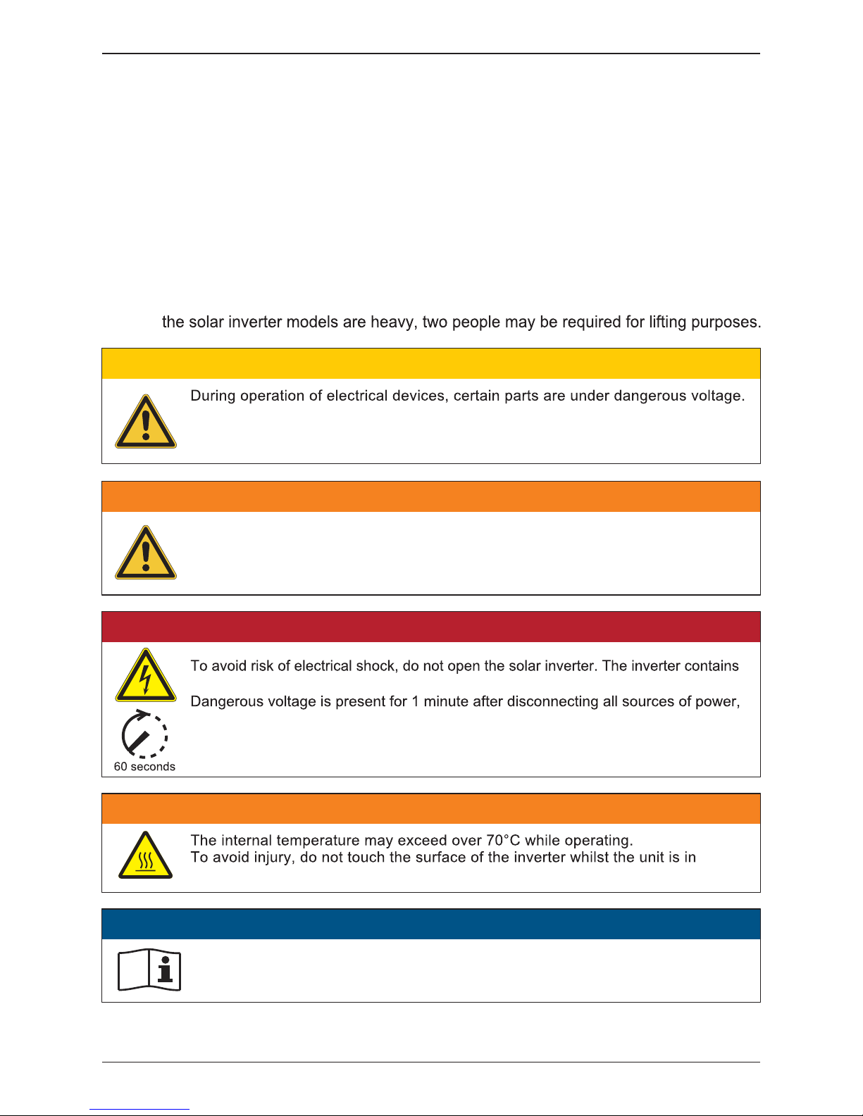
1.2 General Warnings / Notes on Safety
Careful handling of the product will contribute to it's service life durability and
reliability. Both are essential to ensure maximum yield from your product. As some of
DANGER!
no user-serviceable parts. Opening the inverter will void the warranty.
recommend 5 minutes for discharging.
Remember that the unit has a high leakage current.
The PE conductor MUST be connected prior to commencing operation.
Inappropriate handling can lead to physical injury and material damage.
Always adhere to the installation regulations. Installation may only be conducted
by certified electricians.
CAUTION !
WARNING !
Repair work on the device should ONLY be carried out by the manufacturer.
The inverter contains no user serviceable parts inside.
Please observe all points in the operation and installation manual. Isolate the device
from the grid and the PV modules before undertaking work on the device.
WARNING !
operation.
For operation and installation of inverter refer to the user manual.
Failure to comply with the instructions in this manual may void the warranty.
ATTENTION
5
General Information
Page 6
1.3 Validity
data and safety instructions of the following solar inverter models under the
DELTA brand.
1.4 Product Description
This device is a single-phase grid-tie solar inverter. It converts direct current (DC)
electricity from the PV array into single phase alternating current (AC) to supply
power to the load and feed the excess generated power back to the local grid.
This inverter allows for a wide voltage input range and has a high performance
(Digital Signal Processor) design reduces the complexity of the circuit and
electronic components. Please note that this device does not support off-grid
function. The features for H2.5 / H3 / H3A / H4A / H5A are shown below.
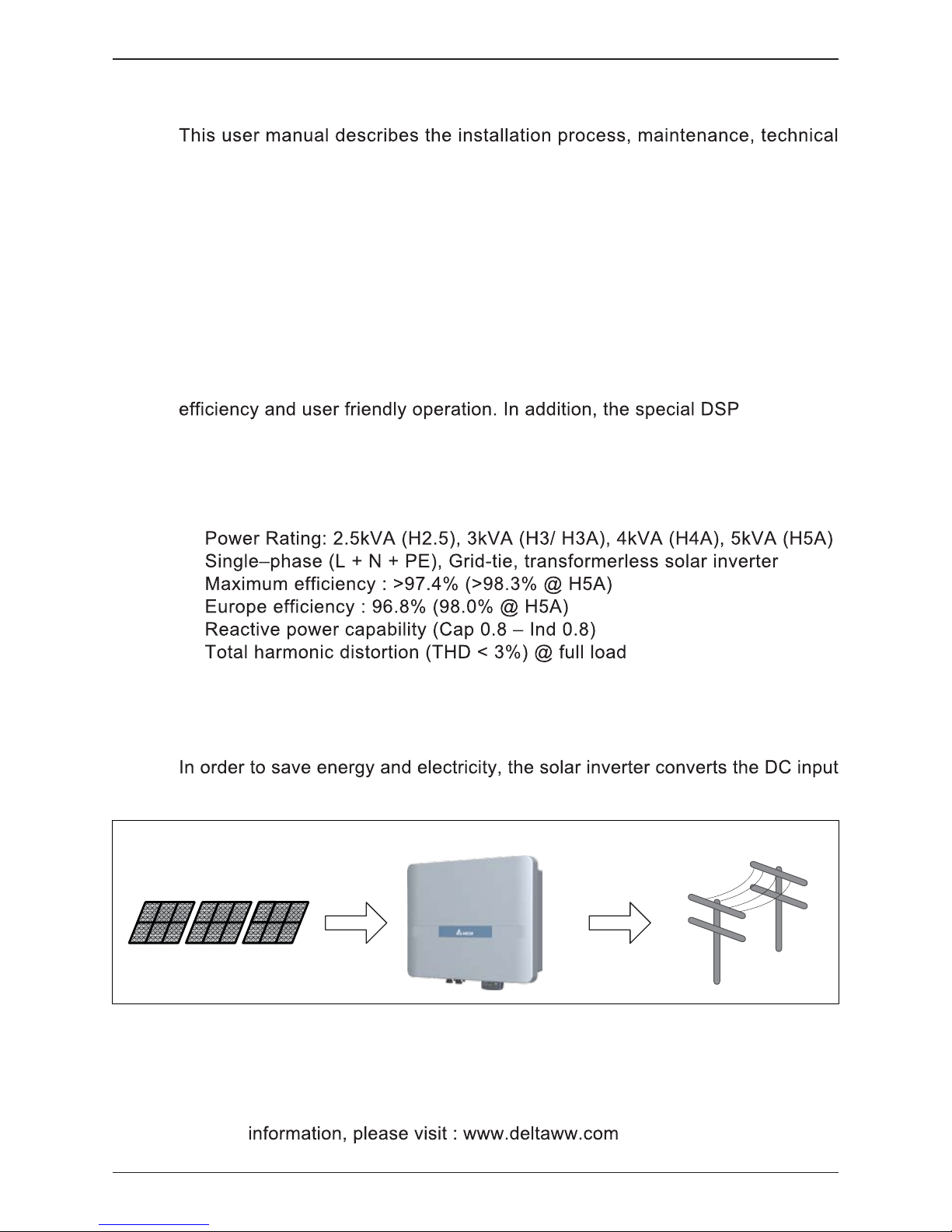
1.5 How it Works
The operation of a solar inverter is shown in Figure 1-1.
power supplied from the PV Array into single-phase AC output power to Grid.
1.6 Additional Information
For more detailed information for H2.5 / H3 / H3A / H4A / H5A or other related
product
Features
•
•
•
•
•
•
Figure 1-1 : Solar system operation illustration
PV Array Electrical GridSolar Inverter
•H3A •H4A •H5A•H3•H2.5
6
General Information
Page 7
2 Installation and Wiring
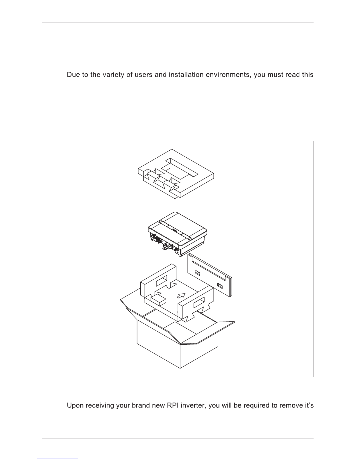
2.1 Instruction before Installation
manual thoroughly before installation. Installation of the unit and start-up
procedures must be carried out by an accredited technician.
protective packaging. This packaging consists of various materials that will need
to be disposed of according to the specific recycling marking printed on them.
2.2 Unpacking
Unpacking process is shown as Figure 2-1.
Figure 2-1 : Unpacking process
7
Installation and Wiring
Page 8
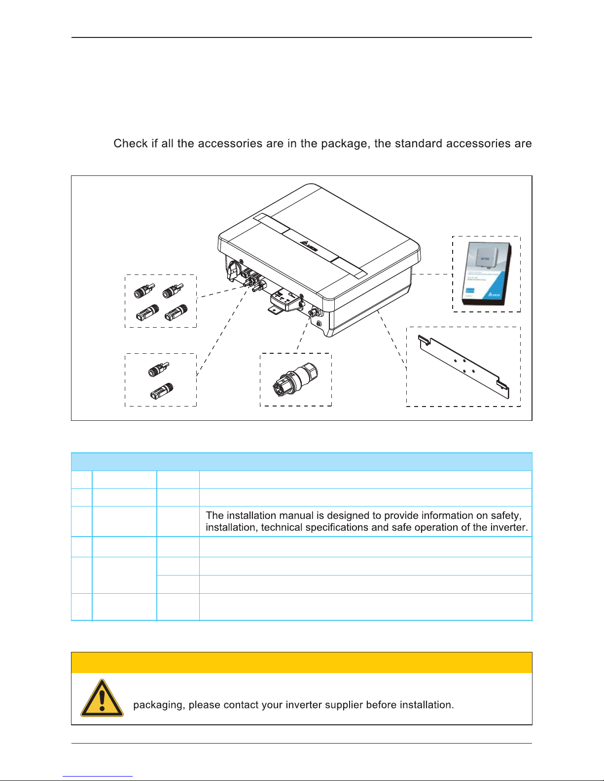
2.3 Package Inspection
Unforeseeable events causing damage or movement may occur during shipment.
Please check for damage on the packaging upon receiving your inverter.
Please check the model number and the serial number on the packaging is identical
with the model number and serial number on the unit itself.
listed as Table 2-1:
H2.5 / H3 / H3A / H4A / H5A
Object
PV Inverter
User
Manual
AC Plug
Wall-Mount
Bracket
Qty
1
1
1
1
Description
Solar inverter
Table 2-1 : Packing list
Connector for AC connection
DC Plug
①
②
③
⑤
④
①
②
③ ⑤
④
2 pairs
1 pairs
MC4 connector for DC connection for H3A / H4A / H5A models
MC4 connector for DC connection for H3 / H2.5 models
Wall-mount bracket to mount the solar inverter securely on the wall
If there is any visible damage to the inverter/accesories or any damage to the
CAUTION !
For H3A
H4A
H5A
For H3
H2.5
Figure 2-2 : Components of H2.5 / H3 / H3A / H4A / H5A
8
Installation and Wiring
Page 9
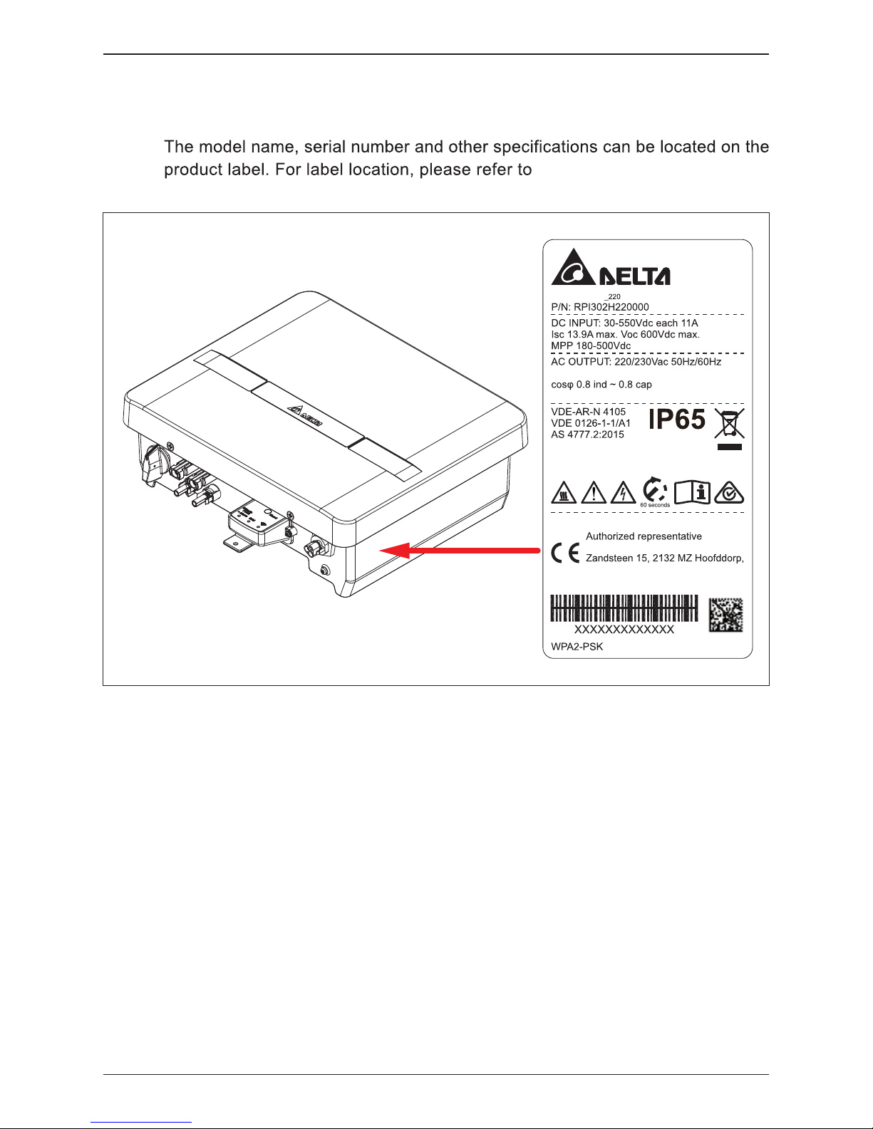
2.4 Identification Label
Users can identify the model name by the information on the product label.
Figure 2-3.
Figure 2-3 : The identification label
Model: H3A
3kVA nom. 14.3A max.
* 2.99kVA max. for AU/NZ
Protective class: I
OVC: 3
Inverter topology: transformer-less
Year & Month of Manufacturing: YYMM
Delta Electronics (Netherlands) B.V.
The Netherlands
Made in China
:DELTASOL
9
Installation and Wiring
Page 10

3 Product Overview
3.1 Dimensions
Figure 3-1 : Dimensions of H2.5 / H3 / H3A / H4A / H5A
Figure 3-2 : Inverter exterior objects
3.2 Function Introduction
Figure 3-2. The description for individual
objects can be found in sections 3.2.1.
Label
Grounding
AC connector
DC connectors
Comm. Interface
DC switch
91
91
H2.5 / H3 / H3A / H4A H5A
10
Product Overview
Page 11
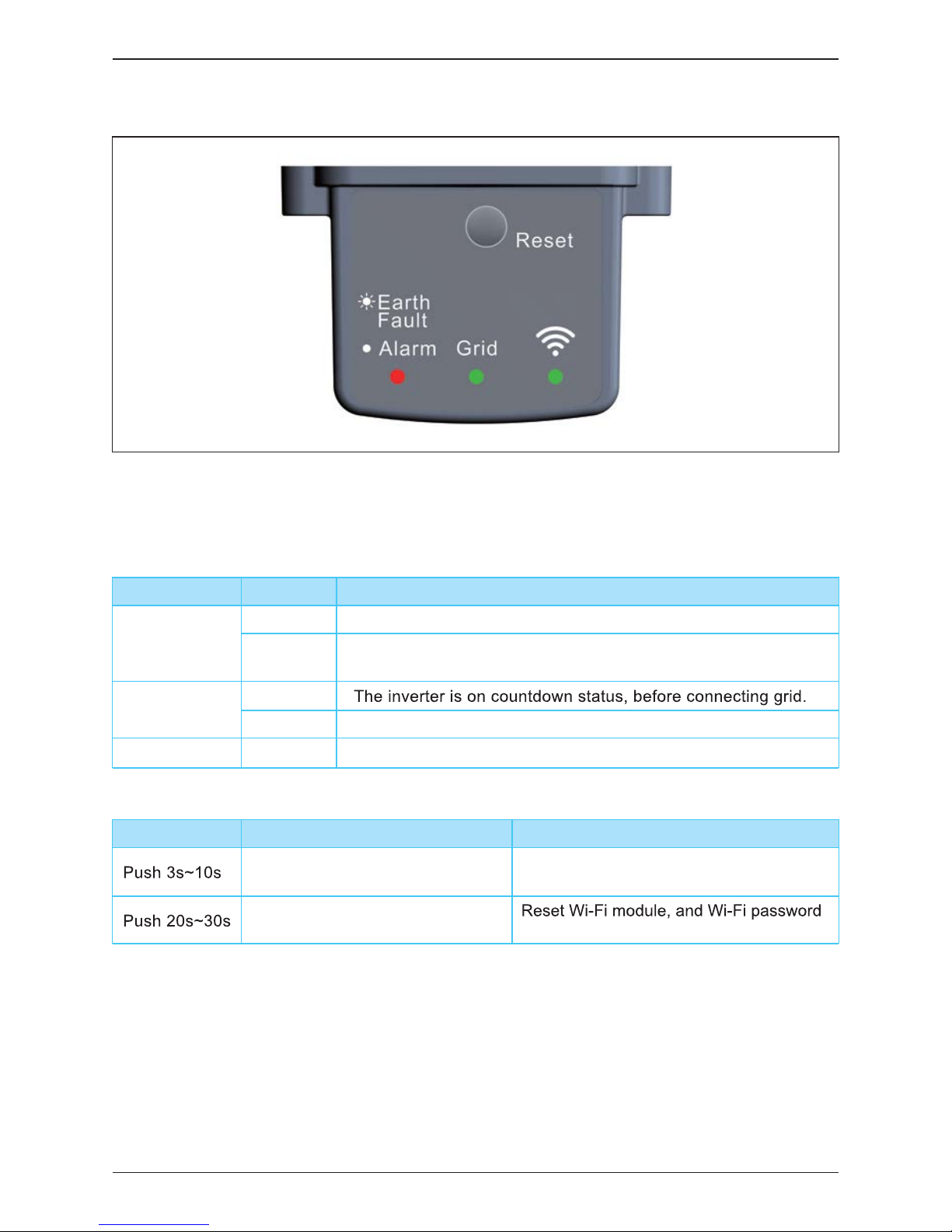
3.2.1 LED and Button
Figure 3-3 : LED and Button
Table 3-1 : LED and Reset button function
The LEDs indicate the operating state of the inverter.
The Reset button function
Status Explanation
steady on
The red LED glowing indicates error or fault.
( see 9.1 Error Message )
steady on The inverter is connected to the grid.
flashing The red LED flashing indicates error "E34:Insulation"
flashing
steady on The Wi-Fi module is on data transmission.
LED
Earth Fault
Alarm
Grid
Wi-Fi
Wi-Fi LED Status Explanation
Wi-Fi LED flashing once every
one seconds
returns to the default: DELTASOL
Wi-Fi LED flashing once every
half a second
Reset Wi-Fi module
Operation
11
Product Overview
Page 12
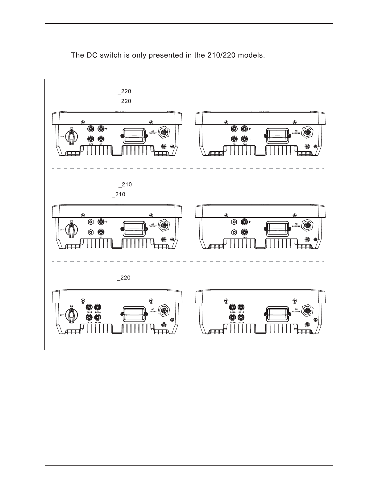
3.3 Inverter Comparison
Figure 3-4 : Inverter comparison
Model series 211/221 does not have the DC switch.
H3A
H4A
H3A_221
H4A_221
H2.5
H3
(No DC switch)
(No DC switch)
H2.5
_211
H3_211
H5A (No DC switch)H5A
_221
12
Product Overview
Page 13

4 Installation
4.1 Installation Location
The unit should not be installed in direct sunlight.
CAUTION !
4.2 Mounting
This unit is designed to be wall-mounted. Please ensure the installation is
perpendicular to the floor and the AC plug located at the base of the unit. Do not
install the device on a slanting wall. The dimensions of the mounting bracket
are shown in the figure below.
1.
2.Attach the inverter to the mounting bracket.
3.
Please refer to Figure 4-1.
WARNING !
Do not install the unit near or on flammable surfaces.
Mount the unit tightly on a solid/smooth surface.
13
Installation
Page 14

Figure 4-1 : Attaching the mounting bracket for H2.5 / H3 / H3A / H4A / H5A
Figure 4-2 : Correct and incorrect installation illustration
227
7.5
22.5
37.5
46
291
①
②
③
14
Installation
Page 15

• The bracket supplied with the unit is specially designed and should be the only
mounting device used for the unit.
• It is recommended to install the inverter in a suitable location which offers easy
and safe access for service and maintenance.
• Please leave an appropriate gap in between units when installing multiple solar
inverter systems.
• Please install solar inverter at eye level to allow easy observation for operation
and parameter setting.
• Ambient temperature for operation: -25°C~+60°C (power derating above 40°C).
CAUTION !
Please ensure the spacing requirement to allow for sufficient convective cooling.
It is essential to ensure sufficient space for product operation as shown in Figure 4-3.
Figure 4-3 : Adequate installation gap
>50cm
>50cm
>30cm>30cm >30cm
15
Installation
Page 16

5 Wiring
5.1 Preparation before Wiring
1. Ensure voltage values and polarities are correct.
2. When grounding the solar array, an isolation transformer is required due to
the H2.5 / H3 / H3A / H4A / H5A not having galvanic isolation between the
DC-input and AC-output.
3. The ground fault detection is a fixed internal setting. It cannot be modified.
4. Please refer to Figure 5-1 for connections. Inverter can accept DC inputs in
parallel.
5. According to IEC 62109-2, the PV modules need to have an IEC 61730 Class
A rating.
Figure 5-1 : Connection of a system for floating solar array
Wi-Fi Communication
3
2
DC Wiring
Parallel or
Separate
Distribution box*
* According to local regulations, DC circuit breaker may be necessary.
PV Array
1
AC Wiring
WARNING! SHOCK HAZARD
When the photovoltaic array is exposed to light, it supplies a DC voltage to the
Inverter, a shock hazard may exist due to output wires or exposed terminals.
To reduce the risk of shock during installation, cover the array with an opaque
(dark) material and ensure that the Disconnect Device in the inverter is set to OFF
before commencing any wiring.
16
Wiring
Page 17

5.2.1
Required protective devices and cable cross-sections
Power rating Upstream AC circuit breaker
H2.5
H3 / H3A
H4A / H5A
3.125 kVA
3.75 kVA
5 kVA
16A
20A
25A
Table 5-1: Recommended upstream protection
AC connector 96.031.4154.3 01K, Wieland Electric GmbH
Current rating
Min. / Max. cable diameter 10 ... 14 mm
Min. / Max. wire diameter 1.25 ... 4 mm
2
Recommended torque for terminal screws 0.8~1 N.m
WARNING !
Before commencing AC wiring, please ensure all AC circuit breakers are switched off.
5.2 AC Grid Connection : L + N + PE
The AC plug provided with the inverter has the following technical characteristics:
Read and follow the instructions delivered with the AC plug.
The AC plug delivered with the inverter can be used with flexible or rigid copper cable.
When calculating the cross section of the cable, consider:
Always follow the system installation requirements defined for your country!
17
Wiring
Page 18

5.3 DC Connection (from PV Array)
The maximum open circuit voltage of the PV Array must not exceed
500Vdc(H2.5) / 600Vdc (H3 / H3A / H4A / H5A).
CAUTION !
WARNING !
• When undertaking DC wiring, please ensure the correct polarities are connected.
• When undertaking DC wiring, please ensure that the DC isolator switch on the
PV array is OFF.
The isolator installed between the PV Array and inverter must meet the rating
of voltage higher than this device’s maximum input voltage.
NOTE
Figure 5-2 : AC plug illustration (96.031.4154.3 01K, Wieland Electric GmbH)
Screw connection :
Tightening torque
typ. 4+1 N.m
1.
2.
1.
2.
Detail
18
Wiring
Page 19

The RPI range of PV inverters uses genuine Multi-Contact® MC4 connectors.
DC wiring polarities have two components, Plus and Minus, which are shown in
Figure 5-3. The connection shall conform to the indication marked on inverter.
Table 5-2 : MC4 connectors
Figure 5-3 : DC Wiring illustration
PV-KBT 4/6 Ⅱ
PV-KST 4/6 Ⅱ
5.3.1 Asymmetrical Loading
The inverters (H3A / H4A / H5A) operate using two separate MPP trackers that can
handle both symmetrical and asymmetrical loads to allow for optimum adjustment.
This allows for the requirements of complex PV system designs to be fulfilled.
DC plugs and DC cables
The DC plugs for all DC connections are provided
along with the inverter.
If you want to order more or need a different
size, see the information in the following table.
MPP range with Max. power H3A
Symmetrical load 180~500V
Asymmetrical load 290~500V
Max. ratio for asymmetrical load 100/0% ; 0/100%
H4A
240~500V
380~500V
100/0% ; 0/100%
H5A
240~500V
380~500V
100/0% ; 0/100%
a
b
DC connectors on
the inverter
DC plugs for DC cable
a b
Multi-Contact
mm
2
mm
DC–
1,5/2,5
3–6 32.0010P0001-UR
5,5–9 32.0012P0001-UR
4/6
3–6 32.0014P0001-UR
5,5–9 32.0016P0001-UR
DC+
1,5/2,5
3–6 32.0011P0001-UR
5,5–9 32.0013P0001-UR
4/6
3–6 32.0015P0001-UR
5,5–9 32.0017P0001-UR
19
Wiring
Page 20

6
Active/Reactive Power Control and LVRT (Optional)
6.1.1 Power Limit
6.1 Active Power Control
Users can reduce inverter output power by a set percentage of actual or rated
power.
There are 2 settings for active power and 4 settings for reactive power control that can
be configured based on the requirement of the local network operator.
6.1.2 Power vs. Frequency
According to VDE-AR-N 4105 (5.7.3.3):
At frequencies between 50.2Hz and 51.5Hz, all adjustable power generation
systems shall reduce (for frequency increase) or increase (for frequency
decrease) the active power Pm generated instantaneously (at the time of
exceeding the mains frequency 50.2Hz; freezing the value on the current level)
with a gradient of 40% of Pm per Hertz).
According to CEI 0-21 (8.5.3.2):
Within a frequency range from 50.3Hz to 51.5Hz, all adjustable production
plants equipped with static converters have to be able to reduce the currently
generated active power in case
of an increase of the frequency with a variable
drop of 2% to 5% with a default value of 2.4% (with corresponds to a power
gradient of 83.3%/Hz).
User can set all necessary settings to meet the requirements from the network
operator. Please refer to actual Power vs. Frequency shown in Figure 6-1 for
the settings procedure.
The parameters are set according to the requirements of the selected country.
A change to the parameter settings may result in the approval being lost.
ATTENTION
20
Active/Reactive Power Control and LVRT (Optional)
Page 21

P
0
Gradient 40% Pm/Hz
Pm
Fstart(50,2Hz)
P
0
Fstart(50,3Hz)
Gradient 83.3% Pimax/Hz
Pimax
Figure 6-1 : Power vs. frequency characteristic
Power vs. frequency curve for VDE-AR-N 4105
Power vs. frequency curve for CEI-021
6.2 Reactive Power Control
The setting value is either:
•
•
(VDE-AR-N 4105 ,CEI 0-21)
• fixed reactive power in Var.(CEI 0-21)
• reactive power/voltage characteristic Q(U). (CEI 0-21)
21
Active/Reactive Power Control and LVRT (Optional)
Page 22

6.2.1
Users can set the power factor from Cap 0.8 to Ind 0.8 (inverter would stop
reactive power control if output power is below 20% rated power).
6.2.3 Fixed Reactive Power InVAR(CEI 0-21)
Once user enables this method, the inverter will deliver reactive power (i.e. Q)
consistent with that of the fixed reactive power setting.
The setting range is from Cap 53% to Ind 53%.
Once the user enables this method, the user can set Q vs. Grid voltage operation
curve as in Figure 6-3 below.
6.2.4
Reactive Power/ Voltage Characteristic Q(U)(CEI 0-21)
Once user enables this method, the inverter will deliver reactive power according
to output active power at that moment. Figure 6-2 is an example.
Cap 0.9
Ind 0.9
P/ Pn
1
cos
0.5
P1
P2
Upper limit
lower limit
0.2
No cos ( P )
is allowed
22
Active/Reactive Power Control and LVRT (Optional)
Page 23

U
Q/Sn
(%)
U1s
U2s
U1i
U2i
Qmin(48.4%)
Qmax(48.4%)
Figure 6-3 : Q(U) characteristic
U
Q/Sn
(%)
U1s
U2s
U1i
U2i
Type A
Type B
23
Active/Reactive Power Control and LVRT (Optional)
Page 24

6.3 Low Voltage Ride Through (LVRT)
According to CEI 0-21, 8.5.1
To avoid undue separation from the network if voltage dips occur, a generation
system with over 6 kW total power must be able to comply with certain functional
requirements, which are known as LVRT (Low Voltage Ride Through) in
international literature.
Zone 1 : The Inverter doesn't disconnect from the grid.
Zone 2 : The Inverter may temporarily interrupt the supply of active and reactive
power supplied before the breakdown.
Zone 3 : The inverter disconnect from the grid.
100%
0
time ( ms )
U
grid
/
U
n
2
1
90 %
40 %
3
200 400
0%
85 %
110%
Figure 6-4 : LVRT characteristic
24
Active/Reactive Power Control and LVRT (Optional)
Page 25

6.4 Digital Input
To implementation of power management, the digital input interface receives
the specifications of the network operator via a ripple control receiver or a DRED.
H2.5/H3/H3A/H4A/H5A can access these command via PPM DC1.
• Germany : The active power limitation in the stages 0%, 30%, 60% and 100%
• Italy : Power output of Max 6KW for PV plant installation.
Remote shutdown
Narrow Frequency limits between 49.5 Hz to 50.5Hz.
• Australia and New Zealand:
The inverter support the demand response mode (DRMs).
DRM 0 - Operate the disconnection device.
DRM 5 - Do not generate power.
DRM 6 - Do not generate at more than 50% of rated power.
DRM 7 - Do not generate at more than 75% of rated power.
And sink reactive power.
DRM 8 - Increase power generation.
(subject to constraints from other active DRMs)
• Customer : User defined.
Figure 6-5 : Digital input via PPM DC1
Figure 6-6 : Digital input on PPM DC1
Com/
DRM0
PPM DC1 I/O port
H2.5/H3/H3A/H4A/H5A
PPM DC1
(DRMs command received)
DRM
4/8
DRM
2/6
Dry
2
CAN-L
RS-485-BRS-485
-B
GND
Ref/
Gen
DRM
3/7
DRM
1/5
Dry
1
CAN-H
RS-485-ARS-485
-A
+12V
Wi-Fi
Wi-Fi
DRED
Utility
Agent
DRM
Wi-Fi
25
Active/Reactive Power Control and LVRT (Optional)
Page 26

7 Turning the PV inverter on/off
WARNING !
The internal temperature may exceed over 70°C while operating.
To avoid injury, do not touch the surface of the inverter whilst the unit is
in operation.
After installation, please ensure the AC, the DC and communication
connection are correct. When enough power is generated from the PV
array, the device will operate automatically and will initial ‘self-test’.
This self-test takes approximately 2 minutes and will occur at first start-up
of the day.
7.1.1 PV Array DC Voltage Checking
7.1 Start-up Procedures
Firstly, uncover the PV arrays and expose them to full sunlight. Please note, the
sunlight must be intense enough to produce the required output voltage for the
inverter to start up.
Measure the PV array open circuit DC voltage across the DC positive (+) and
negative (-) terminals.
7.1.2 AC Utility Voltage Checking
Using an AC voltmeter, measure the AC open circuit utility voltage between L1 (L)
and L2 (N) Ensure the voltage is at approximately the nominal value. The inverter
operates with a line-to-line voltage range around the nominal value.
Refer to page 33 "11. Technical data” output section for the utility voltage
operating range for your inverter model.
26
Turning the PV inverter on/off
Page 27

7.1.3 Starting up the Inverter
1.Switch on the PV Array switch and DC switch (with DC switch model) to
connect PV Array.
2.Switch on AC circuit breaker to connect electricity grid.
3.Communication Module
The Communication Module supports the communication with the device with
Wi-Fi function.(e.g., smart phone, tablet ect.)
Wi-Fi communication
1. Turn on the device’s Wi-Fi function.
2. Select the inverters' Wi-Fi SSID: Delta-[serial number]
(e.g. Delta-O4L16A00001W0 ; See Inverter ” The identification label”)
3. Enter the Wi-Fi password: DELTASOL
(The Default password is also printed on the identification label)
4. Use the "MyDeltaSolar" APP (You can download the APP via google
play or App Store)
Please note:
(1) The product only support one device communicating at the same
time.
(2) If the Wifi password is forgotten, press and hold the Reset Button
10s~20s to return the Default password to (”DELTASOL”).
4.First Start-up Country Selection
Upon first start-up of the inverter, country selection is required. You can set
country and time via "MyDeltaSolar" APP.
27
Turning the PV inverter on/off
Page 28

8 Maintenance
WARNING !
Before any maintenance, please switch AC and DC power off to avoid risk of
electronic shock.
In order to ensure normal operation of the inverter, please check the unit regularly.
Check that all terminals, screws and cables are connected and appear as they did upon
installation. If there are any impaired or loose parts, please contact your solar installer
immediately. Ensure that there are no foreign objects in the path of the heat outlet and
keep the unit and it’s surroundings clean and tidy at all times.
28
Maintenance
Page 29

Error
Message
E01: OFR
E02: UFR
E09: No Grid
E10: UVR
1. Actual utility frequency is higher
than the OFR setting
2. Incorrect country setting
3. Detection circuit malfunction
1. Actual utility frequency is lower
than the UFR setting
2. Incorrect country or Grid setting
3. Detection circuit malfunction
1. AC breaker is OFF
2. AC plug disconnected
3. Internal fuses are broken
1. Actual utility voltage is higher the
UVR setting
2. Incorrect country or Grid setting
3. Detection circuit malfunction
1. Check the utility frequency on the
inverter terminal
2. Check country setting
3. Check the detection circuit inside
the inverter
1. Check the utility frequency on the
inverter terminal
2. Check country & Grid setting
3. Check the detection circuit inside
the inverter
1. Switch on AC breaker
2.
Check the connection in AC plug and
make sure it connects to inverter
3. Replace fuses and check all
switching devices in boost &
inverter stages
1. Measure the utility AC voltage to
the inverter terminal.
2. Check country & Grid setting
3. Check the detection circuit inside
the inverter
E11: OVR
1. Actual utility voltage is higher
than the OVR setting
2. Incorrect country or Grid setting
3. Detection circuit malfunction
1. Measure the utility AC voltage to
the inverter terminal.
2. Check country & Grid setting
3. Check the detection circuit inside
the inverter
E13: OVR-Slow
1. Actual utility voltage is over
than the OVR setting
2. Incorrect country or Grid setting
3. Detection circuit malfunction
1. Check the utility voltage on the
inverter terminal
2. Check country & Grid setting
3. Check the detection circuit inside
the inver
ter
E26: OFR-Slow
1. Actual utility frequency is over the
OFR setting
2. Incorrect country or grid setting
3. Detection circuit malfunction
1. Check the utility frequency on the
inverter terminal
2. Check country setting
3. Check the detection circuit inside
the inverter
E27: UFR-Slow
1. Actual utility frequency is under
the UFR setting
2. Incorrect country or Grid setting
3. Detection circuit malfunction
1. Check the utility frequency on the
inverter terminal
2. Check country & Grid setting
3. Check the detection circuit inside
the inverter
Possible cause Action
9.1 Error Message & Trouble Shooting
9 Error Message and Trouble Shooting
29
Error Message and Trouble Shooting
Page 30

Error
Message
E28: UVR-Slow
E30: OVR(PV)
E34: Insulation
1. Actual utility voltage is under the
UVR setting
2. Incorrect country or Grid setting
3. Detection circuit malfunction
1. Actual Solar voltage is over
510Vdc (H2.5) or
560Vdc (H3/ H3A/ H4A)
2. Detection circuit malfunction
1. PV array insulation fault
2. Large PV array capacitance
between Plus to Ground or Minus
to Ground or both.
3. Detection circuit malfunction
1. Check the utility voltage on the
inverter terminal
2. Check country & Grid setting
3. Check the detection circuit inside
the inverter
1.
Modify the solar array configuration
and make the Voc less than
500Vdc (H2.5) or
550Vdc (H3/ H3A/ H4A)
2. Check the detection circuit inside
the inverter
1.
Check the insulation of Solar inputs
2. Check the capacitance, dry PV
panel if necessary
3. Check the detection circuit inside
the inverter
Possible cause Action
Fault
Message
F01: DC Injection
F05: NTC OTP
F06:
NTC0 Circuit Fail
F07: NTC LTP
1. Utility waveform is abnormal
2. Detection circuit malfunction
1. The ambient temp. is over 60℃
2. Detection circuit malfunction
1. Ambient temp. >100℃ or <-40℃
2. Detection circuit malfunction
1. Ambient temp. <-30℃
2. Detection circuit malfunction
1. Check the utility waveform.
Grid connection of inverter need
to be far away from non-linear load
if necessary
2. Check the detection circuit inside
the inverter
1. Check the installation ambient
temperature and environment
2. Check the detection circuit inside
the inverter
1. Check the installation ambient
temperature and environment
2. Check the detection circuit inside
the inverter
1. Check the installation ambient
temperature and environment
2. Check the detection circuit inside
the inverter
F09:
Ntc2 Circuit Fail
1. Ambient temp. >100℃ or <-40℃
2. Detect
ion circuit malfunction
1. Check the installation ambient
temperature and environment
2. Check the detection circuit inside
the inverter
Possible cause Action
Table 9-1 : Error Message
30
Error Message and Trouble Shooting
Page 31

Fault
Message
F15: HW ADC1
F16: HW ADC2
F17: HW ADC3
F19: HW ADC5
1.
Auxiliary power circuitry malfunction
2. Detection circuit malfunction
1.
Auxiliary power circuitry malfunction
2. Detection circuit malfunction
1.
Auxiliary power circuitry malfunction
2. Detection circuit malfunction
1.
Auxiliary power circuitry malfunction
2. Detection circuit malfunction
1. Check the auxiliary circuitry inside
the inverter
2. Check the detection circuit inside
the inverter
1. Check the auxiliary circuitry inside
the inverter
2. Check the detection circuit inside
the inverter
1. Check the auxiliary circuitry inside
the inverter
2. Check the detection circuit inside
the inverter
1. Check the auxiliary circuitry inside
the inverter
2. Check the detection circuit inside
the inverter
F20:
Efficiency
Abnormal
1. The calibration is incorrect
2.
Current feedback circuit is defective
1. Check the accuracy of current and
power
2. Check the current feedback circuit
inside the inverter
F23:
Comm. Fault
(Dis.)
1. DSP is idling
2. The communication connection is
disconnected
3. The communication circuit
malfunction
1. Check reset and crystal in DSP
2. Check the connection between
DSP and COM
M
3. Check the communication circuit
F24:
RCMU Over Rating
1. PV array insulation fault
2. Large PV array capacitance
between Plus to Ground or Minus
to Ground
3. Either side of boost driver or boost
choke malfunction
4. Detection circuit malfunction
1.
Check the insulation of Solar inputs
2.
Check the capacitance (+ <-> GND
& - <-> GND), must < 2.5uF. Install
an external transformer if necessary
3. Check boost driver & boost choke
4. Check the detection circuit inside
the inverter
F27:
RCMU Circuit Fail
1. RCMU is disconnected
2. Detection circuit malfunction
1.
Check the RCMU connection inside
the inverter
2. Check the detection circuit inside
the inverter
F28:
Relay Test Short
1. One or more relays are sticking
2. The driver circuit for the relay
malfunction
1. Replace the defective relay(s)
2. Check the driver circuit inside the
inverter
F29:
Relay Test Open
1. One or more relays are abnormal
2. The driver circuit for the relay
malfunction
3. The detection accuracy is not
correct for Vgrid and Vout
1. Replace the defective relay(s
)
2. Check the driver circuit inside the
inverter
3. Check the Vgrid and Vout voltage
detection accuracy
Possible cause Action
31
Error Message and Trouble Shooting
Page 32

Fault
Message
F35:
HW Bus OVR
F37: OOCP
F42:
CT sensor Fail (A)
F56:
HW incompat.
1. Driver for boost is defective
2. Voc of PV array is over
510Vdc (H2.5) or
560Vdc (H3/ H3A/ H4A)
3. Surge occurs during operation
4. Detection circuit malfunction
Detection circuit malfunction
1. Inverter choke Fail
2. Output Filter Fail
3. Detection circuit malfunction
HW power rating incorrect
1. Check the driver circuit for boost
inside the inverter
2. Modify the solar array setting,
and make the Voc less than
500Vdc (H2.5) or
550Vdc (H3/ H3A/ H4A)
3. N/A
4. Check the detection circuit inside
the inverter
Check the detection circuit inside the
inverter
1. Check Inverter choke inductance.
2. Check output filter capacitance.
3. Check the detection circuit inside
the inverter
Check comm. HW power rating info.
F60: IOCP(PV1)
1.
Switching device in boost is defective
2. Driver for boost is defective
3. Input current detection circuit
malfunction
1. Check
all switching device in boost
2. Check the driver circuit for boost
inside the inverter
3. Check
input current detection circuit
1. Check
all switching device in boost
2. Check the driver circuit for boost
inside the inverter
3. Check
input current detection circuit
F61: IOCP(PV2)
1.
Switching device in boost is defective
2. Driver for boost is defective
3. Input current detection circuit
malfunction
Possible cause Action
Table 9-2 : Fault Message
32
Error Message and Trouble Shooting
Page 33

10 De-Commissioning
De-Commissioning Procedure:
If necessary to put the device out of operation for maintenance and/or storage, please
follow the instructions below.
WARNING !
To avoid injuries, please follow this procedures
1. Switch off AC circuit breaker to disconnect from electricity grid.
2. Switch off the PV Array switch to disconnect from PV Array.
3. Use proper voltage meter to confirm that the AC and DC power are
disconnected from the unit.
4.
Remove the AC wiring immediately to completely disconnect from electricity grid.
5. Remove the DC wiring to disconnect from PV Array.
6. After completing all of the above steps, the inverter can be removed.
33
De-Commissioning
Page 34

11 Technical Data
11.1 Specifications
Model
1
H2.5_210
H2.5_211
GENERAL
H3_210
H3_211
H3A_220
H3A_221
H4A_220
H4A_221
H5A_220
H5A_221
Enclosure
Operating temperature
Relative humidity
Galvanic isolation
Safety class
Overvoltage category
Flicker impedance
Three-phase combinations
Max. input voltage
Operating voltage range
MPP range (rated power)
Normal voltage
MPP tracker
Startup voltage
Input connection
Max. inverter backfeed
current to the array
Maximum input current
Max. short circuit current
per MPPT
Powder-coated aluminium
-25~60°C, full power up to 40°C
Operating Altitude 2000m
0% – 95% non-condensing.
Environmental category Outdoor, wet locations
No (TL Topology)
Class I metal enclosure with protective earth
Pollution degree Internal: II, External: III
AC output: III, DC input: II
No
500 Vdc 600 Vdc
30~500 Vdc
11 A
290-500Vdc
350 Vdc
30-550Vdc
240~470 Vdc 240-500Vdc180-500Vdc
11Adc for each /
18Adc for total
1
11Adc for each /
22Adc for total
2
13.9 A
0A
35 Vdc
MC4, 1 pairs MC4, 2 pairs
DC INPUT (Solar side)
34
Technical Data
Page 35

Model
1
AC OUTPUT (Grid side)
Nominal output power
2
Maximum power
Nominal output current
Maximum output
fault current
Maximum output
over current protection
Frequency
Total harmonic distortion
3
Power factor
3
Peak efficiency
EU efficiency
Output connection
Voltage 230Vac -20%~+22%
Max. output current
16A
16A
20A
20A
Current (inrush)
(A, peak and duration)
30A peak, 1ms
50/60 Hz
<3% @Rated power
>0.99 @Rated power
97.5%
96.8%
98.3%
98.0%
IP 67 single-phase
2500VA 3000VA 4000VA
2500VA 3000VA 4000VA
5000VA
5000VA
10.9 A 17.4 A
13.9 A 18.6 A
25A
25A
22 A
24 A
13 A
14.3 A
Housing
Cooling
IP rating
External communication
Weight
Dimensions
Die casting
convection cooling
IP65
Wi-Fi
10 kg 11 kg 12 kg
380 × 318 × 130 mm
MECHANISM
H2.5_210
H2.5_211
H3_210
H3_211
H4A_220
H4A_221
H5A_220
H5A_221
H3A_220
H3A_221
35
Technical Data
Page 36

H2.5_210
H2.5_211
H3_210
H3_211
H4A_220
H4A_221
H5A_220
H5A_221
H3A_220
H3A_221
Model
1
REGULATIONS & DIRECTIVES
Safety
Grid interface
4
Harmonics
Immunity
Immunity
ESD
EFT
Surge
CS
PFMF
Emission IEC 61000-6-4, IEC 61000-6-3
Variations and flicker
EN 61000-6-2
IEC 61000-4-2
RS IEC 61000-4-3
IEC 61000-4-4
IEC 61000-4-5
IEC 61000-4-6
IEC 61000-4-8
IEC 62109-1 / -2
CE compliance
VDE AR-N 4105 / VDE 0126-1-1 / AS4777 / G83-2 / G59-3 / EN50438 /
VFR2014 / C10/C11 / UTE C15-712-1 / IEC61683 / IEC61727 / IEC62116
EN 61000-3-12
EN 61000-3-11
Table 11-1 : Specifications
1:
H2.5_210/ H3_210/ H3A_220/ H4A_220/ H5A_220 : The product is with DC switch
H2.5_211/ H3_211/ H3A_221/ H4A_221/ H5A_221 : The product is without DC switch
2:
(a) H2.5 : 2.49kVA max. for Australia (AU / NZ)
(b) H3 / H3A : 2.99kVA max. for Australia (AU / NZ)
(c) H5A : 4.99kVA max. for Australia (AU / NZ)
(d) H5A : 4.6kVA max. for Germany (DE)
3: reactive power control disabled
4: not support AS4777.2:2015 Single-phase inverters used in three-phase combinations
36
Technical Data
Page 37

Version 07171221
50 13247 804
 Loading...