

Page 1

Industrial Automation Headquarters
Delta Electronics, Inc.
Taoyuan Technology Center
No.18, Xinglong Rd., Taoyuan City,
Taoyuan County 33068, Taiwan
TEL: 886-3-362-6301 / FAX: 886-3-371-6301
Asia
Delta Electronics (Jiangsu) Ltd.
Wujiang Plant 3
1688 Jiangxing East Road,
Wujiang Economic Development Zone
Wujiang City, Jiang Su Province, P.R.C. 215200
TEL: 86-512-6340-3008 / FAX: 86-769-6340-7290
Delta Greentech (China) Co., Ltd.
238 Min-Xia Road, Pudong District,
ShangHai, P.R.C. 201209
TEL: 86-21-58635678 / FAX: 86-21-58630003
Delta Electronics (Japan), Inc.
Tokyo Ofce
2-1-14 Minato-ku Shibadaimon,
Tokyo 105-0012, Japan
TEL: 81-3-5733-1111 / FAX: 81-3-5733-1211
DVS Managed Industrial Rack Mount Ethernet Switch User Manual
Delta Electronics (Korea), Inc.
1511, Byucksan Digital Valley 6-cha, Gasan-dong,
Geumcheon-gu, Seoul, Korea, 153-704
TEL: 82-2-515-5303 / FAX: 82-2-515-5302
Delta Electronics Int’l (S) Pte Ltd.
4 Kaki Bukit Ave 1, #05-05, Singapore 417939
TEL: 65-6747-5155 / FAX: 65-6744-9228
Delta Electronics (India) Pvt. Ltd.
Plot No 43 Sector 35, HSIIDC
Gurgaon, PIN 122001, Haryana, India
TEL : 91-124-4874900 / FAX : 91-124-4874945
Americas
Delta Products Corporation (USA)
Raleigh Ofce
P.O. Box 12173,5101 Davis Drive,
Research Triangle Park, NC 27709, U.S.A.
TEL: 1-919-767-3800 / FAX: 1-919-767-8080
Delta Greentech (Brasil) S.A.
Sao Paulo Ofce
Rua Itapeva, 26 - 3° andar Edicio Itapeva One-Bela Vista
01332-000-São Paulo-SP-Brazil
TEL: 55 11 3568-3855 / FAX: 55 11 3568-3865
Europe
Delta Electronics (Netherlands) B.V.
Eindhoven Ofce
De Witbogt 20, 5652 AG Eindhoven, The Netherlands
TEL : +31 (0)40-8003800 / FAX : +31 (0)40-8003898
DVS
Managed Industrial
Rack Mount Ethernet Switch
User Manual
Product Model:
DVS-328 series
*We reserve the right to change the information in this manual without prior notice.
2017-01-12
www.deltaww.com
Page 2

DVS Managed Indu strial
Rack Mount Ethernet Switch User Manual
Table of Contents
Chapter 1 Introduction
1.1 Feature ...................................................................................... 1-2
1.1.1 High Performance Network Technology .................................... 1-2
1.1.2 Industrial Grade Reliability ..................................................... 1-2
1.1.3 Robust Design ...................................................................... 1-2
1.1.4 Front Panel Ports and LEDs .................................................... 1-3
1.2 SFP Module Installation ................................................................ 1-3
1.3 Package Checklist ....................................................................... 1-4
1.4 MTBF (Mean Time Between Failures) ............................................. 1-4
Chapter 2 User Interface Introduction
2.1 USB Console Configuration ........................................................... 2-2
2.2 Telnet Console Conf iguration ........................................................ 2-5
2.3 Web Browser Configuration .......................................................... 2-6
Chapter 3 Featured Functions
3.1 Basic Setting .............................................................................. 3-5
3.1.1 System Information .............................................................. 3-5
3.1.2 Network Interface ................................................................. 3-6
3.1.2.1 IPv4 Network Configuration ............................................... 3-6
3.1.2.2 IPv6 Network Configuration ............................................... 3-7
3.1.2.3 IPv6 Network Neig h bor ..................................................... 3-8
3.1.3 Port Settings ........................................................................ 3-9
3.1.3.1 Port Settings....................................................................
3.1.3.2 LAG Settings ................................................................. 3-10
3-9
3.1.4 Time ................................................................................. 3-11
3.1.4.1 SNTP Scalars Configuration ............................................. 3-11
3.1.4.2 SNTP Unicast Server Configuration ................................... 3-12
3.1.5 DHCP/BOOTP Settings ......................................................... 3-13
3.1.5.1 DHCP Server ................................................................. 3-13
3.1.5.2 DHCP Relay ................................................................... 3-17
3.1.5.3 DHCP L2 Relay ............................................................... 3-19
i
Page 3

3.1.6 DNS .................................................................................. 3-23
3.1.6.1 DNS Configuration ......................................................... 3-23
3.1.6.2 Host Configuration ......................................................... 3-24
3.1.7 System File Update ............................................................. 3-24
3.1.7.1 Download File ................................................................ 3-24
3.1.7.2 Upload File .................................................................... 3-26
3.1.8 Management Access ............................................................ 3-28
3.1.8.1 HTTP Configuration ........................................................ 3-28
3.1.8.2 HTTPS .......................................................................... 3-28
3.1.8.3 SSH Configuration .......................................................... 3-31
3.1.8.4 Telnet Configuration ....................................................... 3-32
3.1.8.5 Console Port .................................................................. 3-33
3.1.9 Loopback-Detection............................................................. 3-33
3.1.9.1 Global Configuration ....................................................... 3-33
3.1.9.2 Port Configuration .......................................................... 3-34
3.1.10 EtherNet/IP ..................................................................... 3-35
3.2 SNMP Manager ......................................................................... 3-35
3.2.1 SNMP v1/v2c ...................................................................... 3-35
3.2.1.1 Community Configuration ................................................ 3-35
3.2.1.2 Trap Configuration .......................................................... 3-36
3.2.1.3 Trap Flags ..................................................................... 3-37
3.2.2 SNMP v3 ............................................................................ 3-38
3.2.2.1 User Configuration ......................................................... 3-38
3.3 Network Redundancy................................................................. 3-40
3.3.1 STP ................................................................................... 3-40
3.3.1.1 STP Configuration .......................................................... 3-44
3.3.1.2 CST Configuration .......................................................... 3-45
3.3.1.3 CST Port Configuration ................................................... 3-48
3.3.1.4 CST Port Status ............................................................. 3-50
3.3.1.5 MST Configuration .......................................................... 3-52
3.3.1.6 MST Port Status ............................................................. 3-53
3.3.1.7 STP Statistics ................................................................ 3-55
3.3.2 Redundancy ....................................................................... 3-57
3.3.2.1 ONE RING Configuration ................................................. 3-57
3.3.2.2 ONE CHAIN Configuration ............................................... 3-57
3.3.2.3 ONE COUPLING Configuration .......................................... 3-58
3.3.2.4 Redundancy Cruiser ....................................................... 3-59
ii
Page 4

3.4 Virtual LANs ............................................................................. 3-61
3.4.1 VLAN Mode Configuration ..................................................... 3-62
3.4.2 VLAN Configuration ............................................................. 3-62
3.4.3 VLAN Membership ............................................................... 3-63
3.4.4 VLAN Status ....................................................................... 3-64
3.4.5 Port PVID Configuration ....................................................... 3-64
3.4.6 GVRP Configuration ............................................................. 3-65
3.4.7 Double VLAN Configuration .................................................. 3-66
3.4.8 MAC Based VLAN ................................................................ 3-68
3.4.9 IP Subnet Based VLAN ......................................................... 3-68
3.5 Multicast Filtering ...................................................................... 3-69
3.5.1 IGMP Snooping Configuration ............................................... 3-70
3.5.2 IGMP VLAN Configuration ..................................................... 3-71
3.5.3 IGMP Snooping Multicast Forwarding Table ............................. 3-72
3.5.4 Multicast MAC Address Configuration ..................................... 3-72
3.5.5 GMRP Configuration............................................................. 3-73
3.5.6 Multicast Forwarding Table ................................................... 3-74
3.6 Traffic Prioritization ................................................................... 3-74
3.6.1 QoS ................................................................................... 3-75
3.6.1.1 QoS Setting
................................................................... 3-75
3.6.1.2 CoS Queue Mapping ....................................................... 3-76
3.6.1.3 DSCP Queue Mapping ..................................................... 3-76
3.7 Traffic Control ........................................................................... 3-78
3.7.1 Port Protected..................................................................... 3-78
3.7.2 Port Isolation Configuration .................................................. 3-78
3.8 Port Bandwidth ......................................................................... 3-79
3.8.1 Storm Control ..................................................................... 3-79
3.8.1.1 Storm Control Setting ..................................................... 3-79
3.8.1.2 Rate Limiting ................................................................. 3-81
3.9 Port Trunking ............................................................................ 3-82
3.9.1 LAG ................................................................................... 3-82
3.9.1.1 LAG Membership ............................................................ 3-82
3.9.1.2 LAG Information ............................................................ 3-83
3.10 Access Control List ................................................................. 3-84
3.10.1 MAC ACL ......................................................................... 3-84
3.10.1.1 MAC Rules ..................................................................... 3-85
3.10.1.2 MAC Binding Configuration .............................................. 3-87
3.10.2 Binding Table ................................................................... 3-88
iii
Page 5

3.11 Security Settings ................................................................... 3-88
3.11.1 Security .......................................................................... 3-88
3.11.1.1 Port Security ................................................................. 3-88
3.11.1.2 IP Source ...................................................................... 3-90
3.11.1.3 802.1X ......................................................................... 3-91
3.11.2 Management Security ....................................................... 3-96
3.11.2.1 Local Users Management ................................................ 3-96
3.11.2.2 RADIUS Server Confi g .................................................... 3-97
3.11.2.3 RADIUS Statistics........................................................... 3-98
3.11.2.4 TACACS+ Server ............................................................ 3-99
3.11.2.5 TACACS+ AS ................................................................. 3-99
3.11.2.6 Login Authentication ..................................................... 3-100
3.11.2.7 Login User Sessions ..................................................... 3-100
3.11.3 Denial of Service ........................................................... 3-101
3.12 Monitoring Settings .............................................................. 3-102
3.12.1 MAC Address Table ......................................................... 3-102
3.12.2 SFP DDM (Only for SFP Module) ....................................... 3-104
3.12.3 System CPU Status ........................................................ 3-104
3.12.4 Interface Statistics ......................................................... 3-105
3.12.5 ARP Configure ............................................................... 3-105
3.12.5.1 Basic .......................................................................... 3-105
3.12.6 RMON .......................................................................... 3-106
3.12.6.1 Basic Settings .............................................................. 3-106
3.12.6.2 Alarms ........................................................................ 3-106
3.12.6.3 Events ........................................................................ 3-108
3.12.6.4 Event Log ................................................................... 3-108
3.12.6.5 History ....................................................................... 3-109
3.12.6.6 RMON Ethernet Statistics .............................................. 3-109
3.12.6.7 Ethernet History Statistics ............................................. 3-111
3.12.7 SYSLOG ........................................................................ 3-113
3.12.7.1 Show Logs .................................................................. 3-113
3.12.7.2 Logs Configuration ....................................................... 3-113
3.12.7.3 Syslog Fwd Table ......................................................... 3-115
3.12.7.4 Syslog Email Configuration ............................................ 3-116
3.12.7.5 Syslog Email Alarm Table .............................................. 3-117
3.13 Diagnostic Settings .............................................................. 3-119
3.13.1 LLDP ............................................................................ 3-119
3.13.1.1 LLDP Basic Settings ...................................................... 3-119
iv
Page 6

3.13.1.2 LLDP Interface Configuration ......................................... 3-120
3.13.1.3 LLDP TLV Options ......................................................... 3-121
3.13.1.4 LLDP Local Information ................................................. 3-121
3.13.1.5 LLDP Neighbor Information ............................................ 3-123
3.13.1.6 LLDP Traffic ................................................................. 3-125
3.13.1.7 LLDP-MED Global Configuration ...................................... 3-126
3.13.1.8 LLDP-MED Interface Configuration .................................. 3-126
3.13.2 Port Mirroring ................................................................ 3-127
3.13.2.1 Multiple Port Mirroring................................................... 3-127
3.13.2.2 Cable Diagnostics ......................................................... 3-129
3.14 Auto Warning ...................................................................... 3-130
3.14.1 Relay Alarm................................................................... 3-130
3.14.1.1 Relay Alarm Setting ...................................................... 3-130
3.14.1.2 Relay Alarm Table ......................................................... 3-132
3.15 Dual Image ......................................................................... 3-133
3.15.1 Copy ............................................................................ 3-133
3.15.2 Configuration ................................................................. 3-133
3.16 Save Config ......................................................................... 3-134
3.16.1 Save Configuration ......................................................... 3-134
3.16.2 Auto-Save Configuration…...
............................................ 3-134
3.16.3 Configuration Copy…... ................................................... 3-134
3.16.4 Restore ......................................................................... 3-135
3.16.5 Erase ............................................................................ 3-135
3.17 Reset .................................................................................. 3-135
3.17.1 Device Reboot ............................................................... 3-135
3.17.2 Factory Default Settings .................................................. 3-136
3.18 Troubleshooting ................................................................... 3-136
3.18.1 Ping IPv4 ...................................................................... 3-136
3.18.2 Ping IPv6 ...................................................................... 3-137
3.18.3 Traceroute IPv4 ............................................................. 3-138
3.18.4 Traceroute IPv6 ............................................................. 3-138
3.19 Logout ................................................................................ 3-139
v
Page 7

Chapter 4 IEXplorer Utility Introduction
4.1 Starting the Configuration ............................................................ 4-3
4.2 Device ....................................................................................... 4-4
4.2.1 Search ................................................................................ 4-4
4.2.2 Live Viewer .......................................................................... 4-4
4.3 Settings ..................................................................................... 4-5
4.3.1 Device Configuration ............................................................. 4-5
4.3.2 Configuration Web Page ......................................................... 4-6
4.4 Tools ......................................................................................... 4-7
4.4.1 IP Setting ............................................................................ 4-7
4.4.2 Ping Test .............................................................................. 4-8
4.4.3 Parameter Import ................................................................. 4-8
4.4.4 Parameter Export .................................................................. 4-9
4.4.5 Device Reboot ...................................................................... 4-9
4.4.6 Update Firmware ................................................................ 4-10
4.5 Help ........................................................................................ 4-10
Appendix A Private MIB Group
A.1 Private MIB Group ....................................................................... A-2
Appendix B MODBUS TCP Map
B.1 DVS-108W02-2SFP ..................................................................... B-2
B.2 DVS-109W02-1GE ...................................................................... B-8
B.3 DVS-110W02-3SFP ...................................................................
B.4 DVS-328R02-8SFP .................................................................... B-20
Appendix C EtherNet/IP
C.1 DVS-108W02-2SFP ..................................................................... C-2
C.2 DVS-109W02-1GE .................................................................... C-12
C.3 DVS-110W02-3SFP ................................................................... C-25
C.4 DVS-328R02-8SFP .................................................................... C-35
Appendix D EDS File
D.1 EDS(Electronic Data Sheet) Fi le ................................................... D-2
B-13
vi
Page 8

vii
Page 9

Chapter 1 Introduction
Table of Cont e nts
1.1 Feature .................................................................................................... 1-2
1.1.1 High Performance Network Technology ..................................... 1-2
1.1.2 Industrial Grade Reliability .......................................................... 1-2
1.1.3 Robust Design ................................................................................ 1-2
1.1.4 Front Panel Ports and LEDs .......................................................... 1-3
1.2 SFP Module Installation ....................................................................... 1-3
1.3 Package Checklist ................................................................................. 1-4
1.4 MTBF (Mean Time Between Failures) ................................................ 1-4
1-1
Page 10

DVS Managed Industrial Rack Mount Ethernet Switc hes User Manual
FCC Interference Statement
This equipment has been tested and found to comply with the limits for a class A digital device,
pursuant to part 15 of the FCC Rules. These limits are designed to provide reasonable protection
against harmful interference in a residential installation.
This equipment generates radio frequency signal and, if not installed and used in accordance with
the instructions, may cause harmful interference to radio communications. However, there is no
guarantee that interference will not occur in a particular installation. If this equipment does cause
harmful interference to radio or television reception, which can be determined by turning the
equipment off and on, the user is encouraged to try to correct the interference by one or more of the
following measures:
---Reorient or relocate the receiving antenna.
---Increase the separation between the equipment and receiver.
---Connect the equipment into an outlet on a circuit different from that to which the receiver is
connected.
---Consult the dealer or an experienced radio/TV technician for help.
CE Declaration of Conformi ty
The DVS series switches are CE certificated products. They could be used in any kind of the
environments under CE environment specification. For keeping more safe application, we strongly
suggest to use the CE-compliant industrial enclosure products.
1.1 Feature
Thank you for purchasing the DVS Managed Industrial Ethernet Switches. The DVS series switches
including Unmanaged and Managed switches. Except the DVS-005I00, the DVS series switches are
equipped with the intelligent alarm function, and allow the wide range of operating temperature (-40
to 85℃ or -20 to 70℃). The DVS series switches are designed to support the application in any
rugged environment and comply with UL, CE and FCC standards
1.1.1 High Performance Network Technology
10/100Base-T(X) (RJ45), 10/100/1000Base-T (RJ45), 100/1000Bas e-SFP Fiber
IEEE 802.3/802.3u/802.3ab/802.3z
Auto negotiation speed
Auto MDI/MDI-X
1.1.2 Industrial Grade Reliability
1 set of AC power input and 2 set of DC power inputs
1 set of Digital Input
1 set of Relay Alarm
1.1.3 Robust Design
Operating temperature: -20~70℃
Storage temperature: -40~85 ℃
Humidity: 0%~95% (non-condensing)
Protection: IP40
.
1-2
Page 11
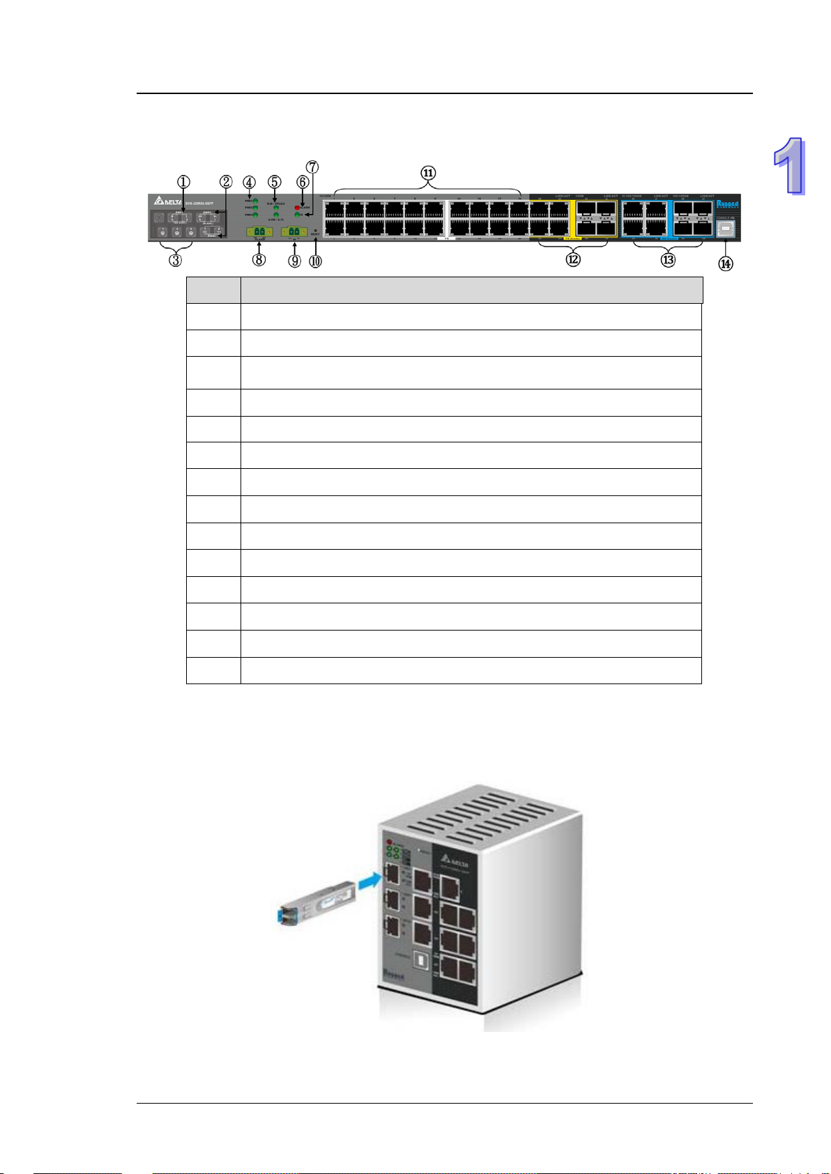
1.1.4 Front Panel Ports and LEDs
No Description
1 AC power input.
2 Redundant DC power input
3 Grounding Screw
4 Power LED
5 ONE RING / ONE CHAIN / ONE COUPLING LED
6 Alarm LED
7 DI LED
Chapter 1 Introduction
8 Relay alarm port
9 Digital Input
10 Reset button
11 Fast Ethernet ports
12 Fast Ethernet Combo ports
13 Gigabit Ethernet Combo ports
14 USB CONSOLE port
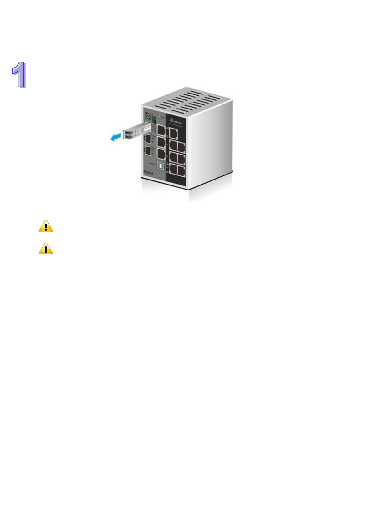
1.2 SFP Module Installation
Insert:
Insert SFP Module into the SFP combo port.
1-3
Page 12
DVS Managed Industrial Rack Mount Ethernet Switc hes User Manual
Note:
compatible with Delta SFP module.
Note:
loss values once the link is established to identify any potential performance issues.
Remove:
Pull the tab on the module, and then pull out it.
Delta has LCP-155 and LCP-1250 series SFP module. DVS switch can promise 100%
The actual link distance of a particular fiber optic link given the optical budget, the number
of connectors and splices, and cabling quantity. Please measure and verify the actual link
1.3 Package Checklist
Delta DVS series Managed Rack Mount Ethernet Switch
Protective Caps for unused RJ45 ports and fiber ports (inserted to the switch)
USB Type A to Type B console cable
User manual and software CD
Instruction Sheet
Rack bracket*4
M4 screw*20
M5 screws*6
T4 screw*6 and anchor screw*6
Rubber feet*4
Rubber Plug*16(Inserted to the switch)
1.4 MTBF (Mean Time Between Failures)
More than 1,100,000 hours.
1-4
Page 13

MEMO
Chapter 1 Introduction
1-5
Page 14

Chapter 2 User Interface Introd u ction
Table of Contents
2.1 USB Console Configuration ................................................................. 2-2
2.2 Telnet Console Configuration .............................................................. 2-5
2.3 Web Browser Configuration ................................................................ 2-6
2-1
Page 15
DVS Managed Industrial Rack mount Ethernet Switch User Manual
Note:
terminal software to use it.
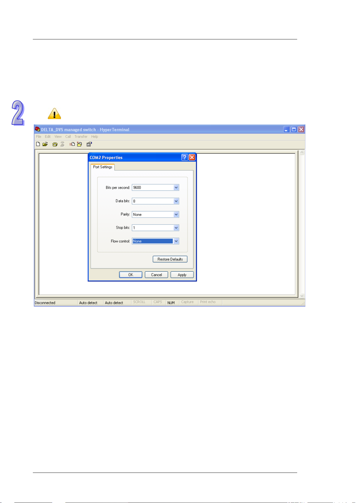
2.1 USB Console Configuration
A Delta switch support s configur ation using the CLI interface, availab le on the USB port with the baud rate 9600.
You can use the terminal sof tware to connect to a Delta switch. The inactivity timeout value on a serial port
connection can be configured between 0 and 160 minutes. (Value 0: disable the timeout.)
1. Open the terminal software, and sele ct an appropriate COM port for Console Connection, 9600 for Baud
Rate, 8 for Data Bits, None for Parity, and 1 for Stop Bits, None for Flow Control.
The Windows 7 system does not support Hyper Terminal. If you need it, you can download the
2-2
Page 16
Chapter 2 User Interface Introduction
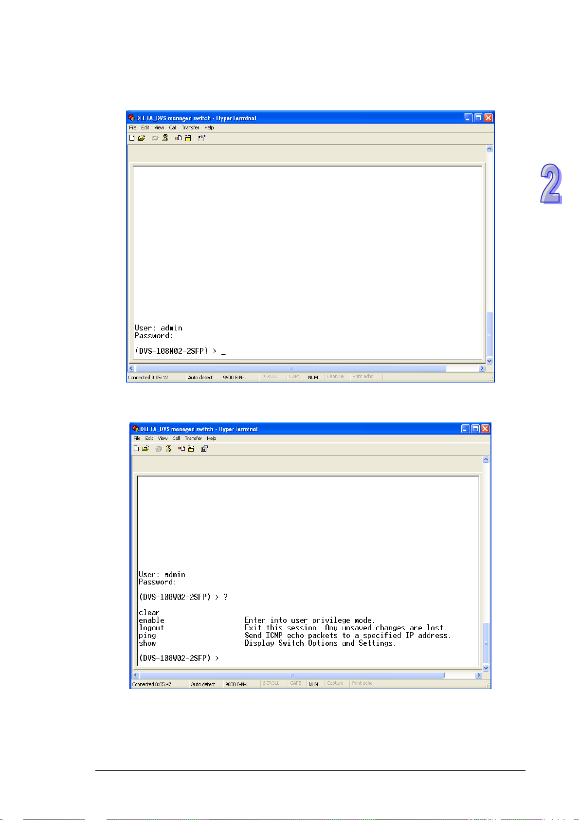
2. The user name and the password are the same as Web Browser. The default user name is “admin”, and
the password is blank.
You can use “?” to list the commands.
2-3
Page 17

DVS Managed Industrial Rack mount Ethernet Switch User Manual
Note:
USB driver. You can find the driver in the CD package.
Example 1:
There is a DHCP server in your environment, and the Delta switch can get an IP address from the DHCP
server. I f y o u d on’t want to check the IP address from the DHCP serv er, then you can use the USB console
cable to login to the Delta switch. Using the “show network” command can display the IP address
information of the Delta switch.
Example 2:
If you want to change the network configuration protocol from DHCP mode to static mode, using CLI
commands to change the protocol and setting a static IP address and a subnet mask.
(DVS-108W02-2SFP) > enable
(DVS-108W02-2SFP) # configure terminal
(DVS-108W02-2SFP) (config)# interface vlanmgmt
(DVS-108W02-2SFP) (config-if)# no ip address
(DVS-108W02-2SFP) (config-if)# ip address 10.10.10.1 255.255.255.0
(DVS-108W02-2SFP) (config-if)# exit
(DVS-108W02-2SFP) (config)# exit
(DVS-108W02-2SFP) # sa v e
Building configuration ...
[OK]
(DVS-108W02-2SFP) #
Before you use the USB console configuration, please make sure that you have ins t alled the
2-4
Page 18

Chapter 2 User Interface Introduction
2.2 Telnet Console Configuration
A Delta switch supports the telnet server function; it can be globally enabled or disabled. The user can use all
CLI commands over a telnet session. The maximum number of inbound telnet sessions allowed on the switch
can be configured to 0-5. The inactivity timeout value for the incoming Telnet sessions for the switch can be
configured to 1-160 minutes. The login authentication supports the local user method or the remote user
method which is configured. When the login authenticatio n is the remote user method, it supports RADIUS and
TACACS+.
1. Open a Command Prompt window and input “telnet 192.168.1.5” to login to a De lt a switch.
2. After entering a user name and a password, you can use the CLI command to control the switch.
Note:
The default user name is “admin” and the password is blank.
2-5
Page 19

DVS Managed Industrial Rack mount Ethernet Switch User Manual
2.3 Web Browser Configuration
The Delta switch supports a friendly GUI for administrators to configure the switch. Admin user can monitor the
port status of a Delta switch, and configure the settings of each function via the web interface.
The switch provides an admin user of high access level to creat e lower access level of a normal user
1. Open a web browser and connect to the default IP address 192.168.1.5. Enter a user nam e and a
password. (The defa ult user name is “adm in” and the password is blank.)
You can also change the language into English or Simplified Chinese via the drop-down list on the upper
right.
Note: The default user name “admin” is in the lowercase not uppercase.
2. When an admin user logging in, the menu tree will show up the complete functions.You can see as below:
2-6
Page 20

Chapter 2 User Interface Introduction
When a normal user loggin in, the menu tree will show up the part of functions.You can see as below:
3. The port status an d the LED status on the sw itch ca n be mon itor ed in th e top f rame. The status of the Delta
switch in the top frame displays the real status with the physical switch synchronously.
2-7
Page 21

DVS Managed Industrial Rack mount Ethernet Switch User Manual
MEMO
2-8
Page 22

Chapter 3 Featured Functions
Table of Contents
3.1 Basic Setting .......................................................................................... 3-5
3.1.1 System Information ...................................................................... 3-5
3.1.2 Network Interface .......................................................................... 3-6
3.1.2.1 IPv4 Network Configuration ................................................. 3-6
3.1.2.2 IPv6 Network Configuration ................................................. 3-7
3.1.2.3 IPv6 Network Neighbor ......................................................... 3-8
3.1.3 Port Settings ................................................................................... 3-9
3.1.3.1 Port Settings ............................................................................ 3-9
3.1.3.2 LAG Settings ...........................................................................3-10
3.1.4 Time ................................................................................................ 3-11
3.1.4.1 SNTP Scalars Configuration ................................................. 3-11
3.1.4.2 SNTP Unicast Server Configuration ....................................3-12
3.1.5 DHCP/BOOTP Settings .................................................................3-13
3.1.5.1 DHCP Server ...........................................................................3-13
3.1.5.2 DHCP Relay .............................................................................3-17
3.1.5.3 DHCP L2 Relay .......................................................................3-19
3.1.6 DNS .................................................................................................3-23
3.1.6.1 DNS Configuration .................................................................3-23
3.1.6.2 Host Configuration .................................................................3-24
3.1.7 System File Update ......................................................................3-24
3.1.7.1 Download File .........................................................................3-24
3.1.7.2 Upload Fi le ..............................................................................3-26
3.1.8 Management Acce ss .....................................................................3-28
3.1.8.1 HTTP Configuration ................................................................3-28
3.1.8.2 HTTPS ......................................................................................3-28
3.1.8.3 SSH Configuration .................................................................3-31
3.1.8.4 Telnet Configuration ..............................................................3-32
3.1.8.5 Console Port............................................................................3-33
3.1.9 Loopback-Detection ......................................................................3-33
3.1.9.1 Global Configuration .............................................................3-33
3.1.9.2 Port Configuration .................................................................3-34
3.1.10 EtherNet/IP ................................................................................3-35
3.2 SNMP Manager .....................................................................................3-35
3.2.1 SNMP v1/v2c .................................................................................3-35
3.2.1.1 Community Configuration ....................................................3-35
3.2.1.2 Trap Configuration .................................................................3-36
3.2.1.3 Trap Flags ................................................................................3-37
3.2.2 SNMP v3 .........................................................................................3-38
3.2.2.1 User Configuration.................................................................3-38
3.3 Network Redundancy ..........................................................................3-40
3.3.1 STP ..................................................................................................3-40
3.3.1.1 STP Configuration ..................................................................3-44
3.3.1.2 CST Configuration..................................................................3-45
3-1
Page 23

3.3.1.3 CST Port Configura tion ......................................................... 3-48
3.3.1.4 CST Port Status ..................................................................... 3-50
3.3.1.5 MST Configuration ................................................................. 3-52
3.3.1.6 MST Port Status ..................................................................... 3-53
3.3.1.7 STP Statistics ......................................................................... 3-55
3.3.2 Redundancy ................................................................................... 3-57
3.3.2.1 ONE RING Configuration ...................................................... 3-57
3.3.2.2 ONE CHAIN Configuration .................................................... 3-57
3.3.2.3 ONE COUPLING Configuration ............................................ 3-58
3.3.2.4 Redundancy Cruiser .............................................................. 3-59
3.4 Virtual LANs .......................................................................................... 3-61
3.4.1 VLAN Mode Configuration ........................................................... 3-62
3.4.2 VLAN Configuration ...................................................................... 3-62
3.4.3 VLAN Membership ........................................................................ 3-63
3.4.4 VLAN Status .................................................................................. 3-64
3.4.5 Port PVID Configuration .............................................................. 3-64
3.4.6 GVRP Configuration ...................................................................... 3-65
3.4.7 Double VLAN Configuration ........................................................ 3-66
3.4.8 MAC Based VLAN .......................................................................... 3-68
3.4.9 IP Subnet Based VLAN ................................................................ 3-68
3.5 Multicast Filtering ................................................................................ 3-69
3.5.1 IGMP Snooping Configuration .................................................... 3-70
3.5.2 IGMP VLAN Configuration ........................................................... 3-71
3.5.3 IGMP Snooping Multicast Forwarding Table ............................. 3-72
3.5.4 Multicast MAC Address Configuration ....................................... 3-72
3.5.5 GMRP Configuration ..................................................................... 3-73
3.5.6 Multicast Forwarding Table ......................................................... 3-74
3.6 Traffic Prioritization ............................................................................. 3-74
3.6.1 QoS ................................................................................................. 3-75
3.6.1.1 QoS Setting ............................................................................ 3-75
3.6.1.2 CoS Queue Mapping ............................................................. 3-76
3.6.1.3 DSCP Queue Mapping ........................................................... 3-76
3.7 Traffic Control ....................................................................................... 3-78
3.7.1 Port Protected ............................................................................... 3-78
3.7.2 Port Isolation Configuration ........................................................ 3-78
3.8 Port Bandwidth ..................................................................................... 3-79
3.8.1 Storm Control................................................................................ 3-79
3.8.1.1 Storm Control Setting .......................................................... 3-79
3.8.1.2 Rate Limiting .......................................................................... 3-81
3.9 Port Trunking ........................................................................................ 3-82
3.9.1 LAG .................................................................................................. 3-82
3.9.1.1 LAG Membership ................................................................... 3-82
3.9.1.2 LAG Information .................................................................... 3-83
3.10 Access Control List ........................................................................... 3-84
3.10.1 MAC ACL ..................................................................................... 3-84
3.10.1.1 MAC Rules ........................................................................... 3-85
3-2
Page 24

3.10.1.2 MAC Binding Configuration...............................................3-87
3.10.2 Binding Table ..............................................................................3-88
3.11 Security Settings ..............................................................................3-88
3.11.1 Security .......................................................................................3-88
3.11.1.1 Port Security .......................................................................3-88
3.11.1.2 IP Source .............................................................................3-90
3.11.1.3 802.1X ..................................................................................3-91
3.11.2 Management Security ..............................................................3-96
3.11.2.1 Local Users Management ..................................................3-96
3.11.2.2 RADIUS Server Config ......................................................3-97
3.11.2.3 RADIUS Statistics ...............................................................3-98
3.11.2.4 TACACS+ Server ................................................................3-99
3.11.2.5 TACACS+ AS .......................................................................3-99
3.11.2.6 Login Authentication ........................................................3-100
3.11.2.7 Login User Sessi ons .........................................................3-100
3.11.3 Denial of Service .....................................................................3-101
3.12 Monitoring Settings ........................................................................3-102
3.12.1 MAC Address Table ..................................................................3-102
3.12.2 SFP DDM (Only for SFP Module) ..........................................3-104
3.12.3 System CPU Status .................................................................3-104
3.12.4 Interface Statistics ..................................................................3-105
3.12.5 ARP Configure ..........................................................................3-105
3.12.5.1 Basic ...................................................................................3-105
3.12.6 RMON .........................................................................................3-106
3.12.6.1 Basic Settings ...................................................................3-106
3.12.6.2 Alarms ................................................................................3-106
3.12.6.3 Events ................................................................................3-108
3.12.6.4 Event Log ...........................................................................3-108
3.12.6.5 History ................................................................................3-109
3.12.6.6 RMON Ethernet Statistics ...............................................3-109
3.12.6.7 Ethernet History Statistics ............................................. 3-111
3.12.7 SYSLOG ..................................................................................... 3-113
3.12.7.1 Show Logs ......................................................................... 3-113
3.12.7.2 Logs Configuration ........................................................... 3-113
3.12.7.3 Syslog Fwd Table .............................................................. 3-115
3.12.7.4 Syslog Email Configuration ............................................ 3-116
3.12.7.5 Syslog Email Alarm Table ............................................... 3-117
3.13 Diagnostic Settings ........................................................................ 3-119
3.13.1 LLDP ........................................................................................... 3-119
3.13.1.1 LLDP Basic Settings ......................................................... 3-119
3.13.1.2 LLDP Interface Configuration .........................................3-120
3.13.1.3 LLDP TLV Options .............................................................3-121
3.13.1.4 LLDP Local Information ...................................................3-121
3.13.1.5 LLDP Neighbor Information ............................................3-123
3.13.1.6 LLDP Traffic .......................................................................3-125
3.13.1.7 LLDP-MED Global Configuration ....................................3-126
3-3
Page 25

3.13.1.8 LLDP-MED Interface Configuration ............................... 3-126
3.13.2 Port Mirroring ........................................................................... 3-127
3.13.2.1 Multiple Port Mirroring .................................................... 3-127
3.13.2.2 Cable Diagnostics ............................................................ 3-129
3.14 Auto Warning .................................................................................. 3-130
3.14.1 Relay Alarm .............................................................................. 3-130
3.14.1.1 Relay Alarm Setting ........................................................ 3-130
3.14.1.2 Relay Alarm Table ............................................................ 3-132
3.15 Dual Image...................................................................................... 3-133
3.15.1 Copy .......................................................................................... 3-133
3.15.2 Configuration ........................................................................... 3-133
3.16 Save Config ..................................................................................... 3-134
3.16.1 Save Configuration ................................................................. 3-134
3.16.2 Auto-Save Configuration ....................................................... 3-134
3.16.3 Configuration Copy ................................................................. 3-134
3.16.4 Restore ...................................................................................... 3-135
3.16.5 Erase ......................................................................................... 3-135
3.17 Reset ................................................................................................ 3-135
3.17.1 Device Reboot.......................................................................... 3-135
3.17.2 Factory Default Settings ........................................................ 3-136
3.18 Troubleshooting .............................................................................. 3-136
3.18.1 Ping IPv4 .................................................................................. 3-136
3.18.2 Ping IPv6 .................................................................................. 3-137
3.18.3 Traceroute IPv4 ....................................................................... 3-138
3.18.4 Traceroute IPv6 ....................................................................... 3-138
3.19 Logout .............................................................................................. 3-139
3-4
Page 26

Chapter 3 Featured Functions
Description
Factory default
System Name
Input the system name of the switch.
None
System Location
Input the system location of the switch.
None
System Contact
Input the system contact of the switch.
None
Serial Number
The serial number of the switch.
Fixed
System Object ID
The based object ID for the Management Information Base (MIB) of the switch.
Fixed
Date & Time
The current date and time.
None
System Up Time
The time of hours, minutes, and seconds since the switch was last started.
None
MAC Address
The MAC address of the switch.
Fixed
3.1 Basic Setting
The basic setting group includes the most common settings, and an administrator can maintain the control of
the Delta switch in this group.
IMPORTANT:
Make sure that you save the configuration in the Sav e Co nfigur atio n
page after you have applied the configuration changes. (Save
Config
then the configuration will be cleared after the switch is rebooted.
Save Configuration) If you do not save the configuration,
3.1.1 System Information
System Information includes the basic switch sta tus items and the version .It also di splayed in t he bann er of the
GUI. These informations can help the administrator identify the switch in the network.
Switch Status
3-5
Page 27
DVS Managed Industrial Rack Mount Ethernet Switch User Manual
Description
Factory default
Model Name
The model name of the switch.
Model Name
Boot Version
The boot version of the switch.
Boot Version
Software Version
The software version of the switch.
Software Version
Versions
3.1.2 Network Interface
The network interface on th e n etw ork device is a logical interface. Each netw or k dev i ce mus t hav e one or m ore
interfaces to connect with other network devices. But the configuration of the network interface does not affect
the traffic which is forwarded.
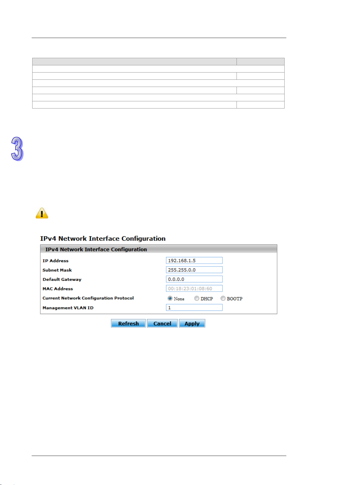
3.1.2.1 IPv4 Network Configuration
You can configure a static IP address, a subnet mask and a default gateway for the switch. Or you can enable
DHCP mode or BOOTP mode for receiving a dynam ic IP a ddress, a subnet mask and a def ault gateway. If you
enable DHCP mode or BOOTP mode, but there is no DHCP or BOOTP server in the network, the default link
local IP address will be 169.254.100.100.
Note:
The default Current Network Configuration Protocol is None. And the default IP address is
192.168.1.5.
3-6
Page 28
Chapter 3 Featured Functions
Description
Factory default
IP Address
login again, and making sure the URL is the latest IP address.
Subnet Mask
Input the IP subnet mask of the IPv4 network interface.
255.255.0..
Default Gateway
Input the default gateway of the IPv4 network interface.
0.0.0.0.
MAC Address
This field displays the MAC address of the switch.
MAC address
Current Network Configuration Protocol
Select one item to specify how the switch gets its IP information:
(BOOTP) server on the network.
Management VLAN ID
Input the management VLAN ID in the range from 1 to 4094.
1
Description
Factory default
Admin Mode
Enable: IPv4 / IPv6 mode. Support both IPv4 and IPv6.
IPv6 Gateway
Input the IPv6 address of the IPv6 gateway.
None
IPv4 Network Interface Configuration
Input the IP address of the IPv4 network interface.
Note:
After you change the IP ad dres s and cli cking Apply, we suggest you to
None: Specify the static IP address information.
DHCP: The IP information of the switch is assigned by a Dynamic Host
Configuration Protocol (DHCP) server on the network.
BOOTP: The IP information of the switch is assigned by a Bootstrap Protocol
192.168.1.5
None
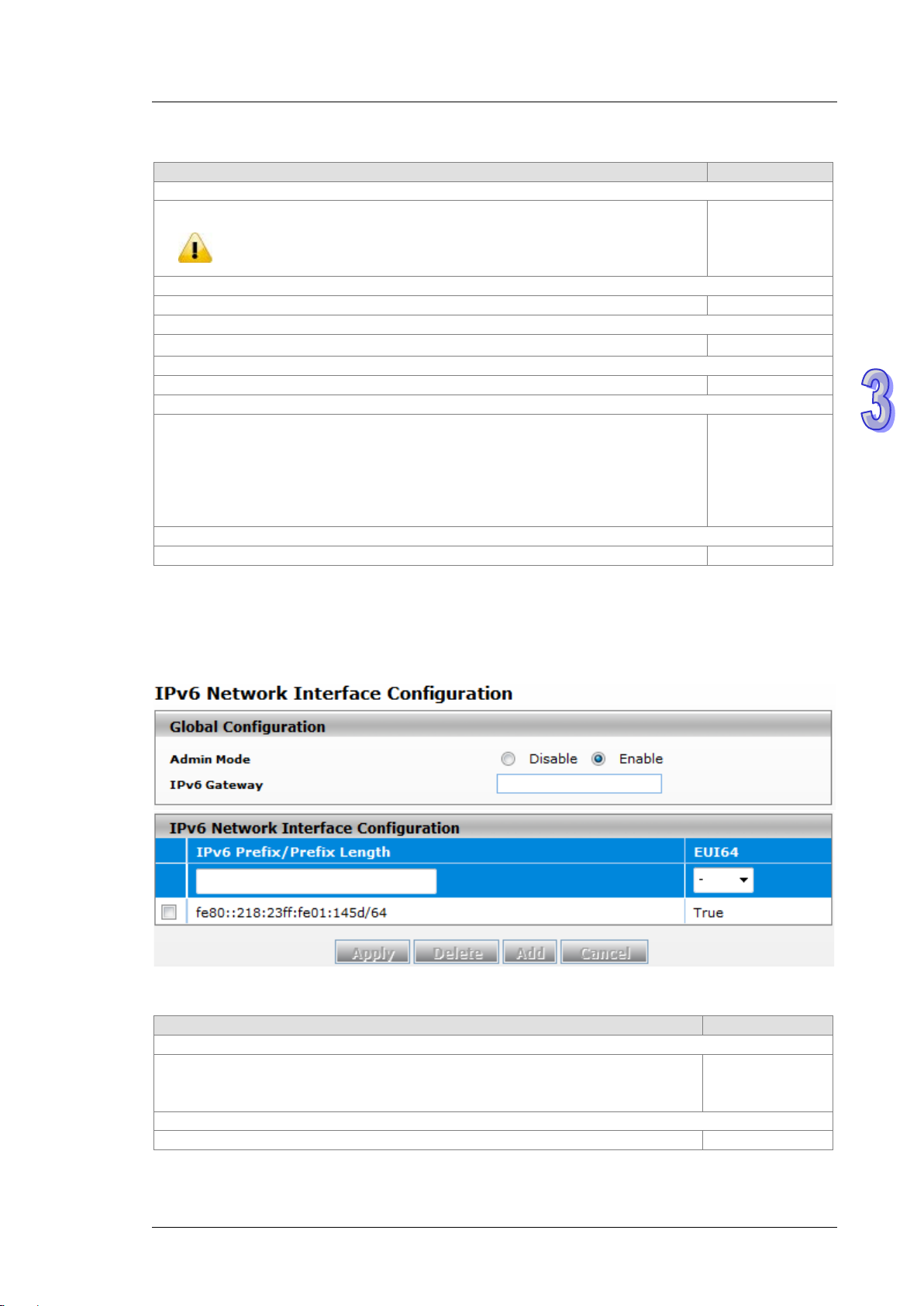
3.1.2.2 IPv6 Network Configuration
If you need to configure a global IPv6 address, please follow the standard format: “IPv6 Prefix/Prefix Length”.
Example: “1001:2002:3003::7007:8008/64”
Global Configuration
Specify the IPv6 administrative status of the network interface by selecting one item:
Disable: IPv4 only mode. Only support IPv4, not support IPv6.
Enable
3-7
Page 29

DVS Managed Industrial Rack Mount Ethernet Switch User Manual
Description
Factory default
IPv6 Prefix / Prefix Length
Enter the IPv6 address followed by a slash and then the prefix length of the network
interface.
EUI64
Specify whether the IPv6 address is in the 64-bit extended unique identifier (EUI-64)
False: The IPv6 address is not in the EUI-64 format.
DHCP server.
Description
Factory default
IPv6 Address
The IPv6 address of the neighbor.
None
MAC Address
The MAC address of the neighbor.
None
Neighbor State
The status of the neighbor:
Unknown: The status of the neighbor is unknown.
IPv6 Network Interface Configuration
IPv6 address
format:
True: The IPv6 address is in the EUI-64 format.
Note:
An IPv6 address in the EUI-64 format is an automatically self-assigned unique 64-bit IPv6 interface
identifier. You do not need to manually configure such an IPv6 address, and it is not assigned by a
3.1.2.3 IPv6 Net work Neighbor
The IPv6 network interface neighbor table can display the neighbor IPv6 address.
IPv6 Network Interface Neighbor Table
None
Static: The neighbor has a static IP address.
Reachable: The neighbor was reached very recently (that is, within a
period of tens of seconds).
Incomplete: The address resolution for the neighbor is in progress, but the
link-layer address of the neighbor has not yet been determined.
Stale: The neighbor ca n no lo nger b e rea che d. Until the traffic is sent to the
neighbor, no atte mpt is made to ver ify it if it can be reached again.
Delay: The neighbor can no longer be reached. The traffic was recently
sent to the neighbor, but neighbor solicitation probes are delayed because
the confirmation that the neighbor can be reached might be received.
Probe: The neighbor can no longer be reached. Unicast neighbor
solicitation probes are sent to verify whether the neighbor can be reached
again.
3-8
None
Page 30
Chapter 3 Featured Functions
Description
Factory default
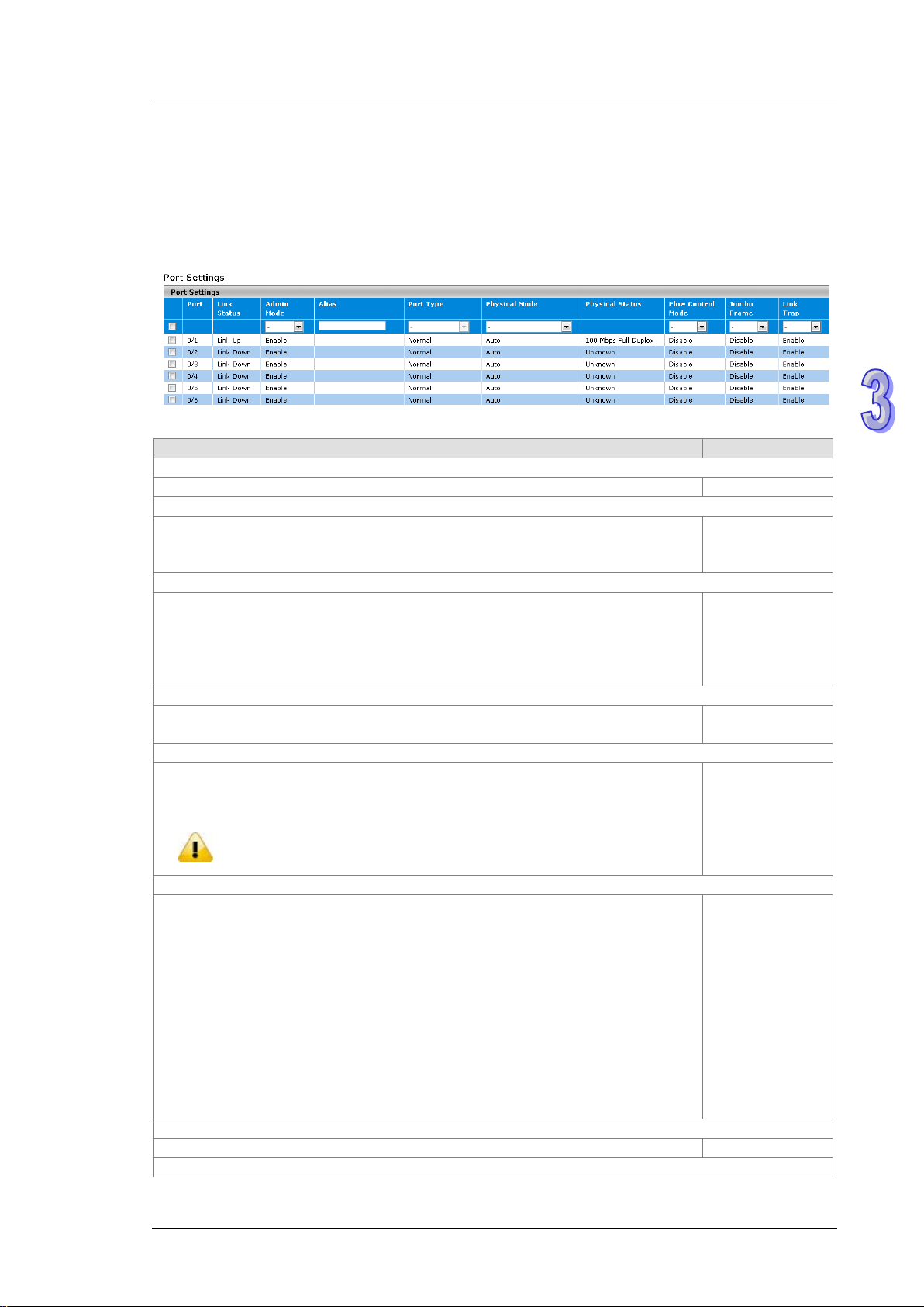
Port
This field displays the interface number.
interface number
Link Status
This field displays the connection of the interface.
Link Down: No network dev ice is conne ctin g to the inter fac e .
Admin Mode
The administrative state of the interface:
the interface.
Alias
Specify an alias for the port to help administrators differentiate between different ports.
For example: Head port.
Port Type
This field displays whether the interface is a member of a port channel:
Note:
LAG configuration could be configured in Port Trunk.
Physical Mode
Specify the speed capability of each interface:
duplex mode.
Physical Status
This field displays the actual port speed and the duplex mode.
None
Flow Control Mode
3.1.3 Port Settings
You can configure the basic port settings and LAG settings of the Delta switch in the Port Settings group.
3.1.3.1 Port Settings
You can configure and monitor the port status on this page.
Port Settings
Link Up: There is a network device connecting to the interface.
Enable: The interface is switched on and the network device can connect to the
interface.
Disable: The interfa ce is sw itc hed off and the network device can not connect to
Trunk Member: The interface is a member of a link aggregation group.
Normal: The interface is not a member of a link aggregation group (port channel).
If you add ports in the lag, the port type will show “Trunk Member”. The
Auto: The duplex mode and the speed of the interface are set by the
auto-negotiation process. The interface can support the maximum capability: Full
duplex and 1 Gbps or 100Mbps.
10 Mbps Half Duplex: Indicates that the interface works at 10 Mbps in the half
duplex mode.
10 Mbps Full Duplex: Indicates that the interface works at 10 Mbps in the full
duplex mode.
100 Mbps Half Duplex: Indicates that the interface works at 100 Mbps in the half
duplex mode.
100 Mbps Full Dup lex: Indicates that the interface works at 100 Mbps in the full
Link down
Enable
None
Normal
Auto
3-9
Page 31

DVS Managed Industrial Rack Mount Ethernet Switch User Manual
Description
Factory default
not send pause packets.
Jumbo Frame
Disable: The jumbo frame is disabled.
Link Trap
Specify whether to send a trap when the interface lin k st atu s chan ges :
Disable: When the link status changes, the switch does not send a trap.
Description
Factory default
Port
This field shows the interface number.
interface number
Link Status
This filed shows the connection of the interface.
Link Down: The interface is not connected to another device.
Admin Mode
Specify the administrative state of the interface:
device.
Jumbo Frame
The filed displays whether the jumbo frame is enabled for the port.
Disable: The jumbo frame is disabled.
Link Trap
Specify whether the switch sends a trap when the interface link status changes:
Disable: When the link status changes, the switch does not send a trap.
This field displays whether the flow control is enabled for the port:
Enable: The flow control is enabled. If the port buffers bec o me full, the sw itch
sends pause packets.
Disable: T he flow control is disabled. If the port buffers become full, the switch does
The field displays whether the jumbo frame is enabled for the port.
Enable: The jumbo frame is enabled. The switch supports a fixed jumbo frame size
- 9000 bytes payload (9218 bytes frame) size.
Disable
Disable
Enable: When the link stat us c hange s, the switch sends a trap. This is the default
setting.
3.1.3.2 LAG Settings
You can configure the LAG settings and monitor the LAG status on this page.
LAG Settings
Enable
Link Up: The interface is connected to another device.
Enable: The interface is switched on and ca n be conne cted t o another devic e.
Disable: The interface is switched o f f and can not be connected to another
Enable: The jumbo frame is enabled. The switch supports a fixed jumbo
frame size - 9000 byte payload (9018 byte frame) size.
Enable: When the link status changes, the switch sends a trap. This is the
default setting.
3-10
Link Down
Enable
Disable
Enable
Page 32

Chapter 3 Featured Functions
Description
Factory default
SNTP Client Status
Specify whether the switch works as an SNTP client, and the switch will send an NTP
Disable: The switch does not work as an SNTP client.
SNTP Server Status
Specify whether the switch works as an SNTP server.
Disable: The switch does not work as an SNTP server.
Date
The date parameter format is DD/MM/YYYY.
is enabled, the field is grayed out.
Time
The time parameter format is HH:MM :S S.
client is enabled, the field is grayed out.
Time Zone
The time zone setting format HH:MM is preceded by a plus (+) or minus (-). For
Mean T ime) to the local time.
DST StarTime
Enter the daylight saving t ime (DS T) st art time. Specify the date and time in the following
For example, if DST starts on the first Saturday in May at 03:00 AM, enter the following
3.1.4 Time
The Delta managed sw itch su pports SNTP (Simple Network Time Protocol). It can work as an SNTP client to
get time from an SNTP or NTP server, and it also can work as an SNT P server to provi de ti me serv ice an d send
a time reply to a client.
3.1.4.1 SNTP Scalars Configuration
SNTP Scalars Configuration lets a user configure the time of the switch which can be gotten from the SNTP
server. And it also can be configured manually.
SNTP Scalars Configuration
request to the server which the user specify on the SNTP Unicast Server Configuration
page.
Enable: The switch works as an SNTP client.
Enable: The switch works as an SNTP server.
When an SNTP client is disabled, you can manually set the date. When an SNTP client
When an SNTP client is disabled, you can mpinganually set the time. When an SNTP
Disable
Disable
DD/MM/YYYY
HH:MM:SS
example, for Taipei, enter +08:00. An d it allow s the conversion from GMT (Greenwich
format:
Week of the month-day of the week-month-HH:MM.
+00:00
None
3-11
Page 33

DVS Managed Industrial Rack Mount Ethernet Switch User Manual
Description
Factory default
format: First-Sat-May-03:00.
DST EndTime
Enter the daylight saving time (DST) end time. Specify the date and time in the following
following format: Second-Mon-Dec-04:00.
Note:
saved the changes
Description
Factory default
Forward Address Ty pe
Specify a type of SNTP server IP address:
DNS: Use FQDN to recognize an SNTP server.
Unicast Server IP Address
Enter the server IPv4, IPv6 address or host name (FQDN). (Depend on the type you
select in the Forward Address Ty pe field.)
Unicast Server Type
Specify a type of server by selecting Primary or Secondary from the drop-down list.
None
Last Updated
This field displays the last time the SNTP unicast server updated its time information.
None
Tx Requests
This field displays the number of SNTP transmit requests made by the switch since it
was last rebooted.
that you add the SNTP unicast server for the Delta switch to synchronize the time.
It can make sure that the time on the Delta switch is accurate.
format:
Week of the month-day of the week-month-HH:MM.
For example, if DST ends on the second Monday in December at 04:00 AM, enter the
1. After you have clicked Apply, the date and time are applied and the fields revert to their default
setting of DD/MM/YYYY and HH:MM:SS.
2. The manual date and time setting will be lost after the switch is rebooted, even if you have
3.1.4.2 SNTP Un ica st Se rver Configuration
If you want to specify a known SNTP server, you can enter the IP address or DNS on this page.
None
SNTP Unicast Server Configuration
IPv4: Use an IPv4 address to recognize an SNTP server. This is the default
setting.
IPv6: Use an IPv6 address to recognize an SNTP server.
Note:
We recommend
IPv4
None
None
3-12
Page 34

Chapter 3 Featured Functions
Description
Factory default
Admin Mode
Specify the status of the DHCP server on the switch:
Enable: The DHCP server is enabled.
Next Server
Specify the boot server host name.
0.0.0.0
Boot File
Specify the boot file name.
None
Network
Enter the network for the DHCP pool.
None
Subnet Mask
Enter the IP subnet mask for the DHCP pool.
3.1.5 DHCP/BOOTP Settings
The Delta switch can functio n as a DHCP server, DHCP relay and DHCP L2 relay. If ther e i s n o DH CP server in
your network, then you can enable a DHCP server function on the Delta switch. If there is a DHCP server in
your network, then you c an co nfigur e the Delt a switch as a DHCP relay. If there is already a DHCP server and a
DHCP relay in your network, or there are L2 devices between DHCP clients and relay agents, then you can
configure the Delta switch as a DHCP L2 relay in this network.
3.1.5.1 DHCP Server
If the DHCP server i s enab led on the switch, it can assign an IP address which is in the same network as the
switch to the client.The Delta switch also supports the M AC Based DHCP Configuration and the Port Based
DHCP Configuration.
DHCP Server Configuration
You can enable or disable the DHCP server function and configure the DHCP configuration on this page.
DHCP Server Configuration
Disable: The DH CP server is disabled. When you want to en able the D HC P
relay function, please select this setting.
Disable
None
3-13
Page 35

DVS Managed Industrial Rack Mount Ethernet Switch User Manual
Description
Factory default
Lease Time Type
Infinite: The leased IP address does not expire.
Lease Time
Time fields.
Default Router
DHCP offer packet.
DNS Server
DHCP offer packet.
Domain Name
packet.
Description
Factory default
IP Range From
DHCP server pool.
IP Range To
DHCP server pool.
Method
None
Manual: The entry is created by a user.
Description
Factory default
Option Code
Options and BOOTP Vendor Extensions.)
Option Type
IP Addr ess: Enter an IP address or a subnet mask in the Option Value field.
Specify a type of lease time:
Specified Duration: The leased IP address has a specific duration. You
need to specify the duration in the Lease Time fields.
If you select S pecif ied Dura tion from the Lease Time Type in the drop-down list,
specify the duration by entering the days, hours, and minutes in the Lease
None
None
Specify the default gateway IP address. The information will be included in the
Specify the DNS server IP address. The information will be included in the
Specify the domain name. The information will be included in the DHCP offer
Excluded Addresses
Enter the start IP address of the exclusion IP range which you created in the
Enter the end IP address of the exclusion IP range which you created in the
It indicates that the excluded addr es s is creat ed by a DHCP server or a user.
There are two values:
Auto: The entry is created by a DHCP server.
DHCP Server Pool Option Configuration
DHCP messages contain many option fields. These options hav e much contr ol infor mat ion and many
configuration parameters.
None
None
None
None
None
None
DHCP Server Pool Option Configuration
Enter the option code. For example, the option code 3 is a router, 6 is a domain
name server. (If you need more information, please refer to RFC2132, DHCP
Specify the option type:
ASCII: Enter an ASCII value in the Option Value field.
Hex: Enter a hexadecimal value in the Option Value field.
3-14
None
None
Page 36

Chapter 3 Featured Functions
Description
Factory default
Option Value
Enter the value that corresponds to the option type you select.
None
Description
Factory default
IP Address
The IP address of the DHCP client.
None
Hardware Type
MAC address.
Hardware Address
This field displays the MAC address or the string identifier of the DHCP client.
None
Expire Time
The expiration time of the DHCP client.
None
Note:
time.
default
Admin Mode
be enabled the DHCP server mode first.
DHCP Server Binding Table
If the DHCP server function is activated, you can see the DHCP client’s information which is get the IP
address from the DHCP server on this page.
DHCP Server Binding Table
This field displays a type of hardware address of the client.
Client ID: If the client uses DHCP option 61 to specify itself, the hardware
type is the client ID, and the hardware address is the string identifier.
None
Ethernet: The hardware type i s Ether net, and t he hardware address is an
MAC Based DHCP Configuration
MAC Based DHCP Configuration supports the administrator assigned the specific IP address to the MAC
address in the list.
MAC Based DHCP Mode and Port Based DHCP Mode can’t enable and work at the same
MAC Based DHCP Mode
Description Factory
Specify the status of the MAC Based DHCP on the sw itch.
Disable: The MAC Based DHCP Configuration is disabled.
Enable: The MAC Based DHCP Configuration is enabled.
Note:
If you need to enable t he admin mode of MAC Base d D HC P Mode, it must
Disable
3-15
Page 37

DVS Managed Industrial Rack Mount Ethernet Switch User Manual
Description
Factory default
Pool ID
It’s the DHCP Pool number.
fixed
Hardware Type
MAC address.
Hardware Address
This field displays the MAC address or the string identifier.
None
IP Address
should be included in the Excluded Address of DHCP Server Configuration.
Description
Factory
default
Admin Mode
Specify the status of the Port B ased DHCP on t he sw itch.
Note:
If you need to enabl e the admin mode of M A C Base d D HC P Mode, it must
be enabled the DHCP server mode first.
MAC Based DHCP Binding Configuration
This field displays a type of hardware address of the client.
Client ID: The ty pe of the H W address.If the client uses DHCP option 61 to
specify itself, the hardw are typ e is the client ID, a nd the har d ware address is
the string identifier.
Ethernet: The type of the HW address, and the hardware addres s is an
None
It’s the static IP address which assigned to the specified HW Address.And it
None
Port Based DHCP Configuration
Port Based DHCP Configuration supports the administrator assigned the specific IP address for the port
number in the list.
Note:
MAC Based DHCP Mode and Port Based DHCP Mode can’t enable and w or k at t he sa me t ime.
Port Based DHCP Mode
Disable: The Port Based DHCP Mode is disabled.
Enable: The Port Based DHCP Mode is enabled.
Disable
3-16
Page 38

Port Based DHCP Binding Configuration
Description
Factory default
Pool ID
It’s the DHCP Pool number.
1
Interface
IP Address
included in the Excluded Address of DHCP Server Configuration.
Note:
binding to assign IP address to the client.
Description
Factory default
IP Address
Configuration or Port Based Binding Configuration.
Hardware Type
MAC address.
Hardware Address
This field displays the MAC address or the string identifier.
None
Chapter 3 Featured Functions
The interface number .You can specify the interface which will assign the
specific IP address when the DHCP client is connect to the specific interface.
The static IP address w hich as signed to t he spe cified interface.And it should be
RARP Bindings Configuration
The RARP Bindings Configuration supports to use RARP to acquire IP for device without DHCP client
function.
Please remember to enable the MAC Based DHCP Binding Configuration or Port Based
Binding Configuration before you use this function, otherwise the RARP will not use the static
RARP Binding Configuration
None
None
It’s the static IP which acquired from the MAC Based DHCP Binding
This field displays a type of hardware address of the client.
Client ID: The ty pe of the H W address.If the client uses DHCP option 61 to
specify itself, the hardw are typ e is the client ID, a nd the har d ware address is
the string identifier.
Ethernet: The type of the HW address, and the hardware address is an
None
None
3.1.5.2 DHCP Relay
A DHCP Relay can make broadcast messages to be sent over routers. And a DHCP relay can receive a DHCP
broadcast request pa cket an d f orw ard it to a specified server. The operating theory is show n in the fig ure below.
3-17
Page 39

DVS Managed Industrial Rack Mount Ethernet Switch User Manual
Notice:
Description
Factory default
Admin Mode
Specify the status of the DHCP relay on the switch:
Notice:
IP in DHCP Server Address Configuration.
Circuit ID sub-option
Specify whether the circuit ID sub-option (the interface ID of the switch) is
Enable: The cir cu it ID can be added to a DHCP packet.
Remote ID Sub-Option
Enter a remote ID string (the MAC address of the host which sends the DHCP
DHCP server responses back to the correct circuit.
Description
Factory default
Server Address
The IP address of the DHCP server IP.
None
When a DHCP request packet comes, the DHCP relay receives it and then sends it to all VLANs. But
according to RFC 2131, when a unicast DH CP request packet renews, it will be sent to a DHCP
server directly without passing a DHCP relay, so it is recommended to make sure that the DHCP client
can ping the server after getting an IP address.
DHCP Relay Configuration
The DHCP relay sends a unicast DHCP packet to the specified server(s). The maximum number of
specified servers is 5. You can enable or disable a DHCP relay function, and configure the parameters of
the circuit ID sub-option (the interface ID on the switch which connects to the host) and the remote ID
sub-option (the MAC address of the host which sends DHCP request) on this page.
DHCP Relay Configuration
Disable: The DHCP relay is disabled. This is the default setting.
Enable: The DHCP relay is enabled.
Before you enabled Admin Mode, please create at least one server
enabled.
Disable: The circuit ID can not be added to a DHCP packet. T his i s th e default
setting.
request) for the cir cu it ID mod e. T his is a lo ca l id enti f ier of the circuit from which a
DHCP client-to-server packet is received. It ensures that the DHCP relay sends
DHCP Server Address Configuration
Disable
Disable
None
3-18
Page 40

DHCP Relay Statistics
Item
Description
No of Packets inserted
Circuit-Id option
No of Packets inserted
Remote-Id suboption
No of Packets dropped
The number of packet s which dropped.
No of Packets which did
not inserted RAI option
Information) option.
DHCP Relay Statistics
Chapter 3 Featured Functions
The number of packets which inserted the circuit-Id option.
The number of packets which inserted the remote-Id suboption.
The number of packets which did not insert the RAI (Relay Agent
3.1.5.3 DHCP L2 Relay
In some networks, DHCP s erv ers rely o n the Relay Age nt Inf or mat ion o pti on ap pen ded by Relay Agent s for the
IP address and other parameter assignment policies. This works fine when end hosts are directly connected to
Relay Agents. In some network configurati ons, one or more Layer 2 devices may reside between DHCP clients
and a Relay agent. In these network scenarios, it is difficult to use the Relay Agent Information option for an IP
address and other parameter assignment policies effectively. So there is a requirement for the device that is
closest to the end hosts to append a Relay Agent Information option in DHCP messages. These devices are
typically known as Layer 2 Relay Agents. The operating theor y is shown in the figure below.
3-19
Page 41

DVS Managed Industrial Rack Mount Ethernet Switch User Manual
Description
Factory default
Admin Mode
Disable: The DHCP relay function is disabled. This is the default setting.
Description
Factory default
VLAN ID
setting of each VLAN.
Admin Mode
Disable: Disable the DHCP relay on the VLAN.
Circuit ID
Enable: Enable the relay agent information option.
DHCP snooping steps:
1. A DHCP client sends a DHCP reque st via the broadcast.
2. When a switch (relay agent) receives the DHCP request, it will add DHCP option-82 to the packet. DHCP
option-82 includes the MAC address of the host which sends a DHCP request (remote-ID sub-option) and
the interface ID on the switch which connects to the host (circuit-ID sub-option).
3. If the switch has configured an IP address, the IP address will be added to the DHCP packet.
4. If a DHCP server supports option-82, after the DHCP server receives the DHCP request, it will allocate the
IP address numbers according to the remote-ID sub-option or circuit ID sub-option.
5. A DHCP server responds to the switch via the unicast. And the switch chec ks whether the remote-ID or the
circuit-ID in option-82 matches the value of the DHCP request, and makes sure it sends from the
certificated DHCP serv er. Then it removes the informati on of option-82, and sends back to the interface on
the switch which sends the DHCP request.
DHCP L2 Relay Global Configuration
You can enable or disable a DHCP relay functio n, and configure the p arameters of the circuit ID sub-option
(the interface ID on the switch w hich c onn ects to the ho st) and the remote ID sub-option (t h e MAC address
of the host which sends DHCP request) on this page.
DHCP L2 Relay Global Configuration
Specify whether the global status of the DHCP relay is enabled.
Enable: The DHCP relay function is enabled.
DHCP L2 Relay VLAN Configuration
If you have added VLANs on the VLAN Configuration page, the VLANs can be
shown in the VLAN ID column, and you can configure the DHCP L2 relay
Specify whether the status of the DHCP relay is enabled on the VLAN:
Enable: Enable the DHCP relay on the VLAN. You can configure the VLAN
DHCP relay settings if the DHCP relay is globally disabled. But the settings
do not take effect even if you have applied it.
Specify whether the DHCP relay agent information option (DHCP option 82) is
enabled:
Disable
1
Disable
Disable
3-20
Page 42

Chapter 3 Featured Functions
Description
Factory default
setting for the default VLANs 1, 2, and 3.
Remote ID String
circuit.
Disable: Disable the relay agent information option. This is the default
Enter the remote ID string for the circuit ID mode. This is a local identifier of the
circuit from which a DHCP client-to-server packet is received. It can make sure
that the DHCP relay responds to packets from the DHCP server to the correct
DHCP L2 Relay Interface Configuration
The interface which is conne cted to a DHCP server is a trusty interface; the interface which is connected to
a DHCP client is an untrustful interface.
Trusted port:
(a) When a DHCP request packet with opt82 is received, it will be forwarded.
(b) When a DHCP reply packet with opt82 is received, if the remote ID is same as the switch’s ID,
opt82 will be stripped and forwarded; if the remote ID is not same as the switch’s ID, it will be
forwarded directly.
(c) When a DHCP packet without opt82 is received, it will be dropped.
Un-trusted Port:
(a) When a DHCP packet with opt82 is received, it will be dropped.
(b) When a DHCP packet without opt82 is received, opt82 will be inserted and the packet will be
forwarded.
None
3-21
Page 43

DVS Managed Industrial Rack Mount Ethernet Switch User Manual
Description
Factory default
Interface
The interface number.
interface number
Admin Mode
Specify whether the DHCP relay is enabled on the interface:
Disable: Disable the DHCP relay on the interface.
82 Option Trust Mode
As a security consideration, specify whether the interface is trusted when the
be trusted and should be ignored.
Item
Description
Interface
The interface number.
Untrusted Server Messages
With Opt82
The number of DHCP packets with option 82 that were received from
an untrusted server.
With Opt82
an untrusted client.
Trusted Server Messages
Without Opt82
The number of DHCP packets without option 82 that were received
from a trusted server.
Without Opt82
from a trusted client.
DHCP L2 Relay Interface Configuration
Enable: Enable the DHCP relay on the interface. If the DHCP relay is globally
disabled on the switch, you can still configure the interface DHCP relay
settings, but the settings do not take effect even if you have applied it.
DHCP relay agent information (DHCP option 82) is received on the interface:
Enable: The relay agent information that is received on the interface can be
trusted.
Disable: The relay agent information that is received on the interface can not
DHCP L2 Relay Statistics
You can see the statistics of DHCP L2 relay messages on this page.
Disable
Disable
DHCP L2 Relay Interface Statistics
Untrusted Client Messages
Trusted Cli ent Mess ag es
The number of DHCP packets with option 82 that were received from
The number of DHCP packets without option 82 that were received
3-22
Page 44

Chapter 3 Featured Functions
Description
Factory default
DNS Status
Specify whether the switch functions as a DNS client:
DNS server.
DNS Default Name
Enter the DNS default domain name to be included in DNS queries. When the switch
of the name can not be longer than 255 characters.
Description
Factory default
Serial No
The sequence number of the DNS server in the table. If the IP address of the DNS
(*).
DNS Server
The DNS server can be added manually or added dynamically through DHCP. The
Delta switch can support 8 DNS servers.
Preference
The preference of the DNS server. The preference is determined by the order in which
that was added to the table.
3.1.6 DNS
The Delta sw itch can fun ction as a DNS clie nt and forward the DNS queries t o a DNS server. You can configure
DNS servers manually or add them via a DHCP server.
3.1.6.1 DNS Con figuration
You can configure the global DNS settings and add a DNS server manually on this page.
DNS Configuration
Disabled: The switch does not function as a DNS client and does not send DNS
queries. The settings do not take effect even if you configure a DNS server.
Enabled: The switch functions as a DNS client and can send DNS queries to a
performs a lookup for an unqualified host name, the DNS default domain name is
provided as the domain name.
For example, if the DNS default domain name is delta.com and you enter “dvs” for a
DNS query, then “dvs” is changed to “dvs.delta.com“ to resolve the name. The length
DNS Server Configuration
server was dynamically added through DHCP, the number is followed by an asterisk
Enable
None
None
the IP address was added to the table. So preference number 1 is the first IP address
None
None
3-23
Page 45

DVS Managed Industrial Rack Mount Ethernet Switch User Manual
Description
Factory default
Host Name
Specify the static host name. The maximum number of characters is 255.
None
IP Address
Specify the IP address of the host name.
None
Description
Factory default
Host
The host name was added dynamically.
None
Total
The total time to live (TTL) for the dynamic entry.
None
Elapsed
The elapsed time since the dynamic entry was added to the table.
None
Type
Canonical name
Address
The IP address of the host name.
None
default configuration.
3.1.6.2 Host Configuration
You can map a DNS host name to an IP address on this page.
DNS Host Configuration
Dynamic Host Mapping
The dynamic entry types:
IPv4
IPv6
None
3.1.7 System File Update
The Delta switch supports downloading the firmware, configuration, or log file from a TFTP server or local host.
And it also supports uploading the files to a TFTP server or local host.
3.1.7.1 Download File
The Delta switch support s 2 ways for users to download files. If there is no TFTP server in your network
environment, you can choose the HTTP way to download files from the local host.
Notice:
If the file version is that you update is older than the current version, the curret
configuration will be lo st when you finish the updat e pr oce ss , and i t w ill res t ore the factory
3-24
Page 46

TFTP Download
Description
Factory default
File Type
Script File: This file is used to configure the switch by the CLI script.
Image Name
image2: The downloaded image firmware as image2.
Server Address T ype
DNS: The DNS host name of a TFTP server.
Server Address
Enter an IPv4 address or a DNS host name of the TFTP server.
None
Remote File Name
up to 32 characters.
TFTP File Download
Chapter 3 Featured Functions
Specify a type of file in the drop-down list that you want to download:
Archive: When you select Archive, the Image Name drop-down list is
displayed.
Startup Configuration: When the switch boots up, Startup Configuration will
be applied.
SSL Server Certificate PEM File: For more information about the SSL server
certificate PEM file, please see the Certificate Information page.
Only when you select Archive from the File Type drop-down list is the Image
Name drop-down list displayed. Specify the image:
image1: The downloaded image firmware as image1.
Specify a type of server address and enter the IP address or host name in the
Server Address field:
IPv4: The IPv4 address of a TFTP server.
Enter the name of the file that you want to download to the switch. You can enter
If you select Archive in the File Type drop-down list, the image name item will show up. After selecting File
Type, setting up Server Address and specifying Remote File Name, click Apply to start the downloading.
None
image1
IPv4
None
3-25
Page 47

DVS Managed Industrial Rack Mount Ethernet Switch User Manual
Description
Factory default
File Type
Script File: This file is used to configure the switch by the CLI script.
Image Name
image2: The downloaded image firmware as image2.
Select File
Specify the file that you want to download.
None
HTTP Download
HTTP Download
Specify a type of file in the drop-down list that you want to download:
Archive: When you select Archive, the Image Name drop-down list is
displayed.
Startup Configuration: When the switch boots up, Startup Configuration will
be applied.
SSL Server Certificate PEM File: For more information about the SSL server
certificate PEM file, please see the Certificate Information page.
None
Only when you select Archive from the File Type drop-down list is the Image
Name drop-down list displayed. Specify the image:
image1: The downloaded image firmware as image1.
If you select Archive in the File Type drop-down list, the image name item will show up. After selecting File
Type and the path of the file on your PC, click Apply to start the downloading.
image1
3.1.7.2 Upload File
The Delta switch support s 2 ways for user to upload files. If there is no TFTP server in your network
environment, you can choose HTTP way to upload files.
TFTP Upload
3-26
Page 48

Chapter 3 Featured Functions
Description
Factory default
File Type
Specify a type of file in the drop-down list that you want to upload:
Script File: This file is used to configure the switch by the CLI script.
Image Name
Only when you select Archive from the File Type drop-down list is the Image
image2: The uploaded image firmware as image2.
Server Address T ype
Specify a type of server address and enter the IP address or host name in the
DNS: The DNS host name of a TFTP server.
Server Address
Enter an IPv4 address or a DNS host name of the TFTP server.
None
Remote File Name
Enter the name of the file that you want to upload to the switch. You can enter up
to 32 characters.
Description
Factory default
File Type
Configuration file, b ut it must use CLI t o b ac k u p t he file. You can use
to back up the Startup Configuration file by Hyper Terminal or Telnet.
TFTP Upload
Archive: When you select Archive, the Image Name drop-down list is
displayed.
Startup Configuration: When the switch boots up, Startup Configuration will
be applied.
Backup Configuration: It is used to backup the Startup Configuration file.
Log: This file records the log infor m atio n of the sw itch.
None
Name drop-down list displayed. Specify the image:
image1: The uploaded image firmware as image1.
image1
Server Address field:
IPv4: The IPv4 address of a TFTP server.
IPv4
None
If you select Archive in the File Type drop-down list, the image name item will show up. After selecting File
Type, you have to set up Server Address, specify Remote File Name, and click Apply to start uploading.
HTTP Upload
HTTP Upload
Specify a type of file in the drop-down list that you want to upload:
Archive: When you select Archive, the Image Name drop-down list is
displayed.
Startup Configuration: When the switch boots up, Startup Configuration will
be applied.
Backup Configuration: It is used to backup the Startup Configuration file.
Log: This file records the log information of the switch.
Script File: This file is used to configure the switch by the CLI script.
Notice:
The Backup Configuration file is for user to back up the Startup
the command: “copy nvram: st artup-conf ig nv ram: backup-config”
None
3-27
Page 49

DVS Managed Industrial Rack Mount Ethernet Switch User Manual
Description
Factory default
Image Name
image2: The uploaded image firmware as image2.
Description
Factory default
HTTP Access
connection.
HTTP Port
default setting is port number 80.
HTTP Session Timeout (minutes)
range of 0 to 60 minutes. Entering 0 disables the timeout.
Only when you select Archive from the File Type drop-down list is the Image
Name drop-down list displayed. Specify the image:
image1: The uploaded image firmware as image1.
If you select Archive in F ile Type drop-down list, the image name item will show up. After selecting File
Type, you have to click Apply and specify a path to start uploading.
image1
3.1.8 Management Access
The Delta sw itch support s not only one way to access the web management interfa ce. You can configure HTTP
or secure HTTP (HTT P S), and y ou also can con fig ur e Sec ure Shell (SSH), Telnet and the console port access.
3.1.8.1 HTTP Configuration
HTTP Configuration
Specify whether the web management interface can be accessed fr om a web
browser over an HTTP connection.
Disable: The web management interfa ce can not be accessed over an HTTP
connection. You need to use a Telnet, SSH, or console connection to access
the switch.
Enable: The web management interface can be accessed over an HTTP
The HTTP port number. The number must be in the range of 1 to 65535. The
The HTTP session timeout period in minutes. The HTTP session will be closed
when there is no activity and the timeout period is reached. Enter a period in the
Enable
80
30
3.1.8.2 HTTPS
Hypertext Transfer Protocol Secure (HTTPS) is a protocol for secure communication. It enables the
transmission of HTTP over an encrypted Secure Sockets Layer (SSL) or Transport Layer Security (TLS)
connection. So HTTPS can help protect the communication between a computer and a switch from
eavesdroppers and man-in-the-middle (MITM) attacks.
If you want to configure the switch to acces s an HTTPS connection from a computer, the switch needs a public
key certificate. You can configure the switch to generate a key or download it to the switch.
3-28
Page 50

Chapter 3 Featured Functions
Description
Factory default
HTTPS Admin Mode
Certificate Management.
HTTPS Port
The HTTP port number. The number must be in the range of 1 to 65535.
443
HTTPS Session Timeout (minutes)
be in the range of 1 to 60 minutes.
HTTPS Configuration
HTTPS Configuration
Specify whether the web management interface can be accessed from a web
browser over an HTTPS connection.
Disable: The web management interface can not be accessed over an HTTPS
connection. You need to use a Telnet, SSH, or console connection to access
the switch.
Enable: The web management interface can be accessed over an HTTPS
connection.
Notice:
If you want to enable the HTTPS Admin mode, you need to use
Generate Key, then apply Generate Certificate, please refer to
Disable
The HTTPS session timeout period in minutes. When there is no activity and the
timeout period is reached, the HTTP session will be closed. The time period must
After you enable the HTTPS connection, you can type https://Delta switch’s IP address into the web
browser to establish an HTTPS connection.
For example, if a switch’s IP address is 192.168.1.5, the complete address is https://192.168.1.5
Certificate Management
You can use the function on this page to generate a self-signed certificate for an HTTPS connection.
30
.
3-29
Page 51

DVS Managed Industrial Rack Mount Ethernet Switch User Manual
Description
Factory default
None
No certificate is to be generated.
None
Generate Key (RSA-1024 bits)
None item will be selected.
Generate Certificate
None item will be selected.
Delete Certificate
Delete the certificate on the switch.
None
Certificate Present
Displays the present certificate on the switch.
None
Description
Factory default
TFTP server IP
Specify a TFTP server IP address.
0.0.0.0
Remote File Name
Specify a certifi cate file name which can be downloaded.
None
Certificate Management
Generate a 1024-bit RSA key.
After the key has been generated, the page reverts to its default setting and the
Generate a certificate.
After the key has been generated, the page reverts to its default setting and the
Certificate Download
Make sure of the conditions before you download a certificate to the switch:
The f ile w hich is ready to be downloaded from the T FTP server is on the server and in the appr opr iate
directory.
The file’s format is in PEM.
The switch has a path to the TFTP server.
None
None
Certificate Download
3-30
Page 52

Certificate Information
Chapter 3 Featured Functions
Click Refresh for updating the information of the certificate.
3.1.8.3 SSH Configuration
You can configure an SSH configuration on this page.
3-31
Page 53

DVS Managed Industrial Rack Mount Ethernet Switch User Manual
Description
Factory default
SSH Admin Mode
Specify the status of SSH.
Enable: SSH is enabled.
SSH Version 1
Specify whether SSH version 1 is supported.
supported on the switch.
SSH Version 2
Specify whether SSH version 2 is supported.
supported on the switch.
SSH Session Timeout (minutes)
The SSH session timeout period in minutes. When there is no activity and the
range of 1 to 160 minutes.
Maximum Number of SSH Sessions
The maximum number of inbound SSH sessions. The number must be in the range
of 0 to 5.
Current Number of SSH Sessions
This field displays the number of simultaneous SSH sessions.
0
SSH Configuration
Disable: SSH is disabled. This is the default setting.
Disable: SSH version 1 is not supported .
Enable: SSH version 1 is supported. Both version 1 and version 2 can be
Disable: SSH version 2 is not supported .
Enable: SSH version 2 is supported. Both version 1 and version 2 can be
timeout period is reached, the SSH session will be closed. Enter a period in the
3.1.8.4 Telnet Configuration
Disable
Enable
Enable
30
5
You can configure the Telnet configuration on this page.
3-32
Page 54

Telnet Configuration
Description
Factory default
T elnet Admin Mode
Specify the status of Telnet.
Enable: Telnet is enabled.
Telnet Session Timeout (minutes)
The Telnet session timeout period in minutes. When ther e is no activity and th e timeout
1 to 160 minutes.
Maximum Number of Telnet Sessions
The maximum number of inbound Telnet sessions that are allowed on the switch. The
number must be in the range of 0 to 5.
Current Number of Telnet Sessions
This field displays the number of simultaneous Telnet sessions.
0
Description
Factory default
Console Login Timeout (minutes)
The console port session timeout period in minutes. When there is no activity and
be in the range of 0 to 160 minutes. Entering 0 disables the timeout.
Notice:
the same time because the operating theory of these two functions are conflict.
Chapter 3 Featured Functions
Disable: Telnet is disabled.
period is reached, the Telnet session will be closed. The peri od mu st be in the range of
3.1.8.5 Console Port
You can configure the console port configuration on this page.
Enable
30
5
Console Port
the timeout period is reached, the console port sess ion is closed. The period must
30
3.1.9 Loopback-Detection
A loopback error occurs when the keep-alive packet is looped back to the port that sent the keep-alive
packet.The Delta manage d switch prov ide the Loopback-Detection function to detecting the error in the
network environment.
We suggest that the Loopback-Detection function and redundancy proto col sho uld not enable i n
3.1.9.1 Globa l Co nfiguration
The module status of Loopback- Detection Global Configuration is used to enable/disable the
Loopback-Detection feature.
3-33
Page 55

DVS Managed Industrial Rack Mount Ethernet Switch User Manual
Description
Factory default
Module Status
Specify whether the status in global configuration is activated or not.
Enable
Notice:
Loopback-Detection Global mode.
Description
Factory default
Interface
The interface number.
interface number
Port Control
Recovery Mode
There are two recovery modes for recovering the blocking port. Loops occur as the
blocking port.
Recovery Interval
In Auto Mode, the blocking por t will be linked up after a recovery interval. The u nit is a
second and the range is between 30 and 38400.
Loopback-Detection Global Configuration
3.1.9.2 Port Configuration
The parameters of Loopback-Detection should be set for each port.
If you need to configure Loopback-Detection Port Configuration, you must enable the
Loopback-Detection Port Configuration
Enable/Disable the Loopback-Detection feature on the port. Disable
reason for blocking the port.
Auto Mode: Af ter th e port i s blocked, t he port w ill be automatically linked up after a
recovery interval.
Manual Mode: After the port is blocked, we have to manually enable the port.
Follow Basic Setting > Port Setting > Port Settings (Admin Mode) to enable the
Manual
300
3-34
Page 56

Chapter 3 Featured Functions
3.1.10 EtherNet/IP
The module status of EtherNet/IP is used to enable/disable the EtherNet/IP feature. If you need to set
parameters, please refer to Appendix C EtherNet/IP.
Click Apply to cause the changes and occurring on the switch.
3.2 SNMP Manager
Simple Network Management Protocol (SNMP) is an application protocol used for exchanging management
information between network devices. SNMP is a member of the TCP/IP protocol suite. SNMP v1, v2c and v3
are supported on the Delta switch, and it is enabled by default.
The Delta switch supports standard public MIBs for standard functionality and private MIBs that provide
additional functionality. You can use SNMP to enable or disable authentication traps, cold-start and warm-start
functionality traps, link up and link down traps, Spanning Tree Protocol (STP) traps, SFP traps, and password
and IP address change traps.
IMPORTANT:
Make sure that you save the configuration in the Sav e Co nfigur atio n
page after you have applied the configuration changes. (Save
Config
then the configuration will be cleared after the switch is rebooted.
3.2.1 SNMP v1/v2c
SNMP version 1 (SNMP v1) is the initial implementation of the SNMP protocol. The authentication of clients is
performed by a "community string", like a type of password, which is transmitted in clear text.
SNMP v2c revises version 1 and includes improvements of performance, security, confidentiality, and
manager-to-manager communications. It adds a GetBul kR eq uest co mmand; it sends iter at i v e
GetNextRequests for retrieving large amounts of management data in a single request.
Save Configuration) If you do not save the configuration,
3.2.1.1 Community Configuration
There are two default communities preconfigured for SNMP v1 and SNMP v2c:
public: All IP addresses can be accessed with a read-only permission.
private: All IP addresses can be accessed with a read/write permission.
3-35
Page 57

DVS Managed Industrial Rack Mount Ethernet Switch User Manual
Description
Factory default
Community Name
Enter a case-sensitive string. The maximum length is 16 characters. The maximum
community is 10.
Client Address
Enter the client’s IP address. Any IP address can be accessed if the IP address is
0.0.0.0.
Client IP Mask
Enter the client’s IP mask. All addresses allow accesses that are associated with a
mask is 255.255.255.255, only this client allows to be accessed.
Access Mode
Specify the access mode:
ReadWrite: Only allow the client to read information and modify configuration.
Notice:
can access the community on the switch.
Community Configuration
single client’s IP address.
For example, the client’s IP address is 192.168.1.X, and its subnet mask is
255.255.255.0. If the client’s IP address is between 192.168.1.0 and 192.168.1.255, it
is allowed to be accessed. If the client’s IP address is 192.168.1.15, and its subnet
None
0.0.0.0
0.0.0.0
ReadOnly: Only allow the client to read information.
The client address and client IP mas k denote a range of IP a ddresse s from which the SNMP clients
None
3.2.1.2 Trap Configuration
If network engineers need to get information f rom an SNMP agent (n etw ork devi ce), t hey us ually u se the SNMP
software to poll information and get a response from an agent. But the SNMP Trap is the unsolicited trap which
sends from the agent to the NMS (Network Management System).The operating theory is shown in the figure
below.
An SNMP agent sends SNMP trap messages to the trap community (trap receiver). It monitors the switch for
particular events or conditions, and generates trap messages based on these events or conditions.
3-36
Page 58

Trap Configuration
Description
Factory default
Community Name
trap is 10.
Version
SNMP v2c: Uses SNMP v2c to send traps to the trap community.
Protocol
IPv6: Sends traps to an IPv6 address. Input an IPv 6 addr ess in the Address field.
Address
xxxx:xxxx:xxxx:xxxxx:xxxx:xxxx:xxxx:xxxx format.
Chapter 3 Featured Functions
Enter a case-sensitive string. The maximum length is 16 characters. The maximum
Specify the SNMP version that is used for the trap community:
SNMP v1: Uses SNMP v1 to send traps to the trap community.
Specify the IP version that is used for the trap community:
IPv4: Sends traps to an IPv4 address. Input an IPv 4 addr ess in the Address field.
Enter an IPv4 or IP v 6 ad dres s acc or din g to the selection in the Protocol drop-down list .
For an IPv6 address, enter the address in the
None
None
None
None
3.2.1.3 Trap Flags
After you configure the trap communities, you also need to configure the SNMP traps which the switch can
generate and send. When the switch detects the active trap which is an identified condition, a trap will be sent
to the trap communities.
3-37
Page 59

DVS Managed Industrial Rack Mount Ethernet Switch User Manual
Description
Factory default
Authentication
Specify whether authentication traps are enabled.
Disable: Specify the switch which does not send authentication trap messages.
Cold Start
Specify whet her col d-start traps are enabled.
Disable: Specify the switch which does not send cold-start trap messages.
Warm Start
Specify whether warm-start traps are enabled.
Disable: Specify the switch which does not send warm-start trap messages.
Link Up/Down
Specify whether link status traps are enabled.
Disable: Specify the switch which does not send link status trap messages.
Spanning Tree
Specify whether spanning tree traps are enabled.
Disable: Specify the switch which does not send spanning tree trap messages.
Password Change
Specify whether Password Change traps are enabled.
Disable: Specify the switch which does not send Password Change messages.
IP Address Change
Specify whether IP Address Change traps are enabled.
Disable: Specify the switch which does not send IP A d dres s C hange me ssage s.
Loopback-Detection
Specify whether Loopback-Detection traps ar e enab led.
Disable: Specify the switch which does not send Loopback-Detection messages
Redundancy
Specify whether Redundancy traps ar e enab led.
Disable: Specify the switch which does not send Redundancy messages
POOLUTL
Specify whether POOLUTL traps are enabled.
Disable: Specify the switch which does not send POOLUTL messages
Trap Flags
Enable: Specify the switch which sends authentication trap messages.
Enable: Specify the switch which sends cold-start trap messages.
Enable: Specify the switch which sends warm-start trap messages.
Enable: Specify the switch which sends link status trap messages when a link
comes up or goes down. This is the default setting.
Enable: Specify the switch which sends spanning tree trap messages.
Enable: Specify the switch which sends Password Change trap messages.
Enable
Enable
Enable
Enable
Disable
Disable
Enable: Specify the switch which sends IP Address Change trap messages.
Enable: Specify the switch which sends Loopback-Detection trap messages.
Enable: Specify the switch which sends Redundancy trap messages.
Enable: Specify the switch which sends POOLUTL trap messages.
Enable
Enable
Enable
Disable
3.2.2 SNMP v3
SNMP v3 primarily added security and remote configuration enhancement s.The authentication in SNMP v1
and v2c uses a password (community string) sent in clear text between a manager and an agent. But the
SNMP v3 message contains security parameters which are encoded as an octet string. You can choose the
authentication protocol which you need for each user account.
3.2.2.1 User Conf ig ur at io n
The following default users are preconfigured for SNMP v3:
admin: All admin users can access data with the read/write permission.
guest: All IP guest users can access data with the read-only permission.
3-38
Page 60

Chapter 3 Featured Functions
Description
Factory default
User Name
Enter a case-sensitive string. The maximum length is 32 characters.
None
Authentication Protocol
without authentic ation . If you select this
please enter a password in the Authentication Key field.
Authentication Key
case-sensitive string for the password. The maximum length is 40 characters.
Private Protocol
need to enter a password in the Privacy Key field.
Privacy Key
The maximum length is 40 characters.
Access Mode
permission to modify the information.
SNMP User Configuration
Specify the authentication protocol, if any, for the user:
No Authentication: Users can ac ce ss data
item, the Authentication Key, Privacy Protocol, and Privacy Key fields are masked
out and can not be configured.
HMAC-MD5: Users are authenticated by Hash-based Message Authentication
Code (HMAC) with MD5. If you select this item, please enter a password in the
Authentication Key field.
HMAC-SHA: Users are authenticated by HMAC with SHA-1. If you select this item,
None
If the authentication protocol is HMAC-MD5 or HMAC-SHA, please enter a
If the authentication prot ocol is HMA C-MD5 or HMAC-SHA, you can spe cify w hether t o
use an SNMP v3 privacy protocol (encryption) for the user:
No Privacy: The users can access data without encryption.
DES: User communication is encrypted by Data Encryption Standard (DES). You
If the privacy protocol is DES, please enter a case-sensitive string for the password.
Specify the access mode:
ReadOnly: The client can only have read permission to get information.
ReadWrite: The client can both have the read permission and the configuration
None
None
None
None
3-39
Page 61

DVS Managed Industrial Rack Mount Ethernet Switch User Manual
3.3 Network Redundancy
In some network environments, users need to set up redundant loops in the network to provide a backup path
for disconnection or a network device breakdown. But if there are many network devices in the network, then
each host needs to spend more time and cross many network devices to associate with each other. And
sometimes the disconnection happens in a busy network, so the network must recover in a short time. Setting
up redundancy on your network helps protect critical links against failure, protects against network loops, and
keeps network downtime at a minimum. For example, if the Delta switch is used as a key communication
component of a production line, several minutes of downtime may cause a big loss in production and revenue.
IMPORTANT:
Make sure that you save the configuration in the Sav e Co nfigur atio n
page after you have applied the configuration changes. (Save
Config
then the configuration will be cleared after the switch is rebooted.
3.3.1 STP
Spannin g Tree Protocol (STP) provides a tree topology that helps reduce link failure in a network, find one path
between end devices and protect loops in the network. Bridge Protocol Data Unit (BPDU) includes the
calculation of informat ion and i t is used to negotiate between switches and establish STP. STP is a bridge
based system and it defines 5 kinds of port statuses: blocking, listening, learning, forwarding and disabling. If
the status of the blocking changes to forwarding, STP needs to spend more than 30 seconds.
Rapid Spanning Tree Protocol (RSTP) was defined by IEEE in 2001. RSTP provides faster tree convergence
after a topology changes. Sometimes it only needs to spend a few hundred milliseconds. And RSTP can be
backward compatible with standard STP.
The Delta switch supports different protocols to support communication redundancy. When configuring a
redundant ring, all switches on the same ring must be configured to use the same redundant protocol.
STP/RSTP can let you establish a redundant ring and protect the l oop in a network, as shown in the figure
below.
Save Configuration) If you do not save the configuration,
If STP/RSTP is enabled, it will detect duplicate paths, calculate the cost of each path and block the lowest cost
path (ex. the path between A and C) from forwarding traffic. So bridges can communicate with each other
without loops, as shown in the figure below.
3-40
Page 62

Chapter 3 Featured Functions
If the link failure is detected between bridge B and bridge C, STP/RSTP will start to reconfigur e the network, as
shown in the figure below.
Then the traffic between bridge B and bridge C will flow through bridge A , as shown in the figure below.
3-41
Page 63

DVS Managed Industrial Rack Mount Ethernet Switch User Manual
But STP/RSTP can not support more VLANs in y our network topology. If there are 2 VLANs betw een 2 br i dge s,
one path is blocked when STP/RSTP is enabled. So IEEE defined an extensi on to RSTP to further develop the
usefulness of VLANs.
Multiple Spanning Tree Protocol (MSTP) is an extension protocol of RSTP. It can provide an independent
spanning tree for different VLANs. MSTP builds a separate Multiple Spanning Tree (MST) for each instance.
And MST Region may include multiple MSTP instances. The operating theory is shown in the figure below.
3-42
Page 64

Chapter 3 Featured Functions
3-43
Page 65

DVS Managed Industrial Rack Mount Ethernet Switch User Manual
Description
Factory default
Spanning Tree Admin Mode
Enable: STP is enabled. The settings take effect after you have applied them.
Force Protocol Version
MSTP: Multiple Spanning Tree Protocol.
Configuration Name
and special characters, and the maximum length is 32.
the switch
Configuration Revision Level
range of 0 to 65535.
Forward BPDU while STP Disabled
Enable: When STP is disabled, Spanning tree BPDUs are forwarded.
Configuration Digest Key
qualified by the key and the function in the same region.
Configuration Format Selector
This field displays the configuration identifier format selector that is used.
0
3.3.1.1 STP Configuration
Global Settings Description
Specify the admin mode of STP on the switch:
Disable: STP is disabled. The settings do not take effect after you have applied
them, but you still can configure STP.
Enable
Specify the version of the STP protocol:
STP: Spanning Tree Protocol.
RSTP: Rapid Spanning Tree Protocol.
Enter the STP identifier for the switch. You can configure alphanumeric characters
Enter an identifier that specifies the current configuration. The number must be in the
Specify whether spanning tree bridge protocol data units (BPDUs) are forwarded:
Disable: When STP is disabled, Spanning tree BPDUs are not forwarded.
This field displays a calculated value from the MSTP configuration. The switches are
MSTP
MAC address of
0
Disable
Fixed
3-44
Page 66

Chapter 3 Featured Functions
Description
Factory default
MST ID
The ID of the MST ins tance
0
VID
The VLAN ID
1
FID
The filtering ID (FID)
1
STP Status
3.3.1.2 CST Configuration
Internal Spanning Tree (IST) is one of spanning trees in the MST region. Common Spanning Tree (CST)
interconnects ISTs in the MST region. A nd Comm on and Int ernal Spanning Tree (CIST ) consist of IST and CST.
The operating theory is shown in the figure below.
3-45
Page 67

DVS Managed Industrial Rack Mount Ethernet Switch User Manual
Description
Factory default
Bridge Priority
Each switch or bridge is assigned a priority when they are running STP. After the
be in the range of 0 to 61440.
Bridge Max Age (secs)
Enter the maximum age time for the CIST in seconds. This time is the period that a
equal to 2 * (Bridge Hello Time +1).
Bridge Hello Time (secs)
The switch hello time for the CIST. This time is the period in seconds that a root bridge
waits between configuration messages. The value is fixed at 2 seconds.
Bridge Forward Delay (secs)
Enter the switch forward delay time, which is the period in seconds that a bridge
equal to (Bridge Max Age / 2) + 1.
Spanning Tree Maximum Hops
Enter the maximum number of bridge hops; the information for a CST instance can
20
CST Configuration
devices exchange BPDUs, the lowest priority value becomes the root bridge. Enter the
bridge priority value for the CIST. Enter a number that is a multiple of 4096 and it must
STP bridge or switch waits before implementing a topological change. The device will
recognize itself as a root if it does not receive a hello message in the time of Bridge
Max Age. Enter a number in the range of 6 to 40 seconds, considering that the period
needs to be less than or equal to 2 *(Bridge Forward Delay–1) and greater than or
remains in a listening and learning state before forwarding packets. Enter a number in
the range of 4 to 30 seconds, considering that the period needs to be greater than or
32768
20
2
15
3-46
Page 68

Chapter 3 Featured Functions
Description
Factory default
travel before being discarded. Enter a number in the range of 6 to 40.
Dynamic Path Cost
Enable: The path cost is automatically calculated.
Extend System ID Status
Specify whether the extended system identifier is added to the bridge priority by
priority will be 32768+2.
Description
Factory default
Bridge Identifier
The STP bridge identifier for the Common Spanning Tree (CST) on the switch. The
identifier consist s of t he bridge priority and th e base (fixed) MAC addre ss of the switch.
Time Since Topology Change
The time that has passed since the last change of the CST topology occurred. The
time is displayed in the day-hour-minute-second format.
day-hour-minute-s
econd
Topology Change Count
The number of times the CST topology has changed.
0
Designated Root
The STP bridge identifier of the root bridge. The ident ifi er co nsi st s of the bridge priority
and the base MAC address of the root bridge.
Root Path Cost
The path cost to the designated root for the CST.
0
Root Port Identifier
The interface that provides access to the designated root for the CST.
00:00
Max Age (secs)
The timer that controls th e max imum time that p asses bef ore an ST P br idge port saves
its configuration BPDU.
Forward Delay (secs)
The value that is derived fro m t he bri dge forward delay par a meter of t he ST P root port.
15
Hold Time (secs)
The minimum period between the transmissions of configuration BPDUs.
1
CST Regional Root
The priority and the base MAC address of the CST regional root.
MAC address
CST Path Cost
The path cost to the CST tree regional root.
0
Specify whether the path cost is automatically calculated by selecting one of the
following radio buttons:
Disable: The path cost is not automatically calculate d.
selecting one of the following radio buttons:
Disable: The extended system identifier is not added to the bridge prior ity.
Enable: The extended system identifier is added t o the br idge priority. For example,
bridge priority is 32768, for VLAN 1, the priority will be 32768+1; for VLAN 2, the
CTS Status
Disable
Disable
MAC address
MAC address
20
3-47
Page 69

DVS Managed Industrial Rack Mount Ethernet Switch User Manual
3.3.1.3 CST Port Configuration
3-48
Page 70

CST Port Configuration
Description
Factory default
Interface
This field displays the interface number or port channel number.
interface number
Port Priority
a multiple of 16. The default priority is 128.
Admin Edge Port
Disable: The interface is not an edge port.
Port Path Cost
reset the path cost.
Auto Calculated Port Path Cost
on the CST Configuration screen.
Hello Timer
BPDU Forwarding
Disable: BPDUs are not forwarded.
Auto Edge
Disable: The interface does not become an edge port.
Root Guard
Disable: The interface can not enter discarding state.
TCN Guard
Disable: The interface can not propagate the topology change informat ion .
Port Mode
the port or port channel:
Chapter 3 Featured Functions
Enter the priority for the interface in the CIST. Enter a value between 0 and 240 that is
All ports directly connected to end stations can not create bridging loops in the
network. Therefore, the edge port directly changes to the forwarding state, and skips
the listening and learning stages. Specify whether the interface is an edge port in the
CIST:
Enable: The interface is an edge port.
Leave the existing path cost, or enters a new path cost that is used for the interface in
the CIST. Enter a number in the range of 1 to 200,000,000. Enter a blank (that is,
remove the number and make sure that there is no space character in the field) to
This field shows whether you have globally enabled or disabled the dynamic path cost
The hello time for the interface in the CIST. This time is the period in seconds that the
interface waits between configuration messages. Enter 1 or 2 seconds.
Notice:
You can set the hello time only when the STP operation mode is MSTP.
128
Disable
20000
Disable
2
Specify whether the interface sets the mcheck flag to forward BPDUs:
Enable: Depending on the STP operation mode, RST or MST BPDUs are
forwarded.
Specify whether the interface automatically becomes an edge port if it does not
process BPDUs for a while:
Enable: The interface becomes an edge port.
Specify whether the root guard mode can cause the interface to discard any superior
information received by the interface to prevent the root of the device from changing.
When this situation occurs, the interface enters the discarding state and no longer
forwards any packets:
Enable: T he inter fa ce can ent er the discar ding state.
Specify whether the topology change notification (TCN) guard restricts the interface
from propagating the t opology change information. This means that even if a port
receives a BPDU with the topology change flag set to true, the port will not flush its
MAC address table and send out a BPDU with a topology change flag set to true.
Enable: The interface can pro pagate the topology change information.
Disable
Enable
Disable
Disable
Specify the Spanning Tree Protocol (STP) administrative mode that is associated with
Enable
3-49
Page 71

DVS Managed Industrial Rack Mount Ethernet Switch User Manual
Description
Factory default
Enable: STP is enabled for the port or port channel.
Port Forwarding State
This field displays w hether the port is up and forwards traf fic (Forwarding) or dow n and
discards traffic (Discarding).
Protocol Migration
Force the specified port to set the mcheck flag to transmit RST or MST BPDUs:
False: T he interf a ce can not receive the BPDU flood.
PointToPoint Status
Specify the point-to-point status of the interface in the CIST:
Auto: The type of connection is automatically detected.
Disable: STP is disabled for the port or port channel.
Discarding
True: The interface can receive the BPDU flood.
ForceTrue: The interface has a point-to-point connection to a switch, bridge, or end
node, irrespective of the actual connection.
ForceFalse: The interface does not have a point-to-point connection to a switch,
bridge, or end node, irrespective of the actual conne ctio n.
3.3.1.4 CST Port Status
The port role types of the interface:
False
hAuto
Root Port: It is a concept of STP. Every non-root switch has one root port. The lowest cost of the p ath to the
root switch will be the root port.
Master Port: It is a concept of MSTP. It must meet two conditions: one i s the root port in CIST; the other one
is an edge port. The edge port is the port which connects two regions.
Designated Port: The port responsible for forwarding data to the downstream network segment or device.
Alternate Port: The standby port for the root port or master port. If a root port or master port is blocked, the
alternate port becomes the new root port or master port.
3-50
Page 72

Chapter 3 Featured Functions
Item
Description
Interface
The interface number or port channel number.
priority and the interface number.
The forwarding state of the interface. One of the following options is displayed:
and learn new MAC addresses.
Backup Port: The backup port of designated ports. When a designated port is blocked, the backup port
becomes a new designated port and starts to forward data without delay. When a loop occurs while two
ports of the same MSTP device are interconnec ted, the device will block either of the two ports, and the
backup port is the port to be blocked.
CST Port Status
Port ID
Port Forwarding State
The port identifier for the interface within the CST, which consists of the port
Discarding: The interface is in the discarding mode; it can not forward traffic
and can not learn new MAC addresses.
Learning: The interface is in the learning mode; it can not forward traffic, but
it can learn new MAC addresses.
Forwarding: The interface is in the forwarding mode; it can forward traffic
3-51
Page 73

DVS Managed Industrial Rack Mount Ethernet Switch User Manual
Item
Description
Disabled
priority and the base MAC address of the STP bridge.
detects loops.
Root Priority
The priority of the CST root. The default root priority is 32768.
The identifier of t he br idge with the designated por t . T he identifier consists of the
bridge priority and the base MAC address of the STP bridge.
Note:
If the port is the designated port, the identifiers in the Port ID and
different.
The edge port status of the interface:
Disabled: The interface is not an edge port.
False: The connection is a shared LAN connection.
bridge priority and the base MAC address of the STP bridge.
Regional Root Priority
The priority of the regional root. The default regional root priority is 32768.
Regional Path Cost
The path cost to the regional root.
CST Path Cost
The path cost to the CST tree regional root.
The role type of the interface in the spanning tree: One of the following options
is displayed:
Root
Port Role
Master
Designated
Alternate
Backup
Designated Root
Designated Cost
Designated Bridge
Designated Port
Edge Port
Point-to-Point MAC
CST Regional Root
The identifier of the root bridge of CIST. The identifier consists of the bridge
The path cost that is advertized by the designated port to the LAN.
Note:
Interfaces with a lower cost are less likely to be blocked if STP
The port identifier on the designated bridge that offers the lowest cost to the
LAN. The identifier consists of the port priority and the interface number.
Designated Port fields are identical. If the port is not the
designated port, that is, there is a root port and an alternate port,
the identifiers in the Port ID and Designated Port fields are
Enabled: The interface is an edge port.
Connection types:
True: The connection is a point-to-point connection.
The identifier of the regional root bridge of CIST. The identifier consists of the
3.3.1.5 MST Configuration
3-52
Page 74

MST Configuration settings
Description
Factory default
MST ID
Enter an identifier for the MST instance. Enter a number in the range of 1 to 16.
None
Priority
Enter the bridge priority. Enter a number between 0 and 61440 which is a multiple of
4096.
VLAN List
Enter the vlan id list. Enter a number in the range of 1 to 4096.
None
Item
Description
MST ID
The identifier of the MST instance.
Priority
The bridge priority value for the MST instance.
The bridge identifier for t he M ST instanc e. T he br idg e i dent ifier is made up of the
bridge priority and the base MAC address of the bridge.
The VLAN or VLANs to which the MST instance is mapped. You c an enter a
single VLAN ID or a number of VLAN IDs.
Change
changed.
Topology Change Count
The number of times the topology has changed the MST instance
The bridge identifier of the root bridge for the MST inst ance. T he brid ge identifier
is made up of the bridge priority and the base MAC address of the root bridge.
Root Path Cost
The path cost to the designated root for the MST instance.
Root Port Identifier
The port identifier to access the designated root for the MST instance.
MST Configuration Table Information
Bridge Identifier
VLAN List
Chapter 3 Featured Functions
32768
Time Since Topology
Designated Root
The time in seconds since the topology of the selected MST instance last
3.3.1.6 MST Port Status
The MST Port Status will show up after you finished the MST configuration settings.
3-53
Page 75

DVS Managed Industrial Rack Mount Ethernet Switch User Manual
Item
Description
Interface
This field shows the interface number or port channel numb er.
and 240 that is a multiple of 16. The default priority is 128.
Leave the default path cost, or entering a new path cost that is used for the
Disable: Disables STP for the interface.
Auto Calculated Port
Path Cost
This field displays whether you have globally enabled or you can disable the
dynamic path cost on the CST Configur ati on page.
Port Id
The port identifier, which consists of the port priority and the interface number
The forwarding state of the interface in the MST instance. One of the following
and learn new MAC addresses.
Backup
MST Port Status
Port Priority
Port Cost
Port Mode
Port Forwarding State
Enter the priority for the interface in the MST instance. Enter a value between 0
interface in the MST instance. Enter a number in the range of 1 to 200,000,000.
Enter zero (0) to reset the path cost.
Note:
The default path cost is 20,000 for a Gigabit Ethernet interface
Specify the administrative mode for the interface in the MST instance.
Enable: Enables STP for the interface. This is the default setting.
options is displayed:
Discarding: The interface is in the discarding mode; it can not forward traffic
and can not learn new MAC addresses.
Learning: The interface is in the learning mode; it can not forward traffic, but
it can learn new MAC addresses.
Forwarding: The interface is in the forwarding mode; it can forward traffic
The role types of the interface in the MST instance: One of the following options
is displayed:
Root
Port Role
Master
Designated
Alternate
3-54
Page 76

Item
Description
Disabled
Designated Root
The identifier of the root bridge in the MST instance. The identifier consists of the
bridge priority and the base MAC address of the MST root bridge.
detects loops.
bridge priority and the base MAC address of the MST bridge.
Note:
number.
Note:
the Port ID and Designated Port fields are different.
Forward T r ansiti ons
The number of forwarding transitions to other interfaces.
Received BPDUs
The number of BPDUs that were received on the interface for the MST instance.
instance.
BPDUs
instance.
Designated Cost
Chapter 3 Featured Functions
The path cost that is advertized by the designated port to the LAN.
Note:
Interfaces with a lower cost are less likely to be blocked if MST
Designated Bridge
The identifier of the bridge with the designated port. The identifier consists of the
Designated Port
Transmitted BPDUs
Invalid Received
The number of BPDUs that were transmitted on the interface for the MST
The number of invalid BPDUs that were received on the interface for the MST
3.3.1.7 STP Statistics
The port identifier on the designated bridge that offers the lowest cost
to the LAN. The identifier consists of the port priority and the interface
If the port is the designated port, the identifiers in the Port ID and
Designated Port fields are identical. If the port is not the designated
port, that is, there is a root port and an alternate port, the identifiers in
3-55
Page 77

DVS Managed Industrial Rack Mount Ethernet Switch User Manual
Item
Description
Interface
This field shows the interface number.
Received MST BPDUs
The number of MSTP BPDUs that were received on the interface.
Received RST BPDUs
The number of RSTP BPDUs that were received on the interface.
interface.
The number of topology change notification (TCN) BPDUs that
were received on the interface.
interface.
The number of RSTP BPDUs that were transmitted on the
interface.
interface.
Transmitted TCN BPDUs
The number of TCN BPDUs that were transmitted on the interface.
interface.
The number of invalid RSTP BPDUs that were received on the
interface.
the interface.
The number of invalid TCN BPDUs that were received on the
interface.
but STP only.
STP Statistics
Received Config BPDUs
Received TCN BPDUs
Transmitted MST BPDUs
Transmitted RST BPDUs
Transmitted Config BPDUs
Received Invalid MST BPDUs
Received Invalid RST BPDUs
Received Invalid Config BPDUs
Received Invalid TCN BPDUs
Protocol Migration Count
The number of configuration BPDUs that were received on the
The number of MSTP BPDUs that were transmitted on the
The number of configuration BPDUs that were transmitted on the
The number of invalid MSTP BPDUs that were received on the
The number of invalid configuration BPDUs that were received on
The number of times the interface received traffic from or
transmitted traffi c to a d ev ice t hat doe s no t sup port RSTP or MSTP
3-56
Page 78

Chapter 3 Featured Functions
Note:
Loopback-Detection mode.
Item
Description
Instance ID
The ONE RING instance index. The range is 1 to 1000.
Defines the node role. The possi ble fie ld valu es are:
are up to 250 slave nodes.
On the slave node, it is just one of the member ports.
On the master node, it is the backup port.
On the slave node, it is just one of the member ports.
down->up.
Admin Status
The ONE RING instance entry status, including active, inactive, and etc.
Note:
Loopback-Detection mode.
3.3.2 Redundancy
To keep the industrial network run non-stop, the Ethernet redundancy network is an essential feature in the
industrial ethernet network. The D elt a ma naged switch provides three topologies: ONE RING, ONE CHAIN and
ONE COUPLING.
These redundancy topology operating theories look like STP, but when a connection failure was caused in the
network, it can quickly recover the connection and work normally.
3.3.2.1 ONE RING Configuration
The ONE RING topology consists of nodes having two ports participating in ONE RING. There are two types of
nodes, which namely master nodes and slave nodes. There can be only one master and up to 250 slave
nodes.
The ports and LAGs which are the members of ONE RING should disable the STP mode and the
ONE RING Configuration
Mode
Port1
Port2
Ring Status
Master: The master node manages the ring network, and there can only be
one master node in a ring network.
Slave: The slave nodes forward the hello packets along the ring, and there
On the master node, it is the primary port.
Defines the current ring status of the node.
Master state:
Discover: The ring is not completed yet
Monitor: The ring is completed and healthy.
Fault: The ring failed. The backup path is activated.
Slave State:
Forwarding: After the instance is created, it will stay at this state.
Hold: It is a middle state of the slave when 2 member ports are linked
3.3.2.2 ONE CHAIN Configuration
ONE CHAIN will connect a seri es of nod es to a LAN netw ork.It consists of a head node, a tail node and a series
of member nodes. The head node hosts the head port that is forwarded by default.The tail node hosts the tail
port that is blocked by default. Any link failure caused in the ONE CHAIN will make the tail port as a forwarding
port. The topology will be restored after the recovery from failure.
The ports and LA Gs which are the members o f ONE CHAIN should disable the STP mode and the
3-57
Page 79

DVS Managed Industrial Rack Mount Ethernet Switch User Manual
Item
Description
Instance ID
The ONE CHAIN instance index. The range is 1 to 1000.
Member: A Member node has two member ports.
On the head node, it is the head port.
On the tail node, it is the tail port.
On the tail node, it is the member port.
Defines the current ring status of the node.
Fault: The chain failed. The backup path is activated.
Admin Status
The ONE CHAIN instance entry status, i ncl udi ng activ e, ina ct iv e, and etc.
Note:
the Loopback-Detection mode.
ONE CHAIN Configuration
Defines the node role. The possible field values are:
Head: A Head node has one head port and one member port.
Mode
Tail: A Tail node has one tail port and one member port. The tail has two
statuses: block and forwarding.
Port1
Port2
Chain Status
On the member node, it is just one of the member ports.
On the head node, it is the member port.
On the member node, it is just one of the member ports.
On the Head node:
Discover: T he chain is not completed yet.
Monitor: The chain is completed and healthy. The Head port is linked up, and
no node is disconnected.
Fault: The chain is disconnected because the member node is linked down or
the head port is linked down.
Hold: The Head port is linked down->up.
On the Member node:
Forwarding: After the instance is created, it will stay at this state.
Hold: It is a middle state of the slave when 2 member ports are linked
down->up. It changes to the Forwarding state when it receives the clear-FDB
message or HOLD timer timeout.
On the Tail node:
Discover: The chain is not completed yet.
Monitor: The chain is completed and healthy.
3.3.2.3 ONE COUPLING Configuration
ONE COUPLING is used to connect two redundant r ing ne tworks. T here is a ma in pa th and a backup p ath, and
two types of nodes which namely head nodes and tail nodes. The head node hosts the main path and the tail
node hosts the backup path. The backup path will be blocked by default. When there is a failure in the main
path, the backup path will get unblock ed.
Only ONE RING will be configured with the head coupling node and the tail coupling node
The ports and LAGs which are the member s of ONE COUPLING should disable the STP mode and
3-58
Page 80

ONE COUPLING Configuration
Item
Description
Instance ID
The ONE COUPLING instance index. The range is 1 to 1000.
down. Af ter t he ma in p at h i s re stor e d, t he main
The tail node receives status messa ges fr o m the he ad. The backup path
change the state of the backup path to the blocking.
On the head node, it is the head port.
On the tail node, it is tail port.
Fault: The coupling is disconnected.
Admin Status
The ONE COUPLING instance entry status, including active, inactive, and etc.
CHAIN, and the tail node of ONE COUPLING.
Defines the node role. The possible field values are:
Head: The Head node sends periodic status pa ck et s to th e ring on both the
ring ports. If the main path is disrupted, the head node will send a st atus
message indicating the linking
Mode
path ports will be initially set to the blocked state.
Tail:
is blocked by default. On detecting the main path failure, it will a llow the
forwarding in the backup path. On detecting the main path recovery, it will
Chapter 3 Featured Functions
Port
Defines the current ring status of the node.
Head state:
Monitor: The head port is linked up.
Fault: The head port is linked down. It will notify the tail node to activate the
backup path.
Link-Up: The head port is linked up. If the h ead port is linked down at this
Coupling Status
state, it will change to Fault again.
Hold: After the Link-Up timer timeout occurs, the node will change to the
HOLD state.
Tail State:
Discover: The coupling is not completed yet. It waits for the head port link
status message fro m the head node.
Monitor: The coupling is completed and healthy.
3.3.2.4 Redundancy Cruiser
Redundancy Cruiser is used to monitoring the ONE RING / ONE CHAIN / ONE COUPLING link status. The
administrator can get the redundancy network information immediately if there is any link down or unknow
situation happened.
Note:
This feature is only activated on the master node of ONE RING, the head node / tail node of ONE
3-59
Page 81

DVS Managed Industrial Rack Mount Ethernet Switch User Manual
Item
Description
Instance ID
The redundancy network instance index. The range is 1 to 1000.
Coupling: It is cruising in ONE COUPLING topology.
This field shows the network status which is under monitoring.
FAULT: The topology failed. The backup path is activated.
Master IP
This field shows the IP address of master node.
Master MAC
This field shows the M AC address of master node.
state or FAULT state to MONITOR state.
Last Active Node on
Port 1
This field shows the IP address and MAC address of the node which is on the
path from the port1.
Port 2
path from the port2.
Redundancy Cruiser
This field shows the topology type which is monitoring.
Topology
Ring: It is cruising in ONE RING topology.
Chain: It is cruising in ONE CHAIN topology.
Status
Faults Detected
Last Active Node on
DISCOVER: The topology is not completed yet.
MONITOR: The topology is completed and healthy.
This field shows the detection t ime s which the status is change from DISCO VE R
This field shows the IP address and MAC address of the node which is on the
3-60
Page 82

Chapter 3 Featured Functions
3.4 Virtual LANs
Virtual LAN (VLAN) is a logical group network. VLANs electronically separate interfaces on the same switch
into different broadcast do mains so that broadcast packets are not sent to all the interfaces on a single switch.
VLAN allows the switch man a ger to i sola te network traffic so that only m emb er s o f the VLAN can receive traf fi c
from the same VLAN members . VLAN also al low s a user to acce ss the netw ork fro m a different place or switc h.
So VLAN provide security and flexibility.
For example: Configure dep ar tment A, B, C to VLAN 1, 2, 3. U sers can only access the r esource w hich bel ongs
to their department, so the resource in their department can be protected. And they can access the resource in
a different floor, even though in a different place. So they do not need to stay in a fixed place to access the
resource which belongs to their department.
IMPORTANT:
Make sure that you save the configuration in the Sav e Co nfigur atio n
page after you have applied the configuration changes. (Save
Config
then the configuration will be cleared after the switch is rebooted.
Save Configuration) If you do not save the configuration,
3-61
Page 83

DVS Managed Industrial Rack Mount Ethernet Switch User Manual
Status
Description
need not to be connected to the same LAN segment.
It doesn’t check the VLAN tags of input Ethernet frame.In other words,VLAN
no matter it is VLAN tagged or VLAN untagged.
function as trunk members) lose their membership of the default VLAN.
Description
Factory default
VLAN ID
Enter the identifier for the new VLAN. The range can be set in the range of 1 to 4094.
None
VLAN Name
Enter a name for the VLAN. T he name can be up to 32 alphanumeric char act er s long,
including blanks.
VLAN Type
When you create VLAN, the VLAN type always displays Static.
Static
3.4.1 VLAN Mode Configuration
There are two VLAN modes can be chosen: 802.1Q and VLAN Unware.You can choose the properly VLAN
mode on the Delta managed switch so that it can increase the efficiency of your network.
VLAN Mode Configuration
It logically segment the shared media LAN, forming virtual workgroup.They are
redefine and optimize the basic Transparent Bridging functionalties like
802.1Q
learning, forwarding, filtering and flooding, etc. The advantages of VLANs are:
enhanced network security, controlled broadcast activity, members of the VLAN
VLAN Unaware
Unaware mode can pass all VLAN tags from one customer domain to another
3.4.2 VLAN Configuration
VLAN Configuration is used to define VLAN groups and the VLAN information will be stored in the VLAN
membership table. The Delta switch supports up to 256 VLANs. VLAN 1 is the default VLAN, and all interfaces
are untagged members by the default setting.
Note:
The interfaces that you make members of link aggregation groups (that is, physical interfaces that
VLAN Configuration
3-62
None
Page 84

Chapter 3 Featured Functions
Note:
Status
Description
dynamically by other protocols, for example by GVRP.
If the square status of the interface or LAG is T, frames transmitted from the
Click Tagged Port Members to view the int erfaces and LAG s which ar e ta gged .
untagged.
This port can not be the member of this VLAN permanently. (It also can not be
added dynamically by other protocols.)
3.4.3 VLAN Membership
You cannot change the VLAN Type of VLAN 1, because VLAN 1 is the default VLAN and the type is always
Default. When you create a VLAN on this page, its type will always be Static. An interface or LAG can be a
tagged (T) or untagged (U) VLAN member.
If you need to access the switch via the port, we suggest that you make sure that the port you use
is the untagged port of VLAN 1 (the default VLAN).
VLAN Square Status
If the interface or LAG is not a member of VLAN, the square must keep blank.
blank square (Auto)
T (Tagged)
U (Untagged)
X (Forbidden)
Add and configure the interface or LAG:
Click once to add the interface or LAG as a tagged member to the VLAN.
Click twice to add the interface or LAG as an untagged member to the VLAN.
Click three times to remove the interface or LAG from the VLAN.
Add and configure all interfaces:
Untag All: Adds all interfaces or LAGs as untagged members to the VLAN.
Tag All: Adds all interfaces or LAGs as tagged members to the VLAN.
Remove All: Removes all interfaces or LAGs from the VLAN.
The port currently is not the static member of the VLAN, but it can be added
interface or LAG are tagged with the port VLAN ID.
If the square status of the interface or LAG is U, frames transmitted from this
interface or LAG is untagged. Each interfac e or LAG can be an untagg ed
member of any VLAN. That is, an interfac e or LAG can be an unt agged m ember
of multiple VLANs. All interfaces and LAGs are untagged members of VLAN 1
by the default setting.
Click Untagged Port Members to view the interfaces and LAGs which are
3-63
Page 85

DVS Managed Industrial Rack Mount Ethernet Switch User Manual
Item
Description
VLAN ID
The identifier of VLAN.
VLAN Name
The name of VLAN.
VLAN Type
The type of VLAN (Default or Static).
Member Ports
The interfaces that are members of VLAN.
Untagged Ports
The interfaces that are untagged members of VLAN.
Note:
as a member.
3.4.4 VLAN Status
You can click Refresh button to update the information.
VLAN Status
3.4.5 Port PVID Configuration
VID (VLAN ID) is the tag of VLAN. It defines the interface which can receive the packets of the VLAN; PVID
(Port VLAN ID) defines the untagged port which can forward the VLAN’s packets.
For example: If por t 1 belongs to VLAN 1, 2, 3, a nd its PVID i s 1, port 1 can receive the packets from V LAN 1, 2,
3, but it can only forward the packets to VLAN 1.
The default port VLAN ID (PVID) is assigned to 1 on all interfaces, because they are assigned to default VLA N
1. If there is no other values specified, the default VLAN PVID is used for untagged or priority-tagged frames.
If you want to change the default PVID of an interface, create VLAN and then includes the interface
3-64
Page 86

Chapter 3 Featured Functions
Description
Factory default
Port
This field displays the interface number or port channel number.
interface number
PVID
This field displays the current PVID.
1
Acceptable Frame Types
Specify the types of frames that can be received on the interface:
drop VLAN-tagged frames.
Ingress Filtering
Specify whether the ingress filtering is applied :
forwarded.
Port Priority
Enter the default priority that is assigned to incoming untagged packets. Enter a
number between 0 and 7. And 7 is the highest priorit y.
Configuration is enabled, or it can not work on Port Configuration.
Port PVID Configuration
All: Accept tagged, unt agged, and priority-tagged frames. Untagged or
priority-tagged frames are assigned the VLAN ID for this interface. VLAN-tagged
frames are forwarded.
Tagged: Only forward VLAN-tagged frames, drop all other frames.
UnTagged and Priority Tagged: Forward untagged and priority-tagged frames,
Enabled: The ingress filtering is enabled for the interface. If the interface is not a
member of VLAN with which the frame is associated, an incoming frame is
dropped. In a tagged frame, VLAN is identified by the VLAN ID in the tag. In an
untagged frame, VLAN is PVID.
Disabled: The ingress filtering is disabled for the interface. All frames are
All
Disabled
0
3.4.6 GVRP Configuration
The GARP (Generic Attribute Registration Protocol) VLAN Registration Protocol defines a GARP application
that provides the 802.1Q-compliant VLAN pruning and dynamic VLAN creation on 802.1Q trunk ports. With
GVRP, the switch can exchange VLAN configuration information with other GVRP switches, prune
unnecessary broadcast and unknown unicast traffic, and dynamically create and manage VLANs on switches
connected through 802.1Q trunk ports.
Note:
If you need to configure Port Configuration, we suggest that you make sure that GVRP
3-65
Page 87

DVS Managed Industrial Rack Mount Ethernet Switch User Manual
Description
Factory default
GVRP Mode
Enable: The GVRP mode is enabled.
Description
Factory default
Interface
This field displays the interface number.
interface number
Port GVRP Mode
Specify whether the GVRP mode is enabled on the interface.
Enable
GVRP Configuration
Specify whether the GVRP mode is enabled.
Disable: The GVRP mode is disabled.
GVRP Port Configuration
Enable
3.4.7 Double VLAN Configuration
Double VLAN (Q-in-Q VLAN) is a way to pass VLAN traffic from one customer do mai n to anot her through a
metro core.The function allows admin user to add an additional tag in one Ethernet frame.
3-66
Page 88

Chapter 3 Featured Functions
Description
Factory default
Global Status
Specify whether the status in global configuration is activated or not.
Disable
Global EtherType
Specify which EtherType can be globally configured.
VLAN, and the range is 0x0001 to 0xFFFF.
Custom Value
Specify the TPID when the Global EtherType is Custom Tag.The TPID will be
effective on the provider port.The range is from 0x0001 to 0xFFFF
Description
Factory default
Interface
The interface number.
interface number
Admin Mode
Enable/Disable the feature on the port.
customer port.
Global Configuration
802.1Q Tag: Set EtherType as 802.1Q mode.
vMAN Tag: Set EtherType as vMAN mode.
Custom Tag: Set EtherType as Custom mdoe.You can define the TPID of the
802.1Q
0x8100
Double VLAN Configuration
Enable: Enable Double VLAN ( Q-in-Q ) function.The port will become provider
port
Disable: Disable the Double VLAN (Q-in-Q) function, and the port becomes a
Disable
3-67
Page 89

DVS Managed Industrial Rack Mount Ethernet Switch User Manual
Description
Factory default
MAC Address
Specify a unicast mac address.
None
VLAN ID
Specify a vlan ID, and the range is 1 to 4094.
None
Description
Factory default
IP Address
Specify an IP network address for the subnet.
None
Subnet Mask
Specify a subnet mask for the IP subnet.
None
VLAN ID
Specify a vlan ID and the range is 1 to 4094.
None
3.4.8 MAC Based VLAN
A MAC based VLAN feature allows incoming u ntagged and priority packets to be assigned to a VLAN, and thus
classify the traffic based on the source MAC address. It can support 64 MAC based VLAN entries, and can be
configured across all ports of the device.
MAC Based VLAN
3.4.9 IP Subnet Based VLAN
An IP Subnet Based VLAN feature allows incoming untagged and priority packets to be assigned to a VLAN,
and thus classify the traffic based on the IP subnet of the packet. It can su pport 16 IP Subnet Based VLAN
entries, and can be configured across all ports of the device.
IP Subnet Based VLAN
3-68
Page 90

Chapter 3 Featured Functions
3.5 Multicast Filtering
Multicast IP traffic is traffic that is assigned to a host group. Host groups are identified by class D IP addresses,
which range from 224.0.0 .0 to 239.2 55.255.2 55. A multicast IP packet is only sent by one host to mul tiple h ost s.
Only those hosts that belong to a specific multicast group will receive the multicast. The Internet Group
Management Protocol (IGMP) snooping enables the switch to forward multicast traffic intelligently to only the
interface that requests the multicast traffic. So the network resource is not wasted too much.
If there is a network without the multicast filtering, and a host needs to send data to many hosts, then it needs
to produce several copies in the network. It wastes too much network bandwidth. If there is a network with the
multicast filtering, then it reduces the load of resources (ex. a server) and makes the network bandwidth
efficient. The figure s below sh ow the dif f erence between the network without M ulticast F ilter ing and th e netw ork
with Multicast Filtering.
Network without Multicast Filtering:
IMPORTANT:
Make sure that you save the configuration in the Sav e Co nfigur atio n
page after you have applied the configuration changes. (Save
Config
then the configuration will be cleared after the switch is rebooted.
Save Configuration) If you do not sav e the configuration,
(All hosts receive the multicast traffic.)
3-69
Page 91

DVS Managed Industrial Rack Mount Ethernet Switch User Manual
Message
Description
A message is sent from the querier (an IGMP router or a switch) which asks for a
response from each host that belongs to the multicast group.
member of a given group indicated in the report message.
member of a specific multic ast group.
Network with Multicast Filtering:
(Only the host which belongs to the group can receive the traffic.)
IGMP Snooping manages multicast traffic by making use of switches, routers, and hosts that support IGMP.
Enabling IGMP Snooping allows the ports to detect the IGMP queries, report packets, and manage multicast
traffic through the switch. IGMP has three fundamental types of messages, as shown below:
Query
Report
Leave Group
A message is sent by a host to the querier to indicate that the host wants to be or is a
A message is sent by a host to the querier to indicate that the host has quit as a
3.5.1 IGMP Snooping Configuration
On this page, you can ena ble or disable IGMP Snooping. And it displays the VLAN which enables the IGMP
Snooping function.
3-70
Page 92

Chapter 3 Featured Functions
Description
Factory default
Admin Mode
Specify the status of IGMP Snooping:
group address.
Unknown Multicast Filtering
Specify the status of the unknown multicast filtering:
Enable: Unknown multicast traffic is filtered and dropped.
Querier Version
Specify the IGMP protocol version used in periodic IGMP queries.
query, the maximum response time, and the leave group message function.
Querier Interval (secs)
The Querier interval is the amount of time in seconds between IGMP General Query
between 60 and 600 seconds.
Description
Factory default
VLAN ID
Select a VLAN ID for which you want to create an IGMP snooping configuration.
None
Admin Mode
Specify the IGMP querying status for VLAN:
Enable: The query can be forwarded to all multicast groups in VLAN.
Configured Querier Status
Specify the configured querier status:
IGMP querying i s disab led for VLAN. You can still configure VLAN for
Enable: The IGMP querying is enabled for the VLAN.
Current Querier Status
The field displays the current querier status in the VLAN.
Disable
IGMP Snooping Configuration
Disable: The IGMP Snooping is disabled. The IGMP setting still can be
configured, but the settings do not take effect after you have applied them.
Enable: The IGMP Snooping is enabled. The switch snoops all the IGMP packets
it receives to determine which segments should receive the packets directed to th e
Disable
Disable: Unknown multicast traffic is not filtered and is forwarded.
IGMP v1: Support the member query and the report function.
IGMP v2: Support the general query (the same as IGMPv1), the group-specific
messages sent by the ro ut er (if the router is the quer i er on this subnet). Enter a per iod
VLAN IDs Enabled for IGMP Snooping
This field displays the VLANs that are enabled for IGMP Snooping. For information about how to configure a
VLAN for IGMP Snooping, see the following section.
Disable
2
125
3.5.2 IGMP VLAN Configuration
This page can configure the IGMP Snooping and the querier status for each VLAN.
IGMP VLAN Configuration
Disable: The query can not be forwarded to all multicast groups in VLAN.
Disable: The
the snooping, but the settings do not take effect after you have applied them.
Enable
Disable
3-71
Page 93

DVS Managed Industrial Rack Mount Ethernet Switch User Manual
Description
Factory default
Maximum Response Time (tenths of a second)
Enter 0 to disable the maximum response time.
Item
Description
VLAN ID
The VLAN ID for the IGMP snooping configuration.
MAC address
The multicast MAC address from which multicast traffic is requested and sent.
traffic is forwarded.
Enter the maximum response time for the IGMP query for VLAN. This field specifies
the maximum period that the switch waits for a response from a host if the switch is
the querier for VLAN. Enter a period in tenths of seconds in the range of 0 to 255.
100
3.5.3 IGMP Snooping Multicast Forwarding Table
The multicast forwarding table displays how packets that arrive with a multicast destination MAC address are
forwarded.
The destination MAC address is combined with the VLAN ID when a packet is sent into the switch. And the
multicast searching status and the multicast forwarding status are displayed in the multicast forwarding table. If
there is no match found, the packet is flooded to all interfaces in VLAN or discarded. It depends on the
configuration. If there is a match found, the packet is forwarded to the interfaces which are the members of the
multicast group.
IGMP Snooping Multicast Forwarding Table
Forwarding Interfaces
The interfaces that request the multicast traffic and to which incoming multicast
3.5.4 Multicast MAC Address Configuration
If required, the Delta switch also supports adding multicast groups manually. You can add a multicast MAC
address with a VLAN ID on this page. Before you add a multicast MAC address with a VLAN ID to switch, you
have to make sure that t he me mber ports have been assigned to the VLAN ID.
3-72
Page 94

Chapter 3 Featured Functions
Description
Factory default
VLAN ID
Specify the VLAN ID.
None
MAC Address
Specify the multicast MAC address.
None
Member Ports
Select the member port or LAGs for this multicast group.
None
Item
Description
VLAN ID
The field displays the identifier of VLAN.
MAC Address
The field displays the multicast MAC address.
Member Ports
The field displays the multicast member ports.
Status
The field displays the status of the multicast MAC address.
Note:
Multicast MAC Address Configuration
Static Multicast MA C Address T able
3.5.5 GMRP Configuration
The GARP (Generic Attribute R egistratio n Proto col) M ulticas t Regist ration P rotoco l helps control the flooding of
multicast packets. The GMRP-enabled switches dynamically regis ter and de-regist er gro up member s hip
information with the MAC networking devices attached to the same segment.
If you need to configure the GMRP Port Configuration, we suggest that you ma ke sure that GMRP
Configuration is enabled, or the function can not be actived on Port Configuration.
3-73
Page 95

DVS Managed Industrial Rack Mount Ethernet Switch User Manual
Description
Factory default
Enable: The GMRP mode is enabled.
Description
Factory default
Interface
This field displays the interface number.
interface number
Port GMRP Mode
Enable: The GMRP mode on the interface is enabled.
Item
Description
Auto-refresh
Checkmark this box, it will refresh the multicast forwarding table automatically.
VLAN ID
The field displays the identifier of VLAN.
MAC Address
The field displays the multicast MAC address.
Type
The field displays that the learning type is static or dynamic.
Forwarding Interfaces
The field displays the forwarding interface number.
GMRP Configuration
Specify whether the GMRP mode is enabled.
Disable: The GMRP mode is disabled.
GMRP Port Configuration
Specify whether the GMRP mode is enabled on the interface.
Disable: The GMRP mode on the interface is disabled.
Enable
Enable
3.5.6 Multicast Forwarding Table
The multicast MAC address can be added manually, and it also can be added by the GMRP function. This
multicast forwarding table can display the type of the MAC address.
Multicast Forwarding Table
3.6 Traffic Prioritization
The traffic prioritization allows you to make sure that the time-sensitive and system-critical data can be
transferred with the minimal delay. It uses four queues that are present in UI from the high priority to the low
priority.
The Delta switch support s the DSCP trust mode, the 802.1p trust mode, the queue scheduling (Support
Weighted Round Robin and Strict-Priority) and 4 level priority queues. The traffic prioritization depends on 2
methods:
IEEE 802.1P: a layer 2 marking scheme.
Differentiated Services (DiffServ): a layer 3 marking scheme.
IMPORTANT:
Make sure that you save the configuration in the Sav e Co nfigur atio n
page after you have applied the configuration changes. (Save
Config
then the configuration will be cleared after the switch is rebooted.
Save Configuration) If you do not save the configuration,
3-74
Page 96

Chapter 3 Featured Functions
Description
Factory default
Global Trust Mode
DSCP packet matching to classify traffic.
Global Schedule Scheme
percentage for the bandwidth.
Description
Factory default
Interface Trust Mode
DSCP packet matching to classify traffic.
Interface Schedule Scheme
percentage for the bandwidth.
3.6.1 QoS
Quality of Service (QoS) provides a traffic prioritization for you to alleviate the congestion problem, and ensure
that high-priority traffic is delivered first. If the ban dwidth of the network i s li mit ed, y ou can u se Q oS to schedule
the priority of a different service packet flow.
3.6.1.1 QoS Setting
QoS Setting
Global: Specify the trust mode settings for all interfaces and aggregation groups. Then, make a selection
from the Global Trust Mode drop-down list.
Make a selection from the Global Trust Mode drop-down list that affects all
interfaces or aggregation group s:
trust dot1p: All interfaces or aggregation groups are configured for the 802.1p
marking to classify traffic.
trust ip-dscp: All interfaces and aggregation groups are configured for the IP
trust dot1p
Make a selection from the Global Schedule Scheme drop-down list that affects all
interfaces:
sp: SP (Strict-Priority) classifies the queue from the high priority to the low
priority. If the higher priority of the queue is empty , the lower priority data of the
queue starts to be sent.
wrr: WRR (Weighted Round Robin) schedules the queue by turns, so each
queue has a service time. Each queue can be allocated a weight value or
Interface: Specify the trust mode settings for an individual interface and aggregation groups. Select
an interface or aggregation groups from the Interface drop-down list, and then make a selection from the
Interface Trust Mode drop-down list.
Make a selection from the Interface Trust Mode drop-down list that affects an
individual interfaces or aggregation grou p s:
trust dot1p: The interface or aggregatio n groups are configured for the 802.1p
marking to classify traffic.
trust ip-dscp: The interface and aggregation groups are configured for the IP
Make a selection from the Global Schedule Scheme drop-down list that affects all
interfaces:
sp: SP (Strict-Priority) classifies the queue from the high priority to the low
priority. If the higher priority of the queue is empty, the lower priority data of the
queue starts to be sent.
wrr: WRR (Weighted Round Robin) schedules the queue by turns, so each
queue has a service time. Each queue can be allocated a weight value or
Wrr
trust dot1p
Wrr
3-75
Page 97

DVS Managed Industrial Rack Mount Ethernet Switch User Manual
CoS 0 1 2 3 4 5 6 7
Queue
Normal
Low
Low
Normal
Medium
Medium
High
High
3.6.1.2 CoS Queue Mapping
This page allows you to configure the CoS value for the physical queue mapping table. The field specifies a
priority value between 0 and 7, and the Delta sw itch prov ides 4 physical queues which can be used by Quality
of Service (QoS) for differentiate network traffic.
Interface Selection
Specify one of the following selections:
Select from 0/1 through 0/9: Specify an individual interface.
Select from po1 through po3: Specify a link aggregation group.
Select All: Specify all interfaces and link aggregation groups.
CoS Queue Mapping
Select a queue to which you want to map the priority. The traffic class is the selected queue (Low, Normal,
Medium, or High) for an interface.
The default queues of the CoS are mapped in the way described below.
3.6.1.3 DSCP Queue Mapping
This page allows you to configure the DSCP value to the physical queue mapping table. The field specifies a
priority value betw een 0 an d 6 3, and the Delta switch provides 4 physical queues which ca n be u sed by Quality
of Service (QoS) for differentiate network traffic. Users can configure the mapping table to follow the upper
layer 3 switch or the routers’ DSCP setting.
3-76
Page 98

Chapter 3 Featured Functions
Interface Selection
Specify one of the following selections:
Select from 0/1 through 0/9: Specify an individual interface.
Select from po1 through po3: Specify a link aggregation group.
Select All: Specify all interfaces and link aggregation groups.
DSCP Queue Mapping
Select a queue to which you want to map the priority. The traffic class is the selected queue (Low, Normal,
Medium, or High).
The previous figure shows the default queues for each IP DSCP value:
IP DSCP values 0 through 7 and 24 through 31 at queue Normal
IP DSCP values 8 through 23 at queue Low
IP DSCP values 32 through 47 at queue Medium
IP DSCP values 48 through 63 at queue High
3-77
Page 99

DVS Managed Industrial Rack Mount Ethernet Switch User Manual
Description
Factory default
Group Name
Specify the Port Isolation group name, and the name string can be up to 24 bytes of
non-blank characters.
None
Group ID
Specify the Port Isolation group ID, and the range of group is 1 to 24.
None
Group Mode
Specify the Port Isolaion group mode.
group, but not to member ports in other group.
None
3.7 Traffic Control
You can see the MAC addresses which the Delt a sw itch had learned, and configure a port which is to be
protected or unprotected in this group.
IMPORTANT:
Make sure that you save the configuration in the Sav e Co nfigur atio n
page after you have applied the configuration changes. (Save
Config
then the configuration will be cleared after the switch is rebooted.
3.7.1 Port Protected
A protected port does not forward traffic to any other protected ports on the switch, but can forward traffic to
unprotected ports on the switch.
Save Configuration) If you do not save the configuration,
Enable: Select one interface or more interfaces by clicking the square.
Disable: Clic k second t ime to clear the interface.
3.7.2 Port Isolation Configuration
This function supports two mode group which are isolated or community.When enabled, the member port in the
group cannot forward its engress traffic to any other members in the same group.The ingress traffic from a port
in isolated group can be forwarded to anyone in the same VLAN that are not in an isolated group.
Port Isolation Configuration
Isolated: The members in the group cannot forward its engress traffic to any other
member ports in the same group.
Community: Each member port can forward traffic to other mebers in the same
3-78
Page 100

Description
Factory default
Group ID
Display the Group IDs which added in the Port isolation configuration.
Fixed
Group Name
Display the Group Name and it’s related to the Group ID.
Fixed
Group Mode
Display the Group mode and it’s related to the Group ID
Fixed
Port Number
Select the member port which you want to add in the specific group.
None
Port Isolation Membership
Chapter 3 Featured Functions
3.8 Port Bandwidth
A Delta switch allows you to configure bandwidth for each port to avoid a network traff ic stor m.
IMPORTANT:
Make sure that you save the configuration in the Sav e Co nfigur atio n
page after you have applied the configuration changes. (Save
Config
then the configuration will be cleared after the switch is rebooted.
3.8.1 Storm Control
A traffic storm occurs when incoming packets flood the LAN, which causes th e decrea si ng of the netw or k
performance. The storm control can prevent flooding packets from affecting the network performance. The
Delta switch allows you to conf igure both storm control for each interface and rate limiting of each interface for
incoming and outgoing traffic.
3.8.1.1 Storm Control Setting
A broadcast storm occurs when a large number of broadcast messages are transmitted from a single interface
across a network at the same time. Forwarding these messages can overload too much network resources or
cause the network timeout.
The Delta switch can measure the incoming packet rate of the broadcast, multicast, and unknown unicast
packets for each interface and discards packets when the rate exceeds the defined value. You can enable
storm control for each interface by a different packet type and define the threshold of the traffic flow.
Save Configuration) If you do not save the configuration,
3-79
 Loading...