

Page 1

www.deltaww.com
DVS
Series Managed
Industrial Ethernet
Switches User’s Manual
2013-10-30
Industrial Automation Headquarters
Delta Electronics, Inc.
Taoyuan Technology Center
No.18, Xinglong Rd., Taoyuan City,
Taoyuan County 33068, Taiwan
TEL: 886-3-362-6301 / FAX: 886-3-371-6301
Asia
Delta Electronics (Jiangsu) Ltd.
Wujiang Plant 3
1688 Jiangxing East Road,
Wujiang Economic Development Zone
Wujiang City, Jiang Su Province, P.R.C. 215200
TEL: 86-512-6340-3008 / FAX: 86-769-6340-7290
Delta Greentech (China) Co., Ltd.
238 Min-Xia Road, Pudong District,
ShangHai, P.R.C. 201209
TEL: 86-21-58635678 / FAX: 86-21-58630003
Delta Electronics (Japan), Inc.
Tokyo Ofce
2-1-14 Minato-ku Shibadaimon,
Tokyo 105-0012, Japan
TEL: 81-3-5733-1111 / FAX: 81-3-5733-1211
Delta Electronics (Korea), Inc.
1511, Byucksan Digital Valley 6-cha, Gasan-dong,
Geumcheon-gu, Seoul, Korea, 153-704
TEL: 82-2-515-5303 / FAX: 82-2-515-5302
Delta Electronics Int’l (S) Pte Ltd.
4 Kaki Bukit Ave 1, #05-05, Singapore 417939
TEL: 65-6747-5155 / FAX: 65-6744-9228
Delta Electronics (India) Pvt. Ltd.
Plot No 43 Sector 35, HSIIDC
Gurgaon, PIN 122001, Haryana, India
TEL : 91-124-4874900 / FAX : 91-124-4874945
Americas
Delta Products Corporation (USA)
Raleigh Ofce
P.O. Box 12173,5101 Davis Drive,
Research Triangle Park, NC 27709, U.S.A.
TEL: 1-919-767-3800 / FAX: 1-919-767-8080
Delta Greentech (Brasil) S.A.
Sao Paulo Ofce
Rua Itapeva, 26 - 3° andar Edicio Itapeva One-Bela Vista
01332-000-São Paulo-SP-Brazil
TEL: 55 11 3568-3855 / FAX: 55 11 3568-3865
Europe
Deltronics (The Netherlands) B.V.
Eindhoven Ofce
De Witbogt 15, 5652 AG Eindhoven, The Netherlands
TEL: 31-40-2592850 / FAX: 31-40-2592851
V 1.01.01.001
*We reserve the right to change the information in this manual without prior notice.
DVS
Series Managed Industrial Ethernet Switches User’s Manual
Page 2

i
DVS Series Managed Industrial Ethernet Switches
User’s Manual
Contents
Chapter 1 Introduction
1.1 Feature......................................................................................................1-2
1.1.1 High Performance Network Technology.............................................1-2
1.1.2 Industrial Grade Reliability .................................................................1-2
1.1.3 Robust Design....................................................................................1-2
1.1.4 Front Panel Ports and LEDs...............................................................1-3
1.1.5 Below Panel .......................................................................................1-3
1.2 SFP Module Installation.............................................................................1-4
1.3 Package Checklist.....................................................................................1-5
Chapter 2 User Interface Introduction
2.1 USB Console Configuration.......................................................................2-2
2.2 Telnet Console Configuration....................................................................2-4
2.3 Web Browser Configuration.......................................................................2-5
Chapter 3 Featured Functions
3.1 Basic Setting .............................................................................................3-5
3.1.1 System Information ............................................................................3-5
3.1.2 Network Interface...............................................................................3-6
3.1.2.1 IPv4 Network Configuration ........................................................3-6
3.1.2.2 IPv6 Network Configuration ........................................................3-7
3.1.2.3 IPv6 Network Neighbor...............................................................3-8
3.1.3 Port Settings.......................................................................................3-9
3.1.3.1 Port Settings................................................................................3-9
3.1.3.2 LAG Settings.............................................................................3-10
3.1.4 Time.................................................................................................3-11
3.1.4.1 SNTP Scalars Configuration .....................................................3-11
3.1.4.2 SNTP Unicast Server Configuration..........................................3-12
3.1.5 DHCP/BootP Settings ......................................................................3-13
3.1.5.1 DHCP Server ............................................................................3-14
3.1.5.2 DHCP Relay..............................................................................3-16
3.1.5.3 DHCP L2Relay..........................................................................3-18
3.1.6 DNS..................................................................................................3-22
Page 3

ii
3.1.6.1 DNS Configuration....................................................................3-22
3.1.6.2 Host Configuration....................................................................3-23
3.1.7 System File Update..........................................................................3-24
3.1.7.1 Download File...........................................................................3-24
3.1.7.2 Upload File................................................................................3-26
3.1.8 Management Access........................................................................ 3-27
3.1.8.1 HTTP Configuration..................................................................3-27
3.1.8.2 HTTPS......................................................................................3-28
3.1.8.3 SSH Configuration....................................................................3-31
3.1.8.4 Telnet Configuration..................................................................3-32
3.1.8.5 Console Port.............................................................................3-32
3.2 SNMP Manager.......................................................................................3-33
3.2.1 SNMP V1/V2....................................................................................3-33
3.2.1.1 Community Configuration .........................................................3-33
3.2.1.2 Trap Configuration....................................................................3-34
3.2.1.3 Trap Flags.................................................................................3-35
3.2.2 SNMP V3.........................................................................................3-36
3.2.2.1 User Configuration....................................................................3-37
3.3 Network Redundancy..............................................................................3-38
3.3.1 STP..................................................................................................3-38
3.3.1.1 STP Configuration.....................................................................3-42
3.3.1.2 CST Configuration....................................................................3-43
3.3.1.3 CST Port Configuration.............................................................3-46
3.3.1.4 CST Port Status........................................................................3-49
3.3.1.5 MST Configuration....................................................................3-52
3.3.1.6 MST Port Status........................................................................3-53
3.3.1.7 STP Statistics............................................................................3-55
3.4 Virtual LANs............................................................................................3-56
3.4.1 VLAN Configuration.........................................................................3-57
3.4.2 VLAN Membership...........................................................................3-58
3.4.3 VLAN Status.....................................................................................3-59
3.4.4 Port PVID Configuration...................................................................3-59
3.4.5 GVRP Configuration ........................................................................3-61
3.5 Multicast Filtering....................................................................................3-61
3.5.1 IGMP Snooping Configuration .........................................................3-64
3.5.2 IGMP VLAN Configuration...............................................................3-65
3.5.3 IGMP Snooping Multicast Forwarding Table....................................3-66
3.5.4 Multicast MAC Address Configuration..............................................3-66
Page 4

iii
3.5.5 GMRP Configuration ........................................................................3-67
3.5.6 Multicast Forwarding Table...............................................................3-68
3.6 Traffic Prioritization..................................................................................3-68
3.6.1 QoS..................................................................................................3-68
3.6.1.1 QoS Setting ...............................................................................3-69
3.6.1.2 CoS Queue Mapping.................................................................3-70
3.6.1.3 DSCP Queue Mapping..............................................................3-71
3.7 Traffic Control..........................................................................................3-72
3.7.1 Port Protected ..................................................................................3-72
3.8 Port Bandwidth........................................................................................3-72
3.8.1 Storm Control ...................................................................................3-72
3.8.1.1 Storm Control Setting................................................................3-73
3.8.1.2 Rate Limiting.............................................................................3-74
3.9 Port Trunking...........................................................................................3-75
3.9.1 LAG..................................................................................................3-75
3.9.1.1 LAG Membership......................................................................3-76
3.9.1.2 LAG Information........................................................................3-76
3.10 Access Control List..................................................................................3-76
3.10.1 MAC ACL .........................................................................................3-77
3.10.2 MAC Rules .......................................................................................3-78
3.10.3 MAC Binding Configuration..............................................................3-80
3.10.4 Binding Table....................................................................................3-81
3.11 Security Settings .....................................................................................3-81
3.11.1 Security............................................................................................3-81
3.11.1.1 Port Security..............................................................................3-82
3.11.1.2 IP Source ..................................................................................3-84
3.11.1.3 Port Authentication....................................................................3-84
3.11.2 Management Security ......................................................................3-91
3.11.2.1 Local Users Management .........................................................3-91
3.11.2.2 RADIUS Server Config..............................................................3-92
3.11.2.3 RADIUS Statistics.....................................................................3-93
3.11.2.4 TACACS+ Server......................................................................3-94
3.11.2.5 TACACS+ AS............................................................................3-95
3.11.2.6 Login Authentication..................................................................3-95
3.11.2.7 Login User Sessions .................................................................3-96
3.11.3 Denial of Service..............................................................................3-97
3.12 Monitoring Settings..................................................................................3-98
3.12.1 Mac Address Table...........................................................................3-99
Page 5

iv
3.12.2 SFP DDM.......................................................................................3-100
3.12.3 System CPU Status .......................................................................3-100
3.12.4 Interface Statistics..........................................................................3-101
3.12.5 RMON............................................................................................3-101
3.12.5.1 Basic Settings.........................................................................3-101
3.12.5.2 Alarms.....................................................................................3-102
3.12.5.3 Events.....................................................................................3-104
3.12.5.4 Event Log................................................................................3-104
3.12.5.5 History.....................................................................................3-105
3.12.5.6 RMON Ethernet Statistics.......................................................3-105
3.12.5.7 Ethernet History Statistics.......................................................3-107
3.12.6 SYSLOG........................................................................................3-109
3.12.6.1 Show Logs..............................................................................3-109
3.12.6.2 Logs Configuration.................................................................. 3-110
3.12.6.3 Syslog Fwd Table.................................................................... 3-112
3.12.6.4 Syslog Email Configuration.....................................................3-113
3.12.6.5 Syslog Email Alarm Table ....................................................... 3-114
3.13 Diagnostic Settings ............................................................................... 3-116
3.13.1 LLDP.............................................................................................. 3-116
3.13.1.1 LLDP Basic Settings............................................................... 3-116
3.13.1.2 LLDP Interface Configuration.................................................. 3-117
3.13.1.3 LLDP TLV Options .................................................................. 3-118
3.13.1.4 LLDP Local Information ..........................................................3-119
3.13.1.5 LLDP Neighbor Information ....................................................3-120
3.13.1.6 LLDP Traffic............................................................................3-122
3.13.1.7 LLDP-MED Global Configuration............................................3-122
3.13.1.8 LLDP-MED Interface Configuration ........................................3-123
3.13.2 Port Mirroring .................................................................................3-124
3.13.2.1 Multiple Port Mirroring.............................................................3-124
3.14 Auto Warning ........................................................................................3-126
3.14.1 Relay Alarm....................................................................................3-126
3.14.1.1 Relay Alarm Setting ................................................................3-126
3.14.1.2 Relay Alarm Table...................................................................3-129
3.15 Dual Image............................................................................................3-129
3.15.1 Copy ..............................................................................................3-129
3.15.2 Configuration..................................................................................3-130
3.16 Save Config ..........................................................................................3-130
3.16.1 Save Configuration ........................................................................3-130
Page 6

v
3.16.2 Erase..............................................................................................3-131
3.17 Reset.....................................................................................................3-131
3.17.1 Device Reboot................................................................................3-131
3.17.2 Factory Default Settings.................................................................3-131
3.18 Troubleshooting.....................................................................................3-132
3.18.1 Ping IPv4........................................................................................3-132
3.18.2 Ping IPv6........................................................................................3-133
3.18.3 Traceroute IPv4..............................................................................3-134
3.18.4 Traceroute IPv6..............................................................................3-134
Chapter 4 IEXplorer Utility Introduction
4.1 Starting the Configuration..........................................................................4-2
4.2 Device .......................................................................................................4-3
4.2.1 Search................................................................................................4-4
4.3 Settings .....................................................................................................4-4
4.3.1 Device Configuration..........................................................................4-5
4.3.2 Configuration Web Page....................................................................4-7
4.4 Tools..........................................................................................................4-7
4.4.1 Parameter Import ...............................................................................4-8
4.4.2 Parameter Export...............................................................................4-8
4.4.3 Device Reboot....................................................................................4-9
4.4.4 Update Firmware................................................................................4-9
4.5 Help.........................................................................................................4-10
Appendix A Private MIB Group
A.1 Private MIB Group....................................................................................A-2
Appendix B MODBUS TCP Map
B.1 Modbus/TCP Map ....................................................................................B-2
Page 7

vi
Page 8

Chapter 1 Introduction
Table of Contents
1.1 Feature......................................................................................................1-2
1.1.1 High Performance Network Technology.............................................1-2
1.1.2 Industrial Grade Reliability .................................................................1-2
1.1.3 Robust Design....................................................................................1-2
1.1.4 Front Panel Ports and LEDs...............................................................1-3
1.1.5 Bottom Panel......................................................................................1-3
1.2 SFP Module Installation.............................................................................1-4
1.3 Package Checklist.....................................................................................1-5
1-1
Page 9

DVS Series Managed Industrial Ethernet Switches User’s Manual
FCC Interference Statement
This equipment has been tested and found to comply with the limits for a class A digital device,
pursuant to part 15 of the FCC Rules. These limits are designed to provide reasonable protection
against harmful interference in a residential installation.
This equipment generates radio frequency signal and, if not installed and used in accord ance with
the instructions, may cause harmful interference to radio communications. However, there is no
guarantee that interference will not occur in a particular installation. If this equipment does cause
harmful interference to radio or television reception, which can be determined by turning the
equipment off and on, the user is encouraged to try to correct the interference by one or more of the
following measures:
---Reorient or relocate the receiving antenna.
---Increase the separation between the equipment and receiver.
---Connect the equipment into an outlet on a circuit different from that to which the receiver is
connected.
---Consult the dealer or an experienced radio/TV technician for help.
CE Declaration of Conformity
The DVS series switches are CE certificated products. They could be used in any kind of the
environments under CE environment specification. For keeping more safe application, we strongly
suggest to use the CE-compliant industrial enclosure products.
1.1 Feature
Thank you for purchasing the DVS Managed Industrial Ethernet Switches. The DVS series switches
including Unmanaged and Managed switches. Except the DVS-005I00, the DVS seri es switches are
equipped with the intelligent alarm function, and allow the wide range of operating temperature (-40
to 75℃). The DVS series switches are designed to support the application in any rugged
environment and comply with UL, CE and FCC standards
.
1.1.1 High Performance Network Technology
10/100Base-T(X), 10/100/1000Base-T combo ports
100/1000Base-SFP Fiber
Auto negotiation speed
Auto MDI/MDI-X
1.1.2 Industrial Grade Reliability
Redundant dual DC power inputs
2 sets of Digital Input
2 sets of Relay Alarm
1.1.3 Robust Design
Operating temperature: -40~75℃
Storage temperature: -40~85℃
Humidity: 5%~95% (non-condensing)
Protection: IP40
1-2
Page 10
Chapter 1 Introduction
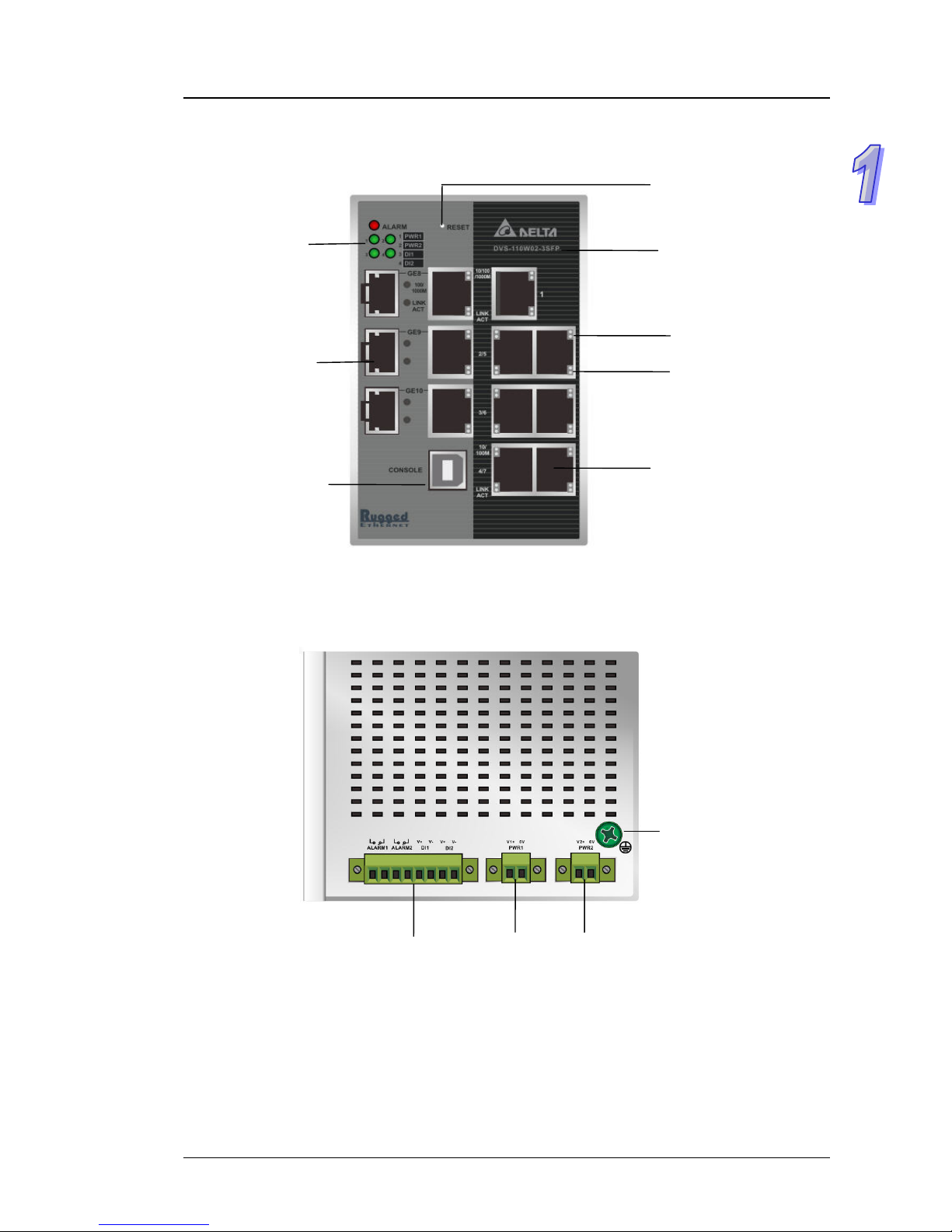
1.1.4 Front Panel Ports and LEDs
SFP combo ports
Model Name
Link/Act LED
Speed LED
Reset Button
USB console port
RJ45 ports
Alarm LED
PWR LED
DI LED
1.1.5 Bottom Panel
Grounding Screw
Power portsDI & DO ports
1-3
Page 11

DVS Series Managed Industrial Ethernet Switches User’s Manual
1.2 SFP Module Installation
Insert:
Insert SFP Module into the SFP combo port.
Remove:
Pull the tab on the module, and then pull out it.
Note:
Delta has LCP-155 and LCP-1250 series SFP module. DVS switch can promise
100% compatible with Delta SFP module.
Note:
The actual link distance of a particular fiber optic link given the optical bu dget, the
number of connectors and splices, and cabling quantity. Please measure and verify
the actual link loss values once the link is established to identify any potential
performance issues.
1-4
Page 12

Chapter 1 Introduction
1.3 Package Checklist
One Delta DVS Managed Ethernet Switch
Protective Caps for unused RJ45 ports
DIN-Rail clip x1
Wall mounting Plate x1
USB Type A to Type B console cable x1
User manual and software CD
Instruction Sheet
1-5
Page 13

DVS Series Managed Industrial Ethernet Switches User’s Manual
1-6
MEMO
Page 14

Chapter 2 User Interface Introduction
Table of Contents
2.1 USB Console Configuration.......................................................................2-2
2.2 Telnet Console Configuration ....................................................................2-4
2.3 Web Browser Configuration.......................................................................2-5
2-1
Page 15
DVS Series Managed Industrial Ethernet Switches User’s Manual
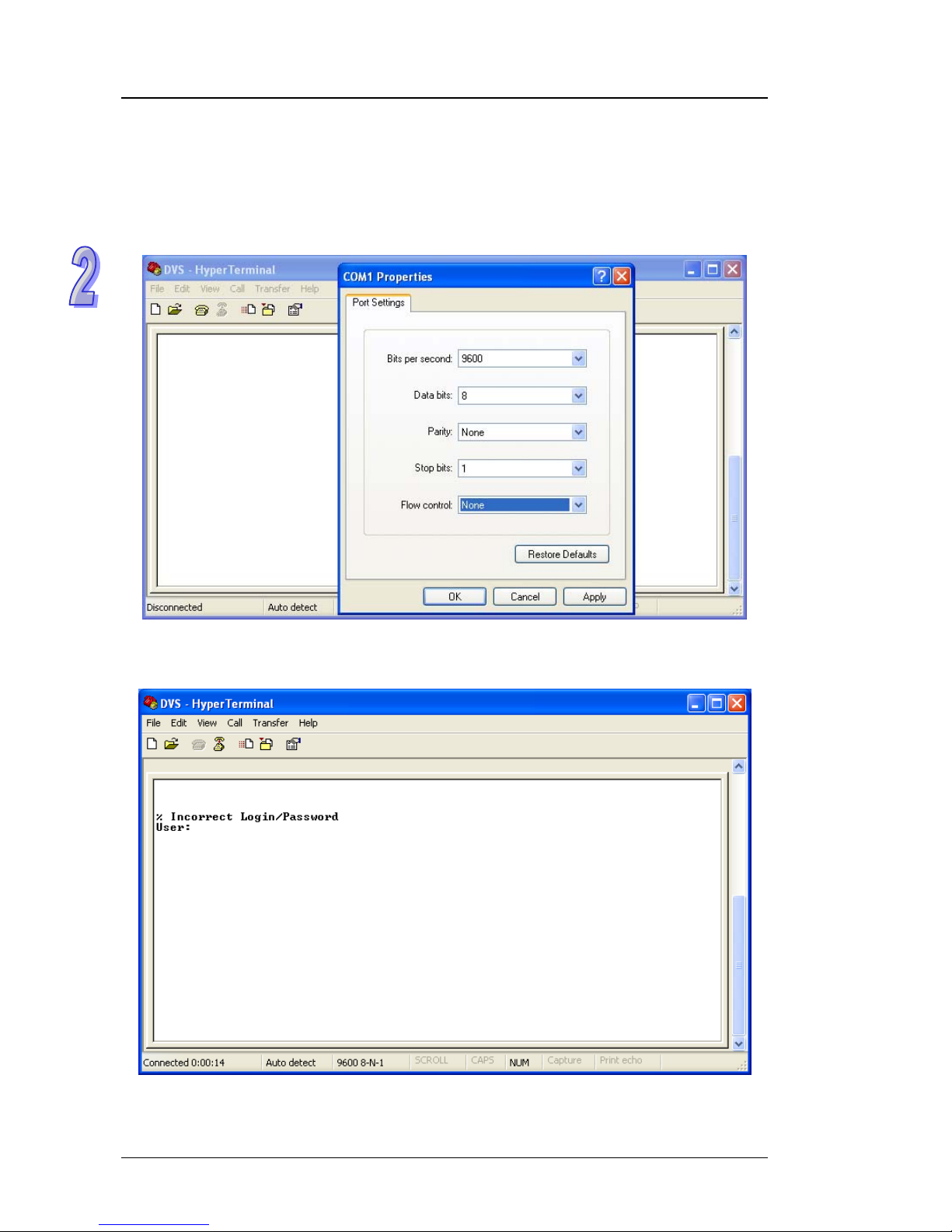
2.1 USB Console Configuration
Delta switch supports configuration usin g CLI interface, available on the USB port with baud rate
9600. You can use terminal software to connect to Delta switch. The inactivity timeout value on a
serial port connection can be configured between 0 and 160 minut es. (Value 0: disable the ti meout.)
1. Open terminal software, and select an appropriate COM port for Console Co nnection, 9600 for
Baud Rate, 8 for Data Bits , None for Parity, and 1 for Stop Bits, None for Flow Control.
2. The user name and password are the same a s W eb Browse r. The default user name is “admin”,
and password is blank.
2-2
Page 16
Chapter 2 User Interface Introduction
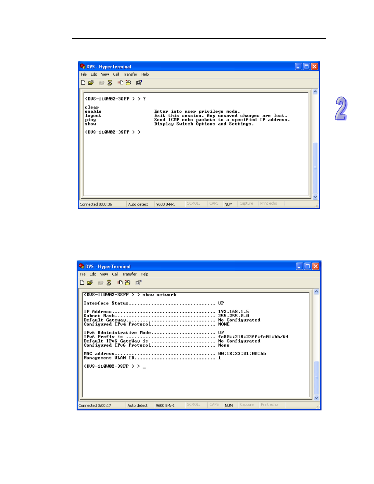
3. You can use “?” to list the commands.
Example 1:
There is a DHCP server in your environment, and the Delta switch can g et an IP address from
the DHCP server . If you don’t want to check the IP addre ss from the DHCP se rver, then you can
use USB console cable to login to Delta switch. Use “show network” command can display the
IP address information of the Delta switch.
2-3
Page 17
DVS Series Managed Industrial Ethernet Switches User’s Manual
Example 2:
Use CLI commands to set a static IP address and su bnet mask.
(DVS-1 10W02-3SFP) > enable
(DVS-1 10W02-3SFP) # configure terminal
(DVS-1 10W02-3SFP) (config)# interface vlanmgmt
(DVS-1 10W02-3SFP) (config-if)# no ip address
(DVS-1 10W02-3SFP) (config-if)# ip address 10.10.10.1 255.255.255.0
(DVS-11
0W02-3SFP) (config-if)# exit
(DVS-1 10W02-3SFP) (config)# exit
(DVS-110W02-3SFP) # save
Building configuration ...
[OK]
(DVS-110W02-3SFP) #
Note:
Before you use USB console configuration, please make sure you have installed a
USB driver. You can find the driver in the CD.
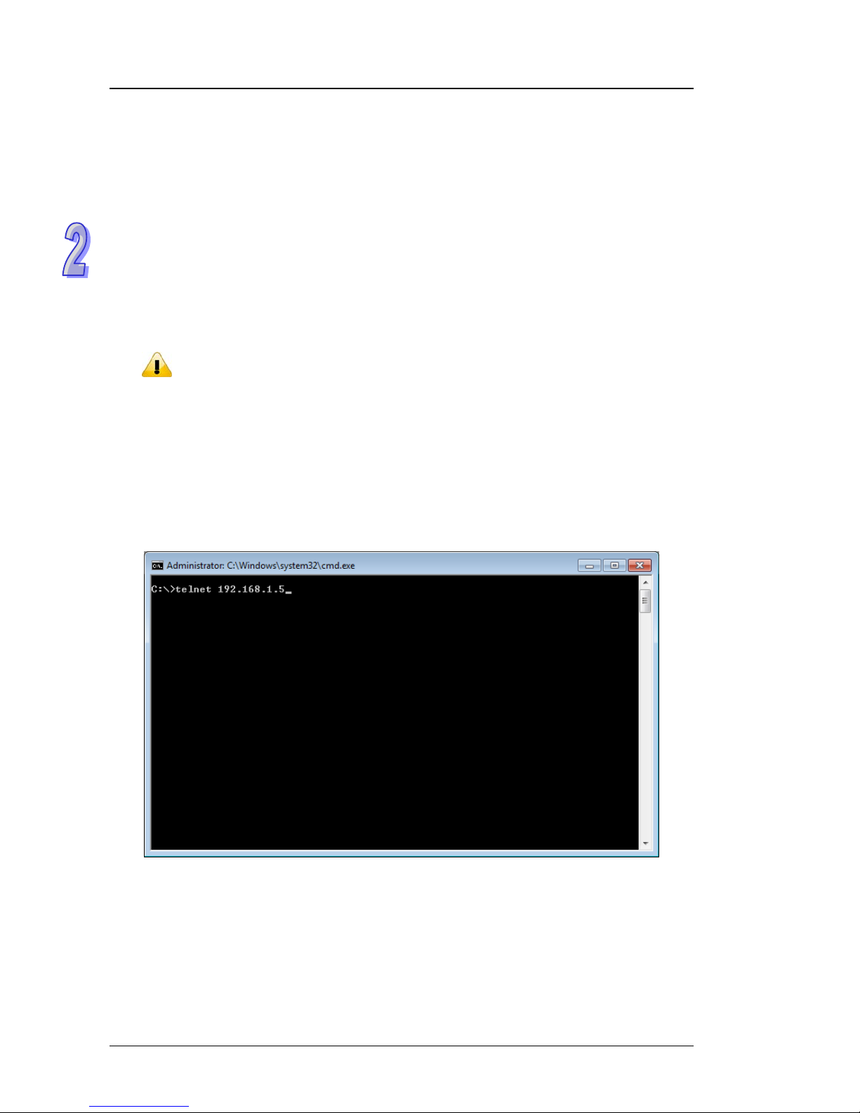
2.2 Telnet Console Configuration
A Delta switch supports telnet server function; it can be globally enabled or disabled. The user can
use all CLI command over a telnet session. The maximum number of inbound telnet se ssions
allowed on the switch can be configured to 0-5. The Inactivity timeout value for incoming Telnet
sessions to the switch can be configured to 1-160 minutes. Login authentication supports local user
method or remote user method as configured. When login authentication is remote user method, is
supports RADIUS and TACACS+.
1. Open a Command Prompt and input “telnet 192.168.1 . 5” to login to a Delta switch.
2-4
Page 18
Chapter 2 User Interface Introduction
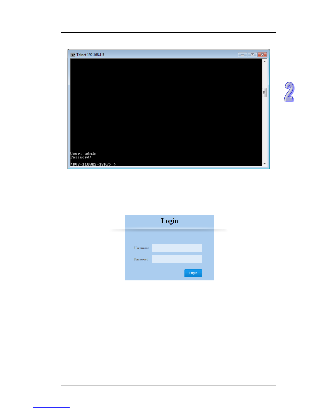
2. After entering a user name and a password, you can use CLI command to control the switch.
2.3 Web Browser Configuration
Delta switch supports a friendly we b interface for normal user to configure the switch. You can
monitor the port status of Delta switch, and configure the settings of each function via the web.
1. Open a web browser and connect to default IP address: 192.168.1.5. Enter a user name and a
password. (The default user name is “admin” and password is blank.)
2-5
Page 19

DVS Series Managed Industrial Ethernet Switches User’s Manual
2. You can use the menu tree in the left side frame to find the function you want to configure. And
configure the detail settings in the right side frame.
3. The port status and LED status on the switch can be monitored on the top frame. The status of
the Delta switch on the top frame displays the real status with the physical switch
synchronously.
2-6
Page 20

Chapter 3 Featured Functions
Table of Contents
3.1 Basic Setting .............................................................................................3-4
3.1.1 System Information ............................................................................3-4
3.1.2 Network Interface...............................................................................3-5
3.1.2.1 IPv4 Network Configuration ........................................................3-5
3.1.2.2 IPv6 Network Configuration ........................................................3-6
3.1.2.3 IPv6 Network Neighbor...............................................................3-7
3.1.3 Port Settings.......................................................................................3-8
3.1.3.1 Port Settings................................................................................3-8
3.1.3.2 LAG Settings...............................................................................3-9
3.1.4 Time .................................................................................................3-10
3.1.4.1 SNTP Scalars Configuration .....................................................3-10
3.1.4.2 SNTP Unicast Server Configuration..........................................3-11
3.1.5 DHCP/BootP Settings ......................................................................3-12
3.1.5.1 DHCP Server ............................................................................3-13
3.1.5.2 DHCP Relay..............................................................................3-15
3.1.5.3 DHCP L2Relay..........................................................................3-17
3.1.6 DNS..................................................................................................3-21
3.1.6.1 DNS Configuration....................................................................3-21
3.1.6.2 Host Configuration ....................................................................3-22
3.1.7 System File Update..........................................................................3-23
3.1.7.1 Download File ...........................................................................3-23
3.1.7.2 Upload File................................................................................3-25
3.1.8 Management Access........................................................................3-26
3.1.8.1 HTTP Configuration ..................................................................3-26
3.1.8.2 HTTPS ......................................................................................3-27
3.1.8.3 SSH Configuration ....................................................................3-30
3.1.8.4 Telnet Configuration ..................................................................3-31
3.1.8.5 Console Port .............................................................................3-31
3.2 SNMP Manager.......................................................................................3-32
3.2.1 SNMP V1/V2....................................................................................3-32
3.2.1.1 Community Configuration..........................................................3-32
3.2.1.2 Trap Configuration.....................................................................3-33
3.2.1.3 Trap Flags.................................................................................3-34
3.2.2 SNMP V3..........................................................................................3-35
3.2.2.1 User Configuration....................................................................3-36
3.3 Network Redundancy..............................................................................3-37
3.3.1 STP..................................................................................................3-37
3.3.1.1 STP Configuration.....................................................................3-41
3.3.1.2 CST Configuration.....................................................................3-42
3.3.1.3 CST Port Configuration.............................................................3-45
3.3.1.4 CST Port Status ........................................................................3-48
3.3.1.5 MST Configuration....................................................................3-51
3.3.1.6 MST Port Status........................................................................3-52
3.3.1.7 STP Statistics............................................................................3-54
3.4 Virtual LANs ............................................................................................3-55
3-1
Page 21

3.4.1 VLAN Configuration.........................................................................3-56
3.4.2 VLAN Membership...........................................................................3-57
3.4.3 VLAN Status.....................................................................................3-58
3.4.4 Port PVID Configuration...................................................................3-58
3.4.5 GVRP Configuration ........................................................................3-60
3.5 Multicast Filtering....................................................................................3-60
3.5.1 IGMP Snooping Configuration .........................................................3-63
3.5.2 IGMP VLAN Configuration...............................................................3-64
3.5.3 IGMP Snooping Multicast Forwarding Table....................................3-65
3.5.4 Multicast MAC Address Configuration..............................................3-65
3.5.5 GMRP Configuration........................................................................3-66
3.5.6 Multicast Forwarding Table ..............................................................3-67
3.6 Traffic Prioritization..................................................................................3-67
3.6.1 QoS..................................................................................................3-67
3.6.1.1 QoS Setting ..............................................................................3-68
3.6.1.2 CoS Queue Mapping ................................................................3-69
3.6.1.3 DSCP Queue Mapping .............................................................3-70
3.7 Traffic Control..........................................................................................3-71
3.7.1 Port Protected..................................................................................3-71
3.8 Port Bandwidth........................................................................................3-71
3.8.1 Storm Control...................................................................................3-71
3.8.1.1 Storm Control Setting................................................................3-72
3.8.1.2 Rate Limiting.............................................................................3-73
3.9 Port Trunking...........................................................................................3-74
3.9.1 LAG..................................................................................................3-74
3.9.1.1 LAG Membership......................................................................3-75
3.9.1.2 LAG Information........................................................................3-75
3.10 Access Control List..............................................................................3-75
3.10.1 MAC ACL......................................................................................3-76
3.10.2 MAC Rules...................................................................................3-77
3.10.3 MAC Binding Configuration..........................................................3-79
3.10.4 Binding Table................................................................................3-80
3.11 Security Settings..................................................................................3-80
3.11.1 Security ........................................................................................3-80
3.11.1.1 Port Security..........................................................................3-81
3.11.1.2 IP Source ..............................................................................3-83
3.11.1.3 Port Authentication................................................................3-83
3.11.2 Management Security ..................................................................3-90
3.11.2.1 Local Users Management .....................................................3-90
3.11.2.2 RADIUS Server Config..........................................................3-91
3.11.2.3 RADIUS Statistics..................................................................3-92
3.11.2.4 TACACS+ Server ..................................................................3-93
3.11.2.5 TACACS+ AS ........................................................................3-94
3.11.2.6 Login Authentication..............................................................3-94
3.11.2.7 Login User Sessions .............................................................3-95
3.11.3 Denial of Service..........................................................................3-96
3.12 Monitoring Settings..............................................................................3-97
3.12.1 Mac Address T able.......................................................................3-98
3.12.2 SFP DDM.....................................................................................3-99
3-2
Page 22

3-3
3.12.3 System CPU Status ......................................................................3-99
3.12.4 Interface Statistics.......................................................................3-100
3.12.5 RMON.........................................................................................3-100
3.12.5.1 Basic Settings......................................................................3-100
3.12.5.2 Alarms .................................................................................3-101
3.12.5.3 Events..................................................................................3-103
3.12.5.4 Event Log ............................................................................3-103
3.12.5.5 History .................................................................................3-104
3.12.5.6 RMON Ethernet Statistics....................................................3-104
3.12.5.7 Ethernet History Statistics....................................................3-106
3.12.6 SYSLOG.....................................................................................3-108
3.12.6.1 Show Logs...........................................................................3-108
3.12.6.2 Logs Configuration ..............................................................3-109
3.12.6.3 Syslog Fwd Table ................................................................3-111
3.12.6.4 Syslog Email Configuration..................................................3-112
3.12.6.5 Syslog Email Alarm Table ....................................................3-113
3.13 Diagnostic Settings............................................................................3-115
3.13.1 LLDP...........................................................................................3-115
3.13.1.1 LLDP Basic Settings............................................................3-115
3.13.1.2 LLDP Interface Configuration ..............................................3-116
3.13.1.3 LLDP TLV Options...............................................................3-117
3.13.1.4 LLDP Local Information.......................................................3-118
3.13.1.5 LLDP Neighbor Information.................................................3-119
3.13.1.6 LLDP Traf fic.........................................................................3-121
3.13.1.7 LLDP-MED Global Configuration.........................................3-121
3.13.1.8 LLDP-MED Interface Configuration.....................................3-122
3.13.2 Port Mirroring..............................................................................3-123
3.13.2.1 Multiple Port Mirroring .........................................................3-123
3.14 Auto Warning.....................................................................................3-125
3.14.1 Relay Alarm ................................................................................3-125
3.14.1.1 Relay Alarm Setting.............................................................3-125
3.14.1.2 Relay Alarm T able................................................................3-128
3.15 Dual Image ........................................................................................3-128
3.15.1 Copy...........................................................................................3-128
3.15.2 Configuration ..............................................................................3-129
3.16 Save Config.......................................................................................3-129
3.16.1 Save Configuration.....................................................................3-129
3.16.2 Erase..........................................................................................3-130
3.17 Reset .................................................................................................3-130
3.17.1 Device Reboot............................................................................3-130
3.17.2 Factory Default Settings .............................................................3-130
3.18 Troubleshooting.................................................................................3-131
3.18.1 Ping IPv4 ....................................................................................3-131
3.18.2 Ping IPv6 ....................................................................................3-132
3.18.3 Traceroute IPv4..........................................................................3-133
3.18.4 Traceroute IPv6..........................................................................3-133
Page 23

DVS Series Managed Industrial Ethernet Switches User’s Manual
3.1 Basic Setting
The basic setting group includes most common settings, and an administrator can maintain control
the Delta switch in this group.
3.1.1 System Information
Some information of switch status items and versions are displayed in the banner of GUI. The
information can help the administrator identify the switch in the network.
Switch Status
Description Factory Default
System Name
Input the system name of the switch. None
System Location
Input the system location of the switch. None
System Contact
Input the system contact of the switch. None
Serial Number
The serial number of the switch. Fixed
System Object ID
The base object ID for the Management Information Base (MIB) of the
switch.
Fixed
IMPORTANT:
Make sure that you save the configuration in the Save
Configuration page after you have applied the configuration
changes. (Save ConfigSave Configuration) If you don’t
save the configuration, then the configuration will be cleared
after the switch is rebooted.
3-4
Page 24

Chapter 3 Featured Functions
Description Factory Default
Date & Time
The current date and time. None
System Up Time
The time of hours, minutes, and seconds since the switch was last
started.
None
Base MAC Address
The MAC address of the switch. Fixed
Versions
Description Factory Default
Model Name
The model name of the switch. Model Name
Boot Version
The boot version of the switch. Boot Version
Software Version
The software version of the switch. Software Version
3.1.2 Network Interface
The network interface on the network device is a logical interface. Each network device must have
one or more interfaces to connect with other network devices. But the configuration of the network
interface doesn’t affect the traffic which is forwarded.
3.1.2.1 IPv4 Network Configuration
You can configure a static IP address, subnet mask and default gateway for the switch. O r you can
enable DHCP or BOOTP for receiving a dynamic IP address, subnet mask and default gateway. If
you enable DHCP or BOOTP, but there is no DHCP or BOOTP server in the n etwork, the default link
local IP address will be 169.254.100.100.
Note:
The default Current Network Configuration Protocol is None.
And the default IP address is 192.168.1.5.
3-5
Page 25

DVS Series Managed Industrial Ethernet Switches User’s Manual
IPv4 Network Interface Configuration
Description Factory Default
IP Address
Input the IP address of the IPv4 network interface. 192.168.1.5
Subnet Mask
Input the IP subnet mask of the IPv4 network interface. 255.255.0.0.
Default Gateway
Input the default gateway of the IPv4 network interface. 0.0.0.0.
MAC Address
This field displays the MAC address of the switch. MAC address
Current Network Configuration Protocol
Select one item to specify how the switch gets its IP information:
None: Specify static IP address information.
DHCP: The IP information of the switch is assigned from a Dynamic
Host Configuration Protocol (DHCP) server on the network.
BOOTP: The IP information of the switch is assigned from a
Bootstrap Protocol (BOOTP) server on the network.
None
Management VLAN ID
Input the management VLAN ID in the range from 1 to 4094. 1
3.1.2.2 IPv6 Network Configuration
If you need to configure a global IPv6 address, please follow the standard format:
“IPv6 Prefix/Prefix Length”. For example: “1001:2002:3003::7007:8008/64”
Global Configuration
Description Factory Default
Admin Mode
Specify the IPv6 administrative status of the network interface by
selecting one item:
Disable: IPv4 only mode. Only support IPv4, not support IPv6.
Enable: IPv4 / IPv6 mode. Support both IPv4 and IPv6.
Enable
IPv6 Gateway
Input the IPv6 address of the IPv6 gateway. None
3-6
Page 26

Chapter 3 Featured Functions
IPv6 Network Interface Configuration
Description Factory Default
IPv6 Prefix / Prefix Length
Enter the IPv6 address followed by a slash and then the prefix length of
the network interface.
IPv6 address
EUI64
Specify whether the IPv6 address is in the 64-bit extended unique
identifier (EUI-64) format:
True: The IPv6 address is in the EUI-64 format.
False: The IPv6 address is not in the EUI-64 format.
None
Note:
An IPv6 address in the EUI-64 format is an automatically self-assigned unique 64-bit
IPv6 interface identifier. You do not need to manually configure such an IPv6
address, nor is it assigned by a DHCP server.
3.1.2.3 IPv6 Network Neighbor
The IPv6 network interface neighbor table can display the neighbor IPv6 address.
IPv6 Network Interface Neighbor Table
Description Factory Default
IPv6 Address
The IPv6 address of the neighbor. None
MAC Address
The MAC address of the neighbor. None
Neighbor State
The status of the neighbor:
Static: The neighbor has a static IP address.
Reachable: The neighbor was reached very recently (that is, within
a period of tens of seconds).
Incomplete: Address resolution for the neighbor is in progress, but
the link-layer address of the neighbor has not yet been determined.
Stale: The neighbor can no longer be rea ched: Until traf fic is sent to
the neighbor, no attempt is made to verify if it can be reached again .
Delay: The neighbor can no longer be reached: Traffic was recently
sent to the neighbor, but ne ighbor solicitation probes are delayed
because confirmation that the neighbor can be reached might be
received.
Probe: The neighbor can no longer be reached: Unicast neighbor
solicitation probes are sent to verify if the neighbor can be rea ch ed
again.
Unknown: The status of the neighbor is unknown.
None
3-7
Page 27

DVS Series Managed Industrial Ethernet Switches User’s Manual
3.1.3 Port Settings
You can configure the basic port settings, green Ethernet settings and LAG settings on the switch in
Port Settings group.
3.1.3.1 Port Settings
You can configure and monitor the port status in this page.
Port Settings
Description Factory Default
Port
This field displays the interface number.
interface number
Link Status
This field displays the connection of the interface.
Link Up: There is a network device connecting to the interface.
Link Down: No network device is connecting to the interface.
Link down
Admin Mode
The administrative state of the interface:
Enable: The interface is switched on and the network device can
connect to the interface.
Disable: The interface is switched off and the network device can’t
connect to the interface.
Enable
Port Type
This field displays whether the interface is a member of a port channel:
Trunk Member: The interface i s a member of a link aggregation
group.
Normal: The interface is not a member of a link aggregation group
(port channel).
Normal
3-8
Page 28

Chapter 3 Featured Functions
3-9
Description Factory Default
Physical Mode
Specify the port to auto-negotiation, or a specific spee d and duplex
mode for the interface:
Auto: The duplex mode and speed of the interface are set by the
auto-negotiation process. The interface can support the maximum
capability: Full duplex and 1 Gbps or 100Mbps.
10 Mbps Half Duplex: Indicates the interface works at 10 Mbps in
the half duplex mode.
10 Mbps Full Duplex: Indicates the interface works at 10 Mbps in
the full duplex mode.
100 Mbps Half Duplex: Indicates the interface works at 100 Mbps in
the half duplex mode.
100 Mbps Full Duplex: Indicates the interface works at 100 Mbps in
the full duplex mode.
Auto
Physical Status
This field displays the actual port speed and duplex mode. None
Flow Control Mode
This field displays whether flow control is enabled for the port:
Enable: Flow control is enabled. If the port buffers become full, the
switch sends pause packets.
Disable: Flow control is disabled. If the port buffers become full, the
switch does not send pause packets.
Disable
Jumbo Frame
The field displays whether jumbo frame is enabled for the port.
Enable: Jumbo frame is enabled. The switch supports a fixed jumbo
frame size - 9000 bytes payload (9018 bytes frame) size.
Disable: Jumbo frame is disabled.
Disable
Link Trap
Specify whether to send a trap wh en the interface link status changes:
Enable: When the link status changes, the switch sends a trap. This
is the default setting.
Disable: When the link status changes, the switch does not send a
trap.
Enable
3.1.3.2 LAG Settings
You can configure LAG settings and monitor LAG status in this page.
Page 29

DVS Series Managed Industrial Ethernet Switches User’s Manual
LAG Settings
Description Factory Default
Port
This field shows the interface number.
interface number
Link Status
This filed show the connection of the interface.
Link Up: The interface is connected to another device.
Link Down: The interface is not connected to another device.
Link Down
Admin Mode
Specify the administrative state of the in terface:
Enable: The interface is switched on and can be connected to
another device.
Disable: The interface is switched off and cannot be connected to
another device.
Enable
Jumbo Frame
The filed displays whether jumbo frame is enabled for the port.
Enable: Jumbo frame is enabled. The switch supports a fixed jumbo
frame size - 9000 bytes payload (9018 bytes frame) size.
Disable: Jumbo frame is disabled.
Disable
Link Trap
Specify whether the switch sen ds a trap when the interface link status
changes:
Enable: When the link status changes, the switch sends a trap. This
is the default setting.
Disable: When the link status changes, the switch doesn’t send a
trap.
Enable
3.1.4 Time
The switch supports SNTP (Simple Network Time Protocol). It can work as an SNTP client to get
time from an SNTP or NTP server, and it also can work as an SNTP server to provide time service
and send a time reply to a client.
3.1.4.1 SNTP Scalars Configuration
The SNTP Scalars Configuration lets a user to configure the time of the switch which gets from
SNTP server or not. And it also can be configured manually.
3-10
Page 30

Chapter 3 Featured Functions
SNTP Scalars Configuration
Description Factory Default
SNTP Client Status
Specify whether the switch works a s an SNTP client, and the switch wil l
send an NTP request to the server which the user specify in SNTP
Unicast Server Configuration page.
Enable: The switch works as an SNTP client.
Disable: The switch doesn’t work as an SNTP client.
Disable
SNTP Server St atus
Specify whether the switch works as an SNTP server.
Enable: The switch works as an SNTP serve r.
Disable: The switch doesn’t work as an SNTP server.
Disable
Date
The date parameter format is DD/MM/YYYY.
When an SNTP client is disabled, you can manually set the date. When
an SNTP client is enabled, the field is grayed out.
DD/MM/YYYY
Time
The time parameter format is HH:MM:SS.
When an SNTP client is disabled, you can manually set the time. When
an SNTP client is enabled, the field is grayed out.
HH:MM:SS
Time Zone
The time zone setting format is HH:MM is preceded by a plus (+) or
minus (-). For example, for Taipei, enter +08:00. And it allows
conversion from GMT (Greenwich Mean Time) to the local time.
+00:00
DST StarTim e
Enter the daylight saving time (DST) start time. Specify the date and
time in the following format:
week of the month-day of the week-month-HH:MM.
For example, if DST starts on the first Saturday in May at 03:00 AM,
enter the following format: First-Sat-May,03:00.
None
DST EndTime
Enter the daylight saving time (DST) end time. Specify the date and
time in the following format:
week of the month-day of the week-month-HH:MM.
For example, if DST ends on the second Monday in December at 04:00
AM, enter the following format: Second-Mon-Dec,04:00.
None
Note:
1. After you have clicked Apply, the date and time are applied and the fields revert
to their default setting of DD/MM/YYYY and HH:MM:SS.
2. The manual date and time setting will be lost after the switch is rebooted, even if
you have saved the changes
3.1.4.2 SNTP Unicast Server Configuration
If you want to specify a known SNTP server, you can enter the IP address or DNS in this page.
3-11
Page 31

DVS Series Managed Industrial Ethernet Switches User’s Manual
SNTP Unicast Server Configuration
Description Factory Default
Forward Address Type
Specify the type of SNTP server IP address:
IPv4: Use an IPv4 address to recognize an SNTP server. This is the
default setting.
IPv6: Use an IPv6 address to recognize an SNTP server.
DNS: Use FQDN to recognize an SNTP server.
IPv4
Unicast Server IP Address
Enter the server IPv4, IPv6 address or host name (FQDN). (Depend on
which type you select in the Forward Addre ss Type field.)
None
Unicast Server Type
Specify the type of server by selecting Primary or Se condary from the
drop-down list.
None
Last Updated
This field displays the last time the SNTP unicast server updated its
time information.
None
Tx Requests
This field displays the number of SNTP transmit requests made by the
switch since it was last rebooted.
None
Note:
We recommend you add SNTP unicast server for Delta switch to synchronize the
time. It can make sure the time on Delta switch is accurate.
3.1.5 DHCP/BootP Settings
The switch can function as a DHCP server, DHCP relay and DHCP L2 relay. If there is n o DHCP
server in your network, then you can enable a DHCP server function. If there is a DHCP server in
your network, then you can configure a switch to function as a DHCP relay. If there are already a
DHCP server and a DHCP relay in your network, or there are L2 de vices between DHCP clien ts an d
relay agents, then you can configure the switch to function as a DHCP L2 rel ay in this network.
3-12
Page 32

Chapter 3 Featured Functions
3.1.5.1 DHCP Server
If the DHCP server is enabled on the switch, it can assign an IP address which is in the same
network as the switch to the client.
DHCP Server Configuration
You can enable or disable the DHCP server function and configure the DHCP configuration in
this page.
DHCP Server Configuration
Description Factory Default
Admin Mode
Specify the status of the DHCP server on the switch:
Disable: The DHCP server is disabled. When you want to enable
the DHCP relay function, please select this setting.
Enable: The DHCP server is enabled.
Disable
Next Server
Specify Boot server host name. 0.0.0.0
Boot File
Specify Boot file name. None
Network
Enter the network for the DHCP pool. None
Subnet Mask
Enter the IP subnet mask for the DHCP pool. None
Lease Time Type
Specify the type of lease time:
Specified Duration: The leased IP address has a specific duration.
You need to specify the duration in the Lease Time fields.
Infinite: The leased IP address does not expire.
None
3-13
Page 33

DVS Series Managed Industrial Ethernet Switches User’s Manual
3-14
Description Factory Default
Lease Time
If you select Specified Duration from the Lease Time Type in the
drop-down list, specify the duration by entering the days, hours, and
minutes in the Lease Time fields.
None
Default Router
Specify the default gateway IP address. The information will be
included in DHCP offer packet.
None
DNS Server
Specify the DNS server IP address. The information will be included in
DHCP offer packet.
None
Domain Name
Specify the Domain Name. The information will be included in DHCP
offer packet.
None
Excluded Addresses
Description Factory Default
IP Range From
Enter the start IP address of the exclusion IP range which you created
in the DHCP server pool.
None
IP Range To
Enter the end IP address of the exclusion IP range which you created
in the DHCP server pool.
None
DHCP Pool Options
DHCP messages contain many option fields. These options have many control information and
configuration parameters.
DHCP Server Pool Option Configuration
Description Factory Default
Option Code
Enter the option code. For example, option code 3 is router, 6 is
Domain Name Server. (If you nee d more information, please find
RFC2132, DHCP Options and BOOTP Vendor Extensions.)
None
Option T ype
Specify the option type:
ASCII: Enter ASCII value in the Option Value field.
Hex: Enter Hex value in the Option Value field.
IP Address: Enter IP address or subnet mask in the Option Value field.
None
Option Value
Enter the value that corresponds to the Option Type you select. None
Page 34

Chapter 3 Featured Functions
DHCP Server Binding
If the DHCP function is enabled, you can see the DHCP client’s information in this page.
DHCP Bindings Configuration
Description Factory Default
IP Address
The IP address of the DHCP client. None
Hardware T y pe
This field displays the type of hardware address of the client.
0: If the client uses DHCP option 61 to specify itself, the hardware
type is Client ID, and the hardware address is the string identifier.
1: The hardware type is Ethernet, and the hardware address is an
MAC address.
None
Hardware Address
This field displays the MAC address or string identifier of the DHCP
client.
None
Expire Time
The expiration time of the DHCP client. None
3.1.5.2 DHCP Relay
A DHCP Relay can make broadcast messages to be sent over routers. An d a DHCP relay can
receive a DHCP broadcast request packet and forward it to a specified server.
Notice:
When a DHCP request packet comes, a DHCP relay receives it and then sends it to
all VLANs. But according to RFC 2131, when renewing, unicast DHCP request
packet will be sent to a DHCP server directly, not passing a DHCP relay, so it is
recommended to make sure that the DHCP client can ping the server after getting
an IP address.
DHCP Relay Configuration
DHCP Relay sends a unicast DHCP packet to the specified server(s). The maximum number of
specified servers is 5. You can enable or disable a DHCP relay function, and configure the
3-15
Page 35

DVS Series Managed Industrial Ethernet Switches User’s Manual
parameters of circuit ID sub-option (the interface ID on the switch which connect s to the host)
and remote ID sub-option (the MAC address of the host which sends DHCP request) in this
page.
DHCP Relay
Configuration
Description Factory Default
Admin Mode
Specify the status of the DHCP relay on the switch:
Disable: The DHCP relay is disabled. This is the default setting.
Enable: The DHCP relay is enabled.
Disable
Circuit ID sub-option
Specify whether circuit ID sub -option (the interface ID of the switch) is
enabled.
Disable: Circuit ID can’t be added into a DHCP packet. This is the
default setting.
Enable: Circuit ID can be added into a DHCP packet.
Disable
Remote ID sub-option
Enter a remote ID string (the MAC address of the host which sends the
DHCP request) for the circuit ID mode. This is a local identifier of the
circuit from which a DHCP client-to-server packet is received. It
ensures that the DHCP relay sends DHCP serv er responses back to
the correct circuit.
None
DHCP Relay Statistics
3-16
Page 36

Chapter 3 Featured Functions
DHCP Relay Statistics
Description Factory Default
No of Packets inserted Circuit-Id option
The amount of Packets which inserted Circuit-Id option. 0
No of Packets inserted Remote-Id suboption
The amount of Packets which inserted Remote-Id suboption. 0
No of Packets dropped
The amount of Packets which dropped. 0
No of Packets which did not inserted RAI option
The amount of Packets which did not insert RAI (Relay Agent
Information) option.
0
3.1.5.3 DHCP L2Relay
In some networks, DHCP servers rely on Relay Agent Information option append ed by Relay Agent s
for IP address and other parameter assi gnment policies. This works fine whe n end host s are directly
connected to Relay Agents. In some network configurations, one or more Layer 2 devices may
reside between DHCP client s and a Relay agent. In these network scenarios, it is difficult to use the
Relay Agent Information option for an IP address and other parameter assignment policies
effectively. So there is a requirement for the device that is closest to the end hosts to append a
Relay Agent Information option in DHCP messages. These devices are typically known as Layer 2
Relay Agents.
DHCP snooping steps:
1. A DHCP client sends a DHCP request via broadcast.
2. When a switch (relay agent) receives the DHCP request, it will add DHCP option-82 to the
packet. DHCP option-82 includes the MAC address of the host which sends a DHCP request
(remote-ID sub-option) and the interface ID on the switch which connect s to the h ost (circuit-ID
sub-option).
3-17
Page 37

DVS Series Managed Industrial Ethernet Switches User’s Manual
3. If the switch has configured an IP address, the IP address will be added into the DHCP packet.
4. If a DHCP server supports option-82, after the DHCP server receives the DHCP request, it will
allocate the IP address numbers according to the remote-ID sub-option or circuit ID sub-option.
5. A DHCP server responds to the switch via unicast. And the switch checks whether the
remote-ID or circuit-ID in option-82 matches the value of the DHCP request, and makes sure it
sends from the certificated DHCP server. Then it removes the information of option-82, and
sends back to the interface on the switch which sends the DHCP request.
DHCP L2 Relay Global Configuration
You can enable or disable a DHCP relay function, and configure the parameters of circuit ID
sub-option (the interface ID on the switch which connects to the host) and remote ID sub-option
(the MAC address of the host which sends DHCP request) in this page.
DHCP L2 Relay
Configuration
Description Factory Default
DHCP L2 Relay Configuration
Admin Mode
Specify whether the global status of the DHCP relay is enabled.
Enable: The DHCP relay function is enabled.
Disable: The DHCP relay function is disabled. This is the default
setting.
Disable
DHCP L2 Relay VLAN Configuration
Description Factory Default
VLAN ID
If you have added VLANs on the VLAN Configuration page, the VLANs
can be shown in the VLAN ID column, and you can configure the
DHCP L2 relay setting of each VLAN.
1
Admin Mode
Specify whether the status of the DHCP relay is enabled on the VLAN:
Enable: Enable the DHCP relay on the VLAN. Y ou can configu re the
VLAN DHCP relay settings if the DHCP relay is globally disabled.
But the settings do not take effect even if you have applied it.
Disable: Disabled the DHCP relay on the VLAN.
Disable
Circuit ID
Specify whether the DHCP relay agent information option (DHCP
option 82) is enabled:
Enable: Enable the relay agent information option.
Disable: Disable the relay agent information option. This is the
default setting for default VLANs 1, 2, and 3.
Disable
3-18
Page 38

Chapter 3 Featured Functions
3-19
Description Factory Default
Remote ID String
Enter the remote ID string for the circuit ID mode. This is a local
identifier of the circuit from which a DHCP client-to-server packet is
received. It can make sure that the DHCP relay responds to packet s
from the DHCP server to the correct circuit.
None
DHCP L2 Relay Interface Configuration
The interface which is connected to a DHCP server is a trusty interf ace; the interface which
connected to DHCP client is an untrustful interface.
Trusted port:
(a) When a DHCP request packet with opt82 is received, it will be forwarded.
(b) When a DHCP reply packet with opt82 is received, if the remote id is same as the
switch’s id, the opt82 will be stripped and forwarded; if the remote id is not same as the
switch’s id, it will be forwarded directly.
(c)When a DHCP packet without opt82 is received, it will be dropped.
Un-trusted Port:
(a) When a DHCP packet with opt82 is received, it will be dropped.
(b) When a DHCP packet without opt82 is received, opt82 will be inserted and the packet
will be forwarded.
DHCP L2 Relay Configuration
Description Factory Default
Interface
The interface number.
interface number
Page 39

DVS Series Managed Industrial Ethernet Switches User’s Manual
3-20
Description Factory Default
Admin Mode
Specify whether the DHCP relay is enabled on the interface:
Enable: Enable the DHCP relay on the interface. If the DHCP relay
is globally disabled on the switch, you can still configure the
interface DHCP relay settings, but the settings do not take effect
even if you have applied it.
Disable: Disable the DHCP relay on the interface.
Disable
82 Option Trust Mod e
As a security consideration, specify whether the interface is trusted
when DHCP relay agent information (DHCP option 82) is received o n
the interface:
Enable: The relay agent information that is received on the interface
can be trusted.
Disable: The relay agent information that is received on the
interface cannot be trusted and should be ignored.
Disable
DHCP L2 Relay Statistics
You can see the statistics of DHCP L2 relay messages in this page
DHCP L2 Relay Interface Statistics
Description Factory Default
Interface
The interface number.
interface number
Untrusted Server Messages With Opt82
The amount of DHCP packets with option 82 that were received from
an untrusted server.
0
Untrusted Client Messages With Opt82
The amount of DHCP packets with option 82 that were received from
an untrusted client.
0
Trusted Server Messages Without Opt82
The amount of DHCP packets without option 82 that were receive d
from a trusted server.
0
Page 40

Chapter 3 Featured Functions
3-21
Description Factory Default
Trusted Client Messages Without Opt82
The amount of DHCP packets without option 82 that were receive d
from a trusted client.
0
3.1.6 DNS
A Delta switch can function as a DNS client and forward the DNS queries to a DNS server. Y ou can
configure DNS servers manually or add them via a DHCP server.
3.1.6.1 DNS Configuration
You can configure the global DNS settings and add a DNS server manually in this page.
DNS Configuration
Description Factory Default
DNS Status
Specify whether the switch functions as a DNS client:
Disabled: The switch does not function as a DNS client and does
not send DNS queries. The settings do not take effect even if you
configure a DNS server.
Enabled: The switch functions as a DNS client and can send DNS
queries to a DNS server.
Enable
DNS Default Name
Enter the DNS default domain name to be included in DNS queries.
When the switch performs a lookup for an unqualified host name, the
DNS default domain name is provided as the domain name.
For example, if the DNS default domain name is delta.com and you
enter “dvs
” for a DNS query , then “dvs” is changed to “dvs.delta.com“ to
resolve the name. The length of the name cannot be longer than 255
characters.
None
DNS Server Configuration
Description Factory Default
Serial No
The sequence number of the DNS server in the table. If the IP address
of the DNS server was dynamically added through DHCP, the number
is followed by an asterisk (*).
None
Page 41

DVS Series Managed Industrial Ethernet Switches User’s Manual
3-22
Description Factory Default
DNS Server
The DNS server can be added manually or added dynamically through
DHCP. Delta switch can support 8 DNS servers.
None
Preference
The preference of the DNS server. The prefere nce is determined by the
order in which the IP address was added to the table. So the
preference number 1 is the first IP address that was added into the
table.
None
3.1.6.2 Host Configuration
You can map a DNS host name to an IP address in this page.
DNS Host Configuration
Description Factory Default
DNS Host Configuration
Host Name
Specify the static host name. The maximum characters are 255. None
IP Address
Specify the IP address of the host name. None
Dynamic Host Mapping
Description Factory Default
Host
The host name was added dynamically. None
Total
The total time to live (TTL) for the dynamic entry. None
Elapsed
The elapsed time since the dynamic entry was added to the table. None
Type
The type of the dynamic entry:
IPv4
IPv6
Canonical name
None
Address
The IP address of the host name. None
Page 42

Chapter 3 Featured Functions
3.1.7 System File Update
The Delta switch supports download yo ur firmware, configuration, or log file from a TFTP server or
local host. And it also supp orts upload files to a TFTP server or local host.
3.1.7.1 Download File
Delta switch supports 2 ways for user t o download files. If there is no TFTP server in your network
environment, you can choose the HTTP way to download files from local host.
TFTP Download
TFTP File Dow
nload
Description Factory Default
File Type
Specify the type of file in the drop down list that you want to download:
Archive: When you select Archive, the Image Name drop-d own list
is displayed.
Startup Configuration: When the switch boots up, the Startup
Configuration will be applied.
SSL Server Certificate PEM File. For more information about the
SSL server certificate PEM file, please see the Certificate
Information page.
Script File: This file is used to configure the switch by CLI script.
None
Image Name
Only when you select Archiv e from the File Type drop-down list is the
Image Name drop-down list displayed. Specify the image:
image1: The downloaded image firmware as image1.
image2: The downloaded image firmware as image2.
image1
Server Address Type
Specify the type of server address and enter the IP address or host
name in the Server Address field:
IPv4: The IPv4 address of a TFTP server.
DNS: The DNS host name of a TFTP server.
IPv4
3-23
Page 43

DVS Series Managed Industrial Ethernet Switches User’s Manual
3-24
Description Factory Default
Server Address
Enter an IPv4 address or a DNS host name of the TFTP server. None
Remote File Name
Enter the name of the file that you want to download to the switch. You
can enter up to 32 characters.
None
If you select Archive in the File Type drop down list, the image name item will show up. After
selecting File Type, setting up Server Address and sp ecifing Remote File Name, click Apply to
start downloading.
HTTP Download
HTTP Download
Description Factory Default
File Type
Specify the type of file in the drop down list that you want to download:
Archive: When you select Archive, the Image Name drop-d own list
is displayed.
Startup Configuration: When the switch boots up, the Startup
Configuration will be applied.
SSL Server Certificate PEM File. For more information about the
SSL server certificate PEM file, please see the Certificate
Information page.
Script File: This file is used to configure the switch by the CLI script.
None
Image Name
Only when you select Archiv e from the File Type drop-down list is the
Image Name drop-down list displayed. Specify the image:
image1: The downloaded image firmware as image1.
image2: The downloaded image firmware as image2.
image1
Select File
Specify the file that you want to download. None
If you select Archive in the File Type drop down list, the image name item will show up. After
selecting File Type and the path of the file on your PC, click Apply to start downloading.
Page 44

Chapter 3 Featured Functions
3.1.7.2 Upload File
Delta switch supports 2 ways for user t o upload files. If there is no TFTP server in your network
environment, you can chooses HTTP way to upload files.
TFTP Upload
TFTP Upload
Description Factory Default
File Type
Specify the type of file in the drop down list that you want to upload:
Archive: When you select Archive, the Image Name drop-d own list
is displayed.
Startup Configuration: When the switch boots up, the Startup
Configuration will be applied.
Backup Configuration: It’s used to backup the Startup
Configuration file.
Log: This file records the log information of the switch.
Script File: This file is used to configure the switch by CLI script.
None
Image Name
Only when you select Archiv e from the File Type drop-down list is the
Image Name drop-down list displayed. Specify the image:
image1: The uploaded image firmware as image1.
image2: The uploaded image firmware as image2.
image1
Server Address Type
Specify the type of server address and enter the IP address or host
name in the Server Address field:
IPv4: The IPv4 address of a TFTP server.
DNS: The DNS host name of a TFTP server.
IPv4
Server Address
Enter an IPv4 address or a DNS host name of the TFTP server. None
Remote File Name
Enter the name of the file that you want to upload to the switch. You
can enter up to 32 characters.
None
If you select Archive in the File Type drop down list, the image name item will show up. After
selecting File Type, setting up Server Address and sp ecifing Remote File Name, click Apply to
start uploading.
3-25
Page 45

DVS Series Managed Industrial Ethernet Switches User’s Manual
HTTP Upload
HTTP Upload
Description Factory Default
File Type
Specify the type of file in the drop down list that you want to upload:
Archive: When you select Archive, the Image Name drop-d own list
is displayed.
Startup Configuration: When the switch boots up, the Startup
Configuration will be applied.
Backup Configuration: It’s used to backup the Startup
Configuration file.
Log: This file records the log information of the switch.
Script File: This file is used to configure the switch by CLI script.
None
Image Name
Only when you select Archiv e from the File Type drop-down list is the
Image Name drop-down list displayed. Specify the image:
image1: The uploaded image firmware as image1.
image2: The uploaded image firmware as image2.
image1
If you select Archive in File Type drop down list, the image name item will show up. After
selecting File Type, click Apply and specify a path to start uploading.
3.1.8 Management Access
Delta switch supports not only one way to access web management interface. You can configure
HTTP or secure HTTP (HTTPS), and you also can configure Secure Shell (SSH), Telnet and
console port access.
3.1.8.1 HTTP Configuration
3-26
Page 46

Chapter 3 Featured Functions
HTTP Configuration
Description Factory Default
HTTP Access
Specify whether the web management interface can be accessed from
a web browser over an HTTP connection.
Disable: The web management interface can’t be accessed over an
HTTP connection. You need to use a Telnet, SSH, or console
connection to access the switch.
Enable: The web management interface can be accessed over an
HTTP connection.
Enable
HTTP Port
The HTTP port number. The number must be in the range of 1 to
65535. The default setting is port number 80.
80
HTTP Session Timeout (minutes)
The HTTP session time-out period in minutes. The HTTP session will
be closed when there is no activity and the time-out period is reached.
Enter a period in the range of 0 to 60 minutes. Entering 0 disables the
time-out.
30
3.1.8.2 HTTPS
Hypertext Transfer Proto co l Secure (HTTPS) is a communications protocol for secure
communication. It enables the transmission of HTTP over an encrypted Secure Sockets Layer (SSL)
or Transport Layer Se curity (TLS) connection. So HTTPS can help protect the communication
between a computer and a switch from eavesdroppers and man-in-the-middle (MITM) attacks.
If you want to configure the switch to access an HTTPS connection from a computer, the switch
needs a public key certificate. You can configure the switch to generate a key or download it to the
switch.
HTTPS Configuration
HTTPS Configuration
Description Factory Default
HTTPS Admin Mode
Specify whether the web management interface can be accessed from
a web browser over an HTTPS connection.
Disable: The web management interface can’t be accessed over an
HTTPS connection. You need to use a Telnet, SSH, or console
connection to access the switch.
Enable: The web management interface can be accessed over an
HTTPS connection.
Disable
3-27
Page 47

DVS Series Managed Industrial Ethernet Switches User’s Manual
3-28
Description Factory Default
HTTPS Port
The HTTP port number. The number must be in the range of 1 to
65535.
443
HTTPS Session Timeout (minutes)
The HTTPS session time-out period in minutes. When there is no
activity and the time-out period is reached, the HTTP session will be
closed. The time period must be in the range of 1 to 60 minutes.
30
After you enable the HTTPS connection, you can type https://Delta switch’s IP address into
the web browser to establish an HTTPS connection.
Certificate Management
You can use the function in this page to generate a self-signed certificate for an HTTPS
connection.
Certificate Management
Description Factory Default
None
No certificate is to be generated. None
Generate Key (RSA-1024 bits)
Generate a 1024-bit RSA key.
After the key has been generated, the page revert s to it s default set t ing
and the None item will be selected.
None
Generate Certificate
Generate a certificate.
After the key has been generated, the page revert s to it s default set t ing
and the None item will be selected.
None
Delete Certificate
Delete certificate on the switch. None
Certificate Present
Displays the present certificate on the switch. None
Certificate Download
Make sure the conditions before you download a certificate to the switch:
The file which is ready to be downloaded from the TFTP server is on the server and in the
appropriate directory.
Page 48

Chapter 3 Featured Functions
The file’s format is correct.
The switch has a path to the TFTP server.
Certificate Down
load
Description Factory Default
TFTP server IP
Specify a TFTP server IP address. 0.0.0.0
Remote File Name
Specify a certificate file name which can be downloaded. None
Certificate Information
3-29
Page 49

DVS Series Managed Industrial Ethernet Switches User’s Manual
Click Refresh for updating the information of the certificate.
3.1.8.3 SSH Configuration
You can configure an SSH configuration in this page.
SSH Configuration
Description Factory Default
SSH Admin Mode
Specify the status of SSH.
Disable: SSH is disabled. This is the default setting.
Enable: SSH is enabled.
Disable
SSH Version 1
Specify whether SSH version 1 is supported.
Disable: SSH version 1 is not supported.
Enable: SSH version 1 is supported. Both version 1 and version 2
can be supported on the switch.
Enable
SSH Version 2
Specify whether SSH version 2 is supported.
Disable: SSH version 2 is not supported.
Enable: SSH version 2 is supported. Both version 1 and version 2
can be supported on the switch.
Enable
SSH Session Timeout (minutes)
The SSH session time-out period in minutes. When there is no activity
and the time-out period is reached, the SSH session will be closed.
Enter a period in the range of 1 to 160 minutes.
30
Maximum Number of SSH Sessions
The maximum number of inbound SSH sessions. The numbe r must be
in the range of 0 to 5.
5
Current Number of SSH Sessions
This field displays the number of simultaneous SSH sessions. 0
3-30
Page 50

Chapter 3 Featured Functions
3.1.8.4 Telnet Configuration
You can configure Telnet configuration in this page.
T elne
t Configuration
Description Factory Default
T elnet Admin Mode
Specify the status of Telnet.
Disable: Telnet is disabled.
Enable: Telnet is enabled.
Enable
T elnet Session Timeout (minutes)
The Telnet session time-out period in minutes. When there is no activity
and the time-out period is reached, the Telnet session will be closed.
The period must be in the range of 1 to 160 minutes.
30
Maximum Number of Telnet Sessions
The maximum number of inbound Telnet sessions that are allowed on
the switch. The number must be in the range of 0 to 5.
5
Current Number of Telnet Sessions
This field displays the number of simultaneous Telnet sessions. 0
3.1.8.5 Console Port
You can configure console port configuration in this page.
Console Port
Description Factory Default
Console Login Timeout (minutes)
The console port session time-out period in minutes. When there is no
activity and the time-out period is reached, the console port session is
closed. The period must be in the range of 0 to 160 minutes. Entering 0
disables the time-out.
30
3-31
Page 51

DVS Series Managed Industrial Ethernet Switches User’s Manual
3.2 SNMP Manager
Simple Network Management Protocol (SNMP) is an application protocol used for exchanging
management information between network devices. SNMP is a member of the TCP/IP protocol suite.
SNMP V1, V2 and V3 are supported on the Delta switch, and it’s enabled by default.
Delta switch supports standard public MIBs for standard functionality and private MIBs that provide
additional functionality. You can use SNMP to enable or disable authentication traps, cold-start and
warm-start functionality traps, link up and link down traps, Spanning Tree Protocol (STP) traps, SFP
traps, password and IP address change traps.
3.2.1 SNMP V1/V2
SNMP version 1 (SNMPv1) is the initial implementation of the SNMP protocol. The authentication of
clients is performed by a "community string", like a type of password, which is transmitted in clear
text.
SNMPv2 revises version 1 and includes improvements of performance, security, confidentiality, and
manager-to-manager communications. It adds a GetBulkRequest command; it sends iterative
GetNextRequests for retrieving large amounts of management data in a single request.
3.2.1.1 Community Configuration
There are two default communities preconfigured for SNMPv1 and SNMPv2:
public: All IP addresses can be accessed with a rea d-only permission.
private: All IP addresses can be accessed with a read/write permission.
Community Configuration
Description Factory Default
Community Name
Enter a case-sensitive string. The maximum length is 16 characters.
Maximum community is 10.
None
Client Address
Enter the client’s IP address. Any IP address can be accessed if the IP
address is 0.0.0.0.
0.0.0.0
IMPORTANT:
Make sure that you save the configuration in the Save
Configuration page after you have applied the configuration
changes. (Save ConfigSave Configuration) If you don’t
save the configuration, then the configuration will be cleared
after the switch is rebooted.
3-32
Page 52

Chapter 3 Featured Functions
3-33
Description Factory Default
Client IP Mask
Enter the client’s IP mask. All addresses allow accesses that are
associated with a single client IP address.
For example, the client’s IP address is 192.168.1.X, subnet mask is
255.255.255.0. If the client’s IP address is between 192.168.1.0 and
192.168.1.255, they are allowed to be accessed. If the client’s IP
address is 192.168.1.15 and subnet mask is 255.255.255.255, only
this client allows to be accessed.
0.0.0.0
Access Mode
Specify the access mode:
ReadOnly: Only allow the client to read information.
ReadWrite: Only allow the client to read information and modify
configuration.
None
Notice:
The client address and client IP mask denote a range of IP addresses from which
SNMP clients can access the community on the switch.
3.2.1.2 Trap Configuration
If network engineers need to get information from an SNMP agent (network device), they usually
use SNMP software to poll information an d get a resp onse f rom an agent. But the SNMP Trap is the
unsolicited trap which sends from agent to the NMS (Network Management System)
Page 53

DVS Series Managed Industrial Ethernet Switches User’s Manual
An SNMP agent sends SNMP trap messages to the trap community (trap receiver). It monitors the
switch for particular events or conditions, and generates trap messages based on these events or
conditions.
Trap Config
uration
Description Factory Default
Community Name
Enter a case-sensitive string. The maximum length is 16 characters.
Maximum trap is 10.
None
Version
Specify the SNMP version that is used for the trap community:
SNMP V1: Uses SNMPv1 to send traps to the trap community.
SNMP V2: Uses SNMPv2 to send traps to the trap community.
None
Protocol
Specify the IP version that is used for the trap community:
IPv4: Sends traps to an IPv4 address. Input an IPv4 address in the
Address field.
IPv6: Sends traps to an IPv6 address. Input an IPv6 address in the
Address field.
None
Address
Enter an IPv4 or IPv6 address according to the selection in the Protocol
drop-down list. For an IPv6 address, enter the address as
xxxx:xxxx:xxxx:xxxxx:xxxx:xxxx:xxxx:xxxx format.
None
3.2.1.3 Trap Flags
After you configure the trap communities, you also need to configure what kinds of SNMP traps the
switch can generate and send. When the switch detects the active trap which is an identified
condition, a trap will be sent to the trap communities.
3-34
Page 54

Chapter 3 Featured Functions
Trap Flags
Description Factory Default
Authentication
Specify whether authentication traps are enabled.
Enable: Specify the switch which sends authentication trap
messages.
Disable: Specify the switch which does not send authentication trap
messages.
Enable
Cold Start
Specify whether cold-start traps are enabled.
Enable: Specify the switch which sends cold-start trap messages.
Disable: Specify the switch which does not send cold-start trap
messages.
Enable
Warm Start
Specify whether warm-start traps are enabled.
Enable: Specify the switch which sends warm-sta rt trap messages.
Disable: Specify the switch which does not send warm-start trap
messages.
Enable
Link Up/Down
Specify whether link status traps are enabled.
Enable: Specify the switch which sends link status trap messages
when a link comes up or goes down. This is the default setting.
Disable: Specify the switch which does not send link status trap
messages.
Enable
Spanning Tree
Specify whether spanning tree traps are enabled.
Enable: Specify the switch which sends spanning tree trap
messages.
Disable: Specify the switch which does not send spanning tree trap
messages.
Disable
Password Change
Specify whether Passwo rd Change traps are enabled.
Enable: Specify the switch which sends Password Ch ange trap
messages.
Disable: Specify the switch which does not send Password Change
messages.
Disable
IP Address Change
Specify whether IP Address Change traps are enabled.
Enable: Specify the switch which sends IP Address Change trap
messages.
Disable: Specify the switch which does not send IP Address
Change messages.
Enable
3.2.2 SNMP V3
SNMPv3 primarily added security and remote configuration enhancements.
Authentication in SNMP Versions 1 and 2 uses a password (community string) sent in clear text
between a manager and an agent. But SNMPv3 message contains security p arameters which are
encoded as an octet string. You can choose the authentication protocol which you need to each user
account.
3-35
Page 55

DVS Series Managed Industrial Ethernet Switches User’s Manual
3.2.2.1 User Configuration
The following default users are preconfigured for SNMPv3:
admin: All admin users can access data with a read/write permission.
guest: All IP guest users can access data with a read-only permission.
SNMP User Con
figuration
Description Factory Default
User Name
Enter a case-sensitive string. The maximum length is 32 characters. None
Authentication Protocol
Specify the authentication protocol, if any, for the user:
No Authentication: Users can access data without authentication.
If you select this item, the Authentication Key, Privacy Protocol, and
Privacy Key fields are masked out and can’t be configured.
HMAC-MD5: Users are authenticated by Hash-based Message
Authentication Code (HMAC) with MD5. If you select this item,
please enter a password in the Authentication Key field.
HMAC-SHA: Users are authenticated by HMAC with SHA-1. If you
select this item, please enter a password in the Authentication Key
field.
None
Authentication Key
If the authentication protocol is HMAC-MD5 or HMAC-SHA, please
enter a case-sensitive string for password. The maximum length is 40
characters.
None
Private Protocol
If the authentication protocol is HMAC-MD5 or HMAC-SHA, you can
specify whether to use an SNMPv3 privacy protocol (encryption) for the
user:
No Privacy: The users can access data without encryption.
DES: User communication is encrypted by Data Encryption
Standard (DES). You need to enter a password in the Privacy Key
field.
None
Privacy Key
If the privacy protocol is DES, please enter a case-sensitive string for
password. The maximum length is 40 characters.
None
Access Mode
Specify the access mode:
ReadOnly: The client can only have read permission to get
information.
ReadWrite: The client can both have read and configure permission
to modify the information.
None
3-36
Page 56

Chapter 3 Featured Functions
3.3 Network Redundancy
In some network environments, users need to set up redundant loo ps in the network to provide a
backup path for disconnection or network device breakdown. But if there are many network devices
in the network, then each host needs to spend more time and cross many network devices to
associate with each other . And sometimes the disconnection happens in a b usy network, so the
network must recover in a short time. Setting up redundancy on your network helps protect critical
links against failure, protects against network loops, and keeps network downtime at a minimum.
For example, if the Delta switch is used as a key communications component of a production line,
several minutes of downtime may cause a big loss in production and revenue.
IMPORTANT:
Make sure that you save the configuration in the Save
Configuration page after you have applied the configuration
changes. (Save ConfigSave Configuration) If you don’t
save the configuration, then the configuration will be cleared
after the switch is rebooted.
3.3.1 STP
Spanning Tree Protocol (STP) provides a tree topology to help reduce link failure in a network, find
one path between end devices and protect loops in the network. Bridge Protocol Data Unit (BPDU)
includes the calculation of information and it is used to negotiate between switches and establish
STP. STP is a bridge based system and it defines 5 kinds of port statuses: blocking, listening,
learning, forwarding and disabling. If the status of blocking changes to forwarding, STP needs to
spend more than 30 seconds.
Rapid Spanning Tree Protocol (RSTP) was defined by IEEE in 2001. RSTP provides faster tree
convergence after a topology changes. Sometimes it only needs to spend a few hundred
milliseconds. And RSTP can backward compatible with standard STP.
Delta switch supports different protocol s to support communi cation redunda ncy. When configuring a
redundant ring, all switches on the same ring must be configured to use the same redundant
protocol.
STP/RSTP can let you establish a redundant ring and protect the loop in a network.
3-37
Page 57

DVS Series Managed Industrial Ethernet Switches User’s Manual
If STP/RSTP is enabled, it will detect duplicate paths, calculate the cost of each path and block the
lowest cost path (ex. the path between A and C) from forwarding traffic. So each bridge can
communicate each other without loop.
If the link failure is detected
between Bridge B and C, STP/RSTP will start to reconfigure the
network.
3-38
Page 58

Chapter 3 Featured Functions
Then the traffic between Bridge B and C will flow through Bridge A.
But STP/RSTP can’t support more VLANs in your network topology. If there are 2 VLANs between 2
bridges, one path will be blocked when STP/RSTP is enabled. So IEEE defined an extension to
RSTP to further develop the usefulness of VLANs.
3-39
Page 59

DVS Series Managed Industrial Ethernet Switches User’s Manual
Multiple Span ning Tree Protocol (MSTP) is an extension protocol of RSTP. It can provide an
independent spanning tree for different VLANs. MSTP builds a separate Multiple Spanning Tree
(MST) for each instance. And MST Region may include multiple MSTP instances.
V
LAN 11 22
3-40
Page 60

Chapter 3 Featured Functions
3.3.1.1 STP Configuration
Global Settings Description
Description Factory Default
Spanning Tree Status
Specify the status of STP on the switch:
Disable: STP is disabled. The settings do not take effect after you
have applied them, but you still can configure STP.
Enable: STP is enabled. The settings take effect after you have
applied them.
Enable
Force Protocol Version
Specify the version of STP:
STP: Spanning Tree Protocol.
RSTP: Rapid Spanning Tree Protocol.
MSTP: Multiple Spanning Tree Protocol.
IEEE 802.1s
Configuration Name
Enter the STP identifier for the switch. You can configure
alphanumeric characters and special characters, and the maximum
length is 32.
MAC address of the
switch
Configuration Revision Level
Enter an identifier that specifies the current configuration. The
number must be in the range of 0 to 65535.
0
Forward BPDU while STP Disabled
Specify whether spanning tree bridge protocol data units (BPDUs)
are forwarded:
Disable: When STP is disabled, Spanning tree BPDUs are not
forwarded.
Enable: When STP is disabled, Sp anning tree BPDUs are
forwarded.
Disable
3-41
Page 61

DVS Series Managed Industrial Ethernet Switches User’s Manual
3-42
Description Factory Default
Configuration Digest Key
This field displays a calculated value from the MSTP configuration.
The switches are qualified by the key and function in the same
region.
Fixed
Configuration Format Selector
This field displays the configuration identifier format selector that is
used.
0
STP Status
Description Factory Default
MST ID
The ID of the MST instance. 0
VID
The VLAN ID. 1
FID
The filtering ID (FID). 1
3.3.1.2 CST Confi g uration
Internal Span ning Tree (IST) is one of spanning trees in the MST region. Common Spanning Tree
(CST) interconnects ISTs in the MST region. And Common and Internal Spanning Tree (CIST)
consist of IST and CST.
Page 62

Chapter 3 Featured Functions
CST Configu
ration
Description Factory Default
Bridge Priority
Each switch or bridge is assigned a priority when they are run ning STP.
After the devices exchange BPDUs, the lowest priority value becomes
the root bridge. Enter the bridge priority value for the CIST. Enter a
number that is a multiple of 4096 and it must be in the range of 0 to
61440.
32768
Bridge Max Age (secs)
Enter the maximum age time for the CIST in seconds. This time is the
period that a STP bridge or switch waits before implementing a
topological change. Enter a number in the range of 6 to 40 seconds,
considering that the period needs to be less than or equal to (2 * Bridge
Forward Delay) – 1 and greater than or equal to 2 * (Bridge Hello Time
+1).
20
Bridge Hello Time (secs)
The switch hello time for the CIST. This time is the period in seconds
that a root bridge waits between configuration messages. The value is
fixed at 2 seconds.
2
3-43
Page 63

DVS Series Managed Industrial Ethernet Switches User’s Manual
3-44
Description Factory Default
Bridge Forward Delay (secs)
Enter the switch forward delay time, which is the period in seconds that
a bridge remains in a listening and learning state before forwardin g
packets. Enter a number in the range of 4 to 30 seconds, considering
that the period needs to be greater than or equal to (Bridge Max Age /
2) + 1.
15
Spanning Tree Maximum Hops
Enter the maximum number of bridge hops; the information for a CST
instance can travel before being discarded. Enter a number in the
range of 6 to 40.
20
Dynamic Path Cost
Specify whether the path cost is automatically calculated by selecting
one of the following radio buttons:
Disable: The path cost is not automatically calculated.
Enable: The path cost is automatically calculated.
Disable
Extend System ID Status
Specify whether the extended sy stem identifier is added to the bridge
priority by selecting one of the following radio buttons:
Disable: The extended system identifier is not added to the bridge
priority.
Enable: The extended system identifier is added to the bridge
priority.
Disable
CTS Status
Description Factory Default
Bridge Identifier
The STP bridge identifier for the Common Spanning Tree (CST) on
the switch. The identifier consists of the bridge priority and the base
(fixed) MAC address of the switch.
MAC address
Time Since Topology Change
The time that has passed since the last change of the CST topology
occurred. The time is displayed in the day-hour-minute-second
format.
day-hour-minute-second
T opology Change Count
The number of times the CST topology has changed. 0
Designated Root
The STP bridge identifier of the root bridge. The identifier con si sts of
the bridge priority and the base MAC address of the root bridge.
MAC address
Root Path Cost
The path cost to the designated root for the CST. 0
Root Port Identifier
The interface that provides access to the designated root for the CST. 00:00
Max Age (secs)
The timer that controls the maximum time that passes before an STP
bridge port saves its configuration BPDU.
20
Forward Delay (secs)
The value that is derived from the bridge forward delay parameter of
the STP root port.
15
Hold Time (secs)
The minimum period between the transmissions of configuration
BPDUs.
1
Page 64

Chapter 3 Featured Functions
3-45
Description Factory Default
CST Regional Root
The priority and base MAC address of the CST regional root. MAC address
CST Path Root
The path cost to the CST tree regional ro ot. 0
3.3.1.3 CST Port Configura tion
Page 65

DVS Series Managed Industrial Ethernet Switches User’s Manual
CST Port Configuration
Description Factory Default
Interface
This field displays the interface number or port channel number.
interface number
Port Priority
Enter the priority for the interface in the CIST. Enter a value between 0
and 240 that is a multiple of 16. The default priority is 128.
128
Admin Edge Port
Specify whether the interface is an ed ge port in the CIST:
Enable: The interface is an edge port.
Disable: The interface is not an edge port.
Disable
Port Path Cost
Leave the existing path cost, or enter a new path cost that is used for
the interface in the CIST. Enter a number in the range of 1 to
200,000,000. Enter a blank (that is, remove the number and make sure
there is no space character in the field) to reset the path cost.
20000
Auto Calculated Port Path Cost
This field shows whether you have globally enabled or disabled the
dynamic path cost on the CST Configuration screen.
Disable
Hello Timer
The hello time for the interface in the CIST. This time is the period in
seconds that the interface waits between configuration messages.
Enter 1 or 2 seconds. The default is 2 seconds.
Notice:
You can set the hello time only when the STP operation mode
is MSTP.
2
BPDU Forwarding
Specify whether the interface sets the mcheck flag to forward BPDUs:
Enable: Depending on the STP operation mode, RST or MST
BPDUs are forwarded.
Disable: BPDUs are not forwarded.
Disable
Auto Edge
Specify whether the interface automatically becomes an edge port if it
does not process BPDUs for a while:
Enable: The interface becomes an edge port.
Disable: The interface does not become an edge port.
Enable
Root Guard
Specify whether the root guard m ode can cause the interface to discard
any superior information received by the interface to prevent the root of
the device from changing. When this situation occurs, the interface
enters the discarding state and no longer forwards any packets:
Enable: The interface can enter the discarding state.
Disable: The interface cannot enter discarding state.
Disable
TCN Guard
Specify whether the topolo gy change notification (TCN) guard restricts
the interface from propagating topology change information:
Enable: The interface can propagate topology change information.
Disable: The interface cannot propagate topology change
information.
Disable
3-46
Page 66

Chapter 3 Featured Functions
3-47
Description Factory Default
Port Mode
Specify the Spanning Tree Protocol (STP) administrative mode that is
associated with the port or port channel:
Disable: STP is disabled for the port or port channel.
Enable: STP is enabled for the port or port channel.
Note:
You can also change the administrative mode for a port
channel by making a selection from the STP Mode
drop-down list on the LAG Configuration page.
Enable
Port Forwarding State
This field displays whether the port is up and forwards traffic
(Forwarding) or down and discards traffic (Discarding).
Discarding
Protocol Migration
Force the specified port to set the mcheck flag to transmit RST or MST
BPDUs:
True: The interface can receive the BPDU flood.
False: The interface cannot receive the BPDU flood.
False
PointT oPoint Status
Specify the point-to-point status of the interface in the CIST:
ForceTrue: T he interface has a point-to-point connection to a
switch, bridge, or end node, irrespective of the actual connection.
ForceFalse: The interface does not have a point-to-point
connection to a switch, bridge, or end node, irrespective of the
actual connection.
Auto: The type of connection is automatically detected.
Auto
Page 67

DVS Series Managed Industrial Ethernet Switches User’s Manual
3.3.1.4 CST Port Status
The type of port role of the interface:
Root Port: It’s a concept of STP. Every non-root switch has one root port. The lowest cost of the
path to the root switch will be the root port.
Master Port: It’s a concept of MSTP. It must meet two conditions: one is root port in CIST; the
other one is an edge port. The edge port is the port which connects two regions.
Designated Port: The port responsible for forwarding data to the downstream network segment
or device.
Alternate Port: The standby port for the root port or master port. If a root port or master port is
blocked, the alternate port becomes the new root port or master port.
Backup Port: The backup port of designated ports. When a designated port is blocked, the
backup port becomes a new designated port and starts to forward data without delay. When a
loop occurs while two ports of the same MSTP device are interconnected, the device will block
either of the two ports, and the backup port is that port to be blocked.
3-48
Page 68

Chapter 3 Featured Functions
CST Port Status
Item Description
Interface The interface number or port channel number.
Port ID
The port identifier for the interface within the CST, which consists of
the port priority and the interface number.
Note:
LAGs have their own interface number, starting from 25 in
decimal value (which is 19 in hexadecimal value).
Port Forwarding
State
The forwarding state of the interface. One of the following options is
displayed:
Discarding: The interface is in the discarding mode; it cannot
forward traffic and cannot learn new MAC addre sses.
Learning: The interface is in the learning mode; it cannot forward
traffic, but it can learn new MAC addresses.
Forwarding: The interface is in the forwarding mode; it can
forward traffic and learn new MAC addresses.
3-49
Page 69

DVS Series Managed Industrial Ethernet Switches User’s Manual
3-50
Item Description
Port Role
The type of role of the interface in the spanning tree: One of the
following options is displayed:
Root
Master
Designated
Alternate
Backup
Disabled
Designated Root
The identifier of the root bridge of CIST. The identifier consists of the
bridge priority and the base MAC address of the STP bridge.
Designated Cost
The path cost that is advertized by the designated port to the LAN.
Note:
Interfaces with a lower cost are less likely to be blocked if
STP detects loops.
Root Priority The priority of the CST root. The default root priority is 32768.
Designated Bridge
The identifier of the bridge with the designated port. The identifier
consists of the bridge priority and the base MAC a ddress of the STP
bridge.
Designated Port
The port identifier on the designated bridge that offers the lowest
cost to the LAN. The identifier consists of the port prio rity and the
interface number.
Note:
LAGs have their own interface number, starting from 25 in
decimal value (which is 19 in hexadecimal value).
Note:
If the port is the designated port, the identifiers in the Port
ID and Designated Port fields are identical. If the port is
not the designated port, that is, there is a root port and an
alternate port, the identifiers in the Port ID and Designated
Port fields are different.
Edge Port
The edge port status of the interface:
Enabled: The interface is an edge port.
Disabled: The interface is not an edge port.
Point-to-Point MAC
The type of connection:
True: The connection is a point-to-point connection.
False: The connection is a shared LAN connection.
CST Regional Root
The identifier of the regional root bridge of CIST. The identifier
consists of the bridge priority and the base MAC a ddress of the STP
bridge.
Regional Root
Priority
The priority of the regional root. The default regional root priority is
32768.
Regional Path Cost The path cost to the regional root.
CST Path Cost The path cost to the CST tree regional ro ot.
Page 70

Chapter 3 Featured Functions
3.3.1.5 MST Confi g uration
MST Configuration se
ttings
Description Factory Default
MST ID
Enter an identifier for the MST instance. Enter a numb er in the rang e of
1 to 16.
None
Priority
Enter the bridge priority . Enter a number between 0 and 61440 which i s
a multiple of 4096.
32768
VLAN ID
From the drop-down list, select a VLAN. For information about how to
configure VLANs.
None
MST Configuration Table Information
Item Description
MST ID The identifier of the MST instance.
Priority The bridge priority value for the MST instance.
Bridge Identifier
The bridge identifier for the MST instance. The bridge identifier is
made up of the bridge priority and the base MAC address of the
bridge.
VLAN ID The VLAN or VLANs to which the MST instance is mapped.
Time Since Topology
Change
The time in seconds since the topology of the selected MST
instance last changed.
Topology Change
Count
The number of times the topology has changed the MST insta nce .
Designated Root
The bridge identifier of the root bridge for the MST instance. The
bridge identifier is made up of the bridge priority and the base MAC
address of the root bridge.
Root Path Cost The path cost to the designated root for the MST inst ance.
Root Port Identifier
The port identifier to access the designated root for the MST
instance.
3-51
Page 71

DVS Series Managed Industrial Ethernet Switches User’s Manual
3.3.1.6 MST Port Status
MST Port Status
Item Description
Interface This field shows the interface number or port channel number.
Port Priority
Enter the priority for the interface in the MST instan ce. Enter a value
between 0 and 240 that is a multiple of 16. The default priority is
128.
3-52
Page 72

Chapter 3 Featured Functions
3-53
Item Description
Port Cost
Leave the default path cost, or enter a new path cost that is used for
the interface in the MST instance. Enter a number in the range of 1
to 200,000,000. Enter zero (0) to reset the path cost.
Note:
The default path cost is 20,000 for a Gigabit Ethernet
interface
Port Mode
Specify the administrative mode for the interface in the MST
instance.
Enable: Enables STP for the interface. This is the default setting.
Disable: Disables STP for the interface.
Auto Calculated Port
Path Cost
This field displays whether you have globally enabled or you can
disabled the dynamic path cost on the CST Configuration screen
Port Id
The port identifier, which consists of the port priority and the
interface number.
Note:
LAGs have their own interface number, starting from 25 in
decimal value (which is 19 in hexadecimal value).
Port Forwarding
State
The forwarding state of the interface in the MST inst ance. One of the
following options is displayed:
Discarding: The interface is in the discarding mode; it cannot
forward traffic and cannot learn new MAC addre sses.
Learning: The interface is in the learning mode; it cannot forward
traffic, but it can learn new MAC addresses.
Forwarding: The interface is in the forwarding mode; it can
forward traffic and learn new MAC addresses.
Port Role
The type of role of the interface in the MST instance: One of the
following options is displayed:
Root
Master
Designated
Alternate
Backup
Disabled
Designated Root
The identifier of the root bridge in the MST instance. The identifier
consists of the bridge priority and the base MAC address of the MST
root bridge.
Designated Cost
The path cost that is advertized by the designated port to the LAN.
Note:
Interfaces with a lower cost are less likely to be blocked if
MST detects loops.
Designated Bridge
The identifier of the bridge with the designated port. The identifier
consists of the bridge priority and the base MAC address of the MST
bridge.
Page 73

DVS Series Managed Industrial Ethernet Switches User’s Manual
3-54
Item Description
Designated Port
Note:
The port identifier on the designated bridge that offers the
lowest cost to the LAN. The identifier consists of the port
priority and the interface number.
Note:
LAGs have their own interface number, starting from 25 in
decimal value (which is 19 in hexadecimal value).
Note:
If the port is the designated port, the identifiers in the Port
ID and Designated Port fields are identical. If the port is
not the designated port, that is, there is a root port and an
alternate port, the identifiers in the Port ID and Designated
Port fields are different.
Forward Transitions The number of forwarding transitions to other interfaces.
Received BPDUs
The number of BPDUs that were received on the interface for the
MST instance.
Transmitted BPDUs
The number of BPDUs that were transmitted on the interface for the
MST instance.
Invalid Received
BPDUs
The number of invalid BPDUs that were received on the interface for
the MST instance.
3.3.1.7 STP Statistics
Page 74

Chapter 3 Featured Functions
MSTP CIST Port St
atistics
Item Description
Interface This field shows the interface number.
Received MST
BPDUs
The number of MSTP BPDUs that were received on the interface.
Received RST
BPDUs
The number of RSTP BPDUs that were received on the interface.
Received Config
BPDUs
The number of configuration BPDUs that were received on the
interface.
Received TCN
BPDUs
The number of topology change notification (TCN) BPDUs that were
received on the interface.
Transmitted MST
BPDUs
The number of MSTP BPDUs that were transmitted on the interface.
Transmitted RST
BPDUs
The number of RSTP BPDUs that were transmitted on the interface.
Transmitted Config
BPDUs
The number of configuration BPDUs that were transmitted on the
interface.
Transmitted TCN
BPDUs
The number of TCN BPDUs that were transmitted on the interface.
Received Invalid MST
BPDUs
The number of invalid MSTP BPDUs that were received on the
interface.
Received Invalid RST
BPDUs
The number of invalid RSTP BPDUs that were received on the
interface.
Received Invalid
Config BPDUs
The number of invalid configuration BPDUs that were received on
the interface.
Received Invalid TCN
BPDUs
The number of invalid TCN BPDUs that were received on the
interface.
Protocol Migration
Count
The number of times the interface received traffic from or
transmitted traffic to a device that does not support RSTP or MSTP
but STP only.
3.4 Virtual LANs
Virtual LAN (VLAN) is a logically group network. VLANs electronically separate interfaces on the
3-55
Page 75

DVS Series Managed Industrial Ethernet Switches User’s Manual
same switch into different broadcast domains so that broadcast packets are not sent to all the
interfaces on a single switch. VLAN allows switch manager to isolate network traffic so that only
members of the VLAN could receive traffic from the same VLAN members. VLAN also allow a user
to access the network from a different place or switch. So VLAN provide security and flexibility.
For example: Configure department A, B, C to VLAN 1, 2, 3. User only can access the resource
which belongs to their department, so the resource in their department can be protected. And they
can access the resource in a different floor, even though in a different place. So they don’t need to
stay in a fixed place to access the resource which belongs to their department.
IMPORTANT:
Make sure that you save the configuration in the Save
Configuration page after you have applied the configuration
changes. (Save ConfigSave Configuration) If you don’t
save the configuration, then the configuration will be cleared
after the switch is rebooted.
3.4.1 VLAN Configuration
VLAN Configuration is used to define VLAN groups and the VLAN information will be stored in the
VLAN membership table. Delta switch supports up to 256 VLANs. VLAN 1 is the default VLAN, and
all interfaces are untagged members by default setting.
Note:
By default, all interfaces are untagged members of VLAN 1, the default VLAN.
However, interfaces that you make members of link aggregation groups (that is,
physical interfaces that function as trunk members) lose their membership of the
default VLAN.
3-56
Page 76

Chapter 3 Featured Functions
VLAN Configuration
Description Factory Default
VLAN ID
Enter the identifier for the new VLAN. The range can be set in the
range of 1 to 4094.
None
VLAN Name
Enter a name for the VLAN. The name can be up to 32 alphanumeric
characters long, including blanks.
None
VLAN Type
When you create VLAN, the VLAN type always displays Static. Static
3.4.2 VLAN Membership
An interface or LAG can be a tagged (T) or untagged (U) VLAN member.
VLAN Square Status
Status Description
blank square (Auto)
If the interface or LAG is not a member of VLAN, the square must
keep blank. The port currently is not the static member of the VLAN,
but it can be added dynamically by other protocol, for example by
GVRP.
T (Tagged)
If the square status of the interface or LAG is T, frames transmitted
from the interface or LAG is tagged with the port VLAN ID.
Click Tagged Port Members to view which interfaces and LAGs are
tagged.
3-57
Page 77

DVS Series Managed Industrial Ethernet Switches User’s Manual
3-58
Status Description
U (Untagged)
If the square status of the interface or LAG is U, frames transmitted
from this interface or LAG is untagged. Each interface or LAG can
be an untagged member of any VLAN. That is, an interface or LAG
can be an untagged member of multiple VLANs. All interfaces and
LAGs are untagged members of VLAN 1 by default setting.
Click Untagged Port Members to view which interfaces and LAGs
are untagged.
X (Forbidden)
This port would not be the member of this VLAN permanently. (It
also cannot be added dynamically by other protocol)
Add and configure the interface or LAG:
Click once to add the interface or LAG as tagged members to the VLAN.
Click twice to add the interface or LAG as untagged members to the VLAN.
Click three times to remove the interface or LAG from the VLAN.
Add and configure all interfaces:
Untag All: Adds all interfac es or LAGs as untagged members to the VLAN.
Tag All: Adds all interfaces or LAGs as tagged members to the VLAN.
Remove All: Removes all interfaces or LAGs from the VLAN.
3.4.3 VLAN Status
VLAN Status
Item Description
VLAN ID The identifier of VLAN.
VLAN Name The name of VLAN.
VLAN T y pe The type of VLAN (Default or Static).
Member Ports The interfaces that are members of VLAN.
Untagged Ports The interfaces that are untagged members of VLAN.
Click Refresh to update the information.
3.4.4 Port PVID Configuration
VID (VLAN ID) is the tag of VLAN. It defines the interface which can receive the packets of the
VLAN; PVID (Port VLAN ID) which defines the untagged port can forward which VLAN’s packets.
For example: If port 1 belongs to VLAN 1, 2, 3, and its PVID is 1, port 1 can receive the packets from
VLAN 1, 2, 3, but it only can forward the packets to VLAN 1.
The default port VLAN ID (PVID) is assigned to 1 on all interfaces, because they are assigned to
default VLAN 1. If there is no other values specified, the default VLAN PVID is used for untagged or
priority-tagged frames.
Page 78

Chapter 3 Featured Functions
Note:
If you want to change default PVID of an interface, create VLAN and then includes
the interface as a member.
Port PVID Configuration
Description Factory Default
Port
This field displays the interface number or port channel number.
interface number
PVID
This field displays current PVID. 1
Acceptable Frame Types
Specify the types of frames that can be received on the interface:
All: Accept tagged, untagged, and priority-tagged frames. Untagged
or priority-tagged frames are assigned the VLAN ID for this
interface. VLAN-tagged frames are forwarded.
Tagged: Only forward VLAN-tagged frames, drop all other frames.
UnTagged a nd Priority Tagged: Forward untagged and
priority-tagged frames, drop VLAN-tagged frames.
All
Ingress Filtering
Specify whether the ingress filtering is applied:
Enabled: The ingress filtering is enabled for the interface. If the
interface is not a member of VLAN with which the frame is
associated, an incoming frame is dropped. In a tagged frame, VLAN
is identified by the VLAN ID in the tag. In an untagged frame, VLAN
is PVID.
Disabled: The ingress filtering is disabled for the interface. All
frames are forwarded.
Disabled
Port Priority
Enter the default priority that is assigned to incoming untagged
packets. Enter a number between 0 and 7. 7 is the highest priority.
0
3-59
Page 79

DVS Series Managed Industrial Ethernet Switches User’s Manual
3.4.5 GVRP Configuration
The GARP (Generic Attribute Registration Protocol) VLAN Registration Protocol defines a GARP
application that provides the 802.1Q-compliant VLAN pruning and dynamic VLAN creation on
802.1Q trunk ports. With GVRP, the switch can exchange VLAN configuratio n information with other
GVRP switches, prune unnecessary broadcast and unknown unicast traffic, and dynamically create
and manage VLANs on switches connected through 802.1Q trunk ports.
GVRP
Conf
iguration
Description Factory Default
GVRP Mode
Specify whether the GVRP mode is enabled.
Disable: The GVRP mode is disabled.
Enable: The GVRP mode is enabled.
Enable
GVRP Port Configuration
Description Factory Default
Interface
This field displays the interface number.
interface number
Port GVRP Mode
Specify whether the GVRP mode is enabled on the interface. Enable
3.5 Multicast Filtering
Multicast IP traffic is traffic that is assigne d to a host group. Host groups are identified by class D IP
addresses, which range from 224.0.0.0 to 239.255.255.255. A multicast IP packet only sends by one
3-60
Page 80

Chapter 3 Featured Functions
host to multiple hosts. Only those hosts that belong to a specific multicast group will receive the
multicast. The Internet Group Management Protocol (IGMP) snooping enables the switch to forward
multicast traffic intelligently to only the interface that request the multicast traffic. So the network
resource is not wasted too much.
If there is a network without the multicast filtering, and a host needs to send data to many hosts,
then it needs to produce several copies in the network. It wastes too much network bandwidt h. If
there is a network with the multicast filtering, then it reduces the load of resources (ex. a se rver) a nd
makes the network bandwidth efficient.
Network without Multicast Filtering:
(All hosts receive the multicast traffic.)
3-61
Page 81

DVS Series Managed Industrial Ethernet Switches User’s Manual
Network with Multicast Filtering:
(Only the host which belongs to the group can receive the traffic.)
IGMP Snooping manages multicast traffic by making use of switches, routers, and hosts that
support IGMP. Enabling IGMP Snooping allows the ports to detect IGMP queries, report pa ckets,
and manage multicast traffic through the switch. IGMP has three fundamental types of messages,
as shown below:
Message Description
Query
A message sent from the querier (an IGMP router or a switch) which
asks for a response from each host that belongs to the multicast
group.
Report
A message sent by a host to the querier to indicate th at the host
wants to be or is a member of a given group indicated in the report
message.
Leave Group
A message sent by a host to the querier to indicate th at the host has
quit as a member of a specific multicast group.
IMPORTANT:
Make sure that you save the configuration in the Save
Configuration page after you have applied the configuration
changes. (Save ConfigSave Configuration) If you don’t
save the configuration, then the configuration will be cleared
after the switch is rebooted.
3-62
Page 82

Chapter 3 Featured Functions
3.5.1 IGMP Snooping Configuration
In this page, you can Enable or Disable IGMP Snooping. And it displays which VLAN enabled the
IGMP Snooping function.
IGMP Snooping Configur
ation
Description Factory Default
Admin Mode
Specify the status of IGMP snooping:
Disable: The IGMP snooping is disabled. The IGMP setting still can
be configured, but the settings do not take effect afte r you have
applied them.
Enable: The IGMP snooping is enabled. The switch snoops all
IGMP packets it receives to determine which segments should
receive packets directed to the group address.
Disable
Unknown Multicast Filtering
Specify the status of the un known multicast filtering:
Disable: Unknown multicast traffic is not filtered and is forwarded.
Enable: Unknown multicast traffic is filtered and dropped.
Disable
Querier Version
Specify the IGMP protocol version used in periodic IGMP queries.
IGMP v1: Support member query and report function.
IGMP v2: Support general query (the same as IGMPv1),
group-specific query, maximum response time and leave group
message function.
2
Querier Interval (secs)
Querier interval is the amount of time in seconds between IGMP
General Query messages sent by the router (if the router is the querier
on this subnet). Enter a period between 60 and 600 seconds.
125
VLAN IDs Enabled for IGMP Snooping
This field displays the VLANs that are enabled for IGMP snooping. For information about how to
configure a VLAN for IGMP snooping, see the following section.
3-63
Page 83

DVS Series Managed Industrial Ethernet Switches User’s Manual
3.5.2 IGMP VLAN Configuration
This page can configure the IGMP snooping and querier status to each VLAN.
IGMP VLAN Con
figuration
Description Factory Default
VLAN ID
Select a VLAN ID for which you want to create an IGMP snooping
configuration.
None
Admin Mode
Specify the IGMP querying status for VLAN:
Disable: The query can’t be forwarded to all multicast groups in
VLAN.
Enable: The query can be forwarded to all multicast groups in
VLAN.
Enable
Configured Querier Status
Specify the configured querier status:
Disable: IGMP querying is disabled for VLAN. You can still
configure VLAN for snooping, but the settings do not take effect af ter
you have applied them.
Enable: IGMP querying is enabled for the VLAN.
Disable
Current Querier Status
The field displays the current querier status in the VLAN. Disable
Maximum Response Time (tenths of a second)
Enter the maximum response time for the IGMP query for VLAN. This
field specifies the maximum period that the switch waits for a response
from a host if the switch is the querier for VLAN. Enter a period in
tenths of seconds in the range of 0 to 255. Enter 0 to disable the
maximum response time.
100
3-64
Page 84

Chapter 3 Featured Functions
3.5.3 IGMP Snooping Multicast Forwarding Table
The multicast forwarding table displays how packets that arrive with a multicast destination MAC
address are forwarded.
The destination MAC address is combined with the VLAN ID when a packet is sent into the switch.
And the multicast searching and forwarding status is displayed in the multicast forwarding table. If
there is no match found, the packet is flooded to all interfaces in VLAN or discarded. It depends on
the configuration. If there is a match found, the packet is forwarded to the interfaces which are the
members of the multicast group.
IGMP Snooping Multicast Forw
arding Table
Item Description
VLAN ID The VLAN ID for the IGMP snooping configuration.
MAC address
The multicast MAC address from which multicast traffic is requested
and sent.
Forwarding Interfaces
The interfaces that request the multicast traffic and to which
incoming multicast traffic is forwarded.
3.5.4 Multicast MAC Address Configuration
If required, the Delta switch also supports adding multicast groups manually. You can add a
multicast MAC address with a VLAN ID in this page. Before you add a multicast MAC address with a
VLAN ID into switch, make sure the member ports have been assigned to the VLAN ID.
Multicast MAC Address Con figuration
Description Factory Default
VLAN ID
Specify the VLAN ID. None
3-65
Page 85

DVS Series Managed Industrial Ethernet Switches User’s Manual
3-66
Description Factory Default
MAC Address
Specify the multicast MAC address. MAC address
Member Ports
Specify the multicast member ports. None
Static Multicast MAC Address Table
Item Description
VLAN ID The field displays the identifier of VLAN.
MAC Address The field displays the multicast MAC address.
Member Ports The field displays the multicast member ports.
Status The field displays the status of the multicast MAC address.
3.5.5 GMRP Configuration
The GARP (Generic Attribute Registration Protocol) Multicast Registration Protocol helps control the
flooding of multicast packets. GMRP-enabled switches dynamically register and de-register group
membership information with the MAC networking devices attached to the same segment.
GMRP Configuration
Description Factory Default
Specify whether the GMRP mode is enabled.
Disable: The GMRP mode is disabled.
Enable: The GMRP mode is enabled.
Enable
Page 86

Chapter 3 Featured Functions
GMRP Port Configuration
Description Factory Default
Interface
This field displays the interface number.
interface number
Port GMRP Mode
Specify whether the GMRP mode is enabled on the interface.
Disable: The GMRP mode on the interface is disabled.
Enable: The GMRP mode on the interface is enabled.
Enable
3.5.6 Multicast Forwarding Table
The multicast MAC address can be added by manually and it also can be ad ded by GMRP function.
This multicast forwarding table can displays the type of the MAC address.
Item Description
VLAN ID The field displays the identifier of VLAN.
MAC Address The field displays the multicast MAC address.
Type The field displays the learning type is static or dynamic.
Forwarding Interfaces The field displays the forwarding interface number.
3.6 Traffic Prioritization
Traffic prioritization provides you to make sure the time-sensitive and system-critical data can be
transferred with minimal delay. It uses four queues that are present in UI from high priority to low
priority.
Delta switch supports DSCP trust mode, 802.1p trust mode, queue scheduling (Support Weighted
Round Robin and Strict-Priority) and 4 level priority queues. The traffic prioritization depends on 2
methods:
IEEE 802.1P: a layer 2 marking scheme.
Differentiated Services (DiffServ): a layer 3 marking scheme.
IMPORTANT:
Make sure that you save the configuration in the Save
Configuration page after you have applied the configuration
changes. (Save ConfigSave Configuration) If you don’t
save the configuration, then the configuration will be cleared
after the switch is rebooted.
3.6.1 QoS
Quality of Service (QoS) provides a traffic prioritization for you to alleviate congestion problem and
ensure high-priority traffic is delivered first. If the bandwidth of the network is limited, you can use
QoS to schedule the priority of a different service packet flow.
3-67
Page 87

DVS Series Managed Industrial Ethernet Switches User’s Manual
3.6.1.1 QoS Setting
QoS Setting
Global: Spe
cify the trust mode settings to all interfaces and aggregation groups. Then, make a
selection from the Global T ru st Mode d rop -down list.
Description Factory Default
Global Trust Mode
Make a selection from the Global T ru st Mode d rop -down list that
affects all interfaces or aggregation group s:
trust dot1p: All interfaces or aggre gation groups are configured
for 802.1p marking to classify traffic.
trust ip-dscp: All interfaces and aggregation groups are
configured for IP DSCP packet matching to classify traffic.
trust dot1p
Global Schedule Scheme
Make a selection from the Global Schedule Scheme drop-down list
that affects all interfaces:
sp: SP(Strict-Priority) cla ssifies the queue from priority high to low.
If the higher priority of the queue is empty, the lower priority data
of queue start to send.
wrr: WRR(Weighted Round Robin) schedules the queue by turns,
so each queue has a service time. Each queue can be allocated a
weight value or percentage for the bandwidth.
Wrr
Interface: Specify the trust mode settings to an individ ual interface and aggregation groups.
Select an interface or aggregation groups from the Interface drop-down list, and then make a
selection from the Interface Trust Mode drop-down list.
Description Factory Default
Interface Trust Mode
Make a selection from the Interface Trust Mode drop-down list that
affects an individual interfaces or aggregation groups:
trust dot1p: The interface or aggregation groups are configured
for 802.1p marking to classify traffic.
trust ip-dscp: The interface and aggregation groups are
configured for IP DSCP packet matching to classify traffic.
trust dot1p
Interface Schedule Scheme
Make a selection from the Global Schedule Scheme drop-down list
that affects all interfaces:
sp: SP(Strict-Priority) cla ssifies the queue from priority high to low.
If the higher priority of the queue is empty, the lower priority data
of queue start to send.
wrr: WRR(Weighted Round Robin) schedules the queue by turns,
so each queue has a service time. Each queue can be allocated a
weight value or percentage for the bandwidth.
Wrr
3-68
Page 88

Chapter 3 Featured Functions
3.6.1.2 CoS Queue Mapping
This page provides you to configure CoS value to physical queue mapping table. The field specifies
a priority value between 0 and 7, and Delta switch provide 4 physical queues which can be used by
quality of service (QoS) to differentiate network traffic.
Interface Selection
Specify one o
f the following selections:
•Select from 0/1 through 0/10: Specify an individual interface.
•Select from po1 through po3: Spe cify a link ag gregation group.
•Select All: Specify all interfaces and link aggregation groups.
CoS Queue Mapping
Select a queue to which you want to map the priority. The traffic class is the selected queue (Low,
Normal, Medium, or High) for an interface.
The default queues of the CoS are mapped as below:
CoS
0 1 2 3 4 5 6 7
Queue
Normal Low Low Normal Medium Medium High High
3-69
Page 89

DVS Series Managed Industrial Ethernet Switches User’s Manual
3.6.1.3 DSCP Queue Mapping
This page provides you to configure the DSCP value to physical queue mapping table. The field
specifies a priority value between 0 and 63, and Delta switch provide 4 physical queue s which can
be used by quality of service (QoS) to differentiate network traffic. User can configure the mapping
table to follow the upper layer 3 switch or routers’ DSCP setting.
Interface Selection
Specify one o
f the following selections:
•Select from 0/1 through 0/10: Specify an individual interface.
•Select from po1 through po3: Spe cify a link ag gregation group.
•Select All: Specify all interfaces and link aggregation groups.
DSCP Queue Mapping
Select a queue to which you want to map the priority. The traffic class is the selected queue (Low,
Normal, Medium, or High).
The previous figure shows the default queues for each IP DSCP value:
IP DSCP values 0 through 7 and 24 through 31 at queue Normal
3-70
Page 90

Chapter 3 Featured Functions
IP DSCP values 8 through 23 at queue Low
IP DSCP values 32 through 47 at queue Medium
IP DSCP values 48 through 63 at queue High
3.7 Traffic Control
Y ou ca n see the MAC addresses which Delta swit ch had learned, and configure a port which is to be
protected or unprotected in this group.
IMPORTANT:
Make sure that you save the configuration in the Save
Configuration page after you have applied the configuration
changes. (Save ConfigSave Configuration) If you don’t
save the configuration, then the configuration will be cleared
after the switch is rebooted.
3.7.1 Port Protected
A protected port does not forward traffic to any other protected ports on the switch, but can forward
traffic to unprotected ports on the switch.
Enable: Select one or more interfaces by clicking the square.
Disable: Click second time to clear the interface.
3.8 Port Bandwidth
Delta switch provides you to configure bandwid t h for each port to avoid a network traffic storm.
IMPORTANT:
Make sure that you save the configuration in the Save
Configuration page after you have applied the configuration
changes. (Save ConfigSave Configuration) If you don’t
save the configuration, then the configuration will be cleared
after the switch is rebooted.
3.8.1 Storm Control
A traffic storm occurs when incoming packets flood the LAN, which causes the decreasing of the
network performance. Storm control protects can avoid flooding packets affect the network
performance. Delta switch provides you to configure both storm control for each interface and rate
limiting of each interface for incoming and outgoing traffic.
3-71
Page 91

DVS Series Managed Industrial Ethernet Switches User’s Manual
3.8.1.1 Storm Control Setting
A broadcast storm occurs when a large number of broadcast messages are transmitted from a
single interface across a network at the same time. Forwarding these messages can overload too
much network resources or cause the n etwork time out.
Delta switch can measure the incoming pa cket rate of broadcast, multicast, and unknown unicast
packets for each interface and discards packets when the rate exceeds the defined value. You can
enable storm control for each interface by a different packet type and define the threshol d of the
traffic flow.
Storm Control Setting
Description Factory Default
Port
The interface number.
interface number
Recovery Mode
Specify the recovery mode by making a selection from the drop-down
list:
Disable: The recovery mode is disabled. No traffic is discarded.
Enable: When traffic on the port exceeds the threshold that is
configured in the Recovery Level field, the switch discards the traffic.
Enable
Recovery Level Type
Specify the link speed recovery level type. None
3-72
Page 92

Chapter 3 Featured Functions
3-73
Description Factory Default
Recovery Level
Specify the threshold at which storm control is activated. If the value is
5, it indicates 5 percent of the link speed. By default, when traffic
exceeds 5 percent of the link speed, the switch discards the traffic.
5
Note:
For each interface and each of the three types of traffic, you can set the recovery
mode, recovery level type, and recovery level. The drop-down lists and fields
function the same for each of the three types of traffic.
3.8.1.2 Rate Limiting
You can configure the traffic rate for each interface in both directions in this page.
Rate Limiting
Description Factory Default
Port
The interface number.
interface number
Egress RateLimit (kbps)
Enter the egress port rate limit as a value in the range of 1 to 1,000,000
kbits per second (kbits/s). The value t hat you enter is actually applied in
increments of 64 kbits/s. If the value is 0, it effectively disables the rate
limit.
0
Ingress RateLimit (kbps)
Enter the ingress port rate limit as a value in the range of 1 to
1,000,000 kbits per second (kbits/s). The value that you enter is
actually applied in increments of 64 kbits/s. If the value is 0, it
effectively disables the rate limit.
0
Page 93

DVS Series Managed Industrial Ethernet Switches User’s Manual
3.9 Port Trunking
Port Trunking can help you to aggregate more links to form one link group. Delta DVS switch’s LAG
function supports 3 trunk groups, and you can assign 8 ports to one group. But there is a limit of 3
gigabit ports or 7 10/100Mbps port s for each lag ID. Link Aggregation (LA) increase s the capacity
and availability of the communication channel between devices (both switches and end stations)
using existing Fast Ethernet and Gigabit Ethernet technology. LA also provides load bal ancing
where the processing and communication activity is distributed across sev eral links in a trunk.
If there are 4 ports in a trunk group, and one port fails, then the other seven ports will provide
backup and share the traffic automatically. LA also can be used to combine 4 ports between Delta
DVS switches. If all ports on these two switches are configured as 100BaseTX and full duplex, then
the potential bandwidth of the connection can be 400Mbps.
Port T r unking
400 Mbps
IMPORTANT:
Make sure that you save the configuration in the Save
Configuration page after you have applied the configuration
changes. (Save ConfigSave Configuration) If you don’t
save the configuration, then the configuration will be cleared
3.9.1 LAG
Link aggregation groups (LAGs) let you combine multiple full-duplex Ethernet links into a single
logical link. LAG increases fault tolerance and provide traffic sharing. You can assign LAG VLAN
membership after you have added interfaces as members of a LAG.
After you have added interfaces to a LAG and enabled the LAG, Link Aggregation Control Prot ocol
(LACP) can automatically configure a port channel link between the switch and another device.
3-74
Page 94

Chapter 3 Featured Functions
3.9.1.1 LAG Membership
When the static mode of the port-channel is enabled, it does not transmit or receive LACPDUs. Ex.
The member ports do not transmit LACPDUs and all the LACPDUs which are received may be
dropped. The factory default is disabled, which means the port-channel is dynamic.
If you want to enable the static mode of a LAG on the Delta switch, make sure the static mode of a
LAG of the other switch which connects to the Delta switch is enabled, too.
Item Description
LAG ID Select the LAG ID from the drop down list.
Static Mode Specify whether the static mode of the LAG ID is enabled.
Port
Select one or more interfaces by clicking the square or click for the
second time to clear the interface.
3.9.1.2 LAG Information
The LAG information is displayed in this page.
Item Description
LAG ID This field displays the LAG identifier.
Static Mode The field disp lays whether the static mode is enabled.
Configured Ports The field displays which ports has been configured to the LAG ID.
Active Ports The field displays the active ports.
LAG State The field displays whether the LAG state is up.
3.10 Access Control List
Access control lists (ACLs) can make sure that only authorized devices have access to specific
resources when any unauthorized devices which are blocked attempt to access network resources.
ACLs provide security for the network, traffic flow control, and determine which types of traf fic can
be forwarded or blocked.
Delta switch supports ACLs based on the MAC addresses of the source and destination devices
(MAC ACLs).
3-75
Page 95

DVS Series Managed Industrial Ethernet Switches User’s Manual
The steps of configuring an ACL:
1. Create a MAC-based ACL name.
2. Create a rule and assign it to an ACL.
3. Assign an ACL to an interface.
3.10.1 MAC ACL
A MAC ACL consists of a set of rules that are matched sequentially to compare the packet. With a
MAC ACL, you can specify the MAC add ress of the so urce device, destination device, or both.
When a packet matchs the criteria with a rule, and the specified rule action (permit or deny) is
applied, then any additional rules will not be checked whether the packet is match or not.
MAC ACL
Setting Description
Current Number of ACLs The field displays the sum of the configured ACLs.
Maximum ACLs
The field displays the maximum number of MAC ACLs that
can be configured (100).
MAC ACL Table
Setting Description
Name
Specify a name for an ACL. The name can include
alphabetic, numeric, dash, underscore, or space
characters. It must start with an alphabetic character.
Rules The number of rules that are configured for the MAC ACL.
Direction
The direction of packet traffic that is affected by the MAC
ACL. This is a fixed entry that always shows In Bound; only
inbound traffic is subject to the MAC ACL.
IMPORTANT:
Make sure that you save the configuration in the Save
Configuration page after you have applied the configuration
changes. (Save ConfigSave Configuration) If you don’t
save the configuration, then the configuration will be cleared
after the switch is rebooted.
3-76
Page 96

Chapter 3 Featured Functions
3.10.2 MAC Rules
After creating an ACL name, you can configure the action, match, destination MAC, source MAC
and VLAN in this page. It can determine whether the packet is forwarded normally or discarded.
Note:
You need to create an implicit deny all rule at the end of an ACL rule table to make
sure that a packet is dropped if an ACL is applied to the packet and none of the
explicit rules match.
Rule T able
Description Factory Default
ID
Enter an ID for the rule. Enter a number between 1 and 10. Thi s means
that you can create up to 10 rules for a single MAC ACL name.
None
Action
Specify the action for the rule:
Permit: Packets that meet the ACL criteria are forwarded.
Deny: Packets that meet the ACL criteria are dropped.
None
3-77
Page 97

DVS Series Managed Industrial Ethernet Switches User’s Manual
3-78
Description Factory Default
Match Every
Specify whether all packets need to match the rule:
True: All packets need to match the rule. Other rules are not
considered, and the fields to the right of the Match Every field are
disabled.
False: Not all packets need to match the rule. Other rules are also
considered.
True
Destination MAC
Specify the MAC address of the destination device that needs to be
compared with the information in a packet. Enter a MAC address i n the
xx:xx:xx:xx:xx:xx format.
None
Destination MAC Mask
Specify the MAC mask that is associated with the destination MAC
address. The MAC mask specifies which bits in the destination MAC
address need to be compared with the information in a packet.
Note:
Use zeros and F in the MAC mask. A zero means that the bit
is not checked, and an F in a bit position means that the data
needs to be equal to the value given to that bit. For example,
if the MAC address is aa:bb:cc:dd:ee:ff, and the mask is
00:00:ff:ff:ff:ff, all MAC addresse s with xx:xx:cc:dd:ee:ff
result in a match (where x is any hexadecimal number).
None
EtherType Key
Specify the EtherType that needs to be compared with the information
in a packet: Appletalk, ARP, IBM SNA, IPv4, IPv6, IPX, MPLS
multicast, MPLS unicast, NetBIOS, Novell, PPPoE, Reverse ARP,
User Value.
If you select User Value, enter the value in the EtherType User Value
field.
None
EtherT ype User Value
If you select User Value from the EtherType Key drop-down list, enter
the value, which is a number in the range of 1536 to 65535.
None
Source MAC
Specify the MAC address of the source d evice that needs to be
compared with the information in a packet. Enter a MAC address i n the
xx:xx:xx:xx:xx:xx format.
None
Source MAC Mask
As an option, specify the MAC mask that is associated with the source
MAC address. The MAC mask specifies which bit s in the source MAC
address need to be compared with the information in a packet.
Note:
Use zeros and Fs in the MAC mask. A zero means that the bit
is not checked, and an F in a bit position means that the data
needs to be equal to the value given to that bit. For example,
if the MAC address is aa:bb:cc:dd:ee:ff, and the mask is
00:00:ff:ff:ff:ff, all MAC addresse s with xx:xx:cc:dd:ee:ff result
in a match (where x is any hexadecimal number).
None
VLAN
Page 98

Chapter 3 Featured Functions
3-79
Description Factory Default
Specify the VLAN ID that needs to be compared with the information in
a packet. Enter a number in the range of 0 through 4095. You cannot
enter a VLAN range.
Note:
Most VLAN configurations on the switch are in the range of 1
to 4093. However, an ACL can detect a VLAN in the range of
0 to 4095.
None
3.10.3 MAC Binding Configuration
When you bind a MAC ACL to an interface, all rules that you have defined for the MAC ACL are
applied to the interface.
MAC Binding Configuration
Setting Description
ACL ID Select an ACL ID to bind MAC.
Direction
The Direction drop-down list is fixed at Inbound. Only incoming
packets can be filtered.
Sequence Number Enter a number in the range of 1 to 4,294,967,295.
Port
Select one or more interfaces by clicking the square or click for the
second time to clear the interface.
LAG
Select one or more LAG by clicking the square or click for the
second time to clear the interface.
Interface Binding Status
Setting Description
Interface The interface to which the MAC ACL is bound.
Direction
The packet filtering direction for the MAC ACL. The only valid
direction is Inbound, which means the MAC ACL rules are applied to
traffic entering the interface.
ACL T y pe
The type of ACL to which the interface is bound. This is a fixed field
that always shows MAC ACL.
ACL ID The name of the ACL to which the interface is bound.
Page 99

DVS Series Managed Industrial Ethernet Switches User’s Manual
3-80
Setting Description
Seq No
The sequence number that signifies the order of the ACL to which
the interface is bound. The number should be configured from 1 to
4,294,967,295.
The sequence number specifies the order of the ACL relative to
existing ACLs that are bound to the same interface or interfaces. A
lower number specifies a higher precedence order. If a sequence
number is already in use for the interface or interfaces, the ACL
replaces the existing ACL that uses the same sequence number.
3.10.4 Binding Table
The MAC binding information is displayed in this page.
MAC Binding T able
Setting Description
Interface The interface to which the MAC ACL is bound.
Direction
The packet filtering direction for the MAC ACL. The only valid
direction is Inbound, which means the MAC ACL rules are applied to
traffic entering the interface.
ACL T y pe
The type of ACL to which the interface is bound. This is a fixed field
that always shows MAC ACL.
ACL ID The name of the ACL to which the interface is bound.
Seq No
The sequence number that signifies the order of the ACL to which
the interface is bound.
3.11 Security Settings
Delta DVS switch provides many ways to verify the packets, authenticate users or block the attack
traffic. You can choose and configure these security settings according to your network
environment.
3.11.1 Security
This group provides you to configure a MAC address, an IP address or Port authentication to reach
IMPORTANT:
Make sure that you save the configuration in the Save
Configuration page after you have applied the configuration
changes. (Save ConfigSave Configuration) If you don’t
save the configuration, then the configuration will be cleared
after the switch is rebooted.
Page 100

Chapter 3 Featured Functions
the security purpose.
3.11.1.1 Port Security
Port security lets you to lock the interface. If port security of the interface is enabled, then it only can
forward the traffic from the MAC addresses that you specified.
The Port Security feature allows you to stop the MAC address learning for a specific port. After
stopping the MAC learning (enable Port Security), only the source MAC address of the packet listed
in Static MAC addres s table with the binding port can access the switch through the port, and other
packets will be discarded.
Port Security Configuration
You can specify the interface and enable or disable the port security in this page.
Interface Configuration
Description Factory Default
Port
The interface number.
interface number
Port Security
Specify whether port security is enabled:
Enable: Port security is enabled for the individual interface. Port
security also needs to be globally enabled for it to be effective.
Disable: Port security is disabled for the individual interface. This
setting overrides the global port security setting.
Disable
3-81
 Loading...