

Page 1
Automation for a Changing World
Delta
AC Servo Drive & Motor
ASDA-A2
www.deltaww.com
Series
Page 2

More Rapid, More Stable, More Precise
Delta Electronics, Inc., a leading manufacturer of industrial automation products, is pleased to
announce the launch of its new high-performance ASDA-A2 series servo motors and servo drives with
motion control.
The current trend for motion control has the control command source close to the drive. In response,
Delta has developed the new ASDA-A2 series that offers excellent motion control so that the external
controller is almost eliminated. ASDA-A2 series features a built-in electronic cam (E-CAM) function which
provides an excellent solution for flying shear, rotary cut and synchronized motion applications. The all
new position register control PR mode is a unique and significant function that provides a variety of control
modes to enhance system performance.
The ASDA-A2 series also supports various industrial communications protocols, such as CANopen,
DMCNET, EtherCAT which offers higher performance and high speed communications and enable the
drive to integrate with other part of the automation more efficiently and effectively. The full-closed loop
control, auto notch filter, vibration suppression and gantry control functions help to perform complex
motions that require high precision and smooth operation. The 20-bit superior resolution encoder which
is essential for accurate positioning applications is equipped as standard. In addition, the outstanding
Capture and Compare functions for high-speed pulses offer the best support for stepless positioning. Other
additional functionality, such as up to 1kHz frequency response, innovative editing software, high-speed
PC monitoring (similar to a digital oscilloscope), and more, all drastically maximize the performance of the
ASDA-A2 series.
Delta's new ASDA-A2 series is the ultimate servo system providing a total solution
for a wide range of machine tools and industrial applications
1
Page 3
Table of Contents
ASDA-A2 Series Features
3
Product Line-up
9
Model Explanation
13
Servo Motor Features
14
S e r v o M o to r S p e c i c a t i o n s
15
Servo Motor Dimensions
21
Part Names and Functions
29
Wiring
31
ASDA-Soft Conguration Software
39
Optional Accessories
41
Servo Drive Specications
43
Servo Drive Dimensions
45
Optional Cables and Connectors
51
Servo Drive, Servo Motor and
61
Accessories Combinations
Safety Information
69
Regenerative Resistor Specications
70
2
Page 4
ASDA-A2 Series Features
DT3
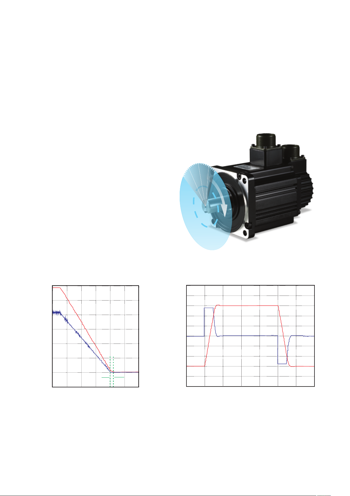
High Positioning Accuracy
►
ECMA series servo motors feature incremental encoders with 20-bit resolution which can eliminate
unstable commands at low speed, smooth motor operation and enhance the accuracy of positioning.
►
Absolute encoder supported. 17-bit motor position will not get lost when power is cut off.
20-bit, incremental encoder /
17-bit, absolute encoder
High Responsiveness
▲
►
Up to 1kHz frequency response.
►
Settling time below 1ms.
►
7ms acceleration time for speeds from -3000 r/min to 3000 r/min with an empty load!
(Note: The test record of a 400W motor with 60mm frame size)
6
5
4
3
2
1
Pulse command
fre quency
0
Postion error & Pulse command freq
-1
0
10
20
Time(ms)
Position error
1ms
30
40
50
60
Speed ( ) & Torque (N-m)r/min
5000
4000
3000
2000
1000
-1000
-2000
-3000
-4000
-5000
0
0
70
10
20
30
Time(ms)
40
50
60 70
3
Page 5
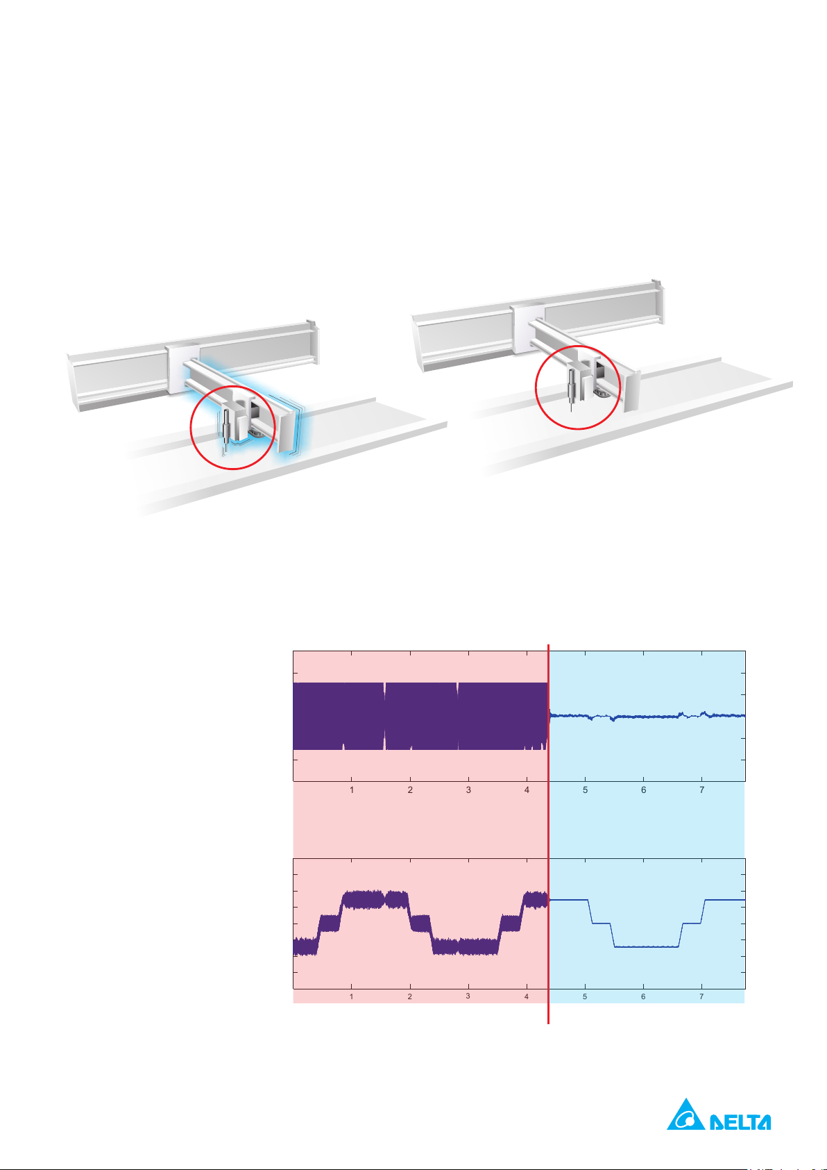
Excellent Suppression Functions
torque (Amp)
Speed (rpm)
t (sec)
t (sec)
►
Vibration Suppression (Low Frequency)
Two vibration suppression filters are provided for long arm system to minimize the vibration at
machine edges effectively.
►
Without Suppression
Function When Settling
Resonance Suppression
(High Frequency)
Two auto notch filters and
one manual notch filter
are provided to suppress
mechanical resonance
efficiently.
With Suppression
Function When Settling
Notch Filter Starts
30
20
10
0
-10
-20
-30
0 1 2 3 4 5 6 7
After SuppressionBefore Suppression
2000
1500
1000
500
-500
-1000
-1500
-2000
0
0
1 2
3
4 5
6 7
4
Page 6
ASDA-A2 Series Features
Full-Closed Loop Control Function*1
►
Reduces the effects of backlash and flexibility from the machine and
ensures the accuracy of positioning.
主編碼器
Motor Encoder
光學尺
Linear Scale
Note:
*1. PT and DMCNET mode only.
CN5
CN2
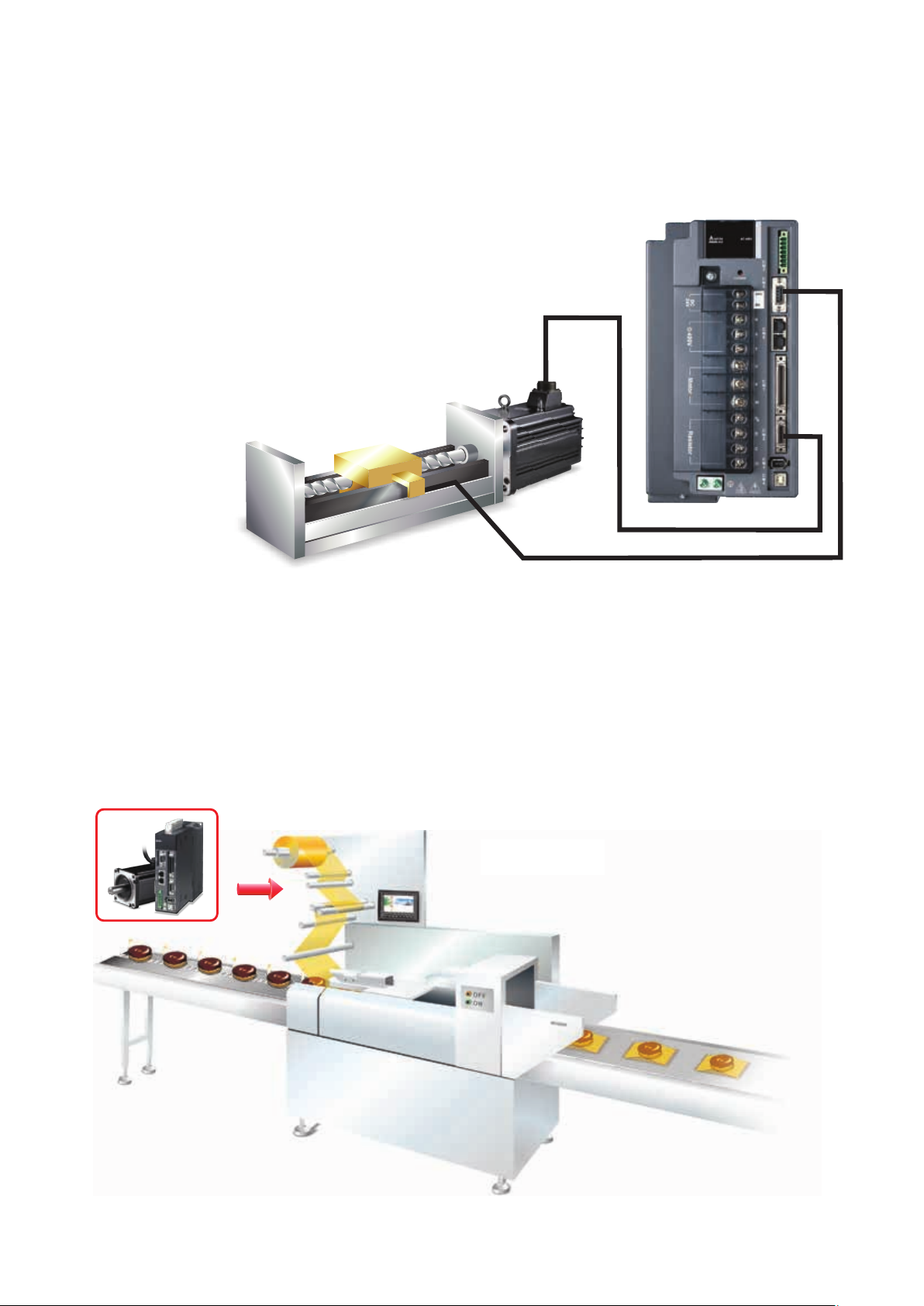
Electronic CAM (E-CAM) Function
►
720 points max. for E-CAM outline.
►
Smooth interpolation between points can be completed automatically to yield a flexible programming.
►
ASDA-Soft configuration software supported.
►
Easy to use for flying shear, rotary cut, and other cam applications.
ASDA-A2 E-CAM 功能於
E-CAM function of ASDA-A2 series
包裝機上的應用
for packaging machines and
packaging lines
5
Page 7

Versatile PR Mode
►
ASDA-Soft configuration software supported.
►
New sub-modes supported, not traditional point-to-point control.
►
64 procedures can be applied.
►
Motion profile can be changed instantaneously.
►
35 Homing modes / Jump mode / Write parameter mode /
Constant speed mode / Position control mode supported.
Speed
Sequential Command
P_Command 1
P_Command 2
Delay 1
A command is executed only when the
previous command is completed.
Speed
Insertion Command
P_Command 2
Time
Speed
Overlap Command
P_Command 2 P_Command 1
Time
The second command is executed after the
delay time or during the deceleration period.
P_Command 1
External command triggered
Insertion changes the command executed at the
moment it is inserted.
Time
6
Page 8
ASDA-A2 Series Features
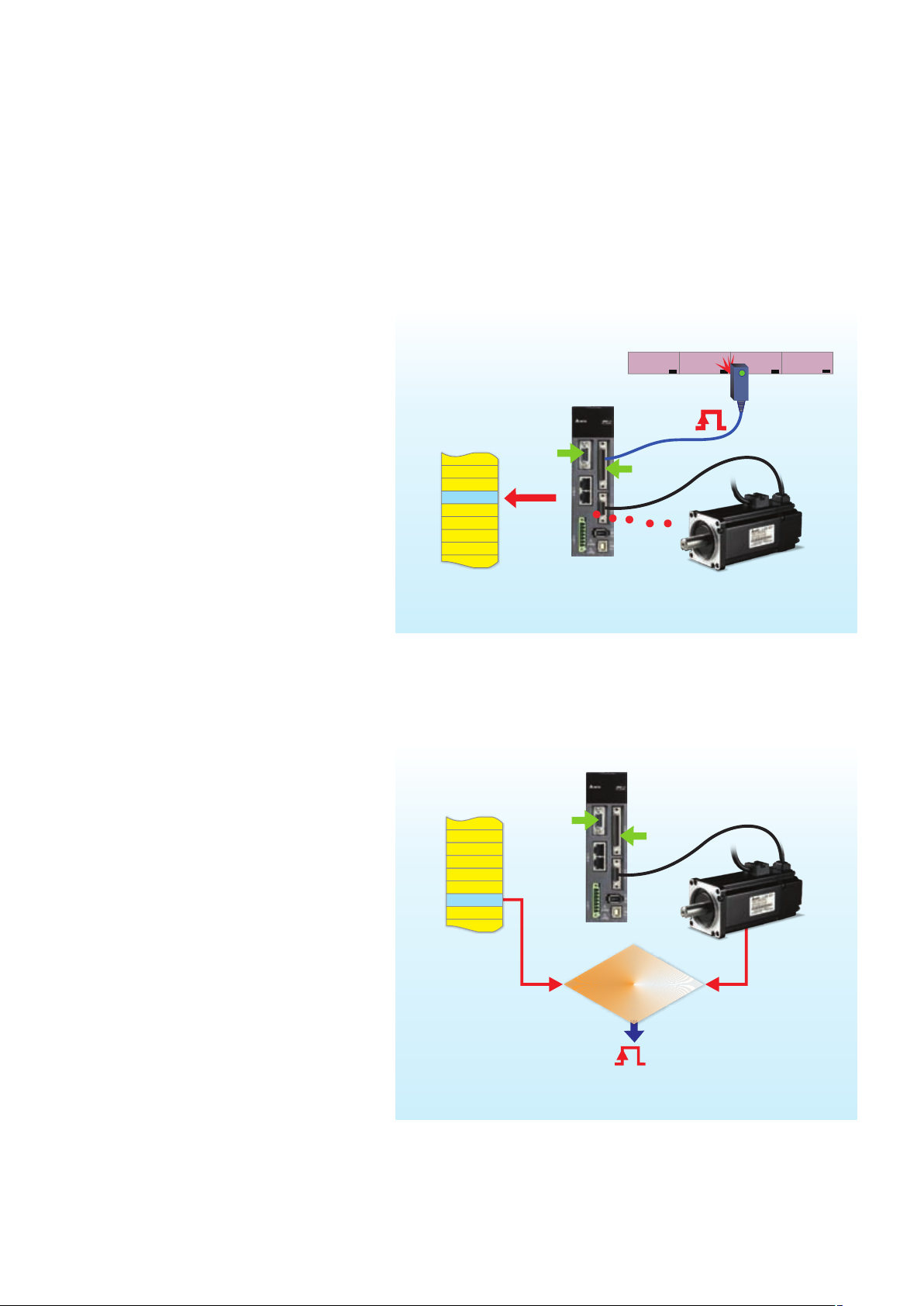
Capture and Compare Functions
Capture - Position Latch Function
►
Latches the coordinate value on the
reference axis.
►
Response time is less than 5us.
►
It can be used to do mark tracing.
►
Maximum 800 records
Data Array
38 3838
When DI7 is triggered, the latched position is
recorded in Data Array.
Linear
Encoder
DI 7
Pulse
Train
383 838
Motor Encoder
Compare - Position Detection
Function
►
Detects the location on the
reference axis.
►
Response time is less than 5us.
►
It can be used for CCD camera
applications.
►
Maximum 800 records
Data Array
383838
When the record in Data Array is the same as the
detected position, DO4 will output.
Linear
Encoder
Posi tion
True
Position
383838
Pulse
Train
==
DO4
Motor Encoder
7
Page 9
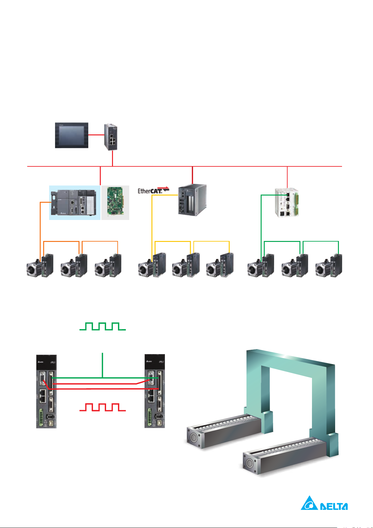
Supports High-Speed DMCNET, EtherCAT, CANopen Protocols for
Multi-Axis Synchronous Control
DOP-B DVS
Ethernet
AH500
PCI-DMC
DMCNET
or
ASDA-A2-F ASDA-A2-E ASDA-A2-M
Integrated Gantry Control
Sent From Host Controller
Axis 1 Axis 2
Pulse Command
CANopen
MH1-S30D DVP-10MC
Position Monitoring
8
Page 10

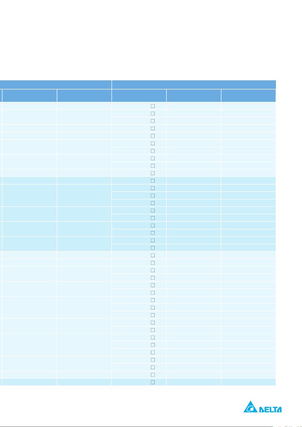
Product Line-up
NOTE
220V Series
Motor Series Phase
Low Inertia ECMA-C 3000 r/min 1-phase / 3-phase
Servo Motors Servo Drives
Rated Output
Power (W)
50 ECMA-C1040F
100 ECMA-C 0401 S 0.90 2.70
200 ECMA-C 0602 S 1.55 4.65 ASD-A2-0221- 1.55 4.65
400 ECMA-C 0604 S 2.60 7.80
400 ECMA-C 0804 7 2.60 7.80
750 ECMA-C 0807 S 5.10 15.30
750 ECMA-C 0907 S 3.66 11.00
1000 ECMA-C 0910 S 4.25 12.37
1000 ECMA-C 1010 S 7.30 21.90
2000 ECMA-C 1020 S 12.05 36.15 ASD-A2-2023- 13.40 40.20
3000 ECMA-C 1330 4 17.2 47.5 ASD-A2-3023- 19.40 58.20
Model Name Rated current (Arms) Maximum current (A) Model Name
S 0.69 2.05
Medium Inertia ECMA-E 2000 r/min 1-phase / 3-phase
Medium-High Inertia ECMA-F 1500 r/min 1-phase / 3-phase
High Inertia ECMA-C/G 3000 r/min 1-phase / 3-phase
500 ECMA-E
1000 ECMA-E 1310 S 5.60 16.80 ASD-A2-1021- 7.30 21.90
1500 ECMA-E 1315 S 8.30 24.90 ASD-A2-1521- 8.66 24.90
2000 ECMA-E 1320 S 11.01 33.03
2000 ECMA-E 1820 S 11.22 33.66
3000 ECMA-E 1830 S 16.10 48.30
3500 ECMA-E 1835 S 19.20 57.60
500 ECMA-F
850 ECMA-F 1308 S 7.10 19.40 ASD-A2-1021- 7.30 21.90
1300 ECMA-F 1313 S 12.60 38.60
1800 ECMA-F 1318 S 13.00 36.00
3000 ECMA-F 1830 S 19.40 58.20 ASD-A2-3023- 19.40 58.20
4500 ECMA-F 1845 S 32.50 81.30
5500 ECMA-F 1855 3 40.00 100.00 ASD-A2-5523- 40.00 106
7500 ECMA-F 1875 3 47.50 118.80 ASD-A2-7523- 47.50 141.1
11000 ECMA-F1221B 3 51.80 129.50 ASD-A2-1B23- 54.40 141.1
15000 ECMA-F1221F S 67 162 ASD-A2-1F23- 70.00 212.2
400 ECMA-C
750 ECMA-C 0807 H 5.10 15.30 ASD-A2-0721- 5.10 15.30
300 ECMA-G 1303 S 2.50 7.50 ASD-A2-0421- 2.60 7.80
600 ECMA-G 1306 S 4.80 14.40 ASD-A2-0721- 5.10 15.30
900 ECMA-G 1309 S 7.50 22.50 ASD-A2-1021- 7.30 21.90
1305 S 2.90 8.70
1305 S 3.90 12.10 ASD-A2-0721- 5.10 15.30
0604 H 2.60 7.80 ASD-A2-0421 2.60 7.80
The boxes (
1)
The boxes (
2)
The boxes (
3)
) at the ends of the servo drive model names are for optional configurations. For the actual model name, please refer to the model explanation of the servo drive.
) in the model names represent encoder type. =1: Incremental encoder, 20-bit; =2: Incremental encoder, 17-bit; ▲ =A: Absolute type
) in the model names represent shaft end/brake or the number of oil seal.
9
Page 11
0.69 2.05
ASD-A2-0121-
Continuous Output
Current (Arms)
0.90 2.70
Max. Instantaneous
Current (A)
ASD-A2-0421-
ASD-A2-0721-
ASD-A2-1021-
2.90 8.70
3.90 12.10 ASD-A2-0721- 5.10 15.30
ASD-A2-0421-
ASD-A2-0721-
ASD-A2-2023-
ASD-A2-3023-
ASD-A2-2023-
2.60 7.80
5.10 15.30
7.30 21.90
2.60 7.80
5.10 15.30
13.40 40.20
19.40 58.20
13.40 40.20
ASD-A2-4523-
ASD-A2-5523-
2.60 7.80 ASD-A2-0421 2.60 7.80
32.50 70.7
40.00 106
10
Page 12

Product Line-up
NOTE
400V Series
Motor Series Phase
Low Inertia ECMA-J 3000 r/min 3-phase
Servo Motors Servo Drives
Rated Output
Power (W)
400 ECMA-J
750 ECMA-J 0807 S 3.07 9.5
750 ECMA-J 0907 S 2.16 6.37 ASD-A2-0743- 3.07 9.21
1000 ECMA-J 0910 S 2.4 7.17 ASD-A2-1043- 3.52 9.86
1000 ECMA-J 1010 S 4.15 12.46
2000 ECMA-J 1020 S 7.09 21.28
3000 ECMA-J 1330 4 9.8 29.99 ASD-A2-3043- 11.9 33.32
750 ECMA-K
1000 ECMA-K 1310 S 3.52 10.56
Model Name Rated current (Arms) Maximum current (A) Model Name
0604 S 1.62 4.85 ASD-A2-0743- 3.07 9.21
1305 S 1.7 5.2 ASD-A2-0743- 3.07 9.21
Medium Inertia ECMA-K 2000 r/min 3-phase
Medium-High Inertia ECMA-L 1500 r/min 3-phase
1500 ECMA-K 1315 S 5.02 15.06
2000 ECMA-K 1320 S 6.66 19.98
2000 ECMA-K 1820 S 6.6 19.88
750 ECMA-L
850 ECMA-L 1308 S 3.4 8.85 ASD-A2-1043- 3.52 9.86
1300 ECMA-L 1313 S 5.02 15
3000 ECMA-L 1830 S 11.53 34.6
4500 ECMA-L 1845 S 20.8 52
5500 ECMA-L 1855 3 22.37 56
7500 ECMA-L 1875 3 27.3 68.3
1305 S 2.1 6.1 ASD-A2-0743- 3.07 9.21
11000 ECMA-L1221B 3 27.2 68
15000 ECMA-L1221F 3 41.6 100 ASD-A2-1F43- 38.65 85.03
High Inertia ECMA-M 3000 r/min 3-phase 900 ECMA-M 1309 S 4.4 13.1 ASD-A2-1543- 5.02 10.04
The boxes (
1)
2) The boxes ( ) in the model names represent encoder type. =1: Incremental encoder, 20-bit ; =2: Incremental encoder, 17-bit; =A: Absolute type
The boxes (
3)
) at the ends of the servo drive model names are for optional configurations. For the actual model name, please refer to the model explanation of the servo drive.
) in the model names represent shaft end/brake or the number of oil seal.
11
Page 13
Continuous Output
Current (Arms)
1.62 4.85 ASD-A2-0743- 3.07 9.21
ASD-A2-0743-
ASD-A2-1043-
3.07 9.21
3.52 9.86
Max. Instantaneous
Current (A)
ASD-A2-1543-
ASD-A2-2043-
ASD-A2-2043-
ASD-A2-3043-
1.7 5.2 ASD-A2-0743- 3.07 9.21
ASD-A2-1043-
ASD-A2-1543-
ASD-A2-2043-
ASD-A2-1543-
ASD-A2-2043-
ASD-A2-2043-
ASD-A2-3043-
ASD-A2-2043-
ASD-A2-3043-
2.1 6.1 ASD-A2-0743- 3.07 9.21
ASD-A2-1543-
ASD-A2-2043-
ASD-A2-3043-
ASD-A2-4543-
ASD-A2-4543-
ASD-A2-5543-
ASD-A2-7543-
ASD-A2-5543-
ASD-A2-7543-
ASD-A2-7543-
ASD-A2-1B43-
ASD-A2-1F43-
ASD-A2-1B43-
ASD-A2-1F43-
5.02 10.04
6.66 18.65
6.66 18.65
11.9 33.2
3.52 9.86
5.02 10.04
6.66 18.65
5.02 10.04
6.66 18.65
6.66 18.65
11.9 33.32
6.66 18.65
11.9 33.32
5.02 10.04
6.66 18.65
11.9 33.32
20 44
20 44
22.04 48.49
28.39 62.46
22.04 48.49
28.39 62.46
28.39 62.46
28.1 61.82
38.65 85.03
28.1 61.82
38.65 85.03
12
Page 14
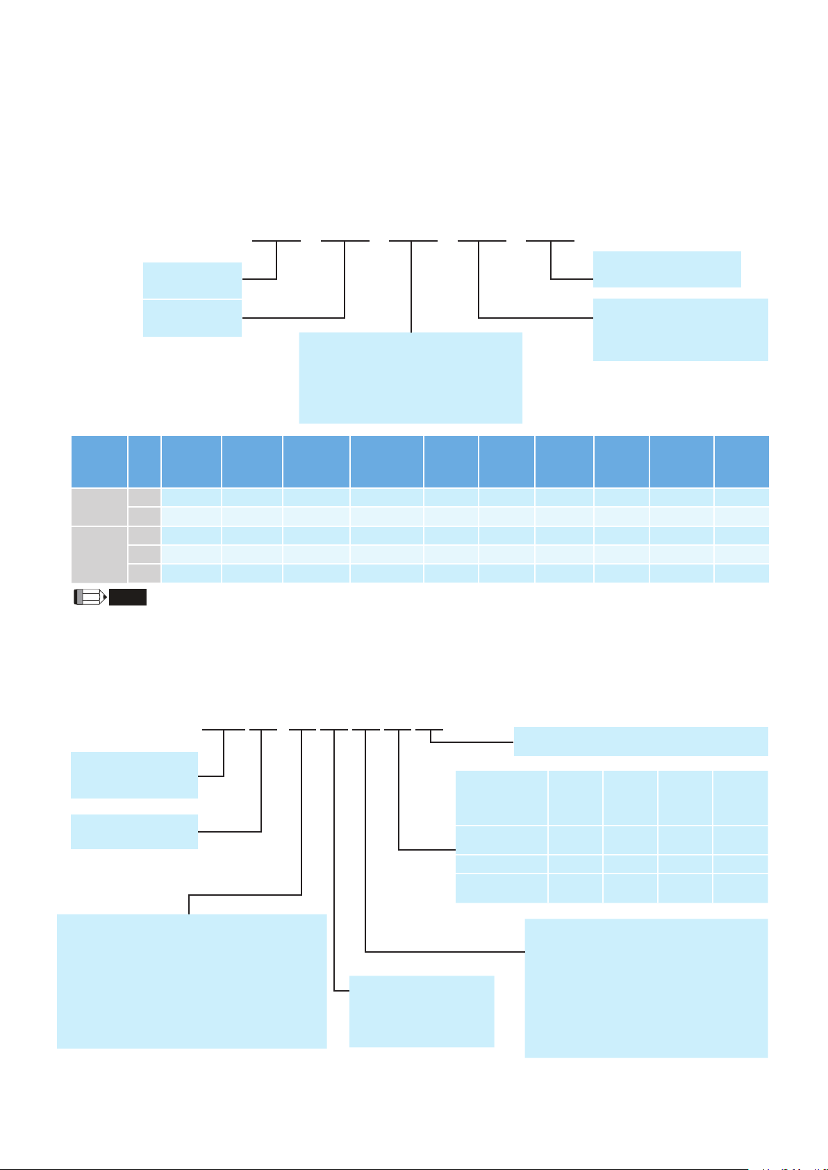
Model Explanation
NOTE
ASDA-A2 Series Servo Drives
ASD - A2*5- 04 21 - M
Product Name:
AC Servo Drive
Series:
A2
Rated Output Power
01: 100 W
02: 200 W
04: 400 W
07: 750 W
10: 1 kW
15: 1.5 kW
20: 2 kW
30: 3 kW
45: 4.5 kW
55: 5.5 kW
75: 7.5 kW
1B: 11 kW
Model Type
(see the table below)
Input Voltage and Phase
21: 220V 1-phase / 3-phase
23: 220V 3-phase
43: 400V 3-phase
1F: 15 kW
Standard
Model
Type
RS-485
(CN3)
Full-Closed
Control
(CN5)
*1
Extension
Port for
Digital Input
(CN7)
EtherCAT *4CANpen DMCNET
L ○ ○ X X X X ○ ○ ○ X
U ○ ○ ○ X X X ○ ○ ○ ○
Analog
Voltage
Control
Pulse
Input Port
E X X ○ ○ X X X X ○ X
Network
Model
F ○ ○ X X X ○ X X ○
M ○ ○ X X ○ X ○ ○ ○ ○
2. When applying communication mode (A2-E, -F, -M models), PR parameters can be read and written through DMCNET only.
3. E-CAM function can only be used in PR mode.
4. For information about ASDA A2-E EtherCAT interface servo drive, please refer to the ASDA A2-E brochure.
5. For communication mode -F/-M models with 400V/11kW, 15kW is categorized as ASDA-A2R.
6. Rated power of 100W to 1.5kW are marked number 21 with 220V, single-phase and three-phase connections
1. In PR mode, only A2-F supports full-closed control function.
PR
Parameters
*2
*6
E-CAM
X
*3
ECMA Series Servo Motors
ECM A - C1 06 02 E S
Product Nam
ECM: Electrical
Commutation Motor
Driving Type
A: AC Servo Motor
Series
Rated Voltage / Rated Speed
C: 220V / 3000 r/min
E: 220V / 2000 r/min
F: 220V / 1500 r/min
G: 220V / 1000 r/min
Encoder Type
1: Incremental encoder, 20-bit
2: Incremental encoder, 17-bit
3: 2500 ppr
e
J: 400V / 3000 r/min
K: 400V / 2000 r/min
L: 400V / 1500 r/min
M: 400V / 1000 r/min
A: Absolute encoder,
Single-turn: 17-bit
Multi-turn: 16-bit
Motor Frame Size
04: 40 mm
06: 60 mm
08: 80 mm
09: 86 mm
Shaft Type and
(with screw hole)
Keyway (with
10: 100 mm
13: 130 mm
18: 180 mm
22: 220 mm
S: Standard Shaft Diameter
H: High Inertia Model
W/O
Brake
Oil Seal
Round Shaft
Keyway E F - -
screw hole)
W/O Oil
Seal
- - C D
P Q R S
Rated Output Power
0F: 50 W
01: 100 W
02: 200 W
03: 300 W
04: 400 W
05: 500 W
06: 600 W
07: 750 W
With
Brake
W/O Oil
Seal
08: 850 W
09: 900 W
10: 1 kW
13: 1.3 kW
15: 1.5 kW
18: 1.8 kW
20: 2 kW
30: 3 kW
W/O
Brake
With
Oil Seal
35: 3.5 kW
45: 4.5 kW
50: 5.0 kW
55: 5.5 kW
75: 7.5 kW
1B: 11 kW
1F: 15 kW
With
Brake
With
Oil Seal
13
Page 15
Servo Motor Features
ECMA
ASDA-A2 220V series AC servo drives from 50 W to 15 kW and 380V to 480V ASDA-A2 400V series
AC servo drives from 750 W to 7.5 kW.
For the 220V series, there are 40 mm, 60 mm, 80 mm, 86 mm, 100 mm, 130 mm, 180 mm, and 200 mm
eight kinds of frame sizes available. The motor speed is from 1000 r/min to 5000 r/min and the torque
output is from 0.477 N-m to 224 N-m.
For the 400V series, there are 60 mm, 80 mm, 86 mm, 100 mm, 130 mm, 180 mm, six kinds of frame
sizes available. The motor speed is from 1500 r/min to 5000 r/min and the torque output is from 3.82
N-m to 119.36 N-m In terms of optional configurations, ECMA series provides brake and oil seal to fully
support our customers' needs. It also offers two different shaft selections, round shaft and keyway, for
various applications.
series servo motors are permanent AC servo motors, capable of combining with 200 to 230V
14
Page 16

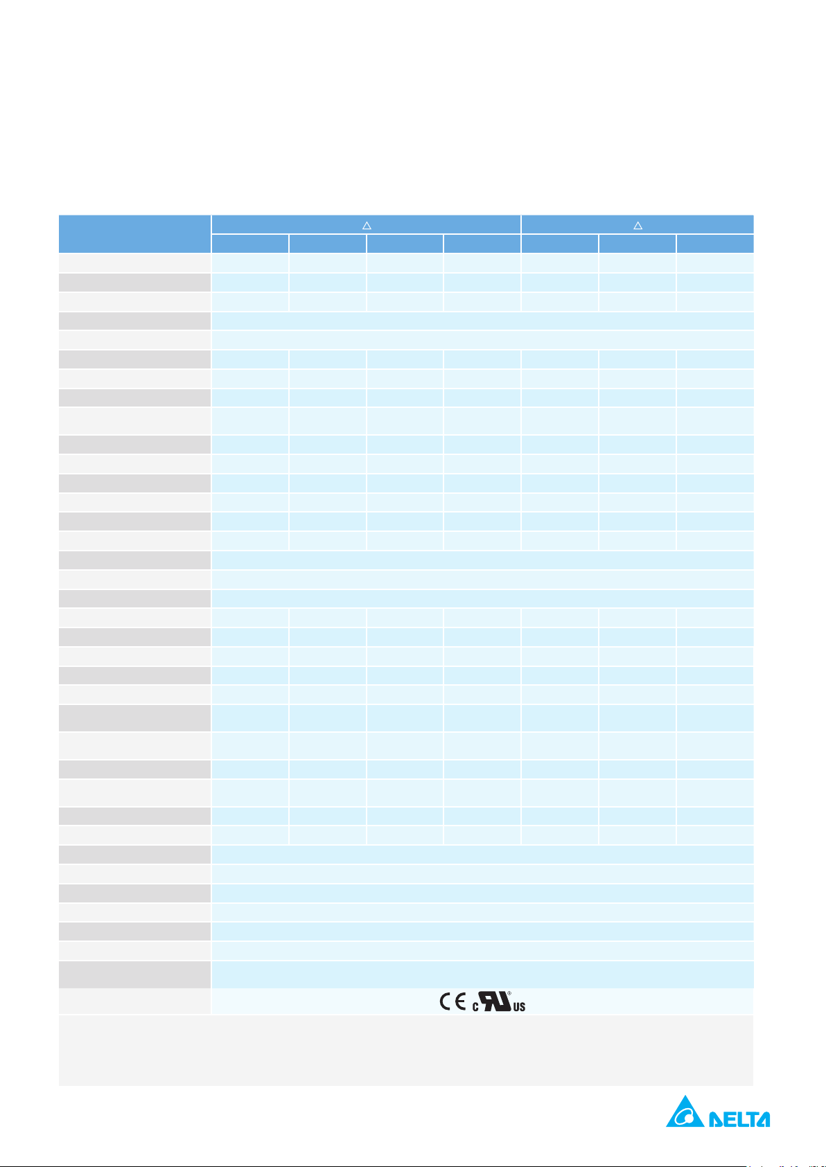
Servo Motor Specifications
Low Inertia Series- 220V Series
ECMA Series
C104 C
0F 01 02 04□S 04 07 07 10 10 20 30
04 C 06 C 08 C 09 C 10 C 13
Rated output power (kW) 0.05 0.1 0.2 0.4 0.4 0.75 0.75 1.0 1.0 2.0 3.0
Rated torque (N-m)
*1
0.159 0.32 0.64 1.27 1.27 2.39 2.39 3.18 3.18 6.37 9.55
Maximum torque (N-m) 0.477 0.96 1.92 3.82 3.82 7.16 7.14 8.78 9.54 19.11 28.65
Rated speed (r/min) 3000 3000 3000 3000
Maximum speed (r/min) 5000 3000 5000 4500
Rated current (A) 0.69 0.90 1.55 2.6 2.6 5.1 3.66 4.25 7.3 12.05 17.2
Maximum current (A) 2.05 2.70 4.65 7.8 7.8 15.3 11 12.37 21.9 36.15 47.5
Power rating (kW/s) 12.27 27.7 22.4 57.6 24.0 50.4 29.6 38.6 38.1 90.6 71.8
Rotor moment of inertia
-4
(x10
kg-m2)
0.0206 0.037 0.177 0.277 0.68 1.13 1.93 2.62 2.65 4.45 12.7
Mechanical time constant (ms) 1.2 0.75 0.80 0.53 0.74 0.63 1.72 1.20 0.74 0.61 1.11
Torque constant-KT (N-m/A) 0.23 0.36 0.41 0.49 0.49 0.47 0.65 0.75 0.44 0.53 0.557
Voltage constant-KE (mV/(r/min) 9.8 13.6 16 17.4 18.5 17.2 24.2 27.5 16.8 19.2 20.98
Armature resistance (Ohm) 12.7 9.30 2.79 1.55 0.93 0.42 1.34 0.897 0.20 0.13 0.0976
Armature inductance (mH) 26 24.0 12.07 6.71 7.39 3.53 7.55 5.7 1.81 1.50 1.21
Electrical time constant (ms) 2.05 2.58 4.3 4.3 7.96 8.36 5.66 6.35 9.3 11.4 12.4
Insulation class Class A (UL), Class B (CE)
Insulation resistance 100MΩ , DC 500V above
Insulation strength 1.8k Vac,1 sec
Weight (kg)(without brake) 0.42 0.5 1.2 1.6 2.1 3.0 2.9 3.8 4.3 6.2 7.8
Weight (kg)(with brake) -- 0.8 1.5 2.0 2.9 3.8 3.69 5.5 4.7 7.2 9.2
Max. radial shaft load (N) 78.4 78.4 196 196 245 245 245 245 490 490 490
Max. thrust shaft load (N) 39.2 39.2 68 68 98 98 98 98 98 98 98
Power rating (kW/s)(with brake) -- 25.6 21.3 53.8 22.1 48.4 29.3 37.9 30.4 82 65.1
Rotor moment of inertia
-4
(x10
kg-m2)(with brake)
Mechanical time constant
(ms)(with brake)
Brake holding torque [Nt-m (min)]
Brake power consumption
(at 20˚C)[W]
-- 0.04 0.19 0.30 0.73 1.18 1.95 2.67 3.33 4.95 14.0
-- 0.81 0.85 0.57 0.78 0.65 1.74 1.22 0.93 0.66 1.22
*2
-- 0.3 1.3 1.3 2.5 2.5 2.5 2.5 8 8 10.0
-- 7.3 6.5 6.5 8.2 8.2 8.2 8.2 18.7 18.7 19.0
Brake release time [ms (Max)] -- 5 10 10 10 10 10 10 10 10 10
Brake pull-in time [ms (Max)] -- 25 70 70 70 70 70 70 70 70 70
Vibration grade (μm) 15
Operating temperature (˚C) 0ºC to 40ºC
Storage temperature (˚C) -10ºC to 80ºC
Operating humidity 20 to 90%RH (non-condensing)
Storage humidity 20 to 90%RH (non-condensing)
Vibration capacity 2.5G
IP Rating
IP65 (when waterproof connectors are used, or when an oil seal is used to be fitted to
the rotating shaft (an oil seal model is used))
Approvals
*1. Rate torque values are continuous permissible values at 0 ~ 40˚C ambient temperature when attaching with the sizes of heatsinks listed below:
ECMA-_ _ 04 / 06 / 08: 250 mm x 250 mm x 6 mm
ECMA-_ _ 10: 300 mm x 300 mm x 12 mm
ECMA-_ _ 13: 400 mm x 400 mm x 20 mm
ECMA-_ _ 18: 550 mm x 550 mm x 30 mm
ECMA-_ _ 22: 650 mm x 650 mm x 35 mm
Material type : Aluminum – F40, F60, F80, F100, F130, F180, F220
*2. The holding brake is used to hold the motor shaft, not for braking the rotation. Never use it for decelerating or stopping the machine.
15
Page 17
Medium Series- 220V Series
13 E 18
ECMA Series
05 10 15 20 20 30 35
Rated output power (kW) 0.5 1.0 1.5 2.0 2.0 3.0 3.5
Rated torque (N-m)
*1
2.39 4.77 7.16 9.55 9.55 14.32 16.71
Maximum torque (N-m) 7.16 14.3 21.48 28.65 28.65 42.97 50.13
Rated speed (r/min) 2000
Maximum speed (r/min) 3000
Rated current (A) 2.9 5.6 8.3 11.01 11.22 16.1 19.2
Maximum current (A) 8.7 16.8 24.9 33.03 33.66 48.3 57.6
Power rating (kW/s) 7.0 27.1 45.9 62.5 26.3 37.3 50.8
Rotor moment of inertia
-4
(x10
kg-m2)(without brake)
8.17 8.41 11.18 14.59 34.68 54.95 54.95
Mechanical time constant (ms) 1.91 1.51 1.10 0.96 1.62 1.06 1.08
Torque constant-KT (N-m/A) 0.83 0.85 0.87 0.87 0.85 0.89 0.87
Voltage constant-KE (mV/(r/min) 30.9 31.9 31.8 31.8 31.4 32.0 32
Armature resistance (Ohm) 0.57 0.47 0.26 0.174 0.119 0.052 0.052
Armature inductance (mH) 7.39 5.99 4.01 2.76 2.84 1.38 1.38
Electrical time constant (ms) 12.96 12.88 15.31 15.86 23.87 26.39 26.39
Insulation class Class A (UL), Class B (CE)
Insulation resistance 100MΩ , DC 500V above
Insulation strength 1.8k Vac,1 sec
Weight (kg)(without brake) 6.8 7.0 7.5 7.8 13.5 18.5 18.5
Weight (kg)(with brake) 8.2 8.4 8.9 9.2 17.5 22.5 22.5
Max. radial shaft load (N) 490 490 490 490 1176 1470 1470
Max. thrust shaft load (N) 98 98 98 98 490 490 490
Power rating (kW/s)(with brake) 6.4 24.9 43.1 57.4 24.1 35.9 48.9
Rotor moment of inertia
-4
(x10
kg-m2)(with brake)
Mechanical time constant
(ms)(with brake)
Brake holding torque [Nt-m (min)]
Brake power consumption
(at 20˚C)[W]
8.94 9.14 11.90 15.88 37.86 57.06 57.06
2.07 1.64 1.19 1.05 1.77 1.10 1.12
*2
10.0 10.0 10.0 10.0 25.0 25.0 25.0
19.0 19.0 19.0 19.0 20.4 20.4 20.4
Brake release time [ms (Max)] 10 10 10 10 10 10 10
Brake pull-in time [ms (Max)] 70 70 70 70 70 70 70
Vibration grade (μm) 15
Operating temperature (˚C) 0ºC to 40ºC
Storage temperature (˚C) -10ºC to 80ºC
Operating humidity 20 to 90%RH (non-condensing)
Storage humidity 20 to 90%RH (non-condensing)
Vibration capacity 2.5G
IP Rating
IP65 (when waterproof connectors are used, or when an oil seal is used to be fitted to
Approvals
*1. Rate torque values are continuous permissible values at 0 ~ 40˚C ambient temperature when attaching with the sizes of heatsinks listed below:
ECMA-_ _ 04 / 06 / 08: 250 mm x 250 mm x 6 mm
ECMA-_ _ 10: 300 mm x 300 mm x 12 mm
ECMA-_ _ 13: 400 mm x 400 mm x 20 mm
ECMA-_ _ 18: 550 mm x 550 mm x 30 mm
ECMA-_ _ 22: 650 mm x 650 mm x 35 mm
Material type : Aluminum – F40, F60, F80, F100, F130, F180, F220
*2. The holding brake is used to hold the motor shaft, not for braking the rotation. Never use it for decelerating or stopping the machine.
E
the rotating shaft (an oil seal model is used))
16
Page 18

Servo Motor Specifications
Medium-High Inertia Series- 220V Series
13 F 18 F122
ECMA Series
05 08 13 18 30 45 55 75 1B 1F
Rated output power (kW) 0.5 0.85 1.3 1.8 3.0 4.5 5.5 7.5 11 15
Rated torque (N-m)
*1
3.18 5.41 8.34 11.48 19.10 28.65 35.01 47.74 70 95.4
Maximum torque (N-m) 8.92 13.8 23.3 28.7 57.29 71.62 87.53 119.36 175 224.0
Rated speed (r/min) 1500
Maximum speed (r/min) 3000 2000
Rated current (A) 3.9 7.1 12.6 13 19.4 32.5 40.0 47.5 51.8 67
Maximum current (A) 12.1 19.4 38.6 36 58.2 81.3 100.0 118.8 129.5 162
Power rating (kW/s) 9.8 21.52 34.78 52.93 66.4 105.5 122.9 159.7 144.9 201.8
Rotor moment of inertia
-4
(x10
kg-m2)(without brake)
10.3 13.6 20 24.9 54.95 77.75 99.78 142.7 338 451
Mechanical time constant (ms) 2.8 2.43 1.62 1.7 1.28 0.92 0.96 0.63 1.38 1.23
Torque constant-KT (N-m/A) 0.82 0.76 0.66 0.88 0.98 0.88 0.88 1.01 1.37 1.42
Voltage constant-KE (mV/(r/min) 29.5 29.2 24.2 32.2 35.0 32.0 31.0 35.5 49 50
Armature resistance (Ohm) 0.624 0.38 0.124 0.185 0.077 0.032 0.025 0.015 0.026 0.0184
Armature inductance (mH) 7 4.77 1.7 2.6 1.27 0.89 0.60 0.40 0.65 0.48
Electrical time constant (ms) 11.22 12.55 13.71 14.05 16.5 27.8 24.0 26.7 24.79 26.09
Insulation class Class A (UL), Class B (CE)
Insulation resistance 100MΩ , DC 500V above
Insulation strength 1.8k Vac,1 sec
Weight (kg)(without brake) 6.3 8.6 9.4 10.5 18.5 23.5 30.5 40.5 56.4 75
Weight (kg)(with brake) 7.7 10.0 10.8 11.9 22.5 29 36 46 68.4 87
Max. radial shaft load (N) 490 490 490 490 1470 1470 1764 1764 3300 3300
Max. thrust shaft load (N) 98 98 98 98 490 490 588 588 1100 1100
Power rating (kW/s)(with brake) 8.8 19.78 32.66 50.3 63.9 101.8 119.4 156.6 141.4 197.1
Rotor moment of inertia
-4
(x10
kg-m2)(with brake)
Mechanical time constant
(ms)(with brake)
Brake holding torque[Nt-m(min)]
Brake power consumption
(at 20˚C)[W]
11.5 14.8 21.3 26.2 57.06 80.65 102.70 145.55 346.5 461.8
3.12 2.65 1.73 1.79 1.33 0.96 0.99 0.64 1.41 1.25
*2
10 10.0 10.0 10.0 25.0 55.0 55.0 55.0 115 11 5
19 19.0 19.0 19.0 20.4 19.9 19.9 19.9 28.8 28.8
Brake release time [ms (Max)] 10 10 10 10 10 10 10 10 10 10
Brake pull-in time [ms (Max)] 70 70 70 70 70 70 70 70 70 70
Vibration grade (μm) 15
Operating temperature (˚C) 0ºC to 40ºC
Storage temperature (˚C) -10ºC to 80ºC
Operating humidity 20 to 90%RH (non-condensing)
Storage humidity 20 to 90%RH (non-condensing)
Vibration capacity 2.5G
IP Rating
Approvals
*1. Rate torque values are continuous permissible values at 0 ~ 40˚C ambient temperature when attaching with the sizes of heatsinks listed below:
ECMA-_ _ 04 / 06 / 08: 250 mm x 250 mm x 6 mm
ECMA-_ _ 10: 300 mm x 300 mm x 12 mm
ECMA-_ _ 13: 400 mm x 400 mm x 20 mm
ECMA-_ _ 18: 550 mm x 550 mm x 30 mm
ECMA-_ _ 22: 650 mm x 650 mm x 35 mm
Material type : Aluminum – F40, F60, F80, F100, F130, F180, F220
*2. The holding brake is used to hold the motor shaft, not for braking the rotation. Never use it for decelerating or stopping the machine.
F
IP65 (when waterproof connectors are used, or when an oil seal is used to be fitted to
the rotating shaft (an oil seal model is used))
17
Page 19

High Inertia Series- 220V Series
06 C 08 G 13
ECMA Series
Rated output power (kW) 0.4 0.75 0.3 0.6 0.9
Rated torque (N-m)
Maximum torque (N-m) 3.82 7.16 8.59 17.19 21.48
Rated speed (r/min) 3000 1000
Maximum speed (r/min) 5000 2000
Rated current (A) 2.6 5.1 2.5 4.8 7.5
Maximum current (A) 7.8 15.3 7.5 14.4 22.5
Power rating (kW/s) 21.7 19.63 10.0 39.0 66.0
Rotor moment of inertia
-4
(x10
kg-m2)(without brake)
Mechanical time constant (ms) 1.42 1.6 1.84 1.40 1.06
Torque constant-KT (N-m/A) 0.49 0.47 1.15 1.19 1.15
Voltage constant-KE (mV/(r/min) 17.4 17.2 42.5 43.8 41.6
Armature resistance (Ohm) 1.55 0.42 1.06 0.82 0.43
Armature inductance (mH) 6.71 3.53 14.29 11.12 6.97
Electrical time constant (ms) 4.3 8.36 13.5 13.50 16.06
Insulation class Class A (UL), Class B (CE)
Insulation resistance
Insulation strength 1.8k Vac,1 sec
Weight (kg)(without brake) 1.8 3.4 6.8 7.0 7.5
Weight (kg)(with brake) 2.2 3.9 8.2 8.4 8.9
Max. radial shaft load (N) 196 245 490 490 490
Max. thrust shaft load (N) 68 98 98 98 98
Power rating (kW/s)(with brake) 21.48 19.3 9.2 35.9 62.1
Rotor moment of inertia
-4
(x10
kg-m2)(with brake)
Mechanical time constant
(ms)(with brake)
Brake holding torque [Nt-m (min)]
Brake power consumption
(at 20˚C)[W]
Brake release time [ms (Max)] 10 10 10 10 10
Brake pull-in time [ms (Max)] 70 70 70 70 70
Vibration grade (μm) 15
Operating temperature (˚C) 0ºC to 40ºC
Storage temperature (˚C) -10ºC to 80ºC
Operating humidity 20 to 90%RH (non-condensing)
Storage humidity 20 to 90%RH (non-condensing)
Vibration capacity 2.5G
IP Rating
Approvals
*1. Rate torque values are continuous permissible values at 0 ~ 40˚C ambient temperature when attaching with the sizes of heatsinks listed below:
ECMA-_ _ 04 / 06 / 08: 250 mm x 250 mm x 6 mm
ECMA-_ _ 10: 300 mm x 300 mm x 12 mm
ECMA-_ _ 13: 400 mm x 400 mm x 20 mm
ECMA-_ _ 18: 550 mm x 550 mm x 30 mm
ECMA-_ _ 22: 650 mm x 650 mm x 35 mm
Material type : Aluminum – F40, F60, F80, F100, F130, F180, F220
*2. The holding brake is used to hold the motor shaft, not for braking the rotation. Never use it for decelerating or stopping the machine.
*1
*2
C
▅
04
H 07▅H 03 06 09
1.27 2.39 2.86 5.73 8.59
0.743 2.91 8.17 8.41 11.18
100M
, DC 500V
Ω
0.751 2.96 8.94 9.14 11.9
1.43 1.62 2.0 1.51 1.13
1.3 2.5 10.0 10.0 10.0
6.5 8.2 19.0 19.0 19.0
IP65 (when waterproof connectors are used, or when an oil seal is used to be fitted to
the rotating shaft (an oil seal model is used))
above
18
Page 20

Servo Motor Specifications
Low / Medium Series- 400V Series
06 J 08 J 09 J 10 J 13 K 13 K 18
ECMA Series
Rated output power (kW) 0.4 0.75 0.75 1 1.0 2.0 3.0 0.5 1.0 1.5 2.0 2.0
Rated torque (N-m)
Maximum torque (N-m) 3.82 7.16 7.14 8.78 9.54 19.1 28.65 7.16 14.32 21.48 28.65 28.65
Rated speed (r/min) 3000 3000 3000 3000 2000
Maximum speed (r/min) 5000 3000 5000 4500 3000
Rated current (A) 1.62 3.07 2.16 2.4 4.15 7.09 9.8 1.7 3.52 5.02 6.66 6.6
Maximum current (A) 4.85 9.5 6.37 7.17 12.46 21.28 29.99 5.2 10.56 15.06 19.98 19.88
Power rating (kW/s) 58.2 50.4 29.6 38.6 38.2 91.2 71.8 6.99 27.1 45.9 62.5 26.3
Rotor moment of inertia
-4
(x10
kg-m2)(without brake)
Mechanical time constant (ms) 0.47 0.66 1.56 1.06 0.77 0.58 0.99 2.08 1.80 1.24 1.04 1.74
Torque constant-KT (N-m/A) 0.79 0.78 1.12 1.29 0.77 0.9 0.97 1.41 1.35 1.43 1.43 1.45
Voltage constant-KE (mV/(r/min) 30.6 28.24 42 50.9 29.0 34.4 37.3 51.5 53.2 55 55 54.0
Armature resistance (Ohm) 3.95 1.22 3.62 2.58 0.617 0.388 0.269 1.76 1.47 0.83 0.57 0.376
Armature inductance (mH) 21.3 10.68 21.2 15.28 6.03 4.62 3.55 22.4 17.79 11.67 8.29 7.87
Electrical time constant (ms) 5.39 8.75 5.85 5.93 9.77 11.9 13.2 12.73 12.04 14.04 14.39 20.9
Insulation class Class A (UL), Class B (CE)
Insulation resistance 100MΩ, DC 500V above
Insulation strength 2.3k Vac, 1 sec
Weight (kg)(without brake) 1.6 3.0 2.9 3.8 4.3 6.2 7.8 6.8 7.0 7.5 7.8 13.5
Weight (kg)(with brake) 2 3.8 - - 4.7 7.2 9.2 8.2 8.4 8.9 9.2 17.5
Max. radial shaft load (N) 19.6 245 245 245 490 490 490 490 490 490 490 1176
Max. thrust shaft load (N) 68 98 98 98 98 98 98 98 98 98 98 490
Power rating (kW/s)(with brake) 53.8 48.4 29.3 37.9 30.4 82 65.1 6.39 24.9 43.1 59.7 24.1
Rotor moment of inertia
-4
(x10
kg-m2)(with brake)
Mechanical time constant
(ms)(with brake)
Brake holding torque [Nt-m (min)]*21.3 2.5 2.5 2.5 8.0 8.0 10.0 10.0 10.0 10.0 10.0 25.0
Brake power consumption
(at 20˚C)[W]
Brake release time [ms (Max)] 10 10 10 10 10 10 10 10 10 10 10 10
Brake pull-in time [ms (Max)] 70 70 70 70 70 70 70 70 70 70 70 70
Vibration grade (μm) 15
Operating temperature (˚C) 0ºC to 40ºC
Storage temperature (˚C) -10ºC to 80ºC
Operating humidity 20 to 90%RH (non-condensing)
Storage humidity 20 to 90%RH (non-condensing)
Vibration capacity 2.5G
IP Rating
Approvals
*1. Rate torque values are continuous permissible values at 0 ~ 40˚C ambient temperature when attaching with the sizes of heatsinks listed below:
ECMA-_ _ 08: 250 mm x 250 mm x 6 mm
ECMA-_ _ 13: 400 mm x 400 mm x 20 mm
ECMA-_ _ 18: 550 mm x 550 mm x 30 mm
Material type : Aluminum – F80, F130, F180, F220
*2. The holding brake is used to hold the motor shaft, not for braking the rotation. Never use it for decelerating or stopping the machine.
*1
J
04 07 07 10 10 20 30 05 10 15 20 20
1.27 2.39 2.39 3.18 3.18 6.37 9.55 2.39 4.77 7.16 9.55 9.55
0.277 1.13 1.93 2.62 2.65 4.45 12.7 8.17 8.41 11.18 14.59 34.68
0.3 1.18 1.95 2.67 3.33 4.95 14.0 8.94 9.14 11.90 15.88 37.86
0.52 0.65 1.57 1.08 0.96 0.65 1.09 2.28 1.96 1.32 1.13 1.9
6.5 8.5 8.2 8.2 18.5 18.5 19.0 19.0 19.0 19.0 19.0 20.4
IP65 (when waterproof connectors are used, or when an oil seal is used to be fitted to
the rotating shaft (an oil seal model is used))
19
Page 21

Medium-High / High Inertia Series- 400V Series
13 L 18 L122 M 13
ECMA Series
05 08 13 30 45 55 75 1B 1F 09
Rated output power (kW) 0.5 0.85 1.3 3.0 4.5 5.5 7.5 11 15 0.9
Rated torque (N-m)
*1
3.18 5.39 8.34 19.10 28.65 35.0 47.74 70 95.4 8.59
Maximum torque (N-m) 8.92 13.8 23.3 57.29 71.62 87.53 119.36 175 224 21.48
Rated speed (r/min) 1500 1500 1000
Maximum speed (r/min) 3000 2000 2000
Rated current (A) 2.1 3.4 5.02 11.53 20.8 22.37 27.3 27.2 41.6 4.4
Maximum current (A) 6.1 8.85 15 34.6 52 56 68.3 68 100 13.1
Power rating (kW/s) 7.72 17.0 29.47 66.4 105.5 122.9 159.7 145 201.8 66
Rotor moment of inertia
-4
(x10
kg-m2)(without brake)
13.1 17.1 23.6 54.95 77.75 99.78 142.7 338 451 11.18
Mechanical time constant (ms) 2.3 1.76 1.44 1.11 0.94 0.88 0.77 1.42 1.34 1.21
Torque constant-KT (N-m/A) 1.5 1.59 1.66 1.66 1.38 1.56 1.75 2.57 2.29 1.95
Voltage constant-KE (mV/(r/min) 55.5 58.9 61.1 64.4 53 58.9 66.4 96 83.9 71.7
Armature resistance (Ohm) 1.41 0.92 0.59 0.21 0.09 0.07 0.06 0.0994 0.0545 1.45
Armature inductance (mH) 20 14.1 9.54 4.94 2.36 2.2 1.7 2.51 1.43 23.3
Electrical time constant (ms) 14.1 15.33 16.17 23.97 28.07 27.6 28.29 25.25 26.26 16.07
Insulation class Class A (UL), Class B (CE)
Insulation resistance 100MΩ, DC 500V above
Insulation strength 2.3k Vac,1 sec
Weight (kg)(without brake) 6.8 8.6 10.7 18.5 23.5 30.5 40.5 56.4 75 7.5
Weight (kg)(with brake) - 10 -- 22.5 29 36 46 68.4 87 8.9
Max. radial shaft load (N) 490 490 490 1470 1470 1764 1764 3300 3300 490
Max. thrust shaft load (N) 98 98 98 490 490 588 588 1100 1100 98
Power rating (kW/s)(with brake) 7.02 14.82 27.82 63.9 101.8 119.4 156.6 141.4 197.1 62
Rotor moment of inertia
-4
(x10
kg-m2)(with brake)
Mechanical time constant
(ms)(with brake)
14.4 19.6 25 57.06 80.65 102.70 145.5 346.5 461.8 11.9
2.54 2.02 1.52 1.16 0.95 0.91 0.79 1.46 1.37 1.29
Brake holding torque [Nt-m (min)]*210.0 10.0 10.0 25.0 55.0 55.0 55.0 115 115 10.0
Brake power consumption
(at 20˚C)[W]
19.0 19.0 19.0 20.4 19.9 19.9 19.9 28.8 28.8 19.0
Brake release time [ms (Max)] 10 10 10 10 10 10 10 10 10 10
Brake pull-in time [ms (Max)] 70 70 70 70 70 70 70 70 70 70
Vibration grade (μm) 15
Operating temperature (˚C) 0ºC to 40ºC
Storage temperature (˚C) -10ºC to 80ºC
Operating humidity 20 to 90%RH (non-condensing)
Storage humidity 20 to 90%RH (non-condensing)
Vibration capacity 2.5G
IP Rating
Approvals
*1. Rate torque values are continuous permissible values at 0 ~ 40˚C ambient temperature when attaching with the sizes of heatsinks listed below:
ECMA-_ _ 08: 250 mm x 250 mm x 6 mm
ECMA-_ _ 13: 400 mm x 400 mm x 20 mm
ECMA-_ _ 18: 550 mm x 550 mm x 30 mm
ECMA-_ _ 22: 650 mm x 650 mm x 35 mm
Material type : Aluminum – F80, F130, F180, F220
*2. The holding brake is used to hold the motor shaft, not for braking the rotation. Never use it for decelerating or stopping the machine.
L
IP65 (when waterproof connectors are used, or when an oil seal is used to be fitted to
the rotating shaft (an oil seal model is used))
20
Page 22
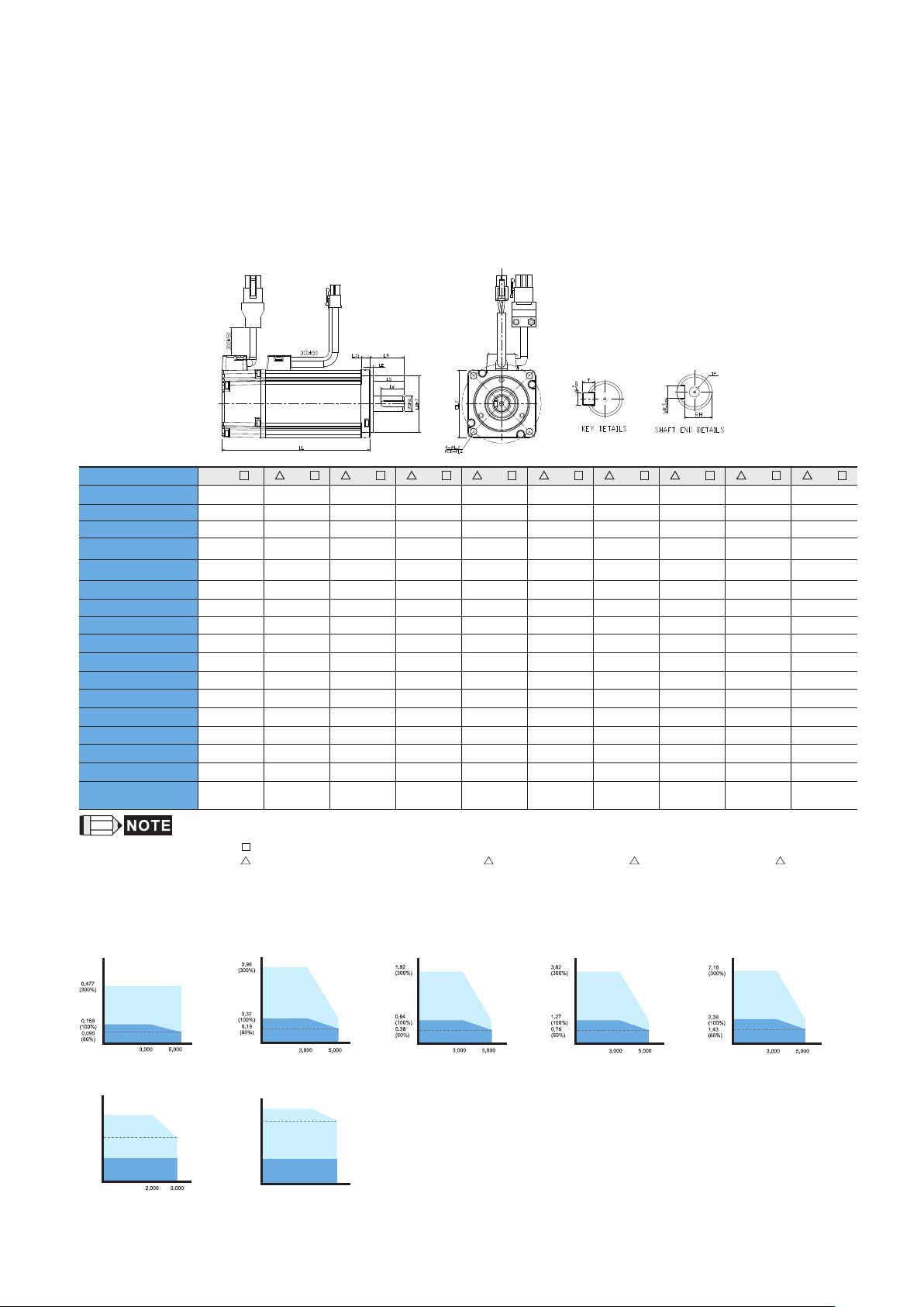
Servo Motor Dimensions
220V Series
Frame Size 86mm and below
Model
C1040F
LC
LZ
LA
S
LB
(without brake) 79.1 100.6 105.5 130.7 145.8 112.3 138.3 154.8 130.2 153.2
LL
(with brake) -- 136.8 141.6 166.8 176.37 152.8 178 187.8 161.3 184.3
LL
8 (
30 (
LS
LR
LE
LG
LW
RH
WK
W
T
TP
S C
0401 S C 0602 S C 0604 S C 0604 H C 0804 7 C 0807 S C 0807 H C 0907 S C 0910 S
40 40 60 60 60 80 80 80 86 86
4.5 4.5 5.5 5.5 5.5 6.6 6.6 6.6 6.6 6.6
46 46 70 70 70 90 90 90 100 100
+0
- 0.009
+0
- 0.021
) 8 (
) 30 (
+0
- 0.009
+0
- 0.021
) 14 (
) 50 (
+0
- 0.011
+0
- 0.025
) 14 (
) 50 (
+0
- 0.011
+0
- 0.025
) 14 (
) 50 (
+0
- 0.011
+0
- 0.025
) 14 (
) 70 (
+0
- 0.011
+0
- 0.030
) 19 (
) 70 (
+0
- 0.013
+0
- 0.030
) 19 (
) 70 (
+0
- 0.013
+0
- 0.030
) 16 (
) 80 (
+0
- 0.011
+0
- 0.030
) 16 (
) 80 (
20 20 27 27 27 27 32 32 30 30
25 25 30 30 30 30 35 35 35 35
2.5 2.5 3 3 3 3 3 3 3 3
5 5 7.5 7.5 7.5 8 8 8 8 8
16 16 20 20 20 20 25 25 20 20
6.2 6.2 11 11 11 11 15.5 15.5 13 13
3 3 5 5 5 5 6 6 5 5
3 3 5 5 5 5 6 6 5 5
3 3 5 5 5 5 6 6 5 5
M3
Depth 8M3Depth 8M4Depth 15M4Depth 15M4Depth 15M4Depth 15M6Depth 20M6Depth 20M5Depth 15M5Depth 15
1) Dimensions are in millimeters.
2) Dimensions of the servo motors may be revised without prior notice.
3) The boxes (
4) The boxes (
) in the model names are for optional configurations(keyway, brake and oil seal).
) in the model names are for encoder resolution types. ( =1: Incremental encoder, 20-bit; =2: Incremental encoder, 17-bit; =A: Absolute type)
Units: mm
+0
- 0.011
+0
- 0.030
)
)
Speed-Torque Curves (T-N Curves)
Speed (r/min)
Torque (N-m)
Continuous Duty Zone Continuous Duty Zone
▲ 0602 □S ECMA-C ▲ 0807 □ S
ECMA-C
Torque (N-m)
Intermittent Duty Zone Intermittent Duty Zone Intermittent Duty Zone Intermittent Duty Zone Intermittent Duty Zone
Torque (N-m)
7.14
(298%)
6.00
(251%)
2.38
(100%)
Continuous Duty Zone
Continuous Duty Zone
ECMA-C1040F □ S
Intermittent Duty Zone
ECMA-C ▲ 0907 □ S
Speed (r/min) Speed (r/min) Speed (r/min) Speed (r/min) Speed (r/min)
Speed (r/min)
Torque (N-m)
Torque (N-m)
8.78
(276%)
5.85
(184%)
3.18
(100%)
Continuous Duty Zone
ECMA-C
▲ 0401 □S
Intermittent Duty Zone
Continuous Duty Zone
2,000 3,000
▲ 0910 □ S
ECMA-C
21
Torque (N-m) Torque (N-m)
▲ 0604 □ S
ECMA-C
ECMA-C ▲ 0604 □ H
ECMA-C ▲ 0804 □ 7
Continuous Duty Zone
ECMA-C ▲ 0807 □ H
Page 23

220V Series
Frame Size 100mm and 130mm
LG
LR
LE
LS
LW
LC
Sh6
LBh7
LL
4-ØZ
PCD- A
0
-0.03 6
W
KEY DE TAILS
0
-0.03 6
SHAF T END DETAI LS
T
TP
RH
Model C 1010 S C 1020 S C 1330 4 E 1305 S E 1310 S E 1315 S E 1320 S
LC 100 100 130 130 130 130 130
LZ 9 9 9 9 9 9 9
LA 11 5 115 145 145 145 145 145
S 22 (
LB 95 (
(without brake)
LL
(with brake)
LL
+0
- 0.013
+0
- 0.035
) 22 (
) 95 (
+0
- 0.013
+0
- 0.035
) 24 (
) 110 (
153.3 199 187.5 147.5 147.5 167.5 187.5
192.5 226 216 183.5 183.5 202 216
+0
- 0.013
+0
- 0.035
) 22 (
) 110 (
+0
- 0.013
+0
- 0.035
) 22 (
) 110 (
+0
- 0.013
+0
- 0.035
) 22 (
) 110 (
+0
- 0.013
+0
- 0.035
) 22 (
) 110 (
LS 37 37 47 47 47 47 47
LR 45 45 55 55 55 55 55
LE 5 5 6 6 6 6 6
LG 12 12 11.5 11.5 11.5 11.5 11.5
LW 32 32 36 36 36 36 36
RH 18 18 20 18 18 18 18
WK 8 8 8 8 8 8 8
W 8 8 8 8 8 8 8
T 7 7 7 7 7 7 7
TP
M6
Depth 20
1) Dimensions are in millimeters.
2) Dimensions of the servo motors may be revised without prior notice.
3) The boxes (
4) The boxes (
) in the model names are for optional configurations(keyway, brake and oil seal).
) in the model names are for encoder resolution types. ( =1: Incremental encoder, 20-bit; =2: Incremental encoder, 17-bit; =A: Absolute type)
M6
Depth 20
M6
Depth 20
M6
Depth 20
M6
Depth 20
M6
Depth 20
Units: mm
+0
- 0.013
+0
- 0.035
M6
Depth 20
)
)
Speed-Torque Curves (T-N Curves)
Torque (N-m)
Intermittent Duty Zone
Continuous Duty Zone
Torque (N-m)
Intermittent Duty Zone
Continuous Duty Zone Continuous Duty Zone
ECMA-E
▲ 1315 □ S
Speed (r/min)
Speed (r/min)
Intermittent Duty Zone
Continuous Duty Zone
Torque (N-m)
Intermittent Duty Zone
ECMA-C
ECMA-E
▲ 1020 □ SECMA-C ▲ 1010 □ S
▲ 1320 □ S
Speed (r/min)
Speed (r/min)
Torque (N-m)
Intermittent Duty Zone Intermittent Duty Zone
Continuous Duty Zone Continuous Duty Zone
ECMA-C
▲ 1330 □ 4
Torque (N-m)
Speed (r/min)
22
ECMA-E
▲ 1305 □ S
Speed (r/min)
Torque (N-m)Torque (N-m)
Intermittent Duty Zone
Continuous Duty Zone
ECMA-E
Speed (r/min)
▲ 1310 □ S
Page 24

Servo Motor Dimensions
220V Series
Frame Size 100mm and 130mm
LG
LR
LE
LS
LW
LC
Sh6
LBh7
LL
PCD- A
4-ØZ
0
-0.03 6
W
KEY DETA ILS
0
-0.03 6
SHAF T END DETAI LS
T
TP
RH
Model F 1305 S F 1308 S F 1313 S F 1318 S G 1303 S G 1306 S G 1309 S
LC 130 130 130 130 130 130 130
LZ 9 9 9 9 9 9 9
LA 145 145 145 145 145 145 145
S 22 (
LB 110 (
(without brake)
LL
(with brake)
LL
+0
) 22 (
- 0.013
+0
) 110 (
- 0.035
139.5 147.5 187.5 202 147.5 147.5 163.5
168 183.5 216 230.7 183.5 183.5 198
+0
- 0.013
+0
- 0.035
) 22 (
) 110 (
+0
- 0.013
+0
- 0.035
) 22 (
) 110 (
+0
- 0.013
+0
- 0.035
) 22 (
) 110 (
+0
- 0.013
+0
- 0.035
) 22 (
) 110 (
+0
- 0.013
+0
- 0.035
) 22 (
) 110 (
LS 47 47 47 47 47 47 47
LR 55 55 55 55 55 55 55
LE 6 6 6 6 6 6 6
LG 11.5 11.5 11.5 11.5 11.5 11.5 11.5
LW 36 36 36 36 36 36 36
RH 18 18 18 18 18 18 18
WK 8 8 8 8 8 8 8
W 8 8 8 8 8 8 8
T 7 7 7 7 7 7 7
TP
M6
Depth 20
1) Dimensions are in millimeters.
2) Dimensions of the servo motors may be revised without prior notice.
3) The boxes (
4) The boxes (
) in the model names are for optional configurations (keyway, brake and oil seal).
) in the model names are for encoder resolution types. ( =1: Incremental encoder, 20-bit; =2: Incremental encoder, 17-bit; =A: Absolute type)
M6
Depth 20
M6
Depth 20
M6
Depth 20
M6
Depth 20
M6
Depth 20
Units: mm
+0
- 0.013
+0
- 0.035
M6
Depth 20
)
)
Speed-Torque Curves (T-N Curves)
Torque (N-m) Torque (N-m) Torque (N-m)Torque (N-m)Torque (N-m)
8.92
(280%)
5.1
(160%)
3.18
(100%)
1.59
(50%)
Intermittent Duty Zone
Continuous Duty Zone
1,500
Intermittent Duty Zone
Continuous Duty Zone
ECMA-G
▲ 1306 □ S ECMA-G ▲ 1309 □ S
Speed (r/min) Speed (r/min) Speed (r/min) Speed (r/min)
3,0002,300
Speed (r/min)
Intermittent Duty Zone
Continuous Duty Zone
ECMA-F
Torque (N-m)Torque (N-m)
Intermittent Duty Zone
Continuous Duty Zone
▲ 1308 □ S
Speed (r/min)
Intermittent Duty Zone
Continuous Duty Zone
23
Intermittent Duty Zone
Continuous Duty Zone
ECMA-F ▲ 1318 □ S ECMA-G ▲ 1303 □ SECMA-F ▲ 1313 □ SECMA-F ▲ 1305 □ S
Intermittent Duty Zone
Continuous Duty Zone
Speed (r/min)
Page 25

220V Series
Frame Size 180mm
LG
LR
LE
LS
LW
4-ØLZ
PCD -L A
LC
Sh6
Lbh7
LL
W
KEY DETA ILS
SHAF T END DETAI LS
T
TP
RH
Model E 1820 S E 1830 S E 1835 S F 1845 S F 1855 3 F 1875 3
LC 180 180 180 180 180 180
LZ 13.5 13.5 13.5 13.5 13.5 13.5
LA 200 200 200 200 200 200
S 35 (
LB 114.3 (
(without brake)
LL
(with brake)
LL
+0
) 35 (
- 0.016
+0
) 114.3 (
- 0.035
169 202.1 202.1 235.3 279.7 342.0
203.1 235.3 235.3 279.3 311.7 376.1
+0
) 35 (
- 0.016
+0
) 114.3 (
- 0.035
+0
) 35 (
- 0.016
+0
) 114.3 (
- 0.035
+0
) 42 (
- 0.016
+0
) 114.3 (
- 0.035
+0
) 42 (
- 0.016
+0
) 114.3 (
- 0.035
LS 73 73 73 73 108.5 108.5
LR 79 79 79 79 113 113
LE 4 4 4 4 4 4
LG 20 20 20 20 20 20
LW 63 63 63 63 90 90
RH 30 30 30 30 37 37
WK 10 10 10 10 12 12
W 10 10 10 10 12 12
T 8 8 8 8 8 8
TP
M12
Depth 25
1) Dimensions are in millimeters.
2) Dimensions of the servo motors may be revised without prior notice.
3) The boxes (
4) The boxes (
) in the model names are for optional configurations(keyway, brake and oil seal).
) in the model names are for encoder resolution types. ( =1: Incremental encoder, 20-bit; =2: Incremental encoder, 17-bit; =A: Absolute type)
M12
Depth 25
M12
Depth 25
M12
Depth 25
M16
Depth 32
Units: mm
+0
- 0.016
+0
- 0.035
M12
Depth 32
)
)
Speed-Torque Curves (T-N Curves)
orque (N-m) orque (N-m) orque (N-m) orque (N-m) orque (N-m)
28.65
(300%)
Intermittent Duty Zone
9.55
(100%)
6.40
(67%)
Continuous Duty Zone
ECMA-E ▲ 1820 □ S ECMA-E ▲1830 □ S ECMA-F ▲ 1830 □ S ECMA-F ▲ 1845 □ SECMA-E ▲ 1835 □ S
orque (N-m)
87.53
(300%)
Intermittent Duty Zone
35.01
(100%)
17.51
(50%)
Continuous Duty Zone
▲ 1855 □ 3
ECMA-F
Speed (r/min) Speed (r/min) Speed (r/min) Speed (r/min) Speed (r/min)
3,0002,000
Speed (r/min)
3,0001,500
42.97
(300%)
14.32
(100%)
9.59
(67%)
orque (N-m)
119.36
(250%)
47.74
(100%)
23.87
(50%)
Intermittent Duty Zone
Continuous Duty Zone
Intermittent Duty Zone
Continuous Duty Zone
ECMA-F
▲ 1875 □ 3
3,000 3,0002,000
3,0001,500
Speed (r/min)
57.29
(300%)
19.10
(100%)
9.55
(50%)
Intermittent Duty Zone
Continuous Duty Zone
1,500
24
50.13
(300%)
16.71
(100%)
11.20
(67%)
Intermittent Duty Zone
Continuous Duty Zone
71.62
(300%)
28.65
(100%)
14.33
3,0002,000
(50%)
Intermittent Duty Zone
Continuous Duty Zone
3,0001,500
Page 26

Servo Motor Dimensions
220V / 400V Series
Frame Size 220mm and above
A
Model F1221B 3 F1221F S L1221B 3 L1221F S
LC 220 220 220 220
LZ 13.5 13.5 13.5 13.5
LA 235 235 235 235
S 42 (
LB 200 (
(without brake)
LL
(with brake)
LL
LS 108 108 110 110
LR 116 11 6 116 11 6
LE 4 4 4 4
LG 20 20 20 20
LW 90 90 90 90
RH 37 49 37 49
WK 12 16 12 16
W 12 16 12 16
T 8 10 8 10
TP
1) Dimensions are in millimeters.
2) Dimensions of the servo motors may be revised without prior notice.
3) The boxes (
+0
) 55 (
- 0.016
+0
) 200 (
- 0.046
+0.03
- 0.011
+0
- 0.046
371.4 453.4 371.4 450.4
434.4 513.4 434.4 513.4
M16
Depth 32
) in the model names are for optional configurations (keyway, brake and oil seal).
M20
Depth 40
) 42 (
) 200 (
+0
- 0.016
+0
- 0.046
M16
Depth 32
) 55 (
) 200 (
Depth 40
M20
+0.03
- 0.011
+0
- 0.046
Units: mm
)
)
Speed-Torque Curves (T-N Curves)
175
(250%)
Intermittent Duty Zone
70
(100%)
52.5
Continuous Duty Zone
(75%)
1,500
ECMA-F1221B □ 3 ECMA-F1221F□ S
2,000
Torque (N-m)Torque (N-m)
Speed (r/min) Speed (r/min)
224
(240%)
Intermittent Duty Zone
95.4
(100%)
71.6
(75%)
Continuous Duty Zone
1,500
2,000
175
(250%)
Intermittent Duty Zone
70
(100%)
52.5
Continuous Duty Zone
(75%)
1,500
ECMA-L1221B □ 3 ECMA-L1221F □ S
Speed (r/min) Speed (r/min)
2,000
25
Torque (N-m)Torque (N-m)
224
(240%)
95.4
(100%)
71.6
(75%)
Intermittent Duty Zone
Continuous Duty Zone
1,500
2,000
Page 27

400V Series
Frame Size 80mm and below
Model J 0604 S J 0807 S J 0907 S J 0910 S
LC 60 80 86 86
LZ 5.5 6.6 6.6 6.6
LA 70 90 100 100
S 14(
LB 50(
(without brake)
LL
(with brake)
LL
(without oil seal)
LS
(with oil seal)
LS
LR 30 35 35 35
LE 3 3 3 3
LG 7.5 8 8 8
LW 20 25 20 20
RH 11 15.5 13 13
WK 5 6 5 5
W 5 6 5 5
T 5 6 5 5
TP
1) Dimensions are in millimeters.
2) Dimensions of the servo motors may be revised without prior notice.
3) The boxes (
4) The boxes (
+0
) 19(
- 0.011
+0
) 70(
- 0.025
+0
) 16(
- 0.013
+0
) 80(
- 0.030
+0
) 16(
- 0.011
+0
) 80(
- 0.030
130.7 138.3 130.2 153.2
166.8 178 161.3 184.3
27 32 30 30
-- 29.5 30 30
M4
Depth 15
) in the model names are for optional configurations (keyway, brake and oil seal).
) in the model names are for encoder resolution types ( =1: Incremental encoder, 20-bit; =2: Incremental encoder, 17-bit); =A: Absolute type
M6
Depth 20
M5
Depth 15
+0
- 0.011
+0
- 0.030
M5
Depth 15
Units: mm
)
)
Speed-Torque Curves (T-N Curves)
Torque (N-m) Torque (N-m) Torque (N-m) Torque (N-m)
3.82
(300%)
1.27
(100%)
0.762
(60%)
Intermittent Duty Zone
Continuous Duty Zone
3,000
ECMA-J ▲ 0604 □ S
7.16
(300%)
Intermittent Duty Zone
2.39
(100%)
1.43
(60%)
Speed (r/min) Speed (r/min) Speed (r/min) Speed (r/min)
5,000
Continuous Duty Zone
ECMA-J
▲ 0807 □ S
5,0003,000
7.14
(298%)
2.38
(100%)
Intermittent Duty Zone
Continuous Duty Zone
ECMA-J
▲ 0907 □ S
(251%)
26
8.78
(276%)
6.00
3.18
(100%)
Intermittent Duty Zone
Continuous Duty Zone
2,0002,000 3,0003,000
▲ 0910 □ S
ECMA-J
5.85
(184%)
Page 28

Servo Motor Dimensions
400V Series
Frame Size 100mm and 130mm
0
-0.03 6
W
KEY DETA ILS
0
-0.03 6
SHAF T END DETAI LS
S L
T
RH
1305
TP
S L
Model
LC
LG
LR
LE
LS
LW
LC
Sh6
LBh7
J 1010
LL
1020
S J
S J
1330
4 K
1305
4-ØLZ
PCD- LA
SK
1310
SK
1315
1320
SK
100 100 130 130 130 130 130 130 130 130
LZ 9 9 9 9 9 9 9 9 9 9
LA 115 115 145 145 145 145 145 145 145 145
S
LB
(without brake)
LL
(with brake)
LL
+0
22 (
- 0.013
+0
95 (
- 0.035
153.3 199 187.5 139.5 147.5 167.5 187.5 147.5 163.5 194.5
192.5 226 216.0 168 183.5 202 216 168.0 181 223
) 22 (
) 95 (
+0
- 0.013
+0
- 0.035
) 24 (
) 110 (
+0
- 0.013
+0
- 0.035
) 22 (
) 110 (
+0
- 0.013
+0
- 0.035
) 22 (
) 110 (
+0
- 0.013
+0
- 0.035
) 22 (
) 110 (
+0
- 0.013
+0
- 0.035
) 22 (
) 110 (
+0
- 0.013
+0
- 0.035
) 22 (
) 110 (
+0
- 0.013
+0
- 0.035
) 22 (
) 110 (
LS 37 37 47 47 47 47 47 47 47 47
LR 45 45 55 55 55 55 55 55 55 55
LE 5 5 6 6 6 6 6 6 6 6
LG 12 12 11.5 11.5 11.5 11.5 11.5 11.5 11.5 11.5
LW 32 32 36 36 36 36 36 36 36 36
RH 18 18 20 18 18 18 18 18 18 18
WK 8 8 8 8 8 8 8 8 8 8
W 8 8 8 8 8 8 8 8 8 8
T 7 7 7 7 7 7 7 7 7 7
TP
MP6
Depth 20
1) Dimensions are in millimeters.
2) Dimensions of the servo motors may be revised without prior notice.
3) The boxes (
4) The boxes (
MP6
Depth 20
MP6
Depth 20
MP6
Depth 20
MP6
Depth 20
MP6
Depth 20
MP6
Depth 20M8Depth 25
Depth 20
) in the model names are for optional configurations (keyway, brake and oil seal).
) in the model names are for encoder resolution types ( =1: Incremental encoder, 20-bit; =2: Incremental encoder, 17-bit); =A: Absolute type
1308
+0
- 0.013
+0
- 0.035
MP6
S L
) 22 (
) 110 (
Units: mm
1313
+0
- 0.013
+0
- 0.035
MP6
Depth 20
S
)
)
Speed-Torque Curves (T-N Curves)
9.54
(300%)
3.18
(100%)
1.91
(60%)
21.5
(300%)
7.16
(100%)
4.8
(67%)
Intermittent Duty Zone
Continuous Duty Zone
ECMA-J ▲ 1010 □ S
Intermittent Duty Zone
Continuous Duty Zone
ECMA-K ▲ 1315 □ S
Torque (N-m)Torque (N-m)
19.11
(300%)
Intermittent Duty Zone
6.37
(100%)
3.82
(60%)
28.65
28.65
(300%)
(300%)
9.55
9.55
(100%)
(100%)
(67%)
(67%)
Torque (N-m)Torque (N-m)
6.4
6.4
Continuous Duty Zone
ECMA-J ▲ 1020 □ S
加速領
Intermittent Duty Zone
Continuous Duty Zone
ECMA-K ▲ 1320 □ S
5,0003,000
3,0002,000
3,0002,000
Speed (r/min) Speed (r/min) Speed (r/min) Speed (r/min)
5,0003,000
Speed (r/min)
3,0002,000
Torque (N-m)
28.65
(300%)
Intermittent Duty Zone
9.55
(100%)
6.4
Continuous Duty Zone
(67%)
ECMA-J ▲ 1330 □ 4
Torque (N-m)
8.92
(284%)
Intermittent Duty Zone
3.18
(100%)
Continuous Duty Zone
1.59
(50%)
Speed (r/min) Speed (r/min) Speed (r/min)
ECMA-L
4500
3000
(110%)
1,500 1,500 1,5002,300 2,200 2,2003,000 3,000 3,000
▲ 1305 □ S
27
Torque (N-m)
7.16
(300%)
Intermittent Duty Zone
2.39
(100%)
Continuous Duty Zone
1.6
(67%)
ECMA-K ▲ 1305 □ S
Torque (N-m)
13.80
(255%)
5.39
Intermittent Duty Zone
(100%)
3.5
Continuous Duty Zone
2.70
(50%)
▲ 1308 □ S
ECMA-L
(83%)
Torque (N-m)
14.32
(300%)
Intermittent Duty Zone
4.77
(100%)
3.2
(67%)
Continuous Duty Zone
ECMA-K ▲ 1310 □ S
Torque (N-m)
23.3
(280%)
Intermittent Duty Zone
8.34
4.5
(100%)
4.17
(50%)
Continuous Duty Zone
ECMA-L
▲ 1313 □ S
Speed (r/min)
3,0003,000 2,0002,000
6
(72%)
Speed (r/min)
Page 29

400V Series
Frame Size 180mm and above
W
KEY DETA ILS
SHAF T END DETAI LS
T
RH
Model K 1820
LG
LE
LL
S L 1830
LR
LS
LW
Sh6
4-ØLZ
PCD -L A
LC
Lbh7
S L 1845
S L 1855
3 L 1875
LC 180 180 180 180 180 130
LZ 13.5 13.5 13.5 13.5 13.5 9
LA 200 200 200 200 200 145
S
LB
(without brake)
LL
(with brake)
LL
+0
35 (
114.3(
) 35 (
- 0.016
+0
) 114.3(
- 0.035
169 202.1 235.3 279.7 342.0 163.5
203.1 235.3 279.3 311.7 376.1 198
+0
) 35 (
- 0.016
+0
) 114.3(
- 0.035
+0
) 42 (
- 0.016
+0
) 114.3(
- 0.035
+0
) 42 (
- 0.016
+0
) 114.3(
- 0.035
+0
- 0.016
+0
- 0.035
LS 73 73 73 108.5 108.5 47
LR 79 79 79 11 3 11 3 55
LE 4 4 4 4 4 6
LG 20 20 20 20 20 11.5
LW 63 63 63 90 90 36
RH 30 30 30 37 37 18
WK 10 10 10 12 12 8
W 10 10 10 12 12 8
T 8 8 8 8 8 7
TP
M12
Depth 25
1) Dimensions are in millimeters.
2) Dimensions of the servo motors may be revised without prior notice.
3) The boxes (
4) The boxes (
) in the model names are for optional configurations (keyway, brake and oil seal).
) in the model names are for encoder resolution types ( =1: Incremental encoder, 20-bit; =2: Incremental encoder, 17-bit); =A: Absolute type
M12
Depth 25
M12
Depth 25
M16
Depth 32
M16
Depth 32
TP
Units: mm
S M 1309 □ S
) 22 (
) 110(
+0
- 0.013
+0
- 0.035
M6
Depth 20
)
)
Speed-Torque Curves (T-N Curves)
Torque (N-m) Torque (N-m) Torque (N-m)
28.66
(300%)
9.55
(100%)
6.4
(67%)
Torque (N-m)
21.48
(250%)
8.59
(100%)
4.3
(50%)
Intermittent Duty Zone
Continuous Duty Zone
Continuous Duty Zone
2,000 3,000
Intermittent Duty Zone
Continuous Duty Zone
1,000
ECMA-M ▲ 1309 □ S
57.29
(300%)
Intermittent Duty Zone
19.10
(100%)
9.55
(50%)
Speed (r/min) Speed (r/min) Speed (r/min) Speed (r/min) Speed (r/min)
Speed (r/min)
2,000
Continuous Duty Zone
3,0001,500
ECMA-L ▲ 1830 □ SECMA-K ▲ 1820 □ S
71.62
(300%)
28.65
(100%)
14.33
(50%)
Intermittent Duty Zone
Continuous Duty Zone
ECMA-L ▲ 1845 □ S
28
87.53
(300%)
Intermittent Duty Zone
35.01
(100%)
17.51
(50%)
3,0001,500
Continuous Duty Zone Continuous Duty Zone
ECMA-L ▲ 1855 □ 3
Torque (N-m)Torque (N-m)
119.36
(250%)
Intermittent Duty Zone
47.74
(100%)
23.87
3,0001,500
(50%)
ECMA-L ▲ 1875 □ S
3,0001,500
Page 30

Part Names and Functions
●
LED Display / Operation Panel / Charge LED
• LED Display
The 5 digit, 7 segment LED displays the
servo status or fault codes.
• Operation Panel
Function keys used to perform status
display, monitor and diagnostic,
function and parameter setting.
Function Keys:
MODE : Press this key to select/change mode
SHIFT : Press this key to shift cursor to the left
UP : Press this key to increase values on the display
DOWN : Press this key to decrease values on the display
SET : Press this key to store data
• Charge LED
A lit LED indicates that either power is connected to
the servo drive or a residual charge is present in the
drive's internal power components.
●
Full-Closed Loop Control Interface
• Used to connect linear scale and encoder for
controlling A, B, Z phase signals.
●
I/O Interface
• Used to connect Delta's DVP series
PLC or other external controllers for
controlling I/O signals.
●
High-speed Communication Port
• 1-in/1-out communication ports offer easy serial
connection.
●
Motor Encoder Interface
• Used to connect the encoder of the servo motor
●
Extension Digital Input
Connection Port
• Used to connect a removable digital
input terminal block. Max. 6 digital inputs
can be added.
●
Serial Communication Port
• Used to connect PLC, HMI, and other
controllers for RS-485 / RS-232 serial
communication.
●
USB Connection Port
• Used to connect personal computers or
notebooks.
• Ver 1.1 USB is equipped as standard.
• Direct connectivity to personal computers
or notebooks, capable of accessing data
through ASDA-Soft configuration software.
• Monitor speed upon software is up to 1Mbps.
Operation
Panel
Charge LED
LED
Display
29
Page 31

●
Internal & External Regenerative Resistor Terminal /
Control Circuit Terminal / Main Circuit Terminal
• Internal & External Regenerative Resistor Terminal
1. When using an external resistor, connect it to P ⊕ and C , and ensure an open circuit
between P ⊕ and D.
2. When using an internal resistor, ensure the circuit is closed between P ⊕ and D, and
the circuit is open between P ⊕ and C. (Note: Please refer to the table of regenerative
resistor specifications for the models with a built-in regenerative resistor.)
3. When using an external braking unit, connect it to P ⊕ and, and ensure an open circuit
between P ⊕ and D, and P ⊕ and C.
• When using an external braking unit, connect it to P ⊕ and
• Control Circuit Terminal (L1C, L2C or DC24V, DC0V)
- 220V Series: L1C, L2C are used to connect 200 ~ 230Vac,
50/60Hz single-phase or three-phase power supply.
- 400V Series: DC24V, DC0V are used to connect 24Vdc ±10%
power supply.
• Main Circuit Terminal (R, S, T)
- 220V Series: Used to connect 200~230Vac, 50/60Hz commercial
power supply.
- 400V Series: Used to connect 380~480Vac, 50/60Hz commercial
power supply.
●
Servo Motor Output (U, V, W)
• Used to connect servo motor. Never
connect the output terminal to main
circuit power as the AC drive may be
damaged beyond repair if incorrect cables
are connected to the output terminals.
●
Ground Terminal
• Used to connect grounding wire of power
supply and servo motor.
●
Heatsink
• Used to secure servo drive and for heat
dissipation.
*Note: The figures are for illustration purposes only. Actual models may differ slightly
in appearance to illustrations provided.
30
Page 32

Wiring
200V Series
Position (PT) Control Mode (for Pulse Command Input)
Pul se inpu t (Open -coll ector N PN),
for t he use of i ntern al powe r suppl y
Cont rolle r
SG
Pul se inpu t (Open -coll ector P NP),
for t he use of i ntern al powe r suppl y
Cont rolle r
SG
Pul se inpu t (Open -coll ector N PN),
for t he use of e xtern al powe r suppl y
Cont rolle r
SG
Pul se inpu t (Open -coll ector P NP),
for t he use of e xtern al powe r suppl y
Cont rolle r
SG
Pul se inpu t (Line d river ).
It re quire s 5V powe r suppl y only.
Nev er appl y a 24V pow er supp ly.
Cont rolle r
SG
Hig h-spe ed puls e input ( Line dr iver) .
It re quire s 5V powe r suppl y only.
Nev er appl y a 24V pow er supp ly.
Cont rolle r
Pull- hi_S
1KΩ
1KΩ
Pull- hi_S
+
DC 24V
-
/PULS E
+
DC24V
-
1KΩ
1KΩ
SIGN
/SIGN
PULSE
/PULS E
HSIGN
/HSIG N
HPULS E
/HPUL SE
SG
GND GND
VDD
/SIGN
/PULSE
COM-
/PULS E
/SIGN
PULSE
/PULS E
VDD
COM-
PULSE
35
SIGN
/SIGN
SIGN
/SIGN
46
40
38
29
13
17
37
41
45
17
43
41
36
37
45
35
37
41
43
41
36
37
36
37
43
41
100Ω
Serv o Drive
DC24V
Max.
Max.
Input p ulse
Input p ulse
Appro x.
frequ ency is
frequ ency is
1KΩ
200Kp ps
200Kp ps
51Ω
51Ω
Appro x.1KΩ
51Ω
51Ω
Max.
Input p ulse
frequ ency is
200Kp ps
Serv o Drive
DC24V
51Ω
51Ω
51Ω
51Ω
Serv o Drive
Appro x.
1KΩ
51Ω
51Ω
Appro x.1KΩ
51Ω
51Ω
Serv o Drive
51Ω
51Ω
51Ω
51Ω
Max. Input pulse
frequ ency is 200Kpps
Serv o Drive
51Ω
51Ω
51Ω
51Ω
Serv o Drive
2KΩ
100Ω
2KΩ
2KΩ
2KΩ
Max.
Max.
Input p ulse
Input p ulse
frequ ency is
frequ ency is
200Kp ps
200Kp ps
Max.
Input p ulse
frequ ency is
200Kp ps
Max.
Input pulse
frequency is
200Kpps
Max. Input pulse
frequency is
200Kpps
Max. Input pulse
frequency is
200Kpps
Max. Input pulse
frequency is
500Kpps
Max. Input pulse
frequency is
500Kpps
Servo Drive
ASDA-A 2 Se ri es
AC 200/ 23 0V
Singl e- phase o r
Three -p hase
*3
50/60 H z
MCCB
MC
R
S
T
-
L1C
L2C
CN1
/SI GN
Pulse I np ut
(Line D ri ver)
10K Ω±10 V
High- sp eed
Pulse I np ut
(Line D ri ver)
Twis ted-p air or
twi sted- shiel d
cab le
10KΩ
10KΩ
V
V
SG
SON
CCLR
TCM0
TCM1
ARST
NL
PL
EMGS
SRD Y
1.5 KΩ
ZSP D
1.5 KΩ
24V
HOM E
1.5 KΩ
TPO S
1.5 KΩ
1.5 KΩ
ALR M
A Phas e Pulse
B Pha se Puls e
Enc oder
Pul se Outp ut
Please note:
*1. 400W ~ 4.5kW servo drives provide a built-in regenerative resistor.
*2. The brake oil has no polarity.
*3. Single-phase connections are for servo drives 1.5kW and below only.
Z Pha se Puls e
Z Pha se Open
Col lecto r
SIG N
/PU LSE
PUL SE
T-RE F
GND
/HS IGN
HSI GN
/HP ULSE
HPU LSE
MON 1
GND
MON 2
VDD
COM +
COM -
DI1
DI2
DI3
DI4
DI5
DI6
DI7
DI8
DO1 +
DO1 -
DO2 +
DO2 -
DO3 +
DO3 -
DO4 +
DO4 -
DO5 +
DO5 -
OA
/OA
OB
/OB
OZ
/OZ
OCZ
GND
37
36
41
43
18
13
40
46
29
38
16
12, 1 3, 19
15
17
11
45, 47,49
9
10
34
8
33
32
31
30
7
6
5
4
3
2
1
26
28
27
21
22
25
23
50
24
48
13
10KΩ
DC24V
4.7KΩ
4.7KΩ
4.7KΩ
4.7KΩ
4.7KΩ
4.7KΩ
4.7KΩ
4.7KΩ
Max. O utput
Curr ent 50mA
Volta ge 30V
1
0KΩ
4.7KΩ
4.7KΩ
4.7KΩ
4.7KΩ
4.7KΩ
4.7KΩ
CN2
5
4
7
9
14, 16
13, 15
CN3
6
5
4
3
2
1
CN7
1
2
3
4
5
6
7
CN4
1
2
3
4
CN5
CN6
P
D
C
U
V
W
8
4
5
3
2
9
1
6
7
1,9
2,1 0
3,11
4,1 2
5,1 3
6,1 4
7,1 5
8,1 6
+
+5V
Opt A
Opt / A
Opt B
Opt / B
Opt Z
Opt / Z
GND
GND
*1
Red
White
Black
Green
T+
Blu e
T -
Blu e/Bla ck
-
-
-
-
+5V
Red /Red & Wh it
GND
Bla ck/Bl ack & Whi t
RS4 85-
RS4 85+
RS2 32_RX
-
RS2 32_TX
GND
COM +
EDI 9-
EDI 10-
EDI 11 -
EDI 12-
EDI 13-
EDI 14-
+5V D C
Dat a-
Dat a+
Gro und
CANop en
CAN H
CAN L
CAN G ND
-
-
-
CAN G ND
-
Reg enera tive
Res istor
24V
Pow er
Sup ply
(
BRKR
EMGS
*2
Bra ke
Enc oder
Twis ted-p air or
twi sted- shiel d
cab le
SG
31
Page 33

200V Series
Serv o Dr ive
r
Position (PR) Control Mode (for Internal Procedure Control)
AC 200/23 0V
Single- ph as e or
Three-p ha se
50/60 Hz
Twiste d-p air or
twi sted-sh iel d
cab le
Encod er
Pulse O utp ut
*3
±10 V
10KΩ
10KΩ
CTRG
EMGS
24V
A Phase Pu lse
B Phase P uls e
Z Pha se Pulse
Z Pha se Open
Colle cto r
10K
SON
POS0
POS1
ARST
NL
PL
SRD Y
ZSP D
HOM E
TPO S
ALR M
MCCB
Ω
V
V
1.5 KΩ
1.5 KΩ
1.5 KΩ
1.5 KΩ
1.5 KΩ
MC
R
ASDA -A2 Serie s
S
T
-
L1 C
L2 C
10K
Ω
4.7KΩ
4.7KΩ
4.7KΩ
4.7KΩ
4.7KΩ
4.7KΩ
4.7KΩ
4.7KΩ
Max. O utput
Curr ent 3A
Volta ge 50V
10KΩ
CN2
DC24V
CN3
CN7
4.7KΩ
4.7KΩ
4.7KΩ
4.7KΩ
4.7KΩ
4.7KΩ
CN4
CN5
CN6
CN1
18
T-REF
13
GND
16
MON 1
GND
12, 13, 1 9
MON 2
VDD
COM +
COM -
DI1
DI2
DI3
DI4
DI5
DI6
DI7
DI8
DO1 +
DO1 -
DO2 +
DO2 -
DO3 +
DO3 -
DO4 +
DO4 -
DO5 +
DO5 -
OA
/OA
OB
/OB
OZ
/OZ
OCZ
GND
15
17
11
45,47 ,49
9
10
34
8
33
32
31
30
7
6
5
4
3
2
1
26
28
27
21
22
25
23
50
24
48
13
SG
P
D
C
U
V
W
5
4
7
9
14,16
13,15
6
5
4
3
2
1
1
2
3
4
5
6
7
1
2
3
4
8
4
5
3
2
9
1
6
7
1,9
2,1 0
3,11
4,1 2
5,1 3
6,1 4
7,1 5
8,1 6
+
*1
Red
White
Black
Green
T+
Blue
T -
Blu e/Black
-
-
-
-
Red/R ed & Wh it
+5V
Bla ck/Bl ack & Whi t
GND
RS4 85-
RS4 85+
RS2 32_RX
-
RS232 _TX
GND
COM +
EDI9-
EDI10 -
EDI11-
EDI 12 -
EDI13 -
EDI14 -
+5V DC
Data-
Data+
Gro und
+5V
Opt A
Opt / A
Opt B
Opt / B
Opt Z
Opt / Z
GND
GND
CANop en
CAN H
CAN L
CAN G ND
-
-
-
CAN G ND
-
Regen era ti ve
Resis tor
24V
EMGS
Power
BRKR
*2
Suppl y
Brake
Encod er
Twiste d-p air o
twi sted- shield
cable
(
SG
Please note:
*1. 400W ~ 4.5kW servo drives provide a built-in regenerative resistor.
*2. The brake oil has no polarity.
*3. Single-phase connections are for servo drives 1.5kW and below only.
32
Page 34

Wiring
Serv o Dr ive
r
200V Series
Speed (S), Torque (T) Control Mode (for Analog Voltage Input and Internal Parameter
Setting)
AC 200/23 0V
Single- ph as e or
Three-p ha se
50/60 Hz
Twiste d-p ai r or
twi sted- sh iel d
cable
TRQLM / S PD LM
SPD0 / TC M0
SPD1 / TC M1
Encod er
Pulse O utp ut
10KΩ
10KΩ
ARST
CCWL
EMGS
24V
A Phase Pu lse
B Pha se Pulse
Z Pha se Pulse
Z Pha se Open
Colle cto r
SON
CWL
SRD Y
ZSP D
TSP D
BRK R
ALR M
MCCB
10KΩ±10 V
10KΩ±10 V
V
V
1.5 KΩ
1.5 KΩ
1.5 KΩ
1.5 KΩ
1.5 KΩ
MC
V-REF
GND
T-REF
GND
MON 1
GND
MON 2
SG
VDD
COM +
COM -
DI1
DI2
DI3
DI4
DI5
DI6
DI7
DI8
DO1 +
DO1 -
DO2 +
DO2 -
DO3 +
DO3 -
DO4 +
DO4 -
DO5 +
DO5 -
OA
/OA
OB
/OB
OZ
/OZ
OCZ
GND
R
ASDA -A2 Serie s
S
T
-
L1 C
L2 C
CN1
42
44
18
13
16
12, 13, 1 9
15
17
11
45,47 ,49
9
10
34
8
33
32
31
30
7
6
5
4
3
2
1
26
28
27
21
22
25
23
50
24
48
13
4.7KΩ
4.7KΩ
4.7KΩ
4.7KΩ
4.7KΩ
4.7KΩ
4.7KΩ
4.7KΩ
Max. O utput
Curr ent 50mA
Volta ge 30V
10KΩ
10KΩ
DC24V
**31
+
P
D
C
Red
U
White
V
Black
W
CN2
5
4
7
9
14,16
13,15
Green
T+
T -
-
-
+5V
GND
10KΩ
10KΩ
Regen era ti ve
Resis tor
24V
Blu e
Blu e/Black
-
-
Red/R ed & Wh it
Black /Bl ack & Whi t
EMGS
Power
Suppl y
(
BRKR
*2
Bra ke
Encod er
Twiste d-p ai r o
twi sted-sh iel d
cable
SG
CN3
6
RS4 85-
5
RS485 +
4
RS2 32_RX
3
-
2
1
RS2 32_TX
GND
CN7
4.7KΩ
4.7KΩ
4.7KΩ
4.7KΩ
4.7KΩ
4.7KΩ
EDI9-
2
EDI10 -
3
EDI11-
4
EDI 12 -
5
EDI 13 -
6
EDI14 -
7
COM +
1
CN4
1
+5V DC
2
Data-
3
Data+
4
Gro und
CN5
+5V
8
Opt A
4
Opt / A
5
Opt B
3
Opt / B
2
Opt Z
9
Opt / Z
1
GND
6
GND
7
CN6
CANop en
1,9
CAN H
2,1 0
CAN L
3,11
CAN GND
4,1 2
-
5,1 3
-
6,1 4
-
7,1 5
CAN G ND
8,1 6
-
Please note:
*1. 400W ~ 4.5kW servo drives provide a built-in regenerative resistor.
*2. The brake oil has no polarity.
*3. Single-phase connections are for servo drives 1.5kW and below only.
33
Page 35

200V Series
Servo Drive
CANopen Communication Mode
AC 200/ 230V
Three -phas e
50/60 H z
24V
Enc oder
uls e Outpu t
*3
Res erved
Res erved
Res erved
ORG P
NL
PL
EMG S
SRDY
1.5 KΩ
ZSPD
1.5 KΩ
HOME
1.5 KΩ
TPOS
1.5 KΩ
1.5 KΩ
ALRM
A Phas e Pulse
B Pha se Puls e
Z Pha se Puls e
Z Pha se Open
Col lecto r
MCCB
MC
VDD
COM +
COM -
DI1
DI2
DI3
DI4
DI5
DI6
DI7
DI8
DO1 +
DO1 -
DO2 +
DO2 -
DO3 +
DO3 -
DO4 +
DO4 -
DO5 +
DO5 -
OA
/OA
OB
/OB
OZ
/OZ
OCZ
GND
RS4 85-
RS4 85+
RS2 32_RX
-
RS2 32_TX
GND
R
S
T
L1C
L2C
DC24V
CN1
17
11
45, 47,49
4.7KΩ
9
4.7KΩ
10
4.7KΩ
34
4.7KΩ
8
4.7KΩ
33
4.7KΩ
32
4.7KΩ
31
4.7KΩ
30
7
6
5
4
3
2
1
26
28
27
21
22
25
23
50
24
48
13
Max. O utput
Curr ent 50mA
Volta ge 30V
CN3
6
5
4
3
2
1
ASDA-A2 serie s
CN2
5
4
7
9
14, 16
13, 15
CN4
CN5
CN6
P
D
C
U
V
W
1
2
3
4
8
4
5
3
2
9
1
6
7
1
2
3
4
5
6
7
8
9
10
11
12
13
14
15
16
+
Red
White
Black
Green
T+
T -
-
-
+5V
GND
+5V D C
Dat a-
Dat a+
GND
+5V
Opt A
Opt / A
Opt B
Opt / B
Opt Z
Opt / Z
GND
GND
CAN open
CAN H
CAN L
CAN G ND
-
-
-
CAN G ND
-
CAN H
CAN L
CAN G ND
-
-
-
CAN G ND
-
*1
ege nerat ive
R
Res istor
Blu e
Blu e/Bla ck
-
-
Red /Red & Wh it
Bla ck/Bl ack & Whi t
(Ap plicabl e to ASD A-A2- M)
24V
BRK R
EMG S
SG
Dat a Input
Dat a Outpu t
Pow er
Sup ply
Bra ke
*2
Enc oder
Twis ted-p air or
twi sted- shiel d
cab le
DMC NET
CN6
1
2
3
4
5
6
7
8
9
10
11
12
13
14
15
16
DMC NET_1 A
DMC NET_1 B
DMC NET_2 A
-
-
DMC NET_2 B
-
-
DMC NET_1 A
DMC NET_1 B
DMC NET_2 A
-
-
DMC NET_2 B
-
-
(Ap plicabl e to ASD A-A2- F)
Dat a Input
Dat a Outpu t
Please note:
*1. 400W ~ 4.5kW servo drives provide a built-in regenerative resistor.
*2. The brake oil has no polarity.
*3. Single-phase connections are for servo drives 1.5kW and below only.
34
Page 36

Wiring
400V Series
Position (PT) Control Mode (for Pulse Command Input)
Pul se inpu t (Open -coll ector N PN),
for t he use of i ntern al powe r suppl y
Cont rolle r
SG
Pul se inpu t (Open -coll ector P NP),
for t he use of i ntern al powe r suppl y
Cont rolle r
SG
Pul se inpu t (Open -coll ector N PN),
for t he use of e xtern al powe r suppl y
Cont rolle r
SG
Pul se inpu t (Open -coll ector P NP),
for t he use of e xtern al powe r suppl y
Cont rolle r
SG
Pul se inpu t (Line d river ).
It re quire s 5V powe r suppl y only.
Nev er appl y a 24V pow er supp ly.
Cont rolle r
SG
Hig h-spe ed puls e input ( Line dr iver) .
It re quire s 5V powe r suppl y only.
Nev er appl y a 24V pow er supp ly.
Cont rolle r
Pull- hi_S
1KΩ
1KΩ
Pull- hi_S
+
DC 24V
-
/PULS E
+
-
1KΩ
1KΩ
PULSE
/PULS E
HSIGN
/HSIG N
HPULS E
/HPUL SE
SG
GND GND
DC24V
/SIGN
/SIGN
/SIGN
SIGN
VDD
/PULSE
COM-
/PULS E
PULSE
VDD
COM-
PULSE
/PULS E
17
35
37
41
45
SIGN
/SIGN
35
37
41
SIGN
/SIGN
36
37
43
41
46
40
38
29
13
Serv o Drive
DC24V
Max.
Input p ulse
Appro x.
frequ ency is
1KΩ
200Kp ps
51Ω
51Ω
Appro x.1KC
51Ω
51Ω
Max. In put
pulse f requ
ency is
200Kp ps
Serv o Drive
DC24V
17
51Ω
43
51Ω
41
51Ω
36
51Ω
37
45
Serv o Drive
Appro x.
1KΩ
51Ω
51Ω
Appro x.1KΩ
51Ω
51Ω
Max. Input pulse
frequ ency is 200Kpps
Serv o Drive
51Ω
43
51Ω
41
51Ω
36
51Ω
37
Max. Input pulse
frequ ency is 200Kpps
Serv o Drive
51Ω
51Ω
51Ω
51Ω
Max. Input pulse frequ
ency is 500Kpps
Serv o Drive
2KΩ
100Ω
2KΩ
2KΩ
100Ω
2KΩ
Max.
Input p ulse
frequ ency is
200Kp ps
Max. In put
pulse f requ
ency is
200Kp ps
Max.
Input pulse
frequency is
200Kpps
Max. Input pulse
frequency is
200Kpps
Max. Input pulse
frequency is
500Kpps
Servo Drive
ASDA-A 2 Se ri es
CN1
10K
Ω
10K
DC2 4V
Ω
4.7K
Ω
4.7K
Ω
4.7K
Ω
4.7K
Ω
4.7K
Ω
4.7K
Ω
4.7K
Ω
4.7K
Max. O utput
Curr ent 50mA
Volta ge 30V
Ω
AC 380/ 48 0V
Three -p hase
High- sp eed
Pulse I np ut
(Line D ri ver)
Twis ted-p air or
twi sted- shiel d
cab le
Enc oder
Pul se Outp ut
Pulse I np ut
(Line D ri ver)
Ω
10K
Ω
10K
SON
CCLR
TCM0
TCM1
ARST
CWL
CCWL
EMGS
SRD Y
ZSP D
24V
HOM E
TPO S
ALR M
A Phas e Pulse
B Pha se Puls e
Z Pha se Puls e
Z Pha se Open
Col lecto r
MCCB
10K
V
V
DC 24V
Power
Suppl y
Ω±10V
SG
Ω
1.5 K
Ω
1.5 K
Ω
1.5 K
Ω
1.5 K
Ω
1.5 K
MC
/SI GN
SIG N
/PU LSE
PUL SE
T-RE F
GND
/HS IGN
HSI GN
/HP ULSE
HPU LSE
MON 1
GND
MON 2
VDD
COM +
COM -
DI1
DI2
DI3
DI4
DI5
DI6
DI7
DI8
DO1 +
DO1 -
DO2 +
DO2 -
DO3 +
DO3 -
DO4 +
DO4 -
DO5 +
DO5 -
OA
/OA
OB
/OB
OZ
/OZ
OCZ
GND
R
S
T
-
24V
0V
37
36
41
43
18
13
40
46
29
38
16
12, 13,19
15
17
11
45, 47,49
9
10
34
8
33
32
31
30
7
6
5
4
3
2
1
26
28
27
21
22
25
23
50
24
48
13
Please note:
*1 Servo drives under 1.5kW provide a built-in regenerative resistor.
*2 The brake oil has no polarity.
5
4
Res erved
Res erved
14, 16
13, 15
Ω
4.7K
Ω
4.7K
Ω
4.7K
Ω
4.7K
Ω
4.7K
Ω
4.7K
CN2
CN3
CN7
CN4
CN5
CN6
D
C
U
V
W
6
5
4
3
2
1
1
2
3
4
5
6
7
1
2
3
4
8
4
5
3
2
9
1
6
7
1,9
2,1 0
3,11
4,1 2
5,1 3
6,1 4
7,1 5
8,1 6
+
P
*1
Red
White
Black
Green
Blu e
T+
T -
Blu e/Bla ck
-
-
-
-
+5V
Red /Red & Wh ite
GND
Bla ck/Bl ack & Whi te
RS4 85-
RS4 85+
RS2 32_RX
-
RS2 32_TX
GND
COM +
EDI 9-
EDI 10-
EDI 11 -
EDI 12-
EDI 13-
EDI 14-
+5V D C
Dat a-
Dat a+
Gro und
+5V
Opt A
Opt / A
Opt B
Opt / B
Opt Z
Opt / Z
GND
GND
CANop en
CAN H
CAN L
CAN G ND
-
-
-
CAN G ND
-
Reg enera tive
Res istor
24V
Pow er
Sup ply
(
BRKR
EMGS
*2
Bra ke
Enc oder
Twis ted-p air or
twi sted- shiel d
cab le
SG
35
Page 37

400V Series
Servo Dr iv e
r
Position (PR) Control Mode (for Internal Procedure Control)
AC 380/48 0V
Three-p ha se
Pulse Inp ut
(Line Dri ve r)
Enc oder
Pul se Outp ut
10K
24V
MCCB
Ω±10V
10K
V
Ω
Ω
10K
V
SON
CTRG
POS0
POS1
ARST
NL
PL
EMGS
SRD Y
1.5 K
ZSP D
1.5 K
HOM E
1.5 K
TPO S
1.5 K
1.5 K
ALR M
A Phas e Pulse
B Pha se Puls e
Z Pha se Puls e
Z Pha se Open
Col lecto r
DC 24V
Power
Supply
SG
Ω
Ω
Ω
Ω
Ω
MC
T-RE F
GND
MON 1
GND
MON 2
VDD
COM +
COM -
DI1
DI2
DI3
DI4
DI5
DI6
DI7
DI8
DO1 +
DO1 -
DO2 +
DO2 -
DO3 +
DO3 -
DO4 +
DO4 -
DO5 +
DO5 -
OA
/OA
OB
/OB
OZ
/OZ
OCZ
GND
R
ASDA -A2 Series
S
T
-
24V
0V
CN1
18
13
16
12, 13,19
15
17
11
45, 47,49
9
10
34
8
33
32
31
30
7
6
5
4
3
2
1
26
28
27
21
22
25
23
50
24
48
13
10K
4.7K
4.7K
4.7K
4.7K
4.7K
4.7K
4.7K
4.7K
Max. O utput
Curr ent 3A
Volta ge 50V
Ω
DC2 4V
Ω
Ω
Ω
Ω
Ω
Ω
Ω
Ω
*1
+
P
D
C
U
V
W
Ω
10K
5
4
Res erved
Res erved
14, 16
13, 15
Green
CN2
T+
T -
-
+5V
GND
Reg enera tive
Res istor
Red
White
Black
Blu e
Blu e/Bla ck
-
-
Red /Red & Wh ite
Bla ck/Bl ack & Whi te
24V
EMGS
Pow er
Sup ply
(
BRKR
*2
Bra ke
Enc oder
Twis ted-p air o
twi sted- shiel d
cab le
SG
CN3
6
RS4 85-
5
RS4 85+
4
RS2 32_RX
3
-
2
1
RS2 32_TX
GND
CN7
1
2
3
4
5
6
7
CN4
1
2
3
4
CN5
8
4
5
3
2
9
1
6
7
CN6
1,9
2,1 0
3,11
4,1 2
5,1 3
6,1 4
7,1 5
8,1 6
COM +
EDI 9-
EDI 10-
EDI 11-
EDI 12-
EDI 13-
EDI 14-
+5V D C
Dat a-
Dat a+
Gro und
+5V
Opt A
Opt / A
Opt B
Opt / B
Opt Z
Opt / Z
GND
GND
CANopen
CAN H
CAN L
CAN G ND
-
-
-
CAN G ND
-
Ω
4.7K
Ω
4.7K
Ω
4.7K
Ω
4.7K
Ω
4.7K
Ω
4.7K
Please note:
*1 Servo drives under 1.5kW provide a built-in regenerative resistor.
*2 The brake oil has no polarity.
36
Page 38

Wiring
Serv o Dr ive
r
400V Series
Speed (S), Torque (T) Control Mode (for Analog Voltage Input and Internal Parameter
Setting)
AC 380/48 0V
Three-p ha se
MCCB
DC 24V
Power
Supply
MC
R
ASDA -A2 Serie s
S
T
-
24V
0V
CN1
42
44
18
13
16
12, 13,19
15
17
VDD
11
COM +
45, 47,49
COM -
9
DI1
10
DI2
34
DI3
8
DI4
33
DI5
32
DI6
31
DI7
30
DI8
DO1 +
DO1 -
DO2 +
DO2 -
DO3 +
DO3 -
DO4 +
DO4 -
DO5 +
DO5 -
OA
/OA
OB
/OB
OZ
/OZ
48
13
10K
10K
Ω
4.7K
Ω
4.7K
Ω
4.7K
Ω
4.7K
Ω
4.7K
Ω
4.7K
Ω
4.7K
Ω
4.7K
7
6
5
4
3
2
1
26
28
27
21
22
25
23
50
24
Max. O utput
Curr ent 50mA
Volta ge 30V
Pulse Inp ut
(Line Dri ve r)
Enc oder
Pul se Outp ut
10K
±10 V
10K
±10 V
Ω
10K
Ω
10K
SON
TRQLM/SPDLM
SPD0/TCM0
SPD1/TCM1
ARST
CWL
CCWL
EMGS
SRD Y
ZSP D
TSP D
24V
BRK R
ALR M
A Phas e Pulse
B Pha se Puls e
Z Pha se Pulse
Z Pha se Open
Col lector
Ω
Ω
V
V
1.5 K
1.5 K
1.5 KΩ
1.5 K
1.5 K
V-RE F
GND
T-RE F
GND
MON 1
GND
MON 2
SG
Ω
Ω
Ω
Ω
OCZ
GND
Please note:
*1 Servo drives under 1.5kW provide a built-in regenerative resistor.
*2 The brake oil has no polarity.
Ω
Ω
DC2 4V
*1
+
P
D
C
Red
U
White
V
Black
W
Ω
10K
Ω
10K
5
4
Res erved
Res erved
14, 16
13, 15
Green
CN2
T+
T -
-
+5V
GND
Reg enerati ve
Res istor
24V
Blu e
Blu e/Bla ck
-
-
Red /Red & Wh ite
Bla ck/Bl ack & White
EMGS
Pow er
Sup ply
(
BRKR
*2
Bra ke
Enc oder
Twis ted-p air o
twi sted- shield
cab le
SG
CN3
6
RS4 85-
5
RS4 85+
4
RS2 32_RX
3
2
1
-
RS2 32_TX
GND
CN7
1
CN4
1
2
3
4
COM +
2
EDI 9-
3
EDI 10-
4
EDI 11-
5
EDI 12-
6
EDI 13-
7
EDI 14-
+5V D C
Dat a-
Dat a+
Gro und
Ω
4.7K
Ω
4.7K
Ω
4.7K
Ω
4.7K
Ω
4.7K
Ω
4.7K
CN5
+5V
8
Opt A
4
Opt / A
5
Opt B
3
Opt / B
2
Opt Z
9
Opt / Z
1
GND
6
GND
7
CN6
CANopen
CAN H
1,9
CAN L
2,1 0
CAN G ND
3,11
-
4,1 2
-
5,1 3
-
6,1 4
CAN G ND
7,1 5
-
8,1 6
37
Page 39

400V Series
Servo Drive
MCCB
CANopen Communication Mode (for ASDA-A2-M Series)
MC
P
D
C
U
V
W
CN2
14, 16
13, 15
CN4
CN5
CN6
10
11
12
13
14
15
16
+
5
4
7
9
1
2
3
4
8
4
5
3
2
9
1
6
7
1
2
3
4
5
6
7
8
9
*1
Red
White
Black
Green
T+
T -
-
+5V
GND
+5V D C
Dat a-
Dat a+
GND
+5V
Opt A
Opt / A
Opt B
Opt / B
Opt Z
Opt / Z
GND
GND
CAN open
CAN H
CAN L
CAN G ND
-
-
-
CAN G ND
-
CAN H
CAN L
CAN G ND
-
-
-
CAN G ND
-
Reg enera tive
Res istor
24V
Blu e
Blu e/Bla ck
-
-
Red /Red & Wh ite
Bla ck/Bl ack & Whi te
(Ap plica ble to ASD A-A2- M)
Dat a Input
Dat a Outpu t
24V
Enc oder
Pul se Outp ut
AC 380/ 480 V
Three -ph as e
Res erved
Res erved
Res erved
Res erved
ORG P
EMG S
SRDY
ZSPD
HOME
TPOS
ALRM
A Phas e Pulse
B Pha se Puls e
Z Pha se Puls e
Z Pha se Open
Col lecto r
R
ASDA-A2 series
S
T
VDD
COM +
COM DI1
DI2
DI3
DI4
DI5
DI6
DI7
DI8
DO1 +
DO1 DO2 +
DO2 DO3 +
DO3 DO4 +
DO4 DO5 +
DO5 -
OA
/OA
OB
/OB
OZ
/OZ
OCZ
GND
-
24V
0V
CN1
17
11
45, 47,49
9
10
34
8
33
32
31
30
7
6
5
4
3
2
1
26
28
27
21
22
25
23
50
24
48
13
Max. O utput
Curr ent 50mA
Volta ge 30V
DC2 4V
Ω
4.7K
Ω
4.7K
Ω
4.7K
Ω
4.7K
Ω
4.7K
Ω
4.7K
Ω
4.7K
Ω
4.7K
DC 24V
Power
Suppl y
NL
PL
Ω
1.5 K
Ω
1.5 K
Ω
1.5 K
Ω
1.5 K
Ω
1.5 K
CN3
RS4 85RS4 85+
RS2 32_RX
RS2 32_TX
GND
6
5
4
3
2
1
Pow er
Sup ply
BRKR
EMGS
Bra ke
*2
Enc oder
Twis ted-p air or
twi sted- shiel d
cab le
SG
DMC NET
CN6
1
2
3
4
5
6
7
8
9
10
11
12
13
14
15
16
DMC NET_1 A
DMC NET_1 B
DMC NET_2 A
-
-
DMC NET_2 B
-
-
DMC NET_1 A
DMC NET_1 B
DMC NET_2 A
-
-
DMC NET_2 B
-
-
(Ap plica ble to ASDA- A2- F)
Dat a Input
Dat a Outpu t
Please note:
*1 Servo drives under 1.5kW provide a built-in regenerative resistor.
*2 The brake oil has no polarity.
38
Page 40

ASDA-Soft Configuration Software
• Strong CAPTURE and COMPARE functions for position
latch and detection help you complete system configuration
quickly.
• User-friendly E-CAM editing interface is provided for
designing E-CAM outlines and curves freely. In addition,
quick settings for flying shear and rotary cut applications
are offered.
39
Page 41

• Versatile on-line monitoring function, similar to a
digital oscilloscope is able to quickly record the
status and data of each axis. Real-time monitoring
is easy.
• Convenient alarm display function is capable of
troubleshooting the system easily and recommending
timely corrective actions.
• Easy-to-use editing interface is designed for new and
enhanced PR control mode. Homing, point-to-point
and other motion control functions for multi-axis
positioning control are easily achieved.
40
Page 42

Optional Accessories
●
Quick Connectors
• Used for 100W to 300W servo drives.
• One operating lever is
provided for wire to
terminal block insertion.
●
Power Cables
• 3m and 5m standard cables are
available.
• Customized service is offered to
meet the needs of customers.
• Two types are selectable: with brake
and without brake.
●
Encoder Cables
• 3m and 5m standard cables are
available.
• Customized service is offered to
meet the needs of customers.
●
RS-232 Communication Cables
• Connects ASDA-A2 to PLC, HMI
and other controllers via RS-232
communication.
• Standard cable length is 3m
41
Page 43

●
CN1 I/O connector
• Delta Part Number: ASD-IF-SC5020
●
Terminal Block Modules
• Easy installation and wiring.
• 0.5m connection cable is
provided. Easy to reduce the
space required.
• Easy to expand system's I/O
configuration.
●
Regenerative Resistors
• For selecting a regenerative
resistor, please refer to e
table of regenerative resistor
specifications on page 74.
●
USB Communication
Cables (for PC)
• USB Communication
Cables (for PC)
• USB1.1 is equipped as
standard.
●
CANopen Accessories
• Delta's TAP-CN03 distribution
box connects ASDA-A2 to
Delta's PLC CAN Master
• CANopen communication
cable is provided
●
RS-485 Connectors
• Used to connect multiple
ASDA-A2 series products
by RS-485 interface through
Modbus serial communication.
Note: The figures are for illustration purposes only. Actual models may differ slightly
in appearance to illustrations provided.
42
Page 44

Servo Drive Specifications
220V Series
ASDA-A2 Series
Phase / Voltage
Permissible Voltage Range
Input Current(3PH)
Power
supply
Input Current(1PH)
Continuous Output Current
Cooling System
Encoder Resolution / Feedback Resolution
Control of Main Circuit
Tuning Modes
Regenerative Resistor
Max. Input Pulse Frequency
(Only for Non-DMCNET mode)
Pulse Type
Command Source
Smoothing Strategy
Electronic Gear
Torque Limit Operation
Position Control Mode
Feed Forward Compensation
Analog Input
Command
(Only for Non-DMCNET
mode)
Speed Control Range
Command Source
Smoothing Strategy
Torque Limit Operation
Frequency Response Characteristic
Speed Control Mode
Speed Accuracy
(At rated rotation speed)
Analog Input
Command
(Only for Non-DMCNET
mode)
Command Source
Mode
Smoothing Strategy
Torque Control
Speed Limit Operation
Analog Monitor Output
Inputs
Outputs
Digital Inputs / Outputs
Protective Functions
Communication Interface
Installation Site
Altitude
Atmospheric Pressure
Operating Temperature
Storage Temperature
Humidity
Vibration
Environment
IP Rating
Power System
Approvals
Footnote:
*1. Rated rotation speed: When full load, speed ratio is defined as the minimum speed (the motor will not pause).
*2. When command is rated rotation speed, the speed fluctuation rate is defined as: (Empty load rotation speed Full load rotation speed) / Rated rotation speed
*3. TN system: A power distribution system having one point directly earthed, the exposed conductive parts of the installation being connected to that points by protective earth conductor.
(Units: Arms)
(Units: Arms)
(Units: Arms)
(Only for Non-DMCNET mode)
Voltage Range
Input Resistance
Time Constant
*1
*2
Voltage Range
Input Resistance
Time Constant
100 W 200 W 400 W 750 W 1 kW 1.5 kW 2 kW 3 kW 4.5 kW 5.5 kW 7.5 kW 11 kW 15kW
01 02 04 07 10 15 20 30 45 55 75 1B 1F
Three-phase / Single-phase 220V
1-phase / 3-phase 200 ~ 230VAC, -15% ~ 10% 3-phase 200 ~ 230VAC, -15% ~ 10%
0.8 1.11 1.86 3.66 4.68 6.33 8.76 9.83 17.5 19.4 26.3 48 63
1 1.92 3.22 6.78 8.88 10.96 - - - - - - -
0.9 1.55 2.6 5.1 7.3 8.86 13.4 19.4 32.5 40 47.5 54.4 70
Natural Air Circulation Fan Cooling
None Built-in External
Max. 500Kpps / 4Mpps (Line driver), Max. 200Kpps (Open collector)
External pulse train (PT mode)
Electronic gear N/M multiple N: 1~32767, M: 1:32767 (1/50<N/M<25600)
1: 5000 1: 3000 1: 2000
Servo on, Reset, Gain switching, Pulse clear, Zero speed CLAMP, Command input reverse control, Command triggered, Speed/
Torque limit enabled, Position command selection, Motor stop, Speed position selection, Position / Speed mode switching, Speed /
Torque mode switching, Torque / Position mode switching, PT / PR command switching, Emergency stop, Forward / Reverse inhibit
limit, Reference "Home" sensor, Forward / Reverse operation torque limit, Move to "Home", Electronic Cam (E-CAM), Forward /
Reverse JOG input, Event trigger PR command, Electronic gear ratio (Numerator) selection and Pulse inhibit input
* Please note that the above digital signals and inputs are available only for Non-DMCNET mode. In DMCNET mode, it is recommended to write digital inputs into the servo
drives through DMCNET communication, and the digital inputs should be used for Emergency Stop, Forward / Reverse Inhibit limit and Reference "Home" sensor only.
Servo ready, Servo on, At Zero speed, At Speed reached, At Positioning completed, At Torques limit, Servo alarm (Servo fault)
activated, Electromagnetic brake control, Homing completed, Output overload warning, Servo warning activated, Position command
overflow, Forward / Reverse software limit, Internal position command completed, Capture operation completed output., Motion
Overcurrent, Overvoltage, Undervoltage, Motor overheated, Regeneration error, Overload, Overspeed, Abnormal pulse control
command, Excessive deviation, Encoder error, Adjustment error, Emergency stop activated, Reverse/ Forward limit switch error,
Position excessive deviation of full-close control loop, Serial communication error, Input power phase loss, Serial communication
Indoor location (free from direct sunlight), no corrosive liquid and gas (far away from oil mist, flammable gas, dust)
External analog signal
External analog signal
Monitor signal can set by parameters (Output voltage range: ±8V)
Encoder signal output (A, B, Z Line Driver and Z Open Collector )
control completed output., Master position of E-CAM (Electronic CAM)
time out, short circuit protection of U, V, W, and CN1, CN2, CN3 terminals
0ºC ~ 55ºC (If operating temperature is above 45ºC, forced cooling will be required)
9.80665 m/s2 (1G) less than 20Hz, 5.88 m/s2 (0.6G) 20 to 50Hz
IEC/EN 61800-5-1, UL 508C, C-tick
AC
Incremental encoder: 20-bit ;Absolute encoder: 17-bit
SVPWM(Space Vector Pulse Width Modulation) Control
Pulse + Direction, A phase + B phase, CCW pulse + CW pulse
Set by parametersor via analog input
0.01% or less at 0 to 100% load fluctuation
0.01% or less at ±10% power fluctuation
0.01% or less at 0ºC to 50ºC ambient temperature fluctuation
Set by parametersor via analog input
RS-232 / RS-485 / CANopen / USB / DMCNET
Altitude 2000m or lower above sea level
Auto / Manual
(Only for Non-DMCNET mode)
Low-pass and P-curve filter
Set by parameters
Set by parameters
0 ~ ±10 V
10K
354.6 μs
(Only for Non-DMCNET mode)
Low-pass and S-curve filter
Maximum 1kHz
0 ~ ±10 V
10K
2.2 μs
(Only for Non-DMCNET mode)
Low-pass filter
86kPa ~ 106kPa
-20ºC ~ 65ºC
0 ~ 90% RH (non-condensing)
IP20
TN System
/ Internal parameters (PR mode)
DC
Ω
(Only for Non-DMCNET mode)
DC
Ω
(Only for Non-DMCNET mode)
*3
3-phase 220V
/ Internal parameters
/ Internal parameters
AC
43
Page 45

400V Series
ASDA-A2 Series
Input Voltage
Input Current
Power
Control
Input Power
Permissible Voltage Range
Input Current
Main
Power
Continuous Output Current
Cooling System
Encoder Resolution / Feedback Resolution
Control of Main Circuit
Tuning Modes
Regenerative Resistor
Max. Input Pulse Frequency
DMCNET mode)
Pulse Type
Command Source
Smoothing Strategy
Electronic Gear
Torque Limit Operation
Position Control Mode
Feed Forward Compensation
Analog Input
Command
(Only for Non-DMCNET
mode)
Speed Control Range
Command Source
Smoothing Strategy
Torque Limit Operation
Frequency Response Characteristic
Speed Control Mode
Speed Accuracy
Analog Input
Command
(Only for Non-DMCNET
mode)
Command Source
Mode
Smoothing Strategy
Torque Control
Speed Limit Operation
Analog Monitor Output
Inputs
Digital
Inputs / Outputs
Outputs
Protective Functions
Communication Interface
Installation Site
Altitude
Atmospheric Pressure
Operating Temperature
Storage Temperature
Humidity
Vibration
Environment
IP Rating
Power System
Approvals
Footnote:
*1. Rated rotation speed: When full load, speed ratio is defined as the minimum speed (the motor will not pause).
*2. When command is rated rotation speed, the speed fluctuation rate is defined as: (Empty load rotation speed Full load rotation speed) / Rated rotation speed
*3. TN system: A power distribution system having one point directly earthed, the exposed conductive parts of the installation being connected to that points by protective earth conductor.
(Units: Arms)
(Only for Non-DMCNET mode)
(Units: Arms)
(Only for Non-
Voltage Range
Input Resistance
Time Constant
*1
*2
Voltage Range
Input Resistance
Time Constant
750 W 1kW 1.5kW 2kW 3kW 4.5kW 5.5kW 7.5kW
07 10 15 20 30 45 55 75 1B 1F
0.89A 1.18A 1.66A
21.4W 28.2W 39.85W
2.22 3.02 4.24 5.65 8.01 11.9 14.1 17.27
3.07 3.52 5.02 6.66 11.9 20 22.37 30
Incremental encoder: 20-bit ;Absolute encoder: 17-bit
SVPWM(Space Vector Pulse Width Modulation) Control
Built-in External
Max. 500Kpps / 4Mpps (Line driver), Max. 200Kpps (Open collector)
Pulse + Direction, A phase + B phase, CCW pulse + CW pulse
External pulse train
Electronic gear N/M multiple N: 1~32767, M: 1:32767 (1/50<N/M<25600)
1: 5000 1: 3000
Servo on, Reset, Gain switching, Pulse clear, Zero speed CLAMP, Command input reverse control, Command triggered, Speed/
Torque limit enabled, Position command selection, Motor stop, Speed position selection, Position / Speed mode switching, Speed /
Torque mode switching, Torque / Position mode switching, PT / PR command switching, Emergency stop, Forward / Reverse inhibit
limit, Reference "Home" sensor, Forward / Reverse operation torque limit, Move to "Home", Electronic cam, Forward / Reverse JOG
* Please note that the above digital signals and inputs are available only for Non-DMCNET mode. In DMCNET mode, it is recommended to write digital inputs into the servo
drives through DMCNET communication, and the digital inputs should be used for Emergency Stop, Forward / Reverse Inhibit limit and Reference "Home" sensor only.
Servo ready, Servo on, At Zero speed, At Speed reached, At Positioning completed, At Torques limit, Servo alarm (Servo fault)
activated, Electromagnetic brake control, Homing completed, Output overload warning, Servo warning activated, Position command
overflow, Forward / Reverse software limit, Internal position command completed, Capture operation completed output., Motion
Overcurrent, Overvoltage, Undervoltage, Motor overheated, Regeneration error, Overload, Overspeed, Abnormal pulse control
command, Excessive deviation, Encoder error, Adjustment error, Emergency stop activated, Reverse/ Forward limit switch error,
Position excessive deviation of full-close control loop, Serial communication error, Input power phase loss, Serial communication time
input, Event trigger PR command, Electronic gear ratio (Numerator) selection and Pulse inhibit input
Indoor location (free from direct sunlight), no corrosive liquid and gas (far away from oil mist, flammable gas, dust)
External analog signal
Set by parametersor via analog input
0.01% or less at 0 to 100% load fluctuation
0.01% or less at ±10% power fluctuation
0.01% or less at 0ºC to 50ºC ambient temperature fluctuation
External analog signal
Set by parametersor via analog input
Monitor signal can set by parameters (Output voltage range: ±8V)
Encoder signal output (A, B, Z Line Driver and Z Open Collector )
control completed output., Master position of E-CAM (Electronic CAM)
out, short circuit protection of U, V, W, and CN1, CN2, CN3 terminals
RS-232 / RS-485 / CANopen / USB / DMCNET
Altitude 2000m or lower above sea level
0ºC ~ 55ºC(If operating temperature is above 45ºC, forced cooling will be required)
9.80665 m/s2 (1G) less than 20Hz, 5.88 m/s2 (0.6G) 20 to 50Hz
IEC/EN 61800-5-1, UL 508C, C-tick
24VDC, ±10%
3-phase380 ~ 480VAC, ±10%
Fan Cooling
Auto / Manual
(Only for Non-DMCNET mode)
Low-pass and P-curve filter
Set by parameters
Set by parameters
0 ~ ±10 V
10K
2.2 μs
(Only for Non-DMCNET mode)
Low-pass and S-curve filter
Maximum 1kHz
0 ~ ±10 V
10K
2.2 μs
(Only for Non-DMCNET mode)
Low-pass filter
86kPa ~ 106kPa
-20ºC ~ 65ºC
0 ~ 90% RH (non-condensing)
IP20
TN System
/Internal parameters
DC
Ω
(Only for Non-DMCNET mode)
DC
Ω
(Only for Non-DMCNET mode)
*3
/ Internal parameters
/ Internal parameters
11
kW 15 kW
2A
48W
28.95 39.47
28.1 38.65
44
Page 46

Servo Drive Dimensions
220V Series
100W / 200W / 400W
Weight
1.5 (3.3)
45(1.77)
27.5(1.08)
)
2
.
0
(
2
.
5
Units: mm(inches)
70(2.76)
170(6.69)
750W / 1.0kW / 1.5kW
Weight
2.0 (4.4)
162.5(6.4)
12(0.47)
65(2.5 6)
PE TERMINA L
1
2
.
0
(
5
.
5
173(6.81)
)
7
70(2.76)
180(7 .0 9)
163(6.42)
13(0 .51)
1) Dimensions are in millimeters (inches); Weights are in kilograms (kg) and (pounds (lbs)).
2) Dimensions and weights of the servo drive may be revised without prior notice.
47(1.8 3)
173 (6.81)
Ground Terminal
45
Page 47

2.0kW / 3.0kW
Weight
2.89 (6.36)
82(3.23)
)
2
70(2.76)
.2
0
(
5
.
5
203(7.99)
4.5kW
Weight
4.4 (10.0)
203(7.99)
14.5(0.57)
62(2.44)
6
(
0
.
2
4
PE TER MINA L
110(4.33)
70(2.76)
206(8. 11 )
91(3.58)
)
215.6(8.49)
230(9.06)
91(3.58)
1) Dimensions are in millimeters (inches); Weights are in kilograms (kg) and (pounds (lbs)).
2) Dimensions and weights of the servo drive may be revised without prior notice.
245(9.65)
Ground Terminal
46
Page 48

Servo Drive Dimensions
220V Series
5.5kW
Weight
5.5 (12.1)
6
(
0
.
2
4
)
123(4.84) 70(2 .7 6)
107(4.21 )
Units: mm(inches)
206(8.1 1)
7.5kW
Weight
5.9 (13)
6(0 .24
247(9.72 )
26 0(10.24)
230(9.06 )
Ground Termina l
107(4.21)
136(5.35 )
119.5(4.70)
)
232(9.1 3)
244.75(9.65)
70(2.76 )
205.4(8.09 )
245(9.65 )
72.48(2.85)
107 (4.21)
1) Dimensions are in millimeters (inches); Weights are in kilograms (kg) and (pounds (lbs)).
2) Dimensions and weights of the servo drive may be revised without prior notice.
44.9(1.77 )
47
Page 49

11kW / 15kW
Weight
20 (44)
218 .7
225
438
458
412. 7
8
210
8
10
1) Dimensions are in millimeters (inches); Weights are in kilograms (kg) and (pounds (lbs)).
2) Dimensions and weights of the servo drive may be revised without prior notice.
225
305
Screw: M4x0.7
Screw Torque: 14 (kgf-cm)
48
Page 50

Servo Drive Dimensions
400V Series
750W / 1.0kW / 1.5kW
Weight
2.89 (6.36)
82(3.23)
5
Units: mm(inches)
)
2
2
.
0
(
5
.
70(2.76) 203(7.99 )
2.0kW / 3.0kW / 4.5kW / 5.5kW
Weight
5.5 (12.1)
203(7.99)
14(0 .55) 62(2.44)
6
(
0
.
2
4)
230( 9.06 )
123(4.84 )
107(4. 21 )
216(8.5)
70(2 .76)
205.4(8. 11 )
245( 9.65 )
Ground Termina l
107(4.21 )
1) Dimensions are in millimeters (inches); Weights are in kilograms (kg) and (pounds (lbs)).
2) Dimensions and weights of the servo drive may be revised without prior notice.
49
Page 51

7.5
kW
Weight
5.5 (12.1)
254.2 (10)
6(0 .
24
)
247(9.72)
136(5. 35 )
119.5(4. 70 )
70(2.76)
205.4(8.09 )
11kW / 15kW
Weight
10.3(22.66)
400
381
Ø8.5
250
231
107(4. 21)
44.9(1.77 )
66 212.2
1) Dimensions are in millimeters (inches); Weights are in kilograms (kg) and (pounds (lbs)).
2) Dimensions and weights of the servo drive may be revised without prior notice.
50
Page 52

Optional Cables and Connectors
●
Power Connectors
ASDBCAPW0000 (for 200V drives)
ASDBCAPW0100 (for 200V drives, with brake cable)
ASD-CAPW1000
MS 3106A-20-18S
ASD-CAPW2000
MS 3106A-24-11S
ASD-CAPW5400 (for 400V drives)
ASD-CAPW5100 (for 400V drives, with brake cable)
1010SLSL-4-4SS10SL -4S
ASD-CAPW4000
Straight Plug WPS3106A-32-17S
StraightStraight P Plulu g Wg W
ASD-CNBR1000
CLAMP:WPS3057-20ACLAMP:WPS3057-20A
CLAMP:WPS3057-20A
CLAMP: WPS3106A 10SL-4S-R
51
Page 53

●
Power Cables
ASD-ABPW0003, ASD-ABPW0005 (for 200V drives)
L
ASD-CAPW5403, ASD-CAPW5405 (for 400V drives)
L
ASD-ABPW0103, ASD-ABPW0105 (for 200V drives, with brake cable)
A
L
Item Part No.
1 ASD-ABPW0003 3000 ± 100 118 ± 4
2 ASD-ABPW0005 5000 ± 100 197 ± 4
Item Part No.
1 ASD-CAPW5403 3000 ± 100 118 ± 4
2 ASD-CAPW5405 5000 ± 100 197 ± 4
Item Part No.
1 ASD-ABPW0103 3000 ± 100 118 ± 4
2 ASD-ABPW0105 5000 ± 100 197 ± 4
L
mm inch
L
mm inch
L
mm inch
ASD-CAPW5103, ASD-CAPW5105 (for 400V drives, with brake cable)
L
ASD-CAPW1003, ASD-CAPW1005
L
Item Part No.
1 ASD-CAPW5103 3000 ± 100 118 ± 4
2 ASD-CAPW5105 5000 ± 100 197 ± 4
(50 mm)
(1.97 inch)
(80 mm)
(3.15 inch)
Item Part No. Straight
1 ASD-CAPW1003 3106A-20-18S 3000 ± 100 118 ± 4
2 ASD-CAPW1005 3106A-20-18S 5000 ± 100 197 ± 4
L
mm inch
L
mm inch
52
Page 54

Optional Cables and Connectors
(3.94 inch)
●
Power Cables
ASD-CAPW1103, ASD-CAPW1105 (with brake cable)
(50 mm)
(1.97 inch)
ASDBCAPW1203, ASDBCAPW1205
L
ASD-CAPW1303, ASD-CAPW1305 (with brake cable)
L
Item Part No. Straight
1 ASD-CAPW1103 3106A-20-18S 3000 ± 100 118 ± 4
2 ASD-CAPW1105 3106A-20-18S 5000 ± 100 197 ± 4
Item Part No. Straight
1 ASD-BCAPW1203 3106A-20-18S 3000 ± 100 118 ± 4
2 ASDB-CAPW1205 3106A-20-18S 5000 ± 100 197 ± 4
(80 mm)
(3.15 inch)
(80 mm)
(3.15 inch)
L
mm inch
(80 mm)
(3.15 inch)
(100 mm)
(3.94 inch)
L
mm inch
ASD-A2PW1003, ASD-A2PW1005
L
L
(100 mm)
Item Part No. Straight
1 ASD-CAPW1303 3106A-20-18S 3000 ± 100 118 ± 4
2 ASD-CAPW1305 3106A-20-18S 5000 ± 100 197 ± 4
(50 mm)
(1.97 inch)
(80 mm)
(3.15 inch)
Item Part No. Straight
1 ASD-A2PW1003 3106A-20-18S 3000 ± 100 118 ± 4
2 ASD-A2PW1005 3106A-20-18S 5000 ± 100 197 ± 4
L
mm inch
L
mm inch
53
Page 55

●
Power Cables
ASD-A2PW1103, ASD-A2PW1105 (with brake cable)
(50 mm)
(1.97 inch)
ASD-CAPW2003, ASD-CAPW2005
ASD-CAPW2103,
ASD-CAPW2105
L
(with brake cable)
L
Item Part No. Straight
Item Part No. Straight
(80 mm)
(3.15 inch)
L
mm inch
1 ASD-A2PW1103 3106A-20-18S 3000 ± 100 118 ± 4
2 ASD-A2PW1105 3106A-20-18S 5000 ± 100 197 ± 4
(80 mm)
(3.15 inch)
(100 mm)
(3.94 inch)
L
mm inch
1 ASD-CAPW2003 3106A-24-11S 3000 ± 100 118 ± 4
2 ASD-CAPW2005 3106A-24-11S 5000 ± 100 197 ± 4
(80 mm)
(3.15 inch)
ASD-CAPW2203, ASD-CAPW2205
L
L
(100 mm)
(3.94 inch)
Item Part No. Straight
1 ASD-CAPW2103 3106A-24-11S 3000 ± 100 118 ± 4
2 ASD-CAPW2105 3106A-24-11S 5000 ± 100 197 ± 4
(80 mm)
(3.15 inch)
(100 mm)
(3.94 inch)
Item Part No. Straight
1 ASD-CAPW2203 3106A-24-11S 3000 ± 100 118 ± 4
2 ASD-CAPW2205 3106A-24-11S 5000 ± 100 197 ± 4
L
mm inch
L
mm inch
54
Page 56

Optional Cables and Connectors
●
Power Cables
ASD-CAPW2303, ASD-CAPW2305 (with brake cable)
(80 mm)
(3.15 inch)
L
(100 mm)
(3.94 inch)
ASD-CAPW3203,ASD-CAPW3205
ASD-CAPW3303,ASD-CAPW3305
Item Part No. Straight
1 ASD-CAPW3203 3106A-24-11S 3000 ± 100 118 ± 4 3100 ± 100 122 ± 4
2 ASD-CAPW3205 3106A-24-11S 5000 ± 100 197 ± 4 5100 ± 100 201 ± 4
(with brake cable)
L
Item Part No. Straight
1 ASD-CAPW2303 3106A-24-11S 3000 ± 100 118 ± 4
2 ASD-CAPW2305 3106A-24-11S 5000 ± 100 197 ± 4
L
L1
(80 mm)
(3.15 inch)
L
mm inch
L L1
mm inch mm inch
(80 mm)
L1
(3.15 inch)
ASD-CAPW4503, ASD-CAPW4505
Item Part No. Straight
1 ASD-CAPW3303 3106A-24-11S 3000 ± 100 118 ± 4 3100 ± 100 122 ± 4
2 ASD-CAPW3305 3106A-24-11S 5000 ± 100 197 ± 4 5100 ± 100 201 ± 4
L1
Item Part No. Straight
1 ASD-CAPW4503 3106A-32-17S 3100 ± 100 122 ± 4
2 ASD-CAPW4505 3106A-32-17S 5100 ± 100 201 ± 4
L L1
mm inch mm inch
L1
mm inch
55
Page 57

●
Power Cables
ASD-CAPW4703, ASD-CAPW4705 (with brake cable)
300 REF.
ASD-CAPW4603, ASD-CAPW4605
80 mm
L1
Item Part No. Straight
1 ASD-CAPW4703
2 ASD-CAPW4705
L1
Item Part No. Straight
1 ASD-CAPW4603 3106A-32-17S 3100 ± 100 122 ± 4
2 ASD-CAPW4605 3106A-32-17S 5100 ± 100 201 ± 4
8 mm
L
mm inch
3106A-32-17S 3100 ± 100 122 ± 4
3106A-10SL-4S 3100 ± 100 122 ± 4
3106A-32-17S 5100 ± 100 201 ± 4
3106A-10SL-4S 5100 ± 100 201 ± 4
L
mm inch
ASD-CAPW4803, ASD-CAPW4805
300 REF.
(with brake cable)
80 mm
L1
Item Part No. Straight
1 ASD-CAPW4803
2 ASD-CAPW4805
8 mm
L
mm inch
3106A-32-17S 3100 ± 100 122 ± 4
3106A-10SL-4S 3100 ± 100 122 ± 4
3106A-32-17S 5100 ± 100 201 ± 4
3106A-10SL-4S 5100 ± 100 201 ± 4
56
Page 58

Optional Cables and Connectors
●
Encoder Connectors
●
Encoder Connectors
ASD-ABEN0000
●
Incremental Encoder Cables
ASD-ABEN0003,ASD-ABEN0005
L
ASD-CAEN1003,ASD-CAEN1005
L
ASD-CAEN1000
Item Part No.
1 ASD-ABEN0003 3000 ± 100 118 ± 4
2 ASD-ABEN0005 5000 ± 100 197 ± 4
Item Part No. Straight
1 ASD-CAEN1003 3106A-20-29S 3000 ± 100 118 ± 4
2 ASD-CAEN1005 3106A-20-29S 5000 ± 100 197 ± 4
L
mm inch
L
mm inch
●
Absolute Encoder Cables
ASD-A2EB0003,ASD-A2EB0005
355±10
ASD-A2EB1003,ASD-A2EB1005
±
0
3
355±10
5
±
0
3
L
5
L
Item Part No.
1 ASD-A2EB0003 3000 ± 100 118 ± 4
2 ASD-A2EB0005 5000 ± 100 197 ± 4
Item Part No.
1 ASD-A2EB1003 3000 ± 100 118 ± 4
2 ASD-A2EB1005 5000 ± 100 197 ± 4
L
mm inch
L
mm inch
57
Page 59

●
86.8mm
15 ± 5
15 ± 5
Battery Box Cord AW (Connects to the battery side of the encoder cable)
3864573700
25±5
15±5
Units: mm
See detail A
detail A
(RED)1
(BLACK)2
●
Battery Box Cord IW (Connects to CN8)
3864811900
See detail A
detail A
1 (BLACK)
2 (RED)
●
Battery Boxes with batteries
Single Battery Box
ASD-MDBT0100
Dual Battery Box
ASD-MDBT0200
Units: mm
200±10
Units: mm
200 ± 10
See detail B
detail B
1(RED)
2(BLACK)
See detail B
detail B
1 (RED)
2 (BLACK)
●
I/O Signal Connector (CN1)
ASD-CNSC0050
68
35
R3
.
25
●
Terminal Block Module
22
ASD-BM-50A
86.8 mm
50.7 mm
50.7mm
45
64. 5
146.4 mm
146.4 mm
72 .5
26
R
2
.
5
0.5m
58
Page 60

Optional Cables and Connectors
H1
H2
L ± 10
1
8
8
1
L
●
RS-232 Communication Cable
ASD-CARS0003
L
Item Part No.
1 ASD-CARS0003 3000 ± 100 118 ± 4
●
Communication Cable between Drive and Computer (for PC)
L
mm inch
DOP-CAUSBAB
A B
P4
P1
●
CANopen Communication Cable
TAP-CB03,TAP-CB05
CONDU CTO R INSU LATO R
ALUMI NUM
TIN NE D COP PE R BRA ID
PVC JAC KET
P2
P1
Item Part No.
1 DOP-CAUSBAB 1400 ± 30 55 ± 1.2
Item Part No.
1 TAP-CB03 300±10 11 ±0.4
2 TAP-CB05 500±10 19±0.4
P3
P4
L
mm inch
L
mm inch
●
CANopen Distribution Box
TAP-CN03
66.50[2.62]
Units: mm[inch]
87.00[3.43]
59
42.00[1.65]
1) Other accessories for ASDA-A2 series will be increased gradually.
2) Accessories images shown here may differ from actual product appearance.
Please refer to the actual product appearance.
Page 61

●
22.83
22.83
RS-485 Connector
Units: mm[inch]
ASD-CNIE0B06
2
4
20.35
6
●
CN1 I/O Connector
ASD-IF-SC5020
15.8
1
3
5
Units: mm[inch]
55.0
26.0
28.3
17.6
9.5
15.28
25
14.5
PIN11:PULL_HI_PS
PIN12:/PULSE
PIN13:PULSE
PIN14:/SIGN
PIN15:SIGN
PIN16:OCZ
PIN17:GND
PIN18:DO4+
52.4
PIN19:DO3+
PIN20:CN_GND
ASD-IF-SC5020
1. 2.
PIN11:PULL_HI_PS
PIN12:/PULSE
PIN13:PULSE
PIN14:/SIGN
PIN15:SIGN
PIN16:OCZ
PIN17:GND
PIN18:DO4+
PIN19:DO3+
PIN20:CN_GND
45.5
7.7
PIN10:DO2+
PIN9:DO1+
PIN8:DI7-
PIN7:DI4-
PIN6:DI3-
PIN5:DI2-
PIN4:DI1-
PIN3:COM-
PIN2:COM+
PIN1:VDD
41.3
45.5
1
2
PIN10:DO2+
PIN9:DO1+
PIN8:DI7-
PIN7:DI4-
PIN6:DI3-
PIN5:DI2-
PIN4:DI1-
PIN3:COM-
PIN2:COM+
PIN1:VDD
7.7
60
Page 62

Servo Drive, Servo Motor and Accessories
Combinations
220V Series
100W Servo Drive and 50W Low Inertia Servo Motor
Servo Drive
Low Inertia Servo Motor
Power Cable (Without Brake) ASD-ABPW000X
Power Connector (Without Brake) ASDBCAPW0000
Power Cable (With Brake) ASD-ABPW010X
Power Connectors (With Brake) ASDBCAPW0100
Incremental Encoder Cable ASD-ABEN000X
Absolute Encoder Cable ASD-A2EB000X
Encoder Connectors ASD-ABEN0000
(X=3 indicates cable length is 3m; X=5 indicates cable length is 5m)
ASD-A2-0121-
ECMA-C1040F
S
200W Servo Drive and 200W Low Inertia Servo Motor
Servo Drive
Low Inertia Servo Motor
Power Cable (Without Brake) ASD-ABPW000X
Power Connector (Without Brake) ASDBCAPW0000
Power Cable (With Brake) ASD-ABPW010X
Power Connector (With Brake) ASDBCAPW0100
Incremental Encoder Cable ASD-ABEN000X
Absolute Encoder Cable ASD-A2EB000X
Encoder Connector ASD-ABEN0000
(X=3 indicates cable length is 3m; X=5 indicates cable length is 5m)
ASD-A2-0221-
ECMA-C
0602 S
100W Servo Drive and 100W Low Inertia Servo Motor
Servo Drive
Low Inertia Servo Motor
Power Cable (Without Brake) ASD-ABPW000X
Power Connector (Without Brake) ASDBCAPW0000
Power Cable (With Brake) ASD-ABPW010X
Power Connectors (With Brake) ASDBCAPW0100
Incremental Encoder Cable ASD-ABEN000X
Absolute Encoder Cable ASD-A2EB000X
Encoder Connectors ASD-ABEN0000
(X=3 indicates cable length is 3m; X=5 indicates cable length is 5m)
ASD-A2-0121-
ECMA-C
0401 S
400W Servo Drive and 400W Low Inertia Servo Motor
Servo Drive
ASD-A2-0421-
ECMA-C
Low Inertia Servo Motor
ECMA-C 0604 H
ECMA-C 0804 7
Power Cable (Without Brake) ASD-ABPW000X
Power Connector (Without Brake) ASDBCAPW0000
Power Cable (With Brake) ASD-ABPW010X
Power Connector (With Brake) ASDBCAPW0100
Incremental Encoder Cable ASD-ABEN000X
Absolute Encoder Cable ASD-A2EB000X
Encoder Connector ASD-ABEN0000
(X=3 indicates cable length is 3m; X=5 indicates cable length is 5m)
0604 S
400W Servo Drive and 500W Medium Servo Motor
Servo Drive
Medium Servo Motor
Power Cable (Without Brake) ASD-CAPW100X
Power Cable (With Brake) ASD-CAPW110X
Power Connector ASD-CAPW1000
Incremental Encoder Cable ASD-CAEN100X
Absolute Encoder Cable ASD-A2EB100X
Encoder Connector ASD-CAEN1000
(X=3 indicates cable length is 3m; X=5 indicates cable length is 5m)
ASD-A2-0421-
ECMA-E
1305 S
400W Servo Drive and 300W High Inertia Servo Motor
Servo Drive
High Inertia Servo Motor
Power Cable (Without Brake) ASD-CAPW100X
Power Cable (With Brake) ASD-CAPW110X
Power Connector ASD-CAPW1000
Incremental Encoder Cable ASD-CAEN100X
Absolute Encoder Cable ASD-A2EB100X
Encoder Connector ASD-CAEN1000
(X=3 indicates cable length is 3m; X=5 indicates cable length is 5m)
ASD-A2-0421-
ECMA-G
1303 S
61
Page 63

750W Servo Drive and 750W Low Inertia Servo Motor
Servo Drive
ASD-A2-0721-
ECMA-C
Low Inertia Servo Motor
ECMA-C 0807 H
ECMA-C 0907 S
Power Cable (Without Brake) ASD-ABPW000X
Power Connector (Without Brake) ASDBCAPW0000
Power Cable (With Brake) ASD-ABPW010X
Power Connector (With Brake) ASDBCAPW0100
Incremental Encoder Cable ASD-ABEN000X
Absolute Encoder Cable ASD-A2EB000X
Encoder Connector ASD-ABEN0000
0807 S
(X=3 為長度 3m; X=5 為長度 5m)
750W Servo Drive and 500W High Inertia Servo Motor
Servo Drive
High Inertia Servo Motor
Power Cable (Without Brake) ASD-CAPW100X
Power Cable (With Brake) ASD-CAPW110X
Power Connector (With Brake) ASD-CAPW1000
Incremental Encoder Cable ASD-CAEN100X
Absolute Encoder Cable ASD-A2EB100X
Encoder Connector ASD-CAEN1000
ASD-A2-0721-
ECMA-F
(X=3 為長度 3m; X=5 為長度 5m)
1305 S
750W Servo Drive and 600W High Inertia Servo Motor
Servo Drive
High Inertia Servo Motor
Power Cable (Without Brake) ASD-CAPW100X
Power Cable (With Brake) ASD-CAPW110X
Power Connector ASD-CAPW1000
Incremental Encoder Cable ASD-CAEN100X
Absolute Encoder Cable ASD-A2EB100X
Encoder Connector ASD-CAEN1000
ASD-A2-0721-
ECMA-G
(X=3 indicates cable length is 3m; X=5 indicates cable length is 5m)
1306 S
1kW Servo Drive and 1kW Low Inertia Servo Motor
Servo Drive ASD-A2-1021-
Low Inertia Servo Motor
Power Cable (Without Brake) ASD-ABPW000X
Power Cables (With Brake) ASD-ABPW010X
Power Connector (Without Brake) ASDBCAPW0000
Power Connector (With Brake) ASDBCAPW0100
Incremental Encoder Cable ASD-ABEN000X
Absolute Encoder Cable ASD-A2EB000X
Encoder Connector ASD-ABEN0000
ECMA-C
(X=3 indicates cable length is 3m; X=5 indicates cable length is 5m)
0910 S
1kW Servo Drive and 1kW Low Inertia Servo Motor
Servo Drive
Low Inertia Servo Motor
Power Cable (Without Brake) ASD-CAPW100X
Power Cable (With Brake) ASD-CAPW110X
Power Connector (With Brake) ASD-CAPW1000
Incremental Encoder Cable ASD-CAEN100X
Absolute Encoder Cable ASD-A2EB100X
Encoder Connector ASD-CAEN1000
ASD-A2-1021-
ECMA-C
(X=3 indicates cable length is 3m; X=5 indicates cable length is 5m)
1010 S
1kW Servo Drive and 1kW Medium Servo Motor
Servo Drive
Medium Servo Motor
Power Cable (Without Brake) ASD-CAPW100X
Power Cable (With Brake) ASD-CAPW110X
Power Connector ASD-CAPW1000
Incremental Encoder Cable ASD-CAEN100X
Absolute Encoder Cable ASD-A2EB100X
Encoder Connector ASD-CAEN1000
ASD-A2-1021-
ECMA-E
(X=3 indicates cable length is 3m; X=5 indicates cable length is 5m)
1310 S
62
Page 64

Servo Drive, Servo Motor and Accessories
Combinations
220V Series
1kW Servo Drive and 850W High Inertia Servo Motor
Servo Drive
High Inertia Servo Motor
Power Cable (Without Brake) ASD-CAPW100X
Power Cable (With Brake) ASD-CAPW110X
Power Connector ASD-CAPW1000
Incremental Encoder Cable ASD-CAEN100X
Absolute Encoder Cable ASD-A2EB100X
Encoder Connector ASD-CAEN1000
(X=3 indicates cable length is 3m; X=5 indicates cable length is 5m)
ASD-A2-1021-
ECMA-F
1308 S
1.5kW Servo Drive and 1.5kW Medium Servo Motor
Servo Drive
Medium Servo Motor
Power Cable (Without Brake) ASD-CAPW100X
Power Cable (With Brake) ASD-CAPW110X
Power Connector ASD-CAPW1000
Incremental Encoder Cable ASD-CAEN100X
Absolute Encoder Cable ASD-A2EB100X
Encoder Connector ASD-CAEN1000
(X=3 indicates cable length is 3m; X=5 indicates cable length is 5m)
ASD-A2-1521-
ECMA-E
1315 S
1kW Servo Drive and 900W High Inertia Servo Motor
Servo Drive
High Inertia Servo Motor
Power Cable (Without Brake) ASD-CAPW100X
Power Cable (With Brake) ASD-CAPW110X
Power Connector ASD-CAPW1000
Incremental Encoder Cable ASD-CAEN100X
Absolute Encoder Cable ASD-A2EB100X
Encoder Connector ASD-CAEN1000
(X=3 indicates cable length is 3m; X=5 indicates cable length is 5m)
ASD-A2-1021-
ECMA-G
1309 S
2kW Servo Drive and 2kW Low Inertia Servo Motor
Servo Drive
Low Inertia Servo Motor
Power Cables (Without Brake) ASD-A2PW100X
Power Cables (With Brake) ASD-A2PW110X
Power Connector ASD-CAPW1000
Incremental Encoder Cable ASD-CAEN100X
Absolute Encoder Cable ASD-A2EB100X
Encoder Connector ASD-CAEN1000
(X=3 indicates cable length is 3m; X=5 indicates cable length is 5m)
ASD-A2-2023-
ECMA-C
1020 S
2kW Servo Drive and 2kW Medium Servo Motor
Servo Drive ASD-A2-2023-
Medium Servo Motor
Power Cable (Without Brake) ASD-A2PW100X
Power Cable (With Brake) ASD-A2PW110X
Power Connector ASD-CAPW1000
Incremental Encoder Cable ASD-CAEN100X
Absolute Encoder Cable ASD-A2EB100X
Encoder Connector ASD-CAEN1000
ECMA-E
(X=3 indicates cable length is 3m; X=5 indicates cable length is 5m)
1320 S
2kW Servo Drive and 2kW Medium Servo Motor
Servo Drive
Medium Servo Motor
Power Cable (Without Brake) ASD-CAPW200X
Power Cable (With Brake) ASD-CAPW210X
Power Connector ASD-CAPW2000
Incremental Encoder Cable ASD-CAEN100X
Absolute Encoder Cable ASD-A2EB100X
Encoder Connector ASD-CAEN1000
(X=3 indicates cable length is 3m; X=5 indicates cable length is 5m)
ASD-A2-2023-
ECMA-E
1820 S
63
Page 65

2kW Servo Drive and 1.3kW Medium-High Inertia Servo
Motor
Servo Drive
Medium-High Inertia Servo Motor
Power Cable (Without Brake) ASD-A2PW100X
Power Cable (With Brake) ASD-A2PW110X
Power Connector ASD-CAPW1000
Incremental Encoder Cable ASD-CAEN100X
Absolute Encoder Cable ASD-A2EB100X
Encoder Connector ASD-CAEN1000
(X=3 indicates cable length is 3m; X=5 indicates cable length is 5m)
ASD-A2-2023-
ECMA-F
1313 S
2kW Servo Drive and
1.8kW Medium-High Inertia Servo Motor
Servo Drive
Medium-High Inertia Servo Motor
Power Cable (Without Brake) ASD-A2PW100X
Power Cable (With Brake) ASD-A2PW110X
Power Connector ASD-CAPW1000
Incremental Encoder Cable ASD-CAEN100X
Absolute Encoder Cable ASD-A2EB100X
Encoder Connector ASD-CAEN1000
(X=3 indicates cable length is 3m; X=5 indicates cable length is 5m)
ASD-A2-2023-
ECMA-F
1318 S
3kW Servo Drive and 3kW Low Inertia Servo Motor
Servo Drive
Low Inertia Servo Motor
Power Cable (Without Brake) ASD-CAPW200X
Power Cable (With Brake) ASD-CAPW210X
Power Connector ASD-CAPW2000
Incremental Encoder Cable ASD-CAEN100X
Absolute Encoder Cable ASD-A2EB100X
Encoder Connector ASD-CAEN1000
(X=3 indicates cable length is 3m; X=5 indicates cable length is 5m)
ASD-A2-3023-
ECMA-C
1330 4
3kW Servo Drive and
3.5kW Medium-High Inertia Servo Motor
Servo Drive ASD-A2-3023-
Medium-High Inertia Servo Motor
Power Cable (Without Brake) ASD-CAPW200X
Power Cable (With Brake) ASD-CAPW210X
Power Connector ASD-CAPW2000
Incremental Encoder Cable ASD-CAEN100X
Absolute Encoder Cable ASD-A2EB100X
Encoder Connector ASD-CAEN1000
ECMA-E
(X=3 indicates cable length is 3m; X=5 indicates cable length is 5m)
1835 S
3kW Servo Drive and 3kW Medium Servo Motor
Servo Drive
Medium Servo Motor
Power Cable (Without Brake) ASD-CAPW200X
Power Cable (With Brake) ASD-CAPW210X
Power Connector ASD-CAPW2000
Incremental Encoder Cable ASD-CAEN100X
Absolute Encoder Cable ASD-A2EB100X
Encoder Connector ASD-CAEN1000
(X=3 indicates cable length is 3m; X=5 indicates cable length is 5m)
ASD-A2-3023-
ECMA-E
1830 S
3kW Servo Drive and
3kW Medium-High Inertia Servo Motor
Servo Drive
Medium-High Inertia Servo Motor
Power Cable (Without Brake) ASD-CAPW200X
Power Cable (With Brake) ASD-CAPW210X
Power Connector ASD-CAPW2000
Incremental Encoder Cable ASD-CAEN100X
Absolute Encoder Cable ASD-A2EB100X
Encoder Connector ASD-CAEN1000
(X=3 indicates cable length is 3m; X=5 indicates cable length is 5m)
ASD-A2-3023-
ECMA-F
1830 S
64
Page 66

Servo Drive, Servo Motor and Accessories
Combinations
220V Series
4.5kW Servo Drive and
4.5kW Medium-High Inertia Servo Motor
Servo Drive
Medium-High Inertia Servo Motor
Power Cable (Without Brake) ASD-CAPW320X
Power Cable (With Brake) ASD-CAPW330X
Power Connector ASD-CAPW2000
Incremental Encoder Cable ASD-CAEN100X
Absolute Encoder Cable ASD-A2EB100X
Encoder Connector ASD-CAEN1000
(X=3 indicates cable length is 3m; X=5 indicates cable length is 5m)
ASD-A2-4523-
ECMA-F
7.5kW Servo Drive and
7.5kW Medium-High Inertia Servo Motor
Servo Drive
Medium-High Inertia Servo Motor
Power Cable (Without Brake) ASD-CAPW450X
Power Cable (With Brake) ASD-CAPW470X
Power Connector ASD-CAPW4000
Brake Cable ASD-CNBR1000
Incremental Encoder Cable ASD-CAEN100X
Absolute Encoder Cable ASD-A2EB100X
Encoder Connector ASD-CAEN1000
(X=3 indicates cable length is 3m; X=5 indicates cable length is 5m)
ASD-A2-7523-
ECMA-F
1845 S
1875 3
5.5kW Servo Drive and
5.5kW Medium-High Inertia Servo Motor
Medium-High Inertia Servo Motor
Servo Drive
ECMA-F
Power Cable (Without Brake) ASD-CAPW450X
Power Cable (With Brake) ASD-CAPW470X
Power Connector ASD-CAPW4000
Brake Cable ASD-CNBR1000
Incremental Encoder Cable ASD-CAEN100X
Absolute Encoder Cable ASD-A2EB100X
Encoder Connector ASD-CAEN1000
(X=3 indicates cable length is 3m; X=5 indicates cable length is 5m)
ASD-A2-5523-
1855 3
111kW Servo Drive and
11kW Medium-High Inertia Servo Motor
Servo Drive
Medium-High Inertia Servo Motor
Power Cable (Without Brake) ASD-CAPW450X
Power Cable (With Brake) ASD-CAPW470X
Power Connector ASD-CAPW4000
Brake Cable ASD-CNBR1000
Incremental Encoder Cable ASD-CAEN100X
Absolute Encoder Cable ASD-A2EB100X
Encoder Connector ASD-CAEN1000
(X=3 indicates cable length is 3m; X=5 indicates cable length is 5m)
ASD-A2-1B23-
ECMA-F1221B
3
15kW Servo Drive and
15kW Medium-High Inertia Servo Motor
Servo Drive
Medium-High Inertia Servo Motor
Power Cable (Without Brake) ASD-CAPW450X
Power Cable (With Brake) ASD-CAPW470X
Power Connector ASD-CAPW4000
Brake Cable ASD-CNBR1000
Incremental Encoder Cable ASD-CAEN100X
Absolute Encoder Cable ASD-A2EB100X
Encoder Connector ASD-CAEN1000
(X=3 indicates cable length is 3m; X=5 indicates cable length is 5m)
ASD-A2-1F23-
ECMA-F1 221F
S
65
Page 67

400V Series
750W Servo Drive and
400W Low Inertia Servo Motor
Servo Drive
Low Inertia Servo Motor
Power Cable (Without Brake) ASD-CAPW540X
Power Connector (Without Brake) ASD-CAPW5400
Power Cable (With Brake) ASD-CAPW510X
Power Connector (With Brake) ASD-CAPW5100
Incremental Encoder Cable ASD-ABEN000X
Absolute Encoder Cable ASD-A2EB000X
Encoder Connector ASD-ABEN0000
(X=3 indicates cable length is 3m; X=5 indicates cable length is 5m)
ASD-A2-0743-
ECMA-J
750W Servo Drive and
750W Low Inertia Servo Motor
Servo Drive
Low Inertia Servo Motor
Power Cable (Without Brake) ASD-CAPW540X
Power Connector (Without Brake) ASD-CAPW5400
Power Cable (With Brake) ASD-CAPW510X
Power Connectors (With Brake) ASD-CAPW5100
Incremental Encoder Cable ASD-ABEN000X
Absolute Encoder Cable ASD-A2EB000X
Encoder Connector ASD-ABEN0000
(X=3 indicates cable length is 3m; X=5 indicates cable length is 5m)
ASD-A2-0743-
ECMA-J
0604 S
0907 S
750W Servo Drive and
750W Low Inertia Servo Motor
Servo Drive
Low Inertia Servo Motor
Power Cable (Without Brake) ASD-CAPW540X
Power Connector (Without Brake) ASD-CAPW5400
Power Cable (With Brake) ASD-CAPW510X
Power Connector (With Brake) ASD-CAPW5100
Incremental Encoder Cable ASD-ABEN000X
Absolute Encoder Cable ASD-A2EB000X
Encoder Connector ASD-ABEN0000
(X=3 indicates cable length is 3m; X=5 indicates cable length is 5m)
ASD-A2-0743-
ECMA-J
750W Servo Drive and
500W Medium Servo Motor
Servo Drive
Medium Servo Motor
Power Cable (Without Brake) ASD-CAPW100X
Power Cable (With Brake) ASD-CAPW110X
Power Connector ASD-CAPW1000
Incremental Encoder Cable ASD-CAEN100X
Absolute Encoder Cable ASD-A2EB100X
Encoder Connector ASD-CAEN1000
(X=3 indicates cable length is 3m; X=5 indicates cable length is 5m)
ASD-A2-0743-
ECMA-K
0807 S
1305 S
750W Servo Drive and
500W Medium-High Inertia Servo Motor
Servo Drive
Medium-High Inertia Servo Motor
Power Cable (Without Brake) ASD-CAPW100X
Power Cable (With Brake) ASD-CAPW110X
Power Connector ASD-CAPW1000
Incremental Encoder Cable ASD-CAEN100X
Absolute Encoder Cable ASD-A2EB100X
Encoder Connector ASD-CAEN1000
(X=3 indicates cable length is 3m; X=5 indicates cable length is 5m)
ASD-A2-0743-
ECMA-L
1305 S
1kW Servo Drive and
850W High Inertia Servo Motor
Servo Drive
High Inertia Servo Motor
Power Cable (Without Brake) ASD-CAPW100X
Power Cable (With Brake) ASD-CAPW110X
Power Connector ASD-CAPW1000
Incremental Encoder Cable ASD-CAEN100X
Absolute Encoder Cable ASD-A2EB100X
Encoder Connector ASD-CAEN1000
66
ECMA-L
(X=3 indicates cable length is 3m; X=5 indicates cable length is 5m)
ASD-A2-1043-
1308 S
Page 68

Servo Drive, Servo Motor and Accessories
Combinations
400V Series
1kW Servo Drive and
1kW Low Inertia Servo Motor
Servo Drive
Low Inertia Servo Motor
Power Cable (Without Brake) ASD-CAPW540X
Power Connector (Without Brake) ASD-CAPW5400
Power Cable (With Brake) ASD-CAPW510X
Power Connector (With Brake) ASD-CAPW5100
Incremental Encoder Cable ASD-ABEN000X
Absolute Encoder Cable ASD-A2EB000X
Encoder Connector ASD-ABEN0000
(X=3 indicates cable length is 3m; X=5 indicates cable length is 5m)
1kW Servo Drive and 1kW Medium Servo Motor
Servo Drive
Medium Servo Motor
Power Cable (Without Brake) ASD-CAPW100X
Power Cable (With Brake) ASD-CAPW110X
Power Connector ASD-CAPW1000
Incremental Encoder Cable ASD-CAEN100X
Absolute Encoder Cable ASD-A2EB100X
Encoder Connector ASD-CAEN1000
(X=3 indicates cable length is 3m; X=5 indicates cable length is 5m)
ASD-A2-1043-
ECMA-J
ASD-A2-1043-
ECMA-K
0910 S
1310 S
1.5kW Servo Drive and
900W High Inertia Servo Motor
Servo Drive
High Inertia Servo Motor
Power Cable (Without Brake) ASD-CAPW100X
Power Cable (With Brake) ASD-CAPW110X
Power Connector ASD-CAPW1000
Incremental Encoder Cable ASD-CAEN100X
Absolute Encoder Cable ASD-A2EB100X
Encoder Connector ASD-CAEN1000
(X=3 indicates cable length is 3m; X=5 indicates cable length is 5m)
1.5kW Servo Drive and
1kW Low Inertia Servo Motor
Servo Drive
Low Inertia Servo Motor
Power Cable (Without Brake) ASD-CAPW100X
Power Cable (With Brake) ASD-CAPW110X
Power Connector ASD-CAPW1000
Incremental Encoder Cable ASD-CAEN100X
Absolute Encoder Cable ASD-A2EB100X
Encoder Connector ASD-CAEN1000
(X=3 indicates cable length is 3m; X=5 indicates cable length is 5m)
ASD-A2-1543-
ECMA-M
ASD-A2-1543-
ECMA-J
1309 S
1010 S
1.5kW Servo Drive and
1.3kW Medium-High Inertia Servo Motor
Servo Drive
Medium-High Inertia Servo Motor
Power Cable (Without Brake) ASD-CAPW100X
Power Cable (With Brake) ASD-CAPW110X
Power Connector ASD-CAPW1000
Incremental Encoder Cable ASD-CAEN100X
Absolute Encoder Cable ASD-A2EB100X
Encoder Connector ASD-CAEN1000
(X=3 indicates cable length is 3m; X=5 indicates cable length is 5m)
ASD-A2-1543-
ECMA-L
1313 S
1.5kW Servo Drive and
1.5kW Medium Servo Motor
Servo Drive
Medium Servo Motor
Power Cable (Without Brake) ASD-CAPW100X
Power Cable (With Brake) ASD-CAPW110X
Power Connector ASD-CAPW1000
Incremental Encoder Cable ASD-CAEN100X
Absolute Encoder Cable ASD-A2EB100X
Encoder Connector ASD-CAEN1000
67
ASD-A2-1543-
ECMA-K
(X=3 indicates cable length is 3m; X=5 indicates cable length is 5m)
1315 S
Page 69

2kW Servo Drive and 2kW Low Inertia Servo Motor
Servo Drive
Low Inertia Servo Motor
Power Cable (Without Brake) ASD-CAPW120X
Power Cable (With Brake) ASD-CAPW130X
Power Connector ASD-CAPW1000
Incremental Encoder Cable ASD-CAEN100X
Absolute Encoder Cable ASD-A2EB100X
Encoder Connector ASD-CAEN1000
(X=3 indicates cable length is 3m; X=5 indicates cable length is 5m)
ASD-A2-2043-
ECMA-J
1020 S
2kW Servo Drive and 2kW Medium Servo Motor
Servo Drive
Medium Servo Motor
Power Cable (Without Brake) ASD-CAPW220X
Power Cable (With Brake) ASD-CAPW230X
Power Connector ASD-CAPW2000
Incremental Encoder Cable ASD-CAEN100X
Absolute Encoder Cable ASD-A2EB100X
Encoder Connector ASD-CAEN1000
(X=3 indicates cable length is 3m; X=5 indicates cable length is 5m)
ASD-A2-2043-
ECMA-K
1820 S
2kW Servo Drive and
2kW Medium-High Inertia Servo Motor
Servo Drive
Medium Servo Motor
Power Cable (Without Brake) ASD-CAPW120X
Power Cable (With Brake) ASD-CAPW130X
Power Connector ASD-CAPW1000
Incremental Encoder Cable ASD-CAEN100X
Absolute Encoder Cable ASD-A2EB100X
Encoder Connector ASD-CAEN1000
(X=3 indicates cable length is 3m; X=5 indicates cable length is 5m)
ASD-A2-2043-
ECMA-K
1320 S
3kW Servo Drive and
3kW Low Inertia Servo Motor
Servo Drive
Low Inertia Servo Motor
Power Cable (Without Brake) ASD-CAPW120X
Power Cable (With Brake) ASD-CAPW130X
Power Connector ASD-CAPW1000
Incremental Encoder Cable ASD-CAEN100X
Absolute Encoder Cable ASD-A2EB100X
Encoder Connector ASD-CAEN1000
ASD-A2-3043-
ECMA-J
(X=3 indicates cable length is 3m; X=5 indicates cable length is 5m)
1330 4
3kW Servo Drive and
3kW Medium-High Inertia Servo Motor
Servo Drive
Medium-High Inertia Servo Motor
Power Cable (Without Brake) ASD-CAPW220X
Power Cable (With Brake) ASD-CAPW230X
Power Connector ASD-CAPW2000
Incremental Encoder Cable ASD-CAEN100X
Absolute Encoder Cable ASD-A2EB100X
Encoder Connector ASD-CAEN1000
(X=3 indicates cable length is 3m; X=5 indicates cable length is 5m)
ASD-A2-3043-
ECMA-L
1830 S
4.5kW Servo Drive and
4.5kW Medium-High Inertia Servo Motor
Servo Drive
Medium-High Inertia Servo Motor
Power Cable (Without Brake) ASD-CAPW220X
Power Cable (With Brake) ASD-CAPW230X
Power Connector ASD-CAPW2000
Incremental Encoder Cable ASD-CAEN100X
Absolute Encoder Cable ASD-A2EB100X
Encoder Connector ASD-CAEN1000
(X=3 indicates cable length is 3m; X=5 indicates cable length is 5m)
68
ASD-A2-4543-
ECMA-L
1845 S
Page 70

Servo Drive, Servo Motor and Accessories
Combinations
400V Series
5.5kW Servo Drive and
5.5kW Medium-High Inertia Servo Motor
Servo Drive
Medium-High Inertia Servo Motor
Power Cable (Without Brake) ASD-CAPW220X
Power Cable (With Brake) ASD-CAPW230X
Power Connector ASD-CAPW2000
Incremental Encoder Cable ASD-CAEN100X
Absolute Encoder Cable ASD-A2EB100X
Encoder Connector ASD-CAEN1000
(X=3 indicates cable length is 3m; X=5 indicates cable length is 5m)
ASD-A2-5543-
ECMA-L
1855 3
11kW Servo Drive and
11kW Medium-High Inertia Servo Motor
Servo Drive
Medium-High Inertia Servo Motor
Power Cable (Without Brake ASD-CAPW450X
Power Cable (With Brake) ASD-CAPW470X
Power Connector ASD-CAPW4000
Brake Connector ASD-CNBR1000
Incremental Encoder Cable ASD-CAEN100X
Absolute Encoder Cable ASD-A2EB100X
Encoder Connector ASD-CAEN1000
(X=3 indicates cable length is 3m; X=5 indicates cable length is 5m)
11kW and 15kW models will be available soon
For the available models and related optional accessories, please visit out
website at: www.deltaww.com, or please consult our local distributors.
ASD-A2-1B43-
ECMA-L1221B
3
7.5kW Servo Drive and
7.5kW Medium-High Inertia Servo Motor
Servo Drive
Medium-High Inertia Servo Motor
Power Cable (Without Brake) ASD-CAPW320X
Power Cable (With Brake) ASD-CAPW330X
Power Connector ASD-CAPW2000
Incremental Encoder Cable ASD-CAEN100X
Absolute Encoder Cable ASD-A2EB100X
Encoder Connector ASD-CAEN1000
((X=3 indicates cable length is 3m; X=5 indicates cable length is 5m)
11kW and 15kW models will be available soon
For the available models and related optional accessories, please visit out
website at: www.deltaww.com, or please consult our local distributors.
ASD-A2-7543-
ECMA-L
1875 3
15kW Servo Drive and
15kW Medium-High Inertia Servo Motor
Servo Drive
Medium-High Inertia Servo Motor
Power Cable (Without Brake ASD-CAPW460X
Power Cable (With Brake) ASD-CAPW480X
Power Connector ASD-CAPW4000
Brake Connector ASD-CNBR1000
Incremental Encoder Cable ASD-CAEN100X
Absolute Encoder Cable ASD-A2EB100X
Encoder Connector ASD-CAEN1000
(X=3 indicates cable length is 3m; X=5 indicates cable length is 5m)
ASD-A2-1F43-
ECMA-L1221F
S
Safety Information
Global Standards
EMC standard
Conducted &
Radiated Emissions
CE Marking
UL Approval
Test Standard
Vibration
Shock
Pollution Degree
ASDA-A2 series is designed to fully comply with demanding international standards, such as IEC, EN and others, for all fields of
industrial automation technology.
EN61000-4-6 Level 3
EN61000-4-3 Level 3
EN61000-4-2 Level 2 and Level 3
EN61000-4-4 Level 3
EN61000-4-8 Level 4
EN61000-4-5 Level 3
Complies with EN550011 Class A Group 1, with external EMC filter
CE recognized. Complies with Directive 2006/95/EC of the European Parliament and EMC Directive 2004/108/EC.
UL (U.S.), cUL (Canada) recognized.
IEC/EN50178, IEC/EN60529
IP20
1G less than 20Hz, 0.6G 20 to 50Hz. Complies with IEC/EN50178
15gn 11ms. Complies with IEC/EN600028-2-27
Degree 2. Complies with IEC/EN61800-5-1
69
Page 71

Other Accessories
(for ASDA-A2 series all models)
Description Delta Part Number
50-Pin I/O Connector (CN1) ASD-CNSC0050
Terminal Block Module ASD-BM-50A
RS-232 Communication Cable ASD-CARS0003
Communication Cable between Drive and Computer (for PC) DOP-CAUSBAB
CANopen Communication Cable TAP-CB03 / TAP-CB05
CANopen Distribution Box TAP-CN03
RS-485 Connector ASD-CNIE0B06
Regenerative Resistor 400W 40
Regenerative Resistor 1kW 20
Regenerative Resistor 1.5kW 5
Ω
Ω
Ω
BR400W040
BR1K0W020
BR1K5W005
Regenerative Resistor Specifications
220V Series
Servo Drive (kW)
0.1 - - 30Ω
0.2 - - 30Ω
0.4 40Ω 40Ω 30Ω
0.75 40Ω 60Ω 20Ω
1.0 40Ω 60Ω 20Ω
1.5 40Ω 60Ω 20Ω
2.0 20Ω 100Ω 10Ω
3.0 20Ω 100Ω 10Ω
4.5 20Ω 100Ω 10Ω
5.5 - - 8Ω
7.5 - - 8Ω
11 - - 8Ω
15 - - 5Ω
Footnote:
• 400W ~ 4.5kW servo drives provide a built-in regenerative resistor.
• When the fault, ALE05 (Regeneration Error) occurs, please increase the regenerative resistor capacity or decrease the regenerative resistor resistance (the regenerative resistor
resistance should not be less than the minimum allowable resistance listed in the above table.)
• If the situation is not improved after increasing the regenerative resistor capacity or decreasing the regenerative resistor resistance, please purchase regenerative resistor module.
• When combining multiple small-capacity regenerative resistors in parallel to increase the regenerative resistor capacity, make sure that the total resistance value of the regenerative
resistors should not be less than the minimum allowable resistance listed in the above table.
Specications of Built-in Regenerative Resistors
Resistance
(parameter P1-52) (Ohm)
(parameter P1-53) (Watt)
Capacity
Min. Allowable
Resistance (Ohm)
400V Series
Servo Drive (kW)
0.4 80Ω 100W 60Ω
0.75 80Ω 100W 60Ω
1.0 80Ω 100W 60Ω
1.5 80Ω 100W 40Ω
2.0 - - 40Ω
3.0 - - 30Ω
4.5 - - 20Ω
5.5 - - 20Ω
7.5 - - 15Ω
11 - - 15Ω
Footnote:
• 750W ~ 1.5kW servo drives provide a built-in regenerative resistor.
• When the fault, ALE05 (Regeneration Error) occurs, please increase the regenerative resistor capacity or decrease the regenerative resistor resistance (the regenerative resistor
resistance should not be less than the minimum allowable resistance listed in the above table.)
• If the situation is not improved after increasing the regenerative resistor capacity or decreasing the regenerative resistor resistance, please purchase regenerative resistor module.
• When combining multiple small-capacity regenerative resistors in parallel to increase the regenerative resistor capacity, make sure that the total resistance value of the regenerative
resistors should not be less than the minimum allowable resistance listed in the above table.
15 - - 10Ω
Specications of Built-in Regenerative Resistors
Resistance
(parameter P1-52) (Ohm)
(parameter P1-53) (Watt)
Capacity
70
Min. Allowable
Resistance (Ohm)
Page 72

Industrial Automation Headquarters
Delta Electronics, Inc.
Taoyuan Technology Center
No.18, Xinglong Rd., Taoyuan District,
Taoyuan City 33068, Taiwan
TEL: 886-3-362-6301 / FAX: 886-3-371-6301
Asia
Delta Electronics (Shanghai) Co., Ltd.
No.182 Minyu Rd., Pudong Shanghai, P.R.C.
Post code : 201209
TEL: 86-21-6872-3988 / FAX: 86-21-6872-3996
Customer Service: 400-820-9595
Delta Electronics (Japan), Inc.
Tokyo Ofce
Industrial Automation Sales Department
2-1-14 Shibadaimon, Minato-ku
Tokyo, Japan 105-0012
TEL: 81-3-5733-1155 / FAX: 81-3-5733-1255
Delta Electronics (Korea), Inc.
Seoul Ofce
1511, 219, Gasan Digital 1-Ro., Geumcheon-gu,
Seoul, 08501 South Korea
TEL: 82-2-515-5305 / FAX: 82-2-515-5302
Delta Energy Systems (Singapore) Pte Ltd.
4 Kaki Bukit Avenue 1, #05-04, Singapore 417939
TEL: 65-6747-5155 / FAX: 65-6744-9228
Delta Electronics (India) Pvt. Ltd.
Plot No.43, Sector 35, HSIIDC Gurgaon,
PIN 122001, Haryana, India
TEL: 91-124-4874900 / FAX : 91-124-4874945
Delta Electronics (Thailand) PCL.
909 Soi 9, Moo 4, Bangpoo Industrial Estate (E.P.Z),
Pattana 1 Rd., T.Phraksa, A.Muang,
Samutprakarn 10280, Thailand
TEL: 66-2709-2800 / FAX : 662-709-2827
Delta Electronics (Australia) Pty Ltd.
Unit 20-21/45 Normanby Rd., Notting Hill Vic 3168, Australia
TEL: 61-3-9543-3720
Americas
Delta Electronics (Americas) Ltd.
Raleigh Ofce
P.O. Box 12173, 5101 Davis Drive,
Research Triangle Park, NC 27709, U.S.A.
TEL: 1-919-767-3813 / FAX: 1-919-767-3969
Delta Electronics Brazil
São Paulo Sales Ofce
Rua Itapeva, 26 - 3°, andar Edicio Itapeva,
One - Bela Vista 01332-000 - São Paulo - SP - Brazil
TEL: 55-12-3932-2300 / FAX: 55-12-3932-237
Delta Electronics International Mexico S.A. de C.V.
Mexico Ofce
Gustavo Baz No. 309 Edicio E PB 103
Colonia La Loma, CP 54060
Tlalnepantla, Estado de México
TEL: 52-55-3603-9200
EMEA
Headquarters: Delta Electronics (Netherlands) B.V.
Sales: Sales.IA.EMEA@deltaww.com
Marketing: Marketing.IA.EMEA@deltaww.com
Technical Support: iatechnicalsupport@deltaww.com
Customer Support: Customer-Support@deltaww.com
Service: Service.IA.emea@deltaww.com
TEL: +31(0)40 800 3900
BENELUX: Delta Electronics (Netherlands) B.V.
De Witbogt 20, 5652 AG Eindhoven, The Netherlands
Mail: Sales.IA.Benelux@deltaww.com
TEL: +31(0)40 800 3900
DACH: Delta Electronics (Netherlands) B.V.
Coesterweg 45, D-59494 Soest, Germany
Mail: Sales.IA.DACH@deltaww.com
TEL: +49(0)2921 987 0
France: Delta Electronics (France) S.A.
ZI du bois Challand 2, 15 rue des Pyrénées,
Lisses, 91090 Evry Cedex, France
Mail: Sales.IA.FR@deltaww.com
TEL: +33(0)1 69 77 82 60
Iberia: Delta Electronics Solutions (Spain) S.L.U
Ctra. De Villaverde a Vallecas, 265 1º Dcha Ed.
Hormigueras – P.I. de Vallecas 28031 Madrid
TEL: +34(0)91 223 74 20
Carrer Llacuna 166, 08018 Barcelona, Spain
Mail: Sales.IA.Iberia@deltaww.com
Italy: Delta Electronics (Italy) S.r.l.
Via Meda 2–22060 Novedrate(CO)
Piazza Grazioli 18 00186 Roma Italy
Mail: Sales.IA.Italy@deltaww.com
TEL: +39 039 8900365
Russia: Delta Energy System LLC
Vereyskaya Plaza II, ofce 112 Vereyskaya str.
17 121357 Moscow Russia
Mail: Sales.IA.RU@deltaww.com
TEL: +7 495 644 3240
Turkey: Delta Greentech Elektronik San. Ltd. Sti. (Turkey)
Şerifali Mah. Hendem Cad. Kule Sok. No:16-A
34775 Ümraniye – İstanbul
Mail: Sales.IA.Turkey@deltaww.com
TEL: + 90 216 499 9910
GCC: Delta Energy Systems AG (Dubai BR)
P.O. Box 185668, Gate 7, 3rd Floor, Hamarain Centre
Dubai, United Arab Emirates
Mail: Sales.IA.MEA@deltaww.com
TEL: +971(0)4 2690148
Egypt + North Africa: Delta Electronics
Unit 318, 3rd Floor, Trivium Business Complex, North 90 street,
New Cairo, Cairo, Egypt
Mail: Sales.IA.MEA@deltaww.com
*We reserve the right to change the information in this catalogue without prior notice.
DELTA_IA-ASDA_ASDA-A2_C_EN_20200813
 Loading...