

Delta AH500 series Quick Start Manual


Chapter 1 Introduction
Table of Contents
1.1 Manuals.....................................................................................................1-2
1.2 System Frameworks..................................................................................1-3
1.3 Operation of the CPU module ...................................................................1-9
1-1
AH500 Quick Start
1.1 Manuals
Delta Electronics, Inc. provides users with the manuals related to the AH500 series programmable
logic controllers according to different application requirements.
AH500 Hardware Manual: It introduces hardware specifications, addre ssing, wiring, maintenance,
troubleshooting, and etc.
AH500 Operation Manual: It introduces the configuration of the hardware, the setting of the
connection, the operation of the CPU module, the setting of the software,
and etc.
AH500 Programming Manual: It introduces devices and instructions.
AH500 Module Manual: It introduces module specifications, installation, setting, trouble sh ooting,
and etc.
AH500 Motion Control Module Manual: It introduces the specifications for the motion control
modules, the wiring, the instructions, and the functions.
ISPSoft User Manual: It introduces the use of ISPSoft, including the variables, the connection, the
programs, and the function blocks.
PMSoft User Manual: It introduces the use of PMSoft, including the editing mode, the connection,
and the encryption.
AH500 Quick Start: It helps users create and use the system in a short time. AH500 Quick Start not
only introduces the basic system frameworks, but also teaches users to write a
program step by step by means of simple examples, and download the program
which includes the variables and the function blocks to the CPU module. Users
can experience the convenience brought by the new functions. If an error
occurs when the system runs, please refer to section 3.3.2 for more information
about debugging the program. (Please refer to chapter 12 in AH500 Operation
Manual for more information about the troubleshooting.)
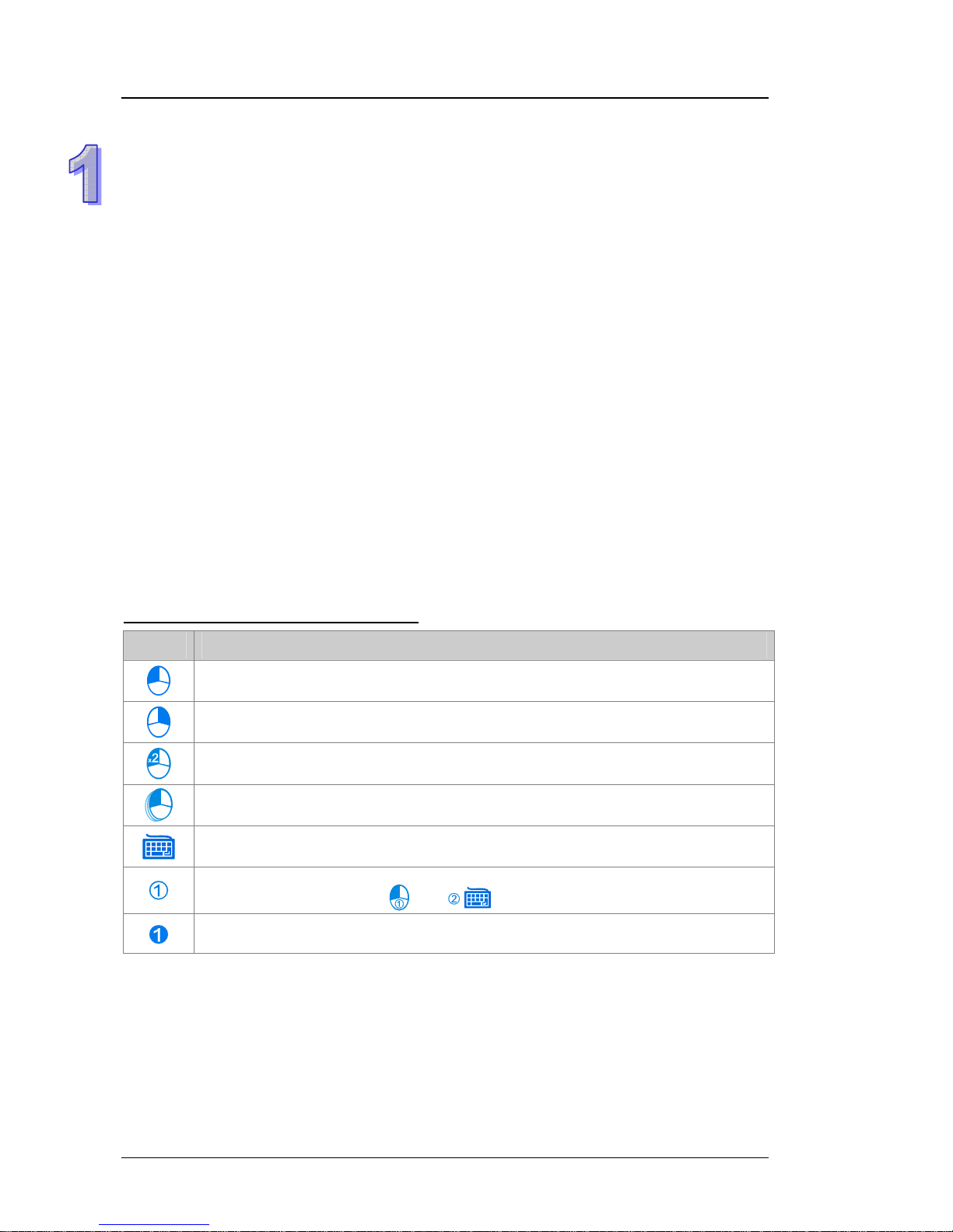
The graphic representations in the manual
Graph Significance
Clicking the left mouse button
Clicking the right mouse button
Double-clicking the left mouse button
Pressing and holding the left mouse button, and then moving the mouse without
releasing the button.
Typing with a keyboard
Operating sequence (The graphic representation is used when the operating sequen ce
is mentioned. For example,
and .)
Number used with a picture
1-2
Chapter 1 Introduction
1.2 System Frameworks
The AH500 series programmable logic controll er is a medium type of programmable logic control
system. The execution speed and the memory capacity are increased. Besides, the complete
program development function of function blocks is supported. In order to meet users’ more
advanced application requirements, the AH500 series programmable logic controllers provide more
flexible system extension frameworks. Under such system frameworks, users do not need to use
several CPU modules to control the system because of the fact that there are too many I/O points or
the equipment is too far away. The completeness of the system is retained, and use rs can be more
efficient in developing the projects.
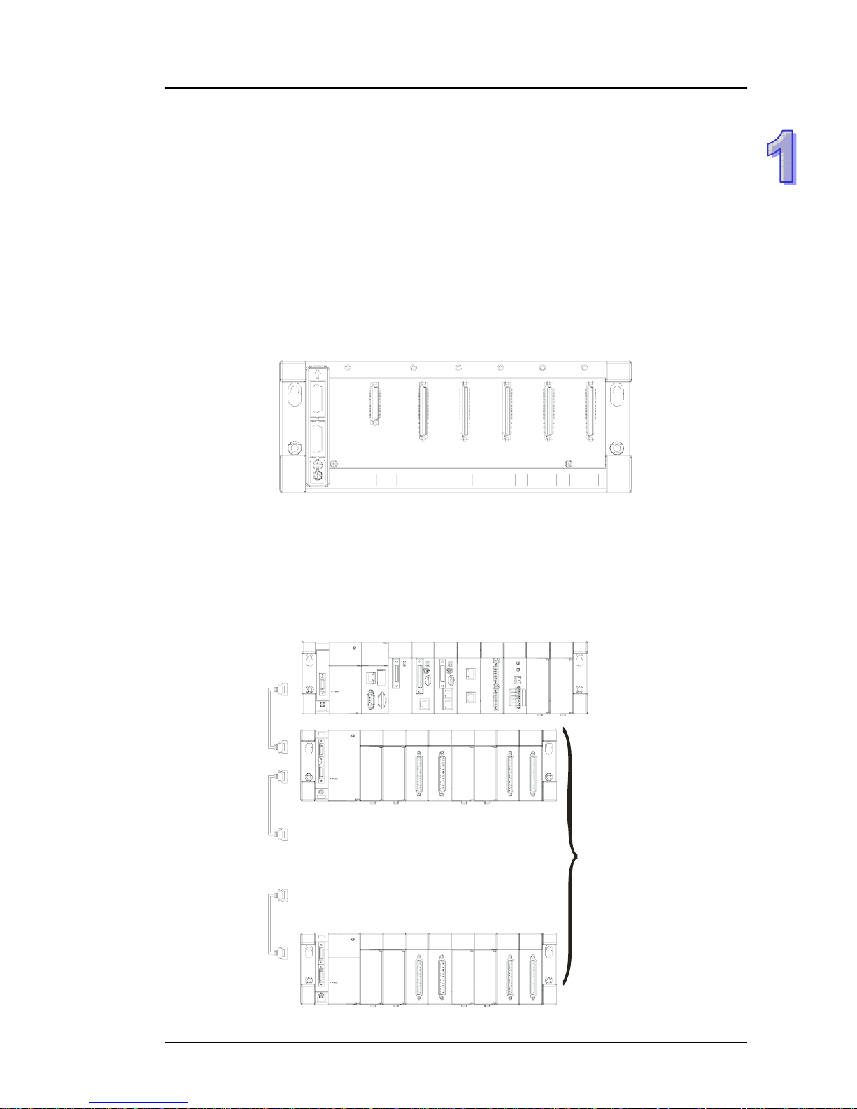
The minimum framework requirement for the AH500 system:
To create the AH500 sy stem, one main backpl ane, one power sup ply module, and one CPU module
are needed for the operation of the CPU module.
Main backplane (four-slot AHBP04M1-5A)
CPU module
Power supply
module
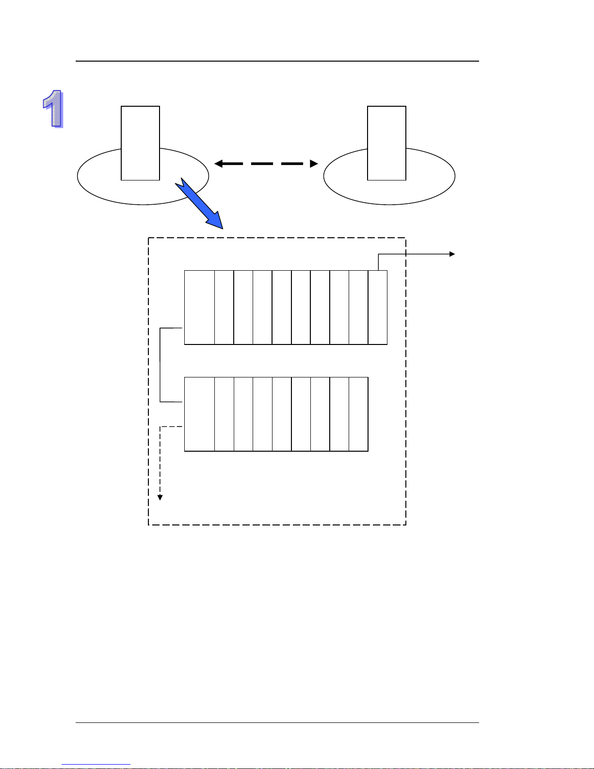
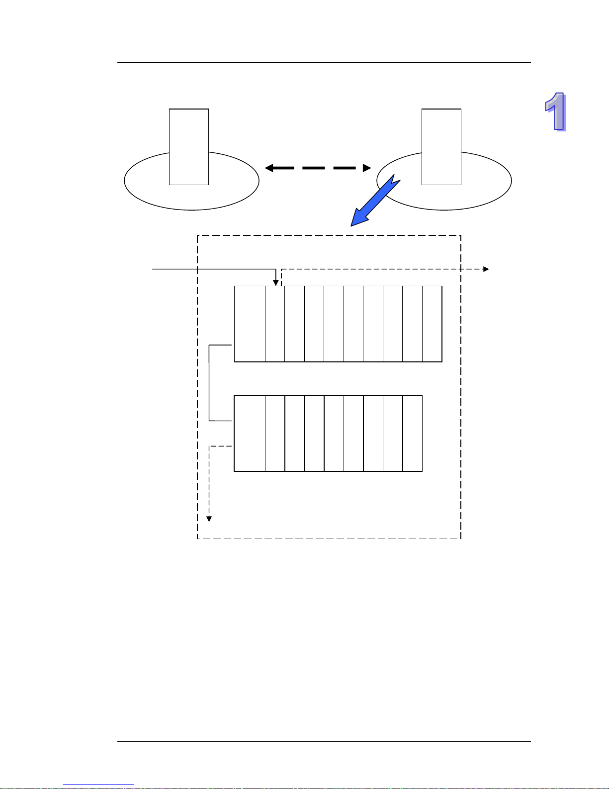
The common framework of the AH500 system (for original equipment manufacturers):
The AH500 system can meet most equipment development re quirements in the application field of
original equipment manufacturers. Generally speaking, one eight-slot main backplane or one
twelve-slot main backplane is chosen. Some advanced equipment can be used with a six-slot
extension backplane or an eight-slot extension backplane under the original framewor k to increase
the number of I/O points and the number of axes, or decrease the wiring cost.
The framework: Rack 1~rack 8
7 backplanes
.
.
.
.
.
.
1-3
AH500 Quick Start
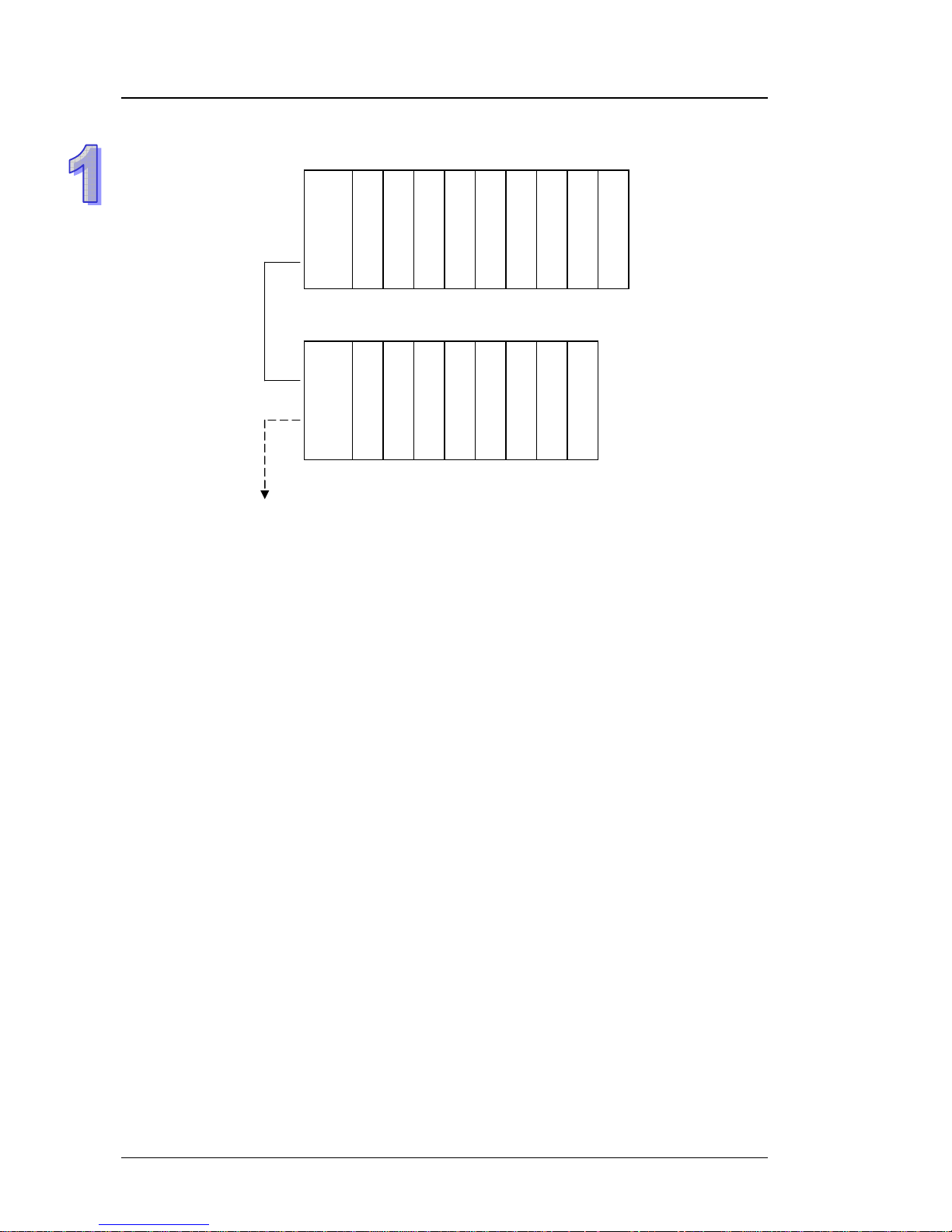
The configuration is as follows.
Power supply
CPU module
Rack 1 (eight-slot main backplane)
Rack 2 (eight-slot extension backplane)
Ei
g
ht racks at most
Motion control module
Network module
Motion control module
Motion control module
Motion control module
Motion control module
Motion control module
Power supply
Digital input module
Digital input module
Digital output module
Analog input module
Temperature
measurement module
Serial communication
module
Note: Owing to the consideration to the data transmission speed, the motion control modules a nd
the network modules (exclusive of the serial communication modules) have to be installed
with the CPU module on the same backplane. Otherwise, the system can not operate
properly.
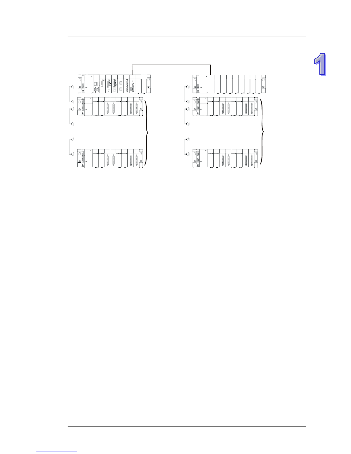
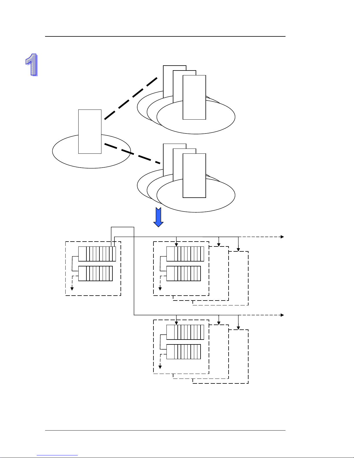
The common framework of the AH500 system (for system integration):
The AH500 system can meet most system control requirement s in the application field of the system
integration. Generally speaking, the system framework is related to the positions of the equipments.
A control pan el is usually p l aced among the equipments which are concentrated to save the wiring
cost. However, there i s usually more than one concentration point, and the distance between the
concentration points is over 100 meters. If it is necessary for users to place more than two control
panels, the RTU modules are required. The re mote framework of the AH5 00 system not only fills the
remote requirement, but also is combined with the extension of the local I/O. Under most conditions,
a control panel instead of a backplane can be regarded as a remote I/O station. In addition, the
backplanes, the power supply modules, and other modules are compatible with one another. The
convenience of planning the system is increased, and the difficulty of choosing the products is also
decreased.
1-4
Chapter 1 Introduction
System framework: Rack 1~rack 8+RTU modules
.
.
.
.
.
.
.
.
.
.
.
.
...
Remote I/O
7 backplanes
7 backplanes
Note: Users are provided with the special cables to connect the extension backplanes. T he length of
a special cable can be up to 100 meters. They are also provided with the fiber cables which
are used with the special adapters. The length of a fiber cable can be up to 2 kilometers.
1-5
AH500 Quick Start
System planning 1
Control panel
Concentration point
Over 100 meters
Rack 1 (eight-slot main backplane)
Master
Master
Slave 1
Control panel
Concentration point
Rack 2 (eight-slot main backplane)
Master
Eight racks at most
Power supply
CPU module
Network module
Digital input module
Digital input module
Digital input module
Digital input module
Digital input module
Digital input module
Remote master
Power supply
Digital output module
Digital output module
Digital output module
Analog input module
Analog input module
Analog input module
Analog output module
Serial communication
module
Slave 1
1-6
Chapter 1 Introduction
System planning 2
Master
Slave 1
Control panel
Control panel
Concentration point
Concentration point
Over 100 meters
Rack 1 (eight-slot main backplane)
Slave 1
Eight racks at most
Sixty-three racks at most
(The remote I/O system is
in use.)
Rack 2
(eight
-slot extension backplane
)
Slave 1
Power supply
Power supply
Analog input module
Analog input module
Analog input module
Analog output module
Analog output module
Analog output module
Serial communication
module
Remote slave
Digital input module
Digital input module
Digital input module
Digital output module
Digital output module
Digital output module
1-7
AH500 Quick Start
System planning 3
Control Panel
設備集中區
Slave 1
Control panel
設備集中區
Slave 2
Control panel
Slave 3
Control panel
設備集中區
Slave 1
Control
p
anel
設備集中區
Slave 2
Control
p
anel
Slave 3
Slave 1
Slave 2
Slave 3
Slave 1 Slave 2
Slave 3
Master
Control panel
Concentration point
Concentration point
Concentration point
Master
Note: The remote masters in DeviceNet are the network modules. They have to be inst alle d with the
CPU modules on the same backplane. A CPU module can support eight masters, and a
master can be connected to sixty-three slaves. Besides, a slave can be connected to seven
1-8
Chapter 1 Introduction
extension backplanes at most.
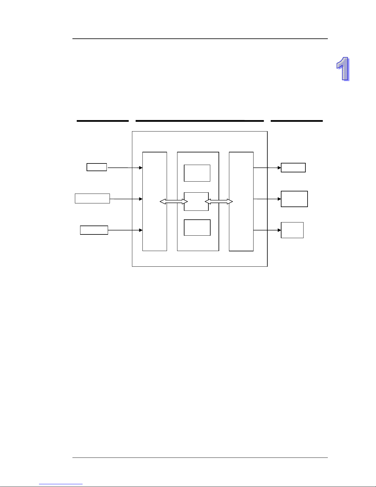
1.3 Operation of the CPU module
The CPU module is the nucleus of the AH500 system. It is responsible for not only the execution of
the logic program, but also the data exchange and the processing of the communication data. The
relation between the AH500 system and the external devices are illustrated below.
System
operation
I/O
refresh
Program
operation
Input module
Output module
CPU module
AH500 system
Switch
Relay
A
C motor
drive
Temperature
Pressure
Electric
valve
External input
device
External output
device
The operation of the CPU module is illustrated above. The system procedures related to the
initialization, the diagnosis, and the communication, and the program procedures related to the
external interrupts and timed interrupts are simplified. Users can refer to other manuals for more
information. The operation of the CPU module is described below.
1-9
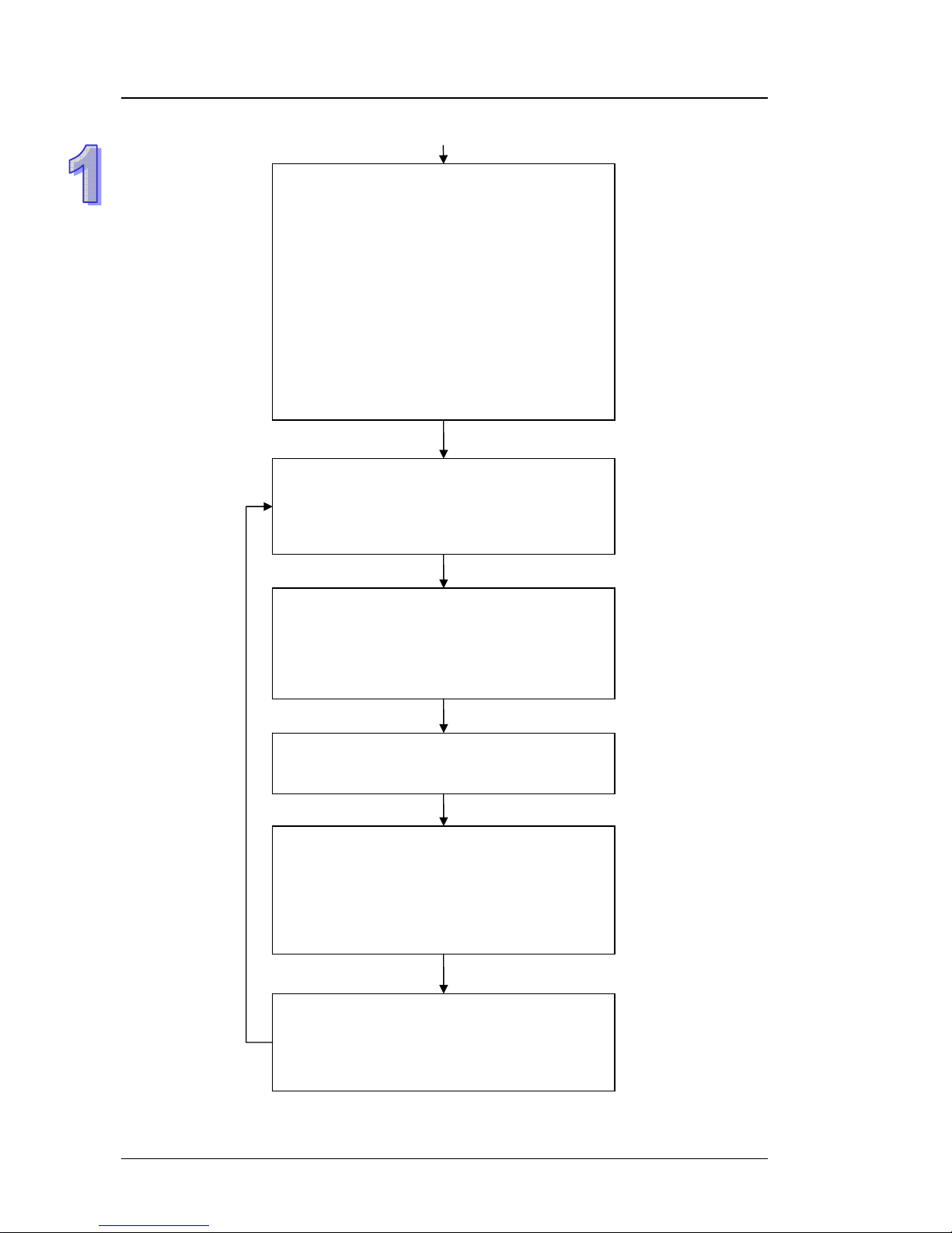
AH500 Quick Start
The CPU module is supplied with power.
The system enables the initialization.
y The non-latched memory is initialized.
y The user program is checked.
y The parameters in the CPU module are
checked.
y The parameters in the module table are
checked.
y The module table in the CPU module is
compared with the actual I/O configuration.
y The I/O setting is downloaded to the I/O
module.
y If the memory card is installed, whether to
execute the system copy procedure or not is
checked.
Diagnosis processing:
y The memory card and other setting are
checked.
y The I/O bus is checked.
y The system parameter is checked.
The data sent to the I/O module is refreshed.
y The data sent to the digital I/O module is
refreshed.
y The data sent to the analog I/O module is
refreshed.
y The data sent to other modules are refreshed.
Program execution:
y The user program is executed.
y The interrupt task is executed.
The data sent from the I/O module is refreshed.
y The data sent from the digital I/O module is
refreshed.
y The data sent from the analog I/O module is
refreshed.
y The data sent from other modules are
refreshed.
Communication service:
y The communication through the CPU module
y The communication through other I/O modules
y The internal communication between the CPU
module and the I/O module
1-10

Chapter 2 Programming
Table of Contents
2.1 Preparations ..............................................................................................2-2
2.1.1 Hardware............................................................................................2-2
2.1.2 Software .............................................................................................2-3
2.1.3 Tools and Materials ............................................................................2-3
2.2 Installation .................................................................................................2-3
2.2.1 Installing Modules...............................................................................2-3
2.2.2 Installing Removable Terminal Blocks ................................................2-4
2.3 Wiring ........................................................................................................2-6
2.3.1 Wiring the Power Supply Module .......................................................2-7
2.3.2 Wiring the Digital Input Module...........................................................2-9
2.3.3 Wiring the Digital Output Module........................................................2-9
2.3.4 Wiring the Analog Input/Output Module............................................2-10
2.3.5 Supplying Power ..............................................................................2-10
2.4 Exemplification ........................................................................................2-11
2.5 Creating Projects.....................................................................................2-12
2.6 Hardware Configuration...........................................................................2-14
2.7 Creating Global Symbols.........................................................................2-19
2.8 Creating Function Blocks.........................................................................2-20
2.9 Creating Main Programs..........................................................................2-29
2-1
AH500 Quick Start
2.1 Preparations
2.1.1 Hardware
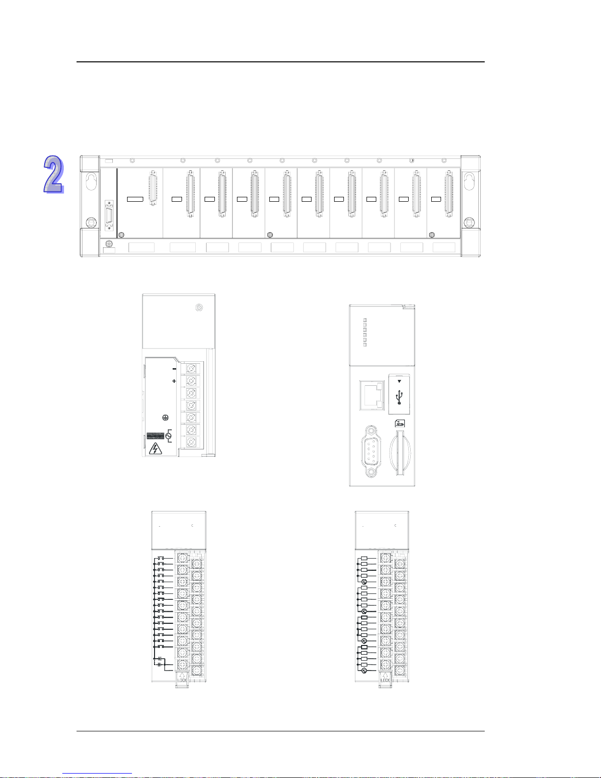
The hardware needed in the example is as follows.
1. Eight-slot main backplane
AHBP08M1-5A x 1
POWER CPU I/O0 I/O1 I/O2 I/O3 I/O4 I/O5 I/O6 I/O7
2. Power supply module
AHPS05-5A x 1
PS05
POWER
NC
FG
INPUT
VS
VS
LG
N
L
3. CPU module (with the built-in network
function)
AHCPU530-EN x 1
CPU530-EN
RUN
ERROR
BUS FAUL T
SYSTEM
COM
Ethernet
COM
USB
4. Digital input module (16 inputs)
AH16AM10N-5A x 1
7
10
12
11
9
8
6
5
4
3
2
15
14
6
7
13
S/S
24VDC 5mA
1
0
16AM10N
023154
S/S
98110 11 12 13 14 5
5. Digital output module (16 outputs)
AH16AN01R-5A x 1
16AN01R
10432
567
L
L
L
L
4
5
3
2
L
COM0
12
COM1
L
7
L
L
L
L
L
13
14
15
L
6
11
COM2
24VDC
/24 0V AC 2A
COM3
L
L
L
8
10
9
L
1
0
1110 1413 151289
2-2
Chapter 2 Programming
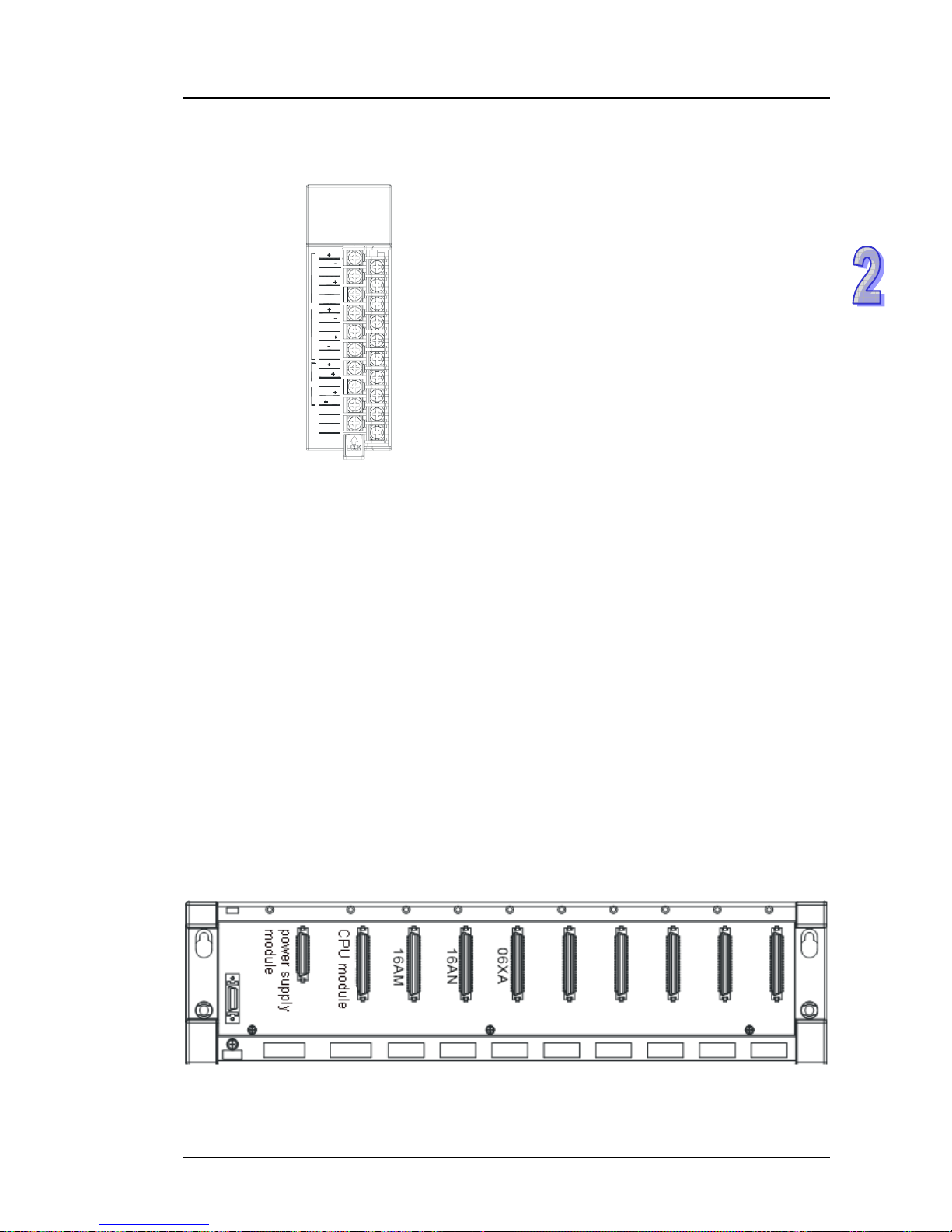
6. Analog input/output module (6 channels)
AH06XA-5A x 1
V2
V1
AI
R1
R0
V0
V1
V3
V3
R3
R2
V2
V0
ERROR
RUN
10V,20mA
10V,0/4~20mA
FE
UP
V0
V1
I1
ZP
COM
AO
I0
06XA
2.1.2 Software
The software needed in the example is as follows.
z ISPSoft version 2.0 or above
z COMMGR version 1.0 or above
2.1.3 Tools and Materials
The tools and the materials need in the example are as follows.
z A personal computer in which the software mentioned above is installed
z A 100~240 V AC and 50/60 Hz power supply socket
z A 24 V DC power supply
z A cable
z A screwdriver
z An USB cable or a network cable (If users want to connect the Ethernet port or the COM port
(RS-232/RS-485) on the CPU module to the computer, they can refer to section 2.3.2 in
ISPSoft User Manual for more information. If users want to know more about installing the
USB driver, they can refer to appendix A in AH500 Operation Manual.)
z If necessary, users can prepare the accessories such as a switch and a bulb (to simulate the
activity of the external equipment).
2.2 Installation
2.2.1 Installing Modules
Please install the modules on the main backplane, as illustrated below.
Connect the module to the connector on the backplane, make sure that the module is installed on
the backplane properly, and tighen the the screw.
2-3
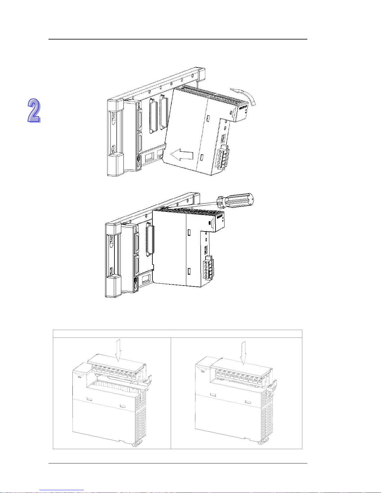
AH500 Quick Start
1. Insert the projection under the module into the hole in the backplane.
2. Push the module in the direction indicated by the arrow until it clicks.
3. Tighten the screw on the module.
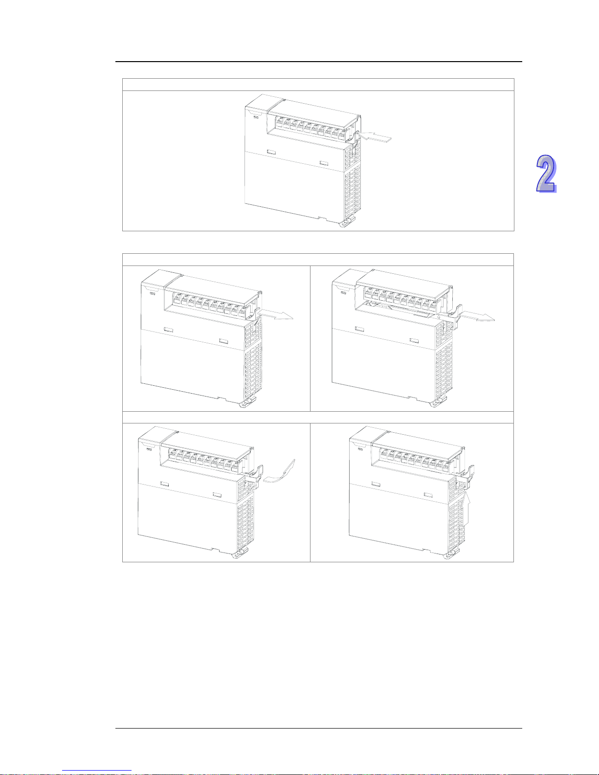
2.2.2 Installing Removable Terminal Blocks
Please install the removable terminal block on the module, as illustrated below.
z
Installation
1. Level the terminal block at the printed circuit board, and press it into the module.
2-4
Chapter 2 Programming
2. Press the clip in the direction indicated by the arrow.
z
Removal
1. Pull the clip in the direction indicated by the arrow.
2. Pull up the clip.
2-5
AH500 Quick Start
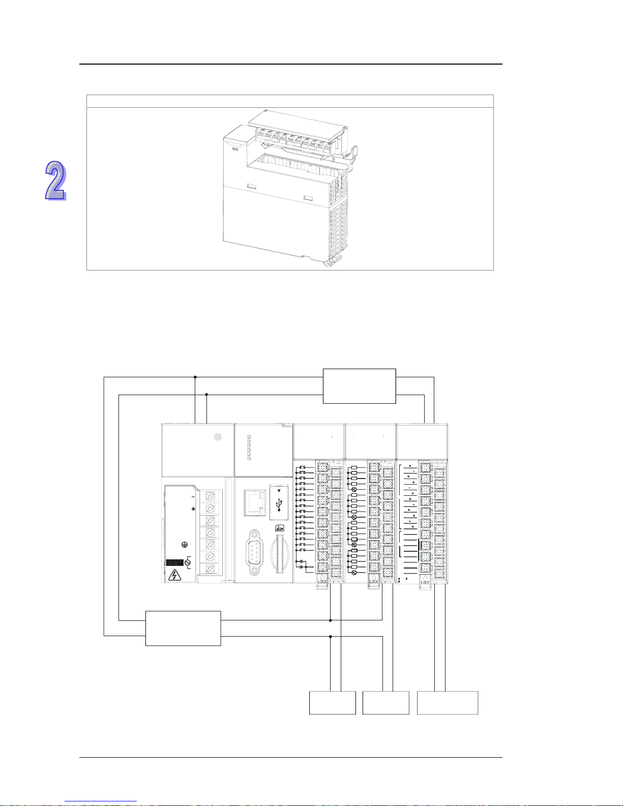
3. The terminal block is removed.
2.3 Wiring
After the modules are installed, the wiring of the modules follows. In order for the following example
to proceed smoothly, the power supply module and the analog module have to be wired. Be sure to
cut off the power supply before wiring the modules. To lend convenience and reality to the
simulation, the signal lines can be connected to the switch and the bulb according to the personal
needs. The rough framework is as follows.
V2
VI1
A
I
I1
I0
VI0
V1
V3
VI3
I3
I2
VI2
V0
ERROR
RUN
±
10V,±20mA
±
10V,0/4~20mA
SG
UP
VO0
VO1
IO1
ZP
A
G
A
O
IO0
06XA
7
10
12
11
9
8
6
5
4
3
2
15
14
6
7
13
S/S
24VDC 5mA
1
0
16AM10N
023154
S/S
981510 11 12 13 14
16AN01R
10432567
L
L
L
L
4
5
3
2
L
COM0
12
COM1
L
7
L
L
L
L
L
13
14
15
L
6
11
COM2
24VDC
/
240VAC 2A
COM3
L
L
L
8
10
9
L
1
0
1110 1413 151289
PS05
POWER
NC
FG
INPUT
VS
VS
LG
N
L
CPU530-EN
RUN
ERROR
BUS FAULT
SYSTEM
COM
Ethernet
COM
USB
L
N
+
-
Bulb
Signal
simulator
+
-
ZP
UP
S/S COM
100~240 V A
C
Switch
DC 24 V
power supply
DC 24 V
power supply
2-6

Chapter 2 Programming
The wiring of the modules is described in detail below. (Please refer to AH500 Hardware Manual for
more information.)
2.3.1 Wiring the Power Supply Module
z The alternating-current input voltage is within the range between 100 V AC and 240 V AC.
Please connect the power supply to the terminals L and N.
If the 110 V AC or the 220 V AC
power supply is connected to the input terminals VS+ and VS-, the PLC will be
damaged.
z In order to ensure that the 24 V DC external power supply is provided stably, it can be
connected to VS+ and VS-. If the PLC detects that the voltage of the external power supply is
lower than the working voltage, users can write a protective program. (Please refer to section
6.6 in AH500 Operation Manual for more information.)
z The length of the wire connecting with the ground is 1.6 millimeters.
z If the power cut lasts for less than 10 milliseconds, the PLC keeps running without being
affected. If the power cut lasts for long, or if the voltage of the power supply decreases, the
PLC stops running, and there is no output. When the power supply returns to normal, the PLC
resumes. (Users have to notice that there are latched auxiliary relays and registers in the PLC
when they write the program.)
z Please use the single-core cable or the twin-core cable. The diameter of the cable used should
be with the range between 12 AWG and 22 AWG. The torque applied to the terminal screw
should be within the range between 5 kg-cm (4.3 Ib-in) and 8 kg-cm (6.9 Ib-in). Please use the
copper conducting wire. The temperature of the copper conducting wire should be 60/75°C.
z Safety wiring: The PLC controls many devices, and the activity of any device affects the
activity of other devices. If a device breaks down, the whole automatic control system goes out
of control, and the danger occurs. The protection circuit is as follows.
2-7

AH500 Quick Start
①
Alternating-current power supply: 100~240 V AC, and 50/60 Hz
②
Circuit breaker
③
Emergency stop: The emergency stop button can be used to cut off the power when an
emergency occurs.
④
Power indicator
⑤
AC power load
⑥
Fuse (2A)
⑦
The ground impedance is less than 100 Ω.
○
8
Direct-current power supply: 24 V DC
2-8
 Loading...