

Delta AHCPU510-RS2, AHCPU500-RS2, AHCPU500-EN, AHCPU510-EN, AHCPU520-RS2 Hardware Manual
...Page 1
Page 2

Chapter 1 Product Introduction
Table of Contents
1.1 Overview...................................................................................................1-2
1.1.1 Related Manuals ................................................................................1-2
1.1.2 Model Description...............................................................................1-2
1.2 Characteristics...........................................................................................1-7
1-1
Page 3

AH500 Hardware Manual
1.1 Overview
This manual introduces the programming of the AH500 series pro grammable logic controllers, the
basic instructions, and the applied instructions. This manual introduces the electrical specifications
for the AH500 series programmable logic controllers, the appearances, the dime nsions, and etc.
1.1.1 Related Manuals
The related manuals of the AH500 series programmable logic controllers are co mposed of the
following.
z AH500 Quick Start
It guides u
sers to use the system before they read the related manuals.
z
AH500 Programming Manual
It introduce
s the programming of the AH500 series programmable logic controllers, the basic
instruction
s, and the applied instructions.
z ISPSoft
User Manual
It introduces the use of ISPSoft, the programming language (Ladder, IL, SFC, FBD, and ST),
the conc
ept of POUs, and the concept of tasks.
z AH500 Ha
rdware Manual
It introduces electrical specifications, appearan
ces, dimensions, and etc.
z AH500 Operation Manual
It introduce
s functions of CPUs, devices, module tables, troubleshooting, and etc.
z
AH500 Module Manual
It introduce
s the use of special I/O modules. For example, network modules, analog I/O
modules
, temperature measurement modules, motion control modules, and etc.
z AH500 Motion Control Module Manual
It introduce
s the specifications for the motion control modules, the wiring, the instructions, and
the functions.
z PMSoft User Manual
It introduce
s the use of PMSoft, including the editing mode, the co
nnection, and the password
setting.
1.1.2 Model Description
Classification Model Name Description
Power supply
module
AHPS05-5A
100~240 V AC
50/60 Hz
AHCPU500-RS2
It is a basic CPU module with two built-in RS-485 ports, one
built-in USB po
rt, and one built-in SD interface. It supports
768 inputs/outputs. The p rogram capacity is 16 ksteps.
AHCPU500-EN
It is a basic CPU module with one built-in Ethernet port, one
built-in RS-48
5 port, one built-in USB port, and one built-in
SD interface. It supports 768 inputs/outputs. The program
capacity is 16 ksteps.
AHCPU510-RS2
It is a basic CPU module with two built-in RS-485 ports, one
built-in USB po
rt, and one built-in SD interface. It supports
1280 inputs/outputs. Th e program capacity is 64 ksteps.
AHCPU510-EN
It is a basic CPU module with one built-in Ethernet port, one
built-in RS-48
5 port, one built-in USB port, and one built-in
SD interface. It supports 1280 inputs/outputs. The program
capacity is 64 ksteps.
CPU module
AHCPU520-RS2
It is a basic CPU module with two built-in RS-485 ports, one
built-in USB po
rt, and one built-in SD interface. It supports
2304 inputs/outputs. Th e program capacity is 128 ksteps.
1-2
Page 4

Chapter 1 Product Introduction
Classification Model Name Description
AHCPU520-EN
It is a basic CPU module with one built-in Ethernet port, one
built-in RS-48
5 port, one built-in USB port, and one built-in
SD interface. It supports 2304 inputs/outputs. The program
capacity is 128 kstep s.
AHCPU530-RS2
It is a basic CPU module with two built-in RS-485 ports, one
built-in USB po
rt, and one built-in SD interface. It supports
4352 inputs/outputs. Th e program capacity is 256 ksteps.
CPU module
AHCPU530-EN
It is a basic CPU module with one built-in Ethernet port, one
built-in RS
-48
5 port, one built-in USB port, and one built-in
SD interface. It supports 4352 inputs/outputs. The program
capacity is 256 kstep s.
AHBP04M1-5A Four-slot main backplane for a CPU /RTU rack
AHBP06M1-5A Six-slot main backplane for a CPU/RTU rack
AHBP08M1-5A Eight-slot main backplane for a CPU/RTU rack
Main
backplane
AHBP12M1-5A Twelve-slot main ba ckplane for a CPU/RTU rack
AHBP06E1-5A Six-slot extension backplane for a CPU/RTU extensio n rack
Extension
backplane
AHBP08E1-5A
Eight-slot extension backplane for a CPU/RTU extension
rack
AH16AM10N-5A
24 V DC
5 mA
16 inputs
Terminal block
AH32AM10N-5B
24 V DC
5 mA
32 inputs
DB37 connector
AH64AM10N-5C
24 V DC
3.2 mA
64 inputs
Latch connector
AH16AM30N-5A
100~240 V AC
4.5 mA/9 mA (100 V and 50 Hz)
16 inputs
Terminal block
AH16AN01R-5A
240 V AC/24 V DC
2 A
16 outputs
Relay
Terminal block
AH16AN01T-5A
12~24 V DC
0.5 A
16 outputs
Sinking output
Terminal block
Digital
input/output
module
AH16AN01P-5A
12~24 V DC
0.5 A
16 outputs
Sourcing output
Terminal block
1-3
Page 5

AH500 Hardware Manual
Classification Model Name Description
AH32AN02P-5B
12~24 V DC
0.1 A
32 outputs
Sinking output
DB37 connector
AH32AN02T-5B
12~24 V DC
0.1 A
32 outputs
Sourcing output
DB37 connector
AH64AN02T-5C
12~24 V DC
0.1 A
64 outputs
Sinking output
Latch connector
AH64AN02P-5C
12~24 V DC
0.1 A
64 outputs
Sourcing output
Latch connector
AH16AN01S-5A
110/220 V AC
0.5 A
16 outputs
TRIAC
Terminal block
AH16AP11R-5A
24 V DC
5 mA
8 inputs
240 V AC/24 V DC
2 A
8 outputs
Relay
Terminal block
AH16AP11P-5A
24 V DC
5 mA
8 inputs
12~24 V DC
0.5 A
8 outputs
Sinking output
Terminal block
Digital
input/output
module
AH16AP11T-5A
24 V DC
5 mA
8 inputs
12~24 V DC
0.5 A
8 outputs
Sourcing output
Terminal block
1-4
Page 6

Chapter 1 Product Introduction
Classification Model Name Description
AH04AD-5A
Four-channel analog input module
16-bit resolution
0~10 V, 0/1~5 V, -5~+5 V, -10~+10 V, 0/4~20 mA, and
-20
~
+20 mA
Conversion time: 150 us/channel
AH08AD-5B
Eight-channel analog input module
16-bit resolution
0~10 V, 0/1~5 V, -5~+5 V, and -10~+10 V
Conversion time: 150 us/channel
AH04DA-5A
Four-channel analog output module
16-bit resolution
-10~10 V, and 0/4~20 mA
Conversion time: 150 us/channel
AH08DA-5B
Eight-channel analog output module
16-bit resolution
-10~+10V, 0~10V, -5~+5V, and 0/1~5V
Conversion time: 150 us/channel
Analog
input/output
module
AH06XA-5A
Four-channel analog input module
16-bit resolution
0~10 V, 0/1~5 V, -5~+5 V, -10~+10 V, 0/4~20 mA, and
-20
~
+20 mA
Conversion time: 150 us/channel
Two-channel analog output module
16-bit resolution
-10~10 V, and 0/4~20 mA
Conversion time: 150 us/channel
AH04PT-5A
Four-channel four-wire/three-wire RT
D temperature sensor
Sensor type: Pt100/Pt1000/Ni100/Ni1000 sensor, and
0~300 Ω inp
ut impedance
16-bit resolution: 0.1 ℃/0.1
℉
Four-wire conversion time: 150 ms/channel
Three-wire conversion time: 300 ms/channel
AH04TC-5A
Four-channel thermocouple temperature sensor
Sensor type: J, K, R, S, T, E, N, and -150~+150 mV
24-bit resolution: 0.1 ℃/0.1
℉
Conve
rsion time: 200 ms/channel
Temperature
measurement
module
AH08TC-5A
Eight-channel thermocouple temperature sensor
Sensor type: J, K, R, S, T, E, N, and -150~+150 mV
24-bit resolution: 0.1 ℃/0.
1
℉
Conversion time: 200 ms/channel
AH02HC-5A
Two-channel high-sp eed counter modul e
200 kHz
AH04HC-5A
Four-channel high-speed counter module
200 kHz
AH05PM-5A Two-axis pulse train motion control m odule (1 MHz)
AH10PM-5A
Six-axis pulse train motion control module
(Four axes: 1 MHz; Two axes: 200 kHz)
Motion control
module
AH20MC-5A
Twelve-axis DMCNET (Delta Motion Control Network)
motion contro
l module (10 Mbps)
1-5
Page 7

AH500 Hardware Manual
Classification Model Name Description
AH10EN-5A
It is an Ethernet master module with two built-in Ethernet
ports
, and supports a Modbus TCP master.
AH10SCM-5A
It is a serial communication module with two
RS-485/RS
-422 ports, and supports Modbus and the UD
link protocol.
There is isolation between two parts of communication, and
there is is
olation between two parts of power.
Network
module
AH10DNET-5A
It is a DeviceNet network module. It can function as a
master
or a slave. The maximum communication speed is 1
Mbps.
RTU module AHRTU-DNET-5A RTU module for DeviceNet
AHACAB06-5A
0.6 meter extension cable for connecting an extension
backplane
AHACAB10-5A
1.0 meter extension cable for connecting an extension
backplane
AHACAB15-5A
1.5 meter extension cable for connecting an extension
backplane
Extension
cable
AHACAB30-5A
3.0 meter extension cable for connecting an extension
backplane
DVPACAB7A10
1.0 meter I/O extension cable (latch connector) for
AH64AM10N-5C
DVPACAB7B10
1.0 meter I/O extension cable (latch connector) for
AH64AN02
T-5C and AH64AN02P-5C
DVPACAB7C10 1.0 meter I/O extension cable (DB37)
DVPACAB7D10
1.0 meter I/O extension cable for AH0 4HC-5A and
AH20MC-5A
I/O extension
cable
DVPACAB7E10
1.0 meter I/O extension cable (latch connector) for
AH10PM-
5A
DVPAETB-ID32A
I/O external terminal module for AH64A M10N-5C
32 inputs
DVPAETB-OR16A
I/O external terminal module for AH64AN02T-5C
16 relay outputs
DVPAETB-OR16B
I/O external terminal module for AH64A N02P-5C
16 relay outputs
DVPAETB-ID32B
I/O external terminal module for AH32A M10N-5B
32 inputs
DVPAETB-OR32A
I/O external terminal module for AH32AN02T-5B
32 relay outputs
DVPAETB-OR32B
I/O external terminal module for AH32A N02P-5B
32 relay outputs
DVPAETB-OT32B
I/O external terminal module for AH32A N02T-5B and
AH32A
N02P
-5B
32 relay outputs
DVPAETB-IO16C
I/O external terminal module for AH04HC-5A and
AH20MC-5A
External
terminal
module
DVPAETB-IO24C I/O external terminal module for AH10P M-5A
Space module AHASP01-5A Space module used for an empty I/O slot
1-6
Page 8
Chapter 1 Product Introduction
1.2 Characteristics
AH500 system
The characteristics of the AH500 series CPU module are as follows.
(1) High efficiency
z The AH500 series CPU module adopts a 32-bit hig
h-speed processor. The instructions are
executed at a speed of 0.3 milliseconds per 1 ksteps. (Fifty percent of the instructions are
basic instructions, and fifty percent of the instructions are applied instructions.)
(2) Supporting more inputs and outputs
z The AH500 series CPU module supports up to 4,352 local digital I/O or 512 analog I/O.
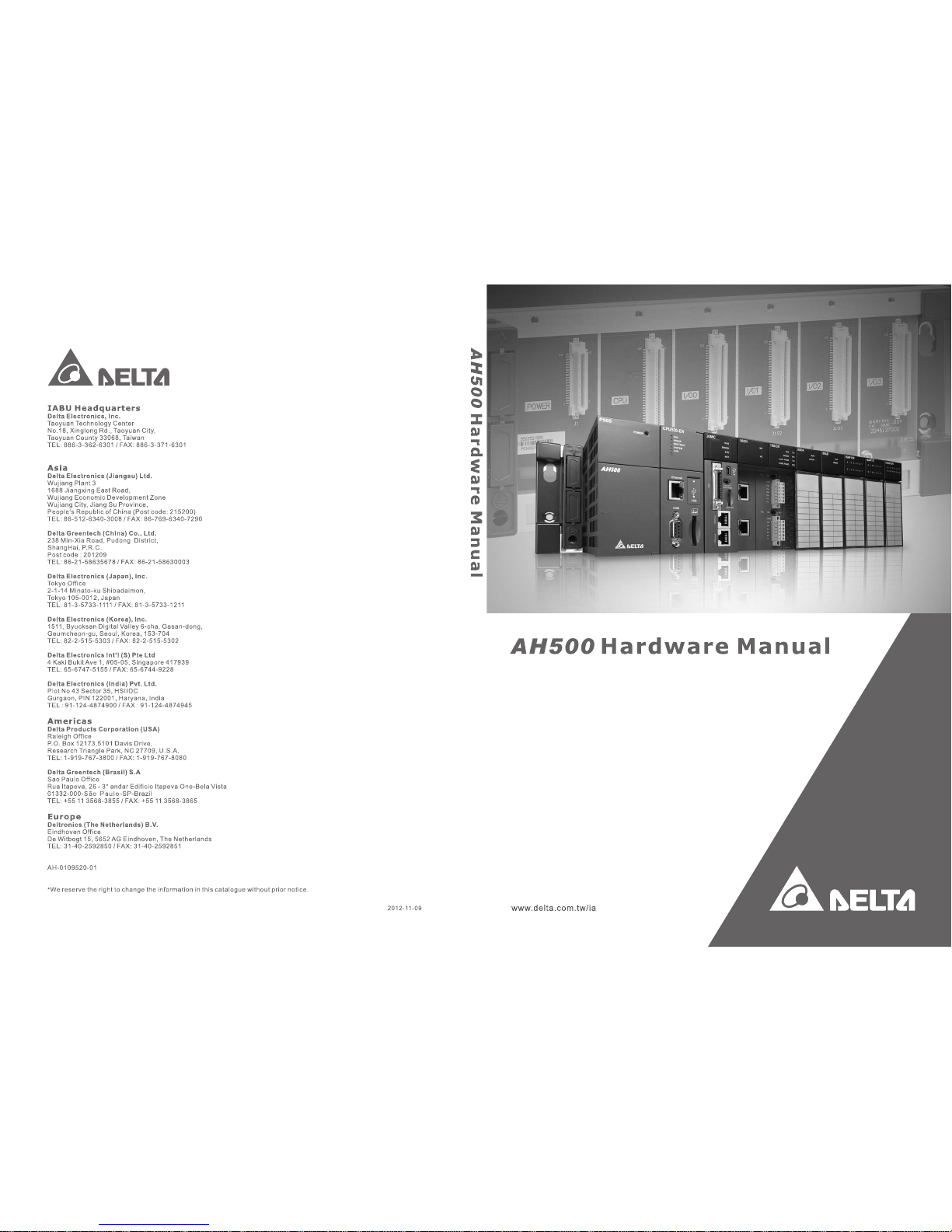
z A complete AH500 system consists of eight backpl
anes at most, including a main backplane.
Eight I/O modules at most can be installed on a backplane. Theref ore, for the AH500 series
CPU, 64 digital input/output modules at most or 64 analog input/output modules at most can
be installed.
z Eight RTU modules at most can be installed on the main backplane. 128,000 remote digital
I/O, or 4,000 remote a
nalog I/O at most are supported.
(3) Multiple I/O modules
z
The I/O modules supported by the AH500 series CPU module are digital input/output
module
s, analog input/output modules, temperature measurement modules, network
modules, motion control modules, and RTU modules.
Module Description
Digital
input/output
module
Digital input/output
AH16AM10N-5A, AH32AM10N-5B, AH64AM10N-5C, AH16AM30N-5A,
AH16A
N01
R-5A, AH16AN01T-5A, AH16AN01P-5A, AH32A N02T-5B,
AH32AN02P-5B, AH64AN02T -5C, AH64AN02P-5C, AH16AN01S-5A,
AH16AP1 1R-5A, AH16AP1 1T -5A, and AH16AP11P-5A
Analog
input/output
module
Analog input/output
AH04AD-5A, AH08AD-5B, AH04DA-5A, AH08DA-5B,
and AH06XA-5A
1-7
Page 9
AH500 Hardware Manual
Module Description
Temperature
measurement
module
Measuring the temperature
AH04PT-5A, AH04TC-5A, and AH08TC-5A
Motion
control
module
Controlling the motion
AH02HC-5A, AH04HC-5A, AH05PM-5A, AH10PM-5A, and AH20MC-5A
Network
module
Extending the communication interface (*There are multiple interfaces. All
network m
odules can be installed on the main backplane except
AH10SCM-5A.)
AH10EN-5A, AH10SCM-5A, and AH10DNET-5A
RTU module
It is installed on the main backplane as a remote terminal unit. (*It
sup
port
s multiple communication interfaces.)
AHRTU-DNET-5A
(4) Larger program capacity and memory
z The program capacity of the AH500 series CPU modules can be up to 256 ksteps. Users do
not need to u
se a more advanced CPU if the program capacity becomes large.
z The AH500 series CPU module has 64 kwords of me mory. Besides, users can declare up to
1024 fun
ction blocks.
(5) Supporting IEC 61131-3
z The AH500 series CPU module supports IEC 61131-3.
1-8
Page 10
Chapter 1 Product Introduction
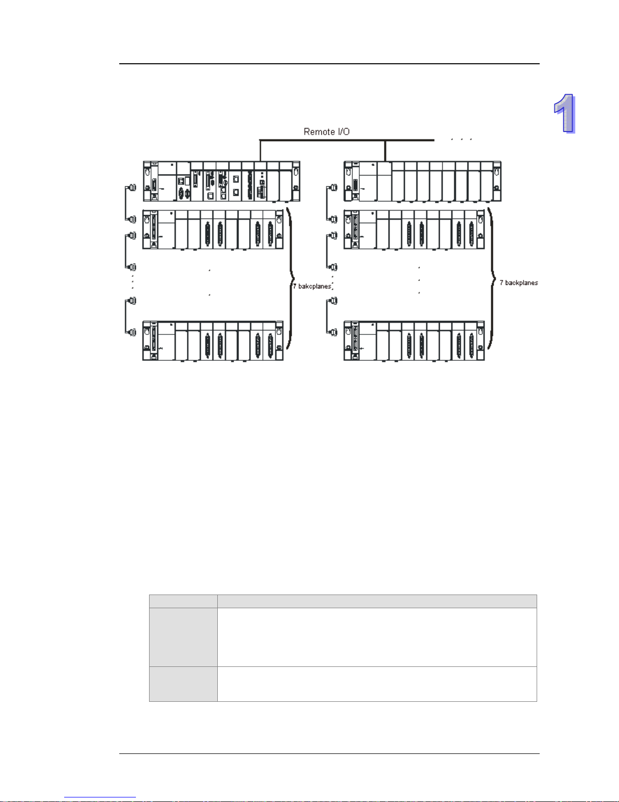
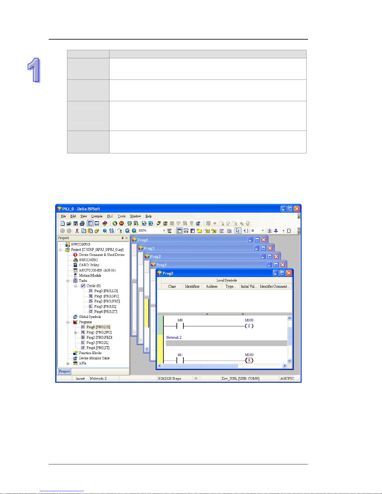
z The programming languages which are supported are instruction lists (IL), structured texts
(ST), ladder diagrams (LD), sequential function charts (SFC), and function bl ock diagrams
(FBD).
z Users can select a programming language according to their preference and the
conve
nience. The programming languages support one another so that the programs written
by different users are related.
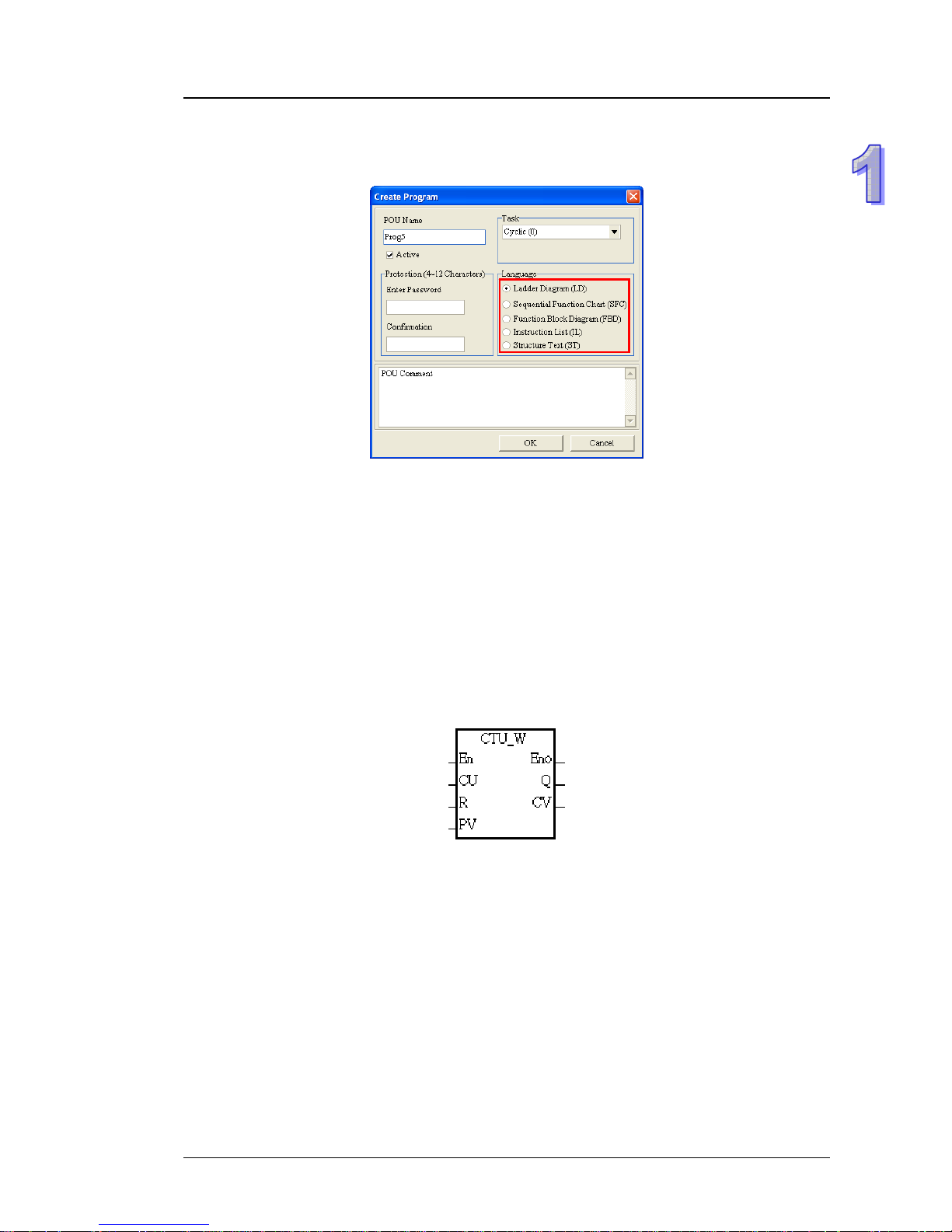
(6) Strong function block
z Not only the standard IEC61131-3 function blocks are supported, but also the convenient
function bl
ocks provided by Delta Electronics, Inc. are supported. Users can write the
program frequently executed in a function block so that the program becomes more
structured and can be executed more conveniently.
z The symbol for a function block in a ladder diagram i
s like an Integrated circuit (IC) in a circuit
diagram. Owing to the fact that the ladder diagram is based on the traditional circuit diagram,
the operation of a function block is quite similar to the function of an integrated circuit. Users
only need to send the signal to the corresponding input of the function block, and they can
receive the signal or state which is required. During the whole process, users do not need to
consider the processing procedure inside the function block.
z A function block is a program element equipped with the operation f
unction. It is similar to a
subroutine, and is a type of POU (Program Organization Unit). It can not operate by itself,
and has to be called through the program POU. After the related parameters are transmitted,
the function defined by a function block is executed. Besides, the final operation result can be
sent to the device or variable used in the superior POU after the execution of the function
block is complete.
z The encryption function supported by ISPSoft provides the secrecy of function bl
ocks for
special businesses. The program inside a function block can not be learned, and the patent
of a business will not be infringed.
1-9
Page 11
AH500 Hardware Manual
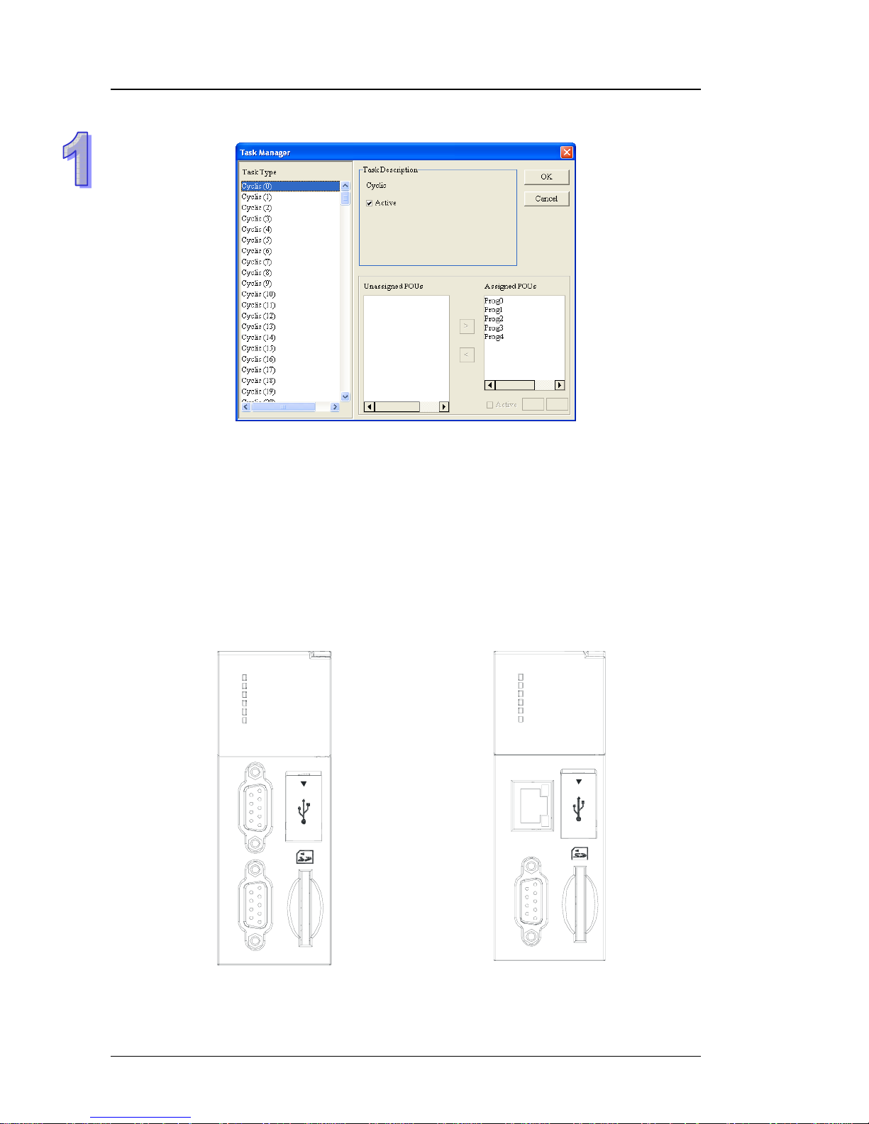
(7) Task
z The programs can be assigned to 283 tasks at mo
st. Among the 288 t asks, 32 tasks are
cyclic tasks, 32 tasks are I/O interrupts, 4 tasks a re timed interrupts, 2 tasks are
communication interrupts, 1 task is an external 24 V low-volt age interrupt, and 212 tasks are
user-defined tasks.
z Users can enable and disable a task during the execu
tion of a program by means of TKON
and TKOFF.
(8) Increasing the efficiency of configuring the hard
ware through an USB cable and ISPSoft
z The AH500 series CPU module provides a standa
rd USB 2.0 interface. USB 2.0 increases
the data transfer rate, and decreases the time it takes to download the program, monitor th e
program and configure the hardware. Besides, users do not need to buy a communication
cable for the CPU module. They can use a general USB cable to connect to the AH500 se ries
CPU module.
(9) Serial control interface
w
ith multiple functions
CPU530-RS2
RUN
ERROR
BUS FAULT
SYSTEM
COM1
COM2
C
O
M
C
O
M
2
1
USB
CPU530-EN
RUN
ERROR
BUS FAUL T
SYSTEM
COM
Ethernet
COM
USB
z AHCPU500/510/520/530-RS2 provides two DB9 se
rial control interfaces, i.e. COM1 and
COM2.
z AHCPU500/510/520/530-EN provides one DB9 seri
al control interface, i.e. COM.
1-10
Page 12
Chapter 1 Product Introduction
z Users can set the DB9 serial control interface to RS232, RS485, or RS422 according to the
application environment. The data transfer rate can be increa sed from 9600 bps to 1 Mbps.
z After users set the PLC Link in ISPSoft, they can exchange the data with a device on the
RS-485 network through the RS-485 serial control interface, and do not need to write any
program.
(10) High-speed Ethernet communication interface
z AHCPU500/510/520/530-EN is equipped with a 10/10
0 M Ethernet communication interface,
and supports emails, webs, and socket services.
z After users set the Ether Link in ISPSoft, they can exchange the dat
a with a device in the
Ethernet network through the Ethernet communication interface, and do not need to write any
program.
z The status or the error message related to the system is sent to users’ email boxes
immediately
. Users do not need to be on the spot to understand the problem.
(11) Memory card
z The memory card has the following functions.
System backup:
The user program, the CPU paramete
rs, the module table, the setting value
in the device
System recovery: The user program, the CPU parameters, the mod ule table, and the setting
value in the de
vice
Parameter storage: The value in the device
Log storage: The system error log and the system status log
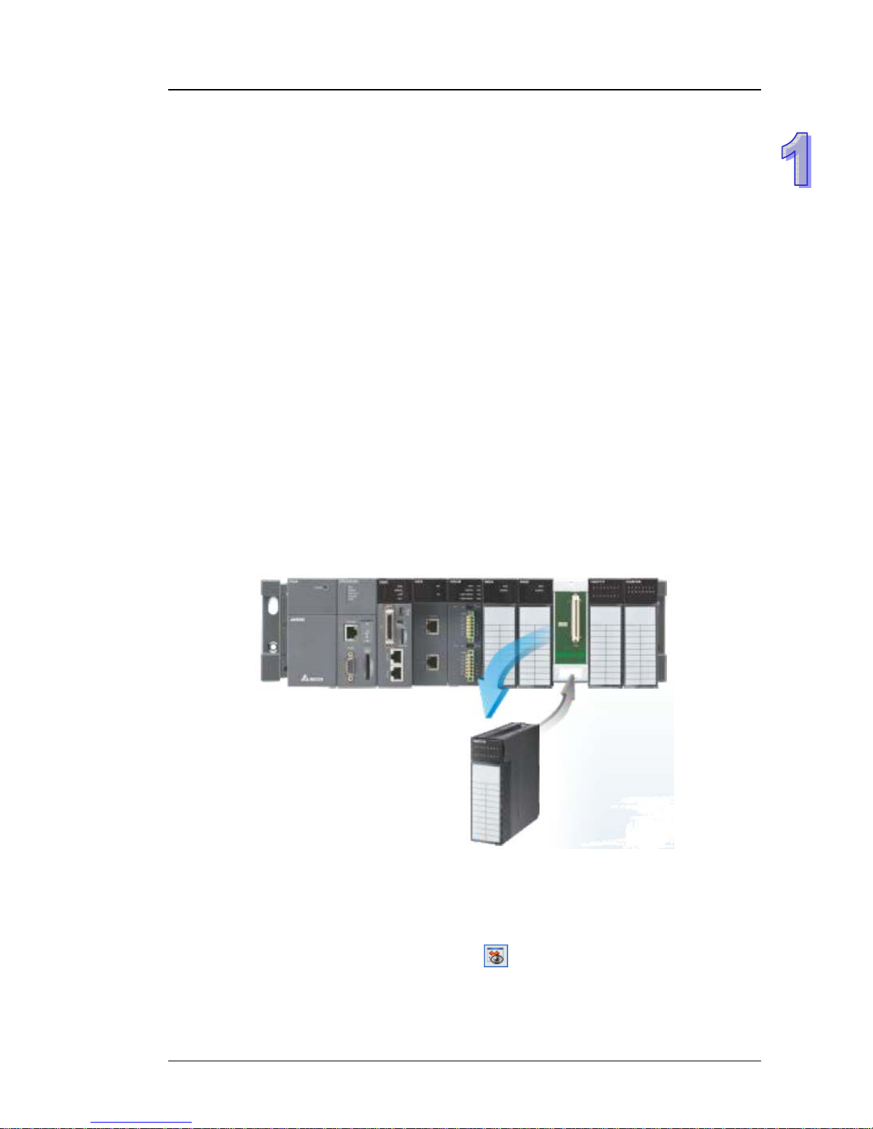
(12) Hot swap
z The AH500 series I/O modules support the on-line uninterruptible hot swap. When the
system run
s, users can replace the module which breaks down without disconnecting the
module. After the module is replaced, the new module runs normally. Users do not need to
set the module manually or switch the state.
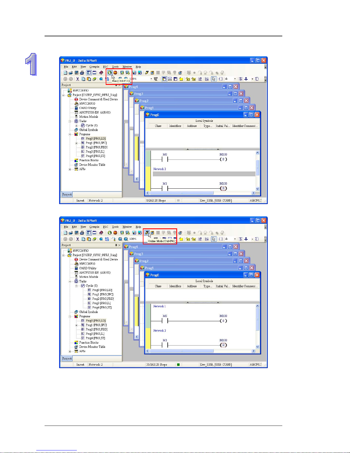
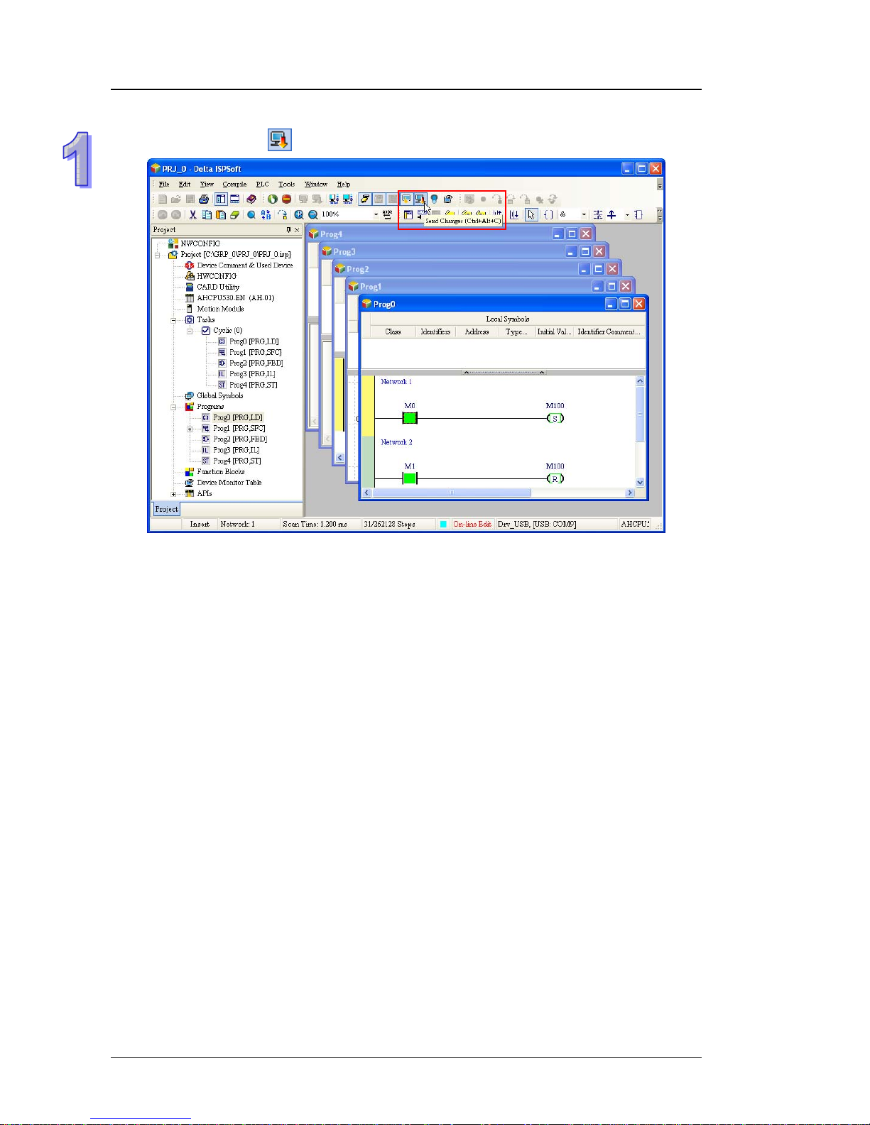
(13) Supporting the on-line debugging mode
z After a single instruction step has been complete, or af
ter a breakpoint is specified, users can
easily find the bug in the program by means of the on-line debugging mode supported by the
AH500 series CPU module.
z If users want to enter the debugging mode, the CPU module must run. Af ter users ena ble the
on-lin
e monitoring function, they have to click
. The debugging screen varies from
programming language to programming language, but the same operation applies to these
programming languages. For the AH500 series PLC, structured texts do not support the
debugging mode, and sequential function charts support the debugging mode during the
action and the transition.
1-11
Page 13
AH500 Hardware Manual
Step 1: Setting the PLC to RUN
Step 2: Entering the on-line mode
1-12
Page 14
Chapter 1 Product Introduction
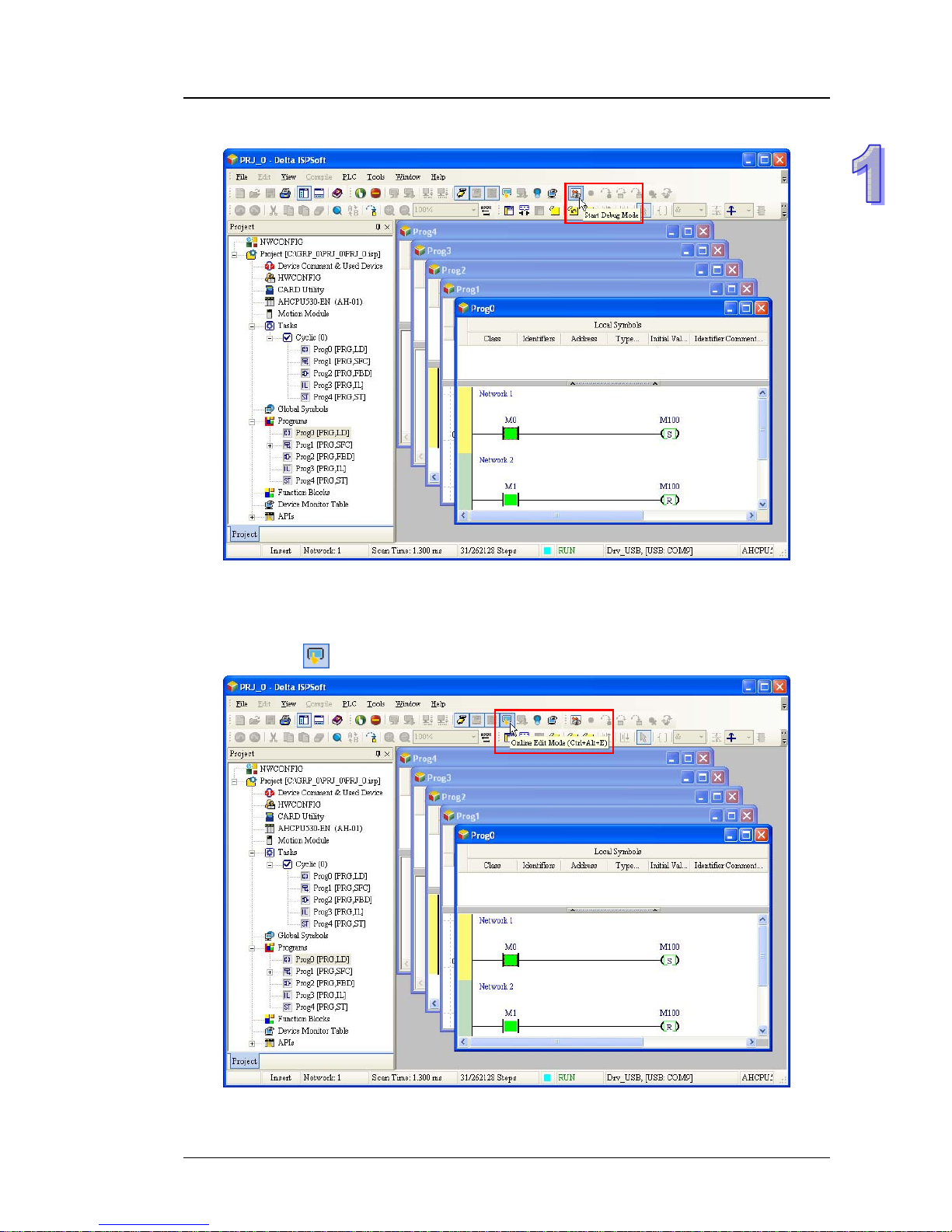
Step 3: Entering the debugging mode
(14) Supporting the on-line editing mode
z When the system runs, users can make use of the on
-line editing mode to update the
program without affecting the operation of the system.
z When the system is in the on-line monitoring m
ode, users can enter the on-line editing mode
by clicking
.
1-13
Page 15
AH500 Hardware Manual
z After the program is modified and compiled, users can update the program in the CPU
module by clicking
.
1-14
Page 16

Chapter 2 Installing the Hardware
Table of Contents
2.1 AH500 Hardware Framework....................................................................2-2
2.1.1 Component Parts of the AH500 Hardware.........................................2-2
2.1.1.1 Necessary Components..............................................................2-2
2.1.1.2 Accessories.................................................................................2-4
2.1.2 Installing Modules on a Main Backplane............................................2-7
2.1.3 Installing Modules on an Extension backplane ...................................2-8
2.1.4 Connecting a Main Backplane to an Extension Backplane ................2-8
2.2 Warning.....................................................................................................2-9
2.3 Installation .................................................................................................2-9
2.3.1 Installation of Modules in a Control Box.............................................2-9
2.3.2 Mounting a Backplane........................................................................2-9
2.3.3 Installing a Module ...........................................................................2-12
2.3.4 Installing a Removable Terminal Block.............................................2-13
2.3.5 Installing a Wiring Module................................................................2-14
2.3.6 Connecting Backplanes....................................................................2-15
2.3.7 Putting a Communication Cable.......................................................2-16
2-1
Page 17
AH500 Hardware Manual
2.1 AH500 Hardware Framework
2.1.1 Component Parts of the AH500 Hardware
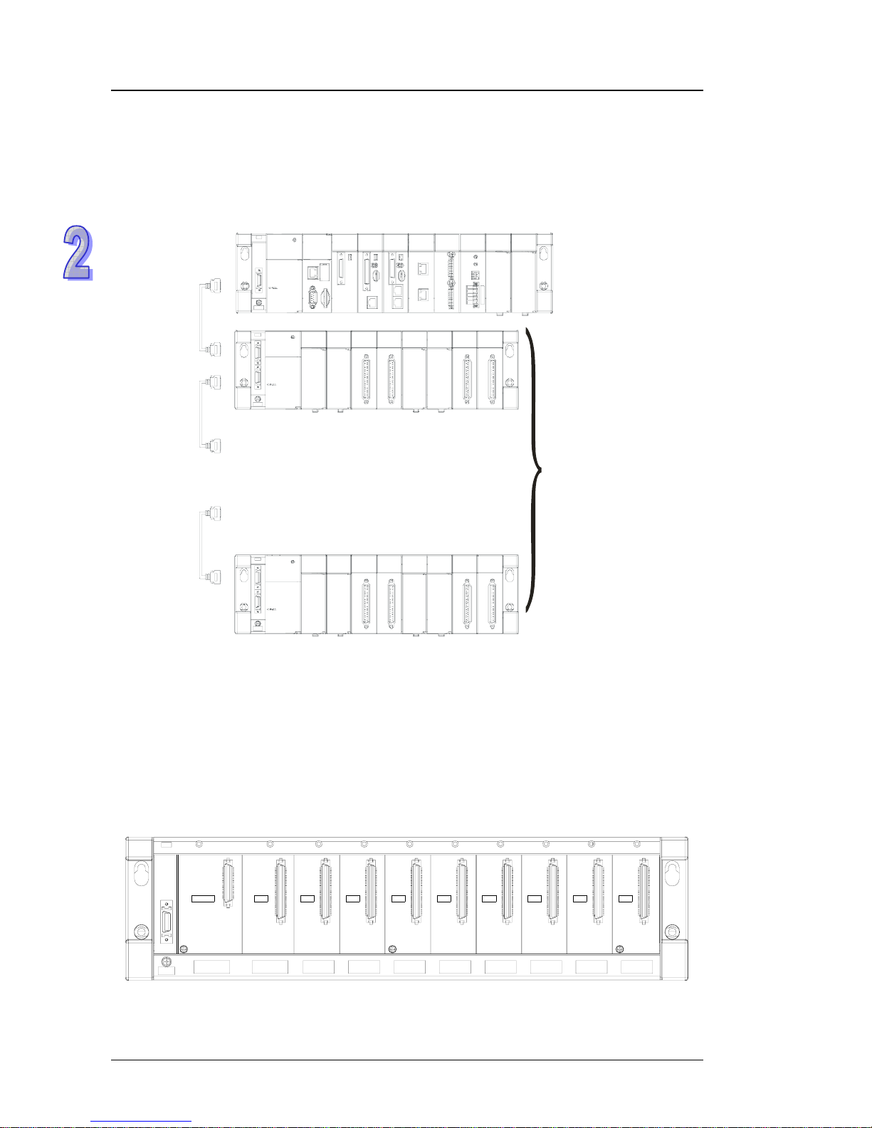
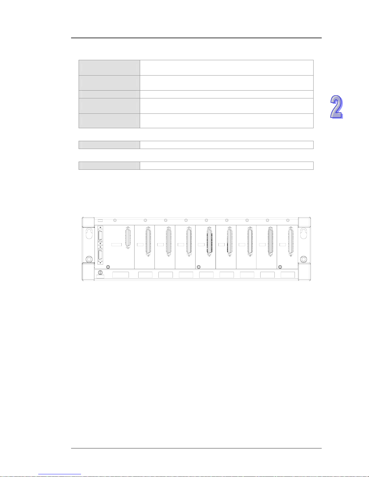
A complete AH500 system consists of a main backplane, extension backplanes, power supply
modules, a CPU module, I/O modules, and extension cables. The basic AH500 system is illustrated
below.
7 backplanes
.
.
.
.
.
.
2.1.1.1 Necessary Components
A complete AH500 system consists of the following four necessary components.
z Main backpla
ne
A CPU module and other modules are installed on a main backplane which provides the function
of conne
cting buses. The main backplanes are divided into four types acco rding to the num b er of
I/O modules installed on the main backplanes. These four types are four-slot main backplanes,
six-slot main backplanes, eight-slot main backplanes, and twelve-slot main backplanes. Besides,
a CPU module installed on a main backplane can be replaced by a RTU module on a control
network. Please notice that there is at least one CPU module on a control network.
POWER CPU I/O0 I/O1 I/O2 I/O3 I/O4 I/O5 I/O6 I/O7
2-2
Page 18
Chapter 2 Installing the Hardware
z Power supply module
A power supply module functions to convert alternating
current to direct current, and provides
power for the modules installed on it. A power supply module has to be installed on the left-most
side of a backplane.
PS05
POWER
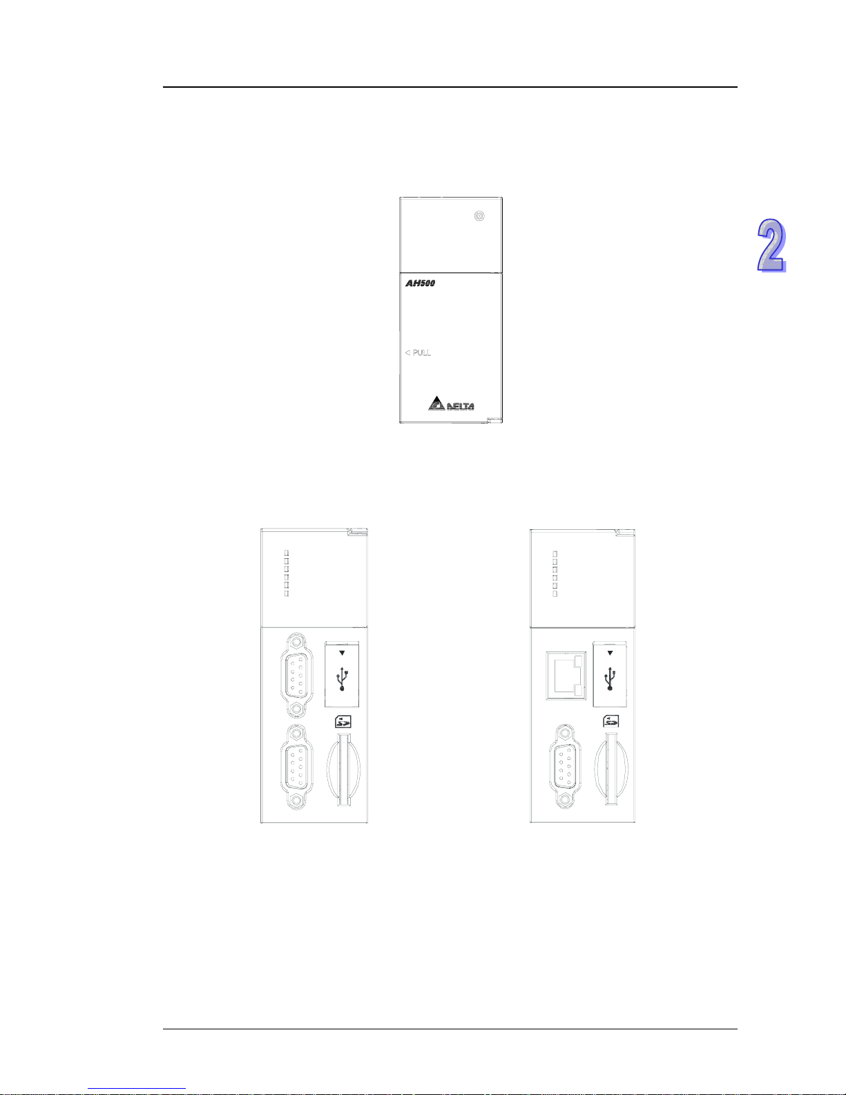
z CPU module
A CPU module is the nucleus of a complete AH500 system. It is responsible for controlling and
managi
ng the whole system, and is installed in the second slot from the left on the main
backplane. Besides, Delta Electronics, Inc. provides businesses with several types of CPU
modules. Users can select a CPU module according to their needs.
CPU530-RS2
RUN
ERROR
BUS FAULT
SYSTEM
COM1
COM2
C
O
M
C
O
M
2
1
USB
CPU530-EN
RUN
ERROR
BUS FAULT
SYSTEM
COM
Ethernet
COM
USB
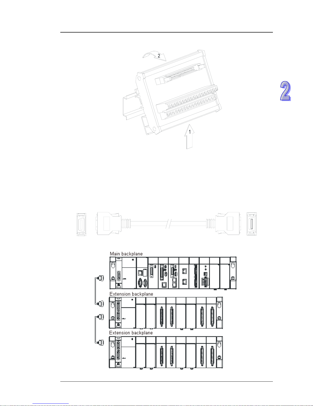
z Communication cable
Several com
munication interfaces are built in a CPU module, and users are provided with many
types of network modul
es. Users can select a suitable Communication cable according to the
actual situation.
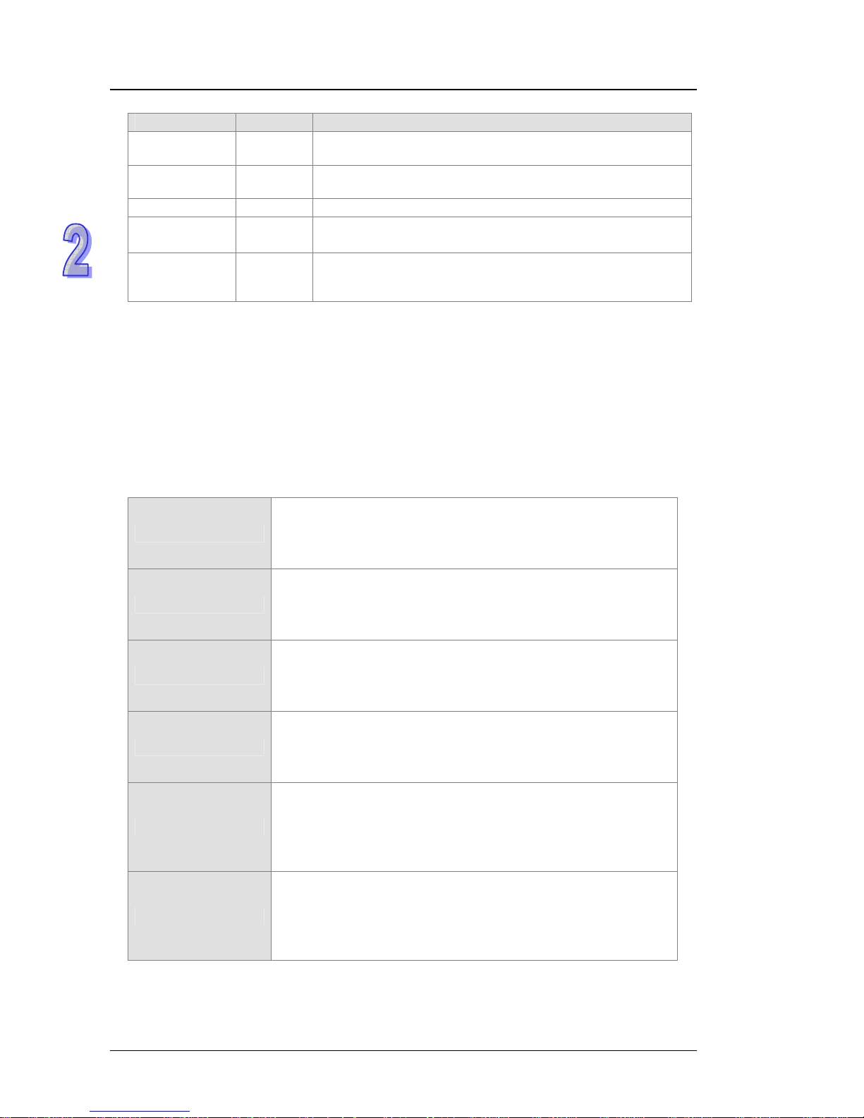
Please refer to the following table for information about the communication interfaces and the
main applic
ations. The specifications for the interface on an extension backplane are defined b y
Delta Electronics, Inc. itself. The interface is used to connect the backplanes, and users need to
use a Delta extension cable.
2-3
Page 19
AH500 Hardware Manual
Interface Connector Application
Communication
port
DB9
Computer/HMI communication/Industrial control network
(RS-232/422/485)
Ethernet RJ45
Computer/HMI communication/Remote control/Data
exchange/Ind
ustrial control network
USB Mini USB Computer communication
DeviceNet DeviceNet
Industrial control network
The maximum data transmission rate is 1 Mbps.
Interface on an
extension
backplane
Delta
co
nnector
Extension cable for a complete AH500 system
2.1.1.2 Accessories
The following are the accessories for an AH500 system. Users can select them according to their
needs.
z Extension module
Ap
art from the standard communication ports on a CPU modul
e, the CPU module does not
equipped with other I/O functions. If users want to use I/O functions, they can select suitable
modules according to the actual situation. The modules which can be used with an AH500
system are listed in the table below.
The digital input/output modules:
AH16AM10N-5A
24 V DC
5 mA
16 inputs
Terminal block
AH32AM10N-5B
24 V DC
5 mA
32 inputs
DB37 connector
AH64AM10N-5C
24 V DC
3.2 mA
64 inputs
Latch connector
AH16AM30N-5A
100~240 V AC
4.5 mA/9 mA (100 V, 50 Hz)
16 inputs
Terminal block
AH16AN01R-5A
240 V AC/24 V DC
2 A
16 outputs
Relay
Terminal block
AH16AN01T-5A
12~24 V DC
0.5 A
16 outputs
Sinking output
Terminal block
2-4
Page 20

Chapter 2 Installing the Hardware
AH16AN01P-5A
12~24 V DC
0.5 A
16 outputs
Sourcing output
Terminal block
AH16AN01S-5A
110/220 V AC
0.5 A
16 outputs
TRIAC
Terminal block
AH32AN02T-5B
12~24 V DC
0.1 A
32 outputs
Sourcing output
DB37 connector
AH32AN02P-5B
12~24 V DC
0.1 A
32 outputs
Sinking output
DB37 connector
AH64AN02T-5C
12~24 V DC
0.1 A
64 outputs
Sinking output
Latch connector
AH64AN02P-5C
12~24 V DC
0.1 A
64 outputs
Sourcing output
Latch connector
AH16AP11R-5A
24 V DC
5 mA
8 inputs
240 V AC/24 V DC
2 A
8 outputs
Relay
Terminal block
AH16AP11T-5A
24 V DC
5 mA
8 inputs
12~24 V DC
0.5 A
8 outputs
Sourcing output
Terminal block
2-5
Page 21

AH500 Hardware Manual
AH16AP11P-5A
24 V DC
5 mA
8 inputs
12~24 V DC
0.5 A
8 outputs
Sinking output
Terminal block
The analog input/output modules:
AH04AD-5A
Four-channel analog input module
16-bit resolution
0~10 V, 0/1~5 V, -5~+5 V, -10~+10 V, 0/4~20 mA, and -20~+20 mA
AH08AD-5B
Eight-channel analog input module
16-bit resolution
0~10 V, 0/1~5 V, -5~+5 V, and -10~+10 V
AH04DA-5A
Four-channel analog output module
16-bit resolution
-10~10 V, and 0/4~20 mA
AH08DA-5B
Eight-channel analog output module
16-bit resolution
-10~+10V, 0~10V, -5~+5V, and 0/1~5V
AH06XA-5A
Four-channel analog input module
16-bit resolution
0~10 V, 0/1~5 V, -5~+5 V, -10~+10 V, 0/4~20 mA, and -20~+20 mA
Two-channel analog output module
16-bit resolution
-10~10 V, and 0/4~20 mA
The temperature measurement modules:
AH04PT-5A
Four-channel four-wire/three-wire RT
D temperature sensor
Sensor type: Pt100, Pt1000, Ni100, Ni1000, and 0~300Ω
AH04TC-5A
Four-channel thermocouple temperature sensor
Sensor type: J, K, R, S, T, E, N, and -150~+150 mV
AH08TC-5A
Eight-channel thermocouple temperature sensor
Sensor type: J, K, R, S, T, E, N, and -150~+150 mV
The network modules:
AH10EN-5A
It is an Ethernet master module with two built-in Ethernet ports, and
support
s a Modbus TCP master.
AH10SCM-5A
It is a serial communication module with two RS-485/RS-422 ports,
and support
s Modbus and the UD link protocol.
There is isolation between two parts of communicatio n, and there
is isolation be
tween two parts of power.
AH10DNET-5A
DeviceNet scanner module
Master
1 Mbps
2-6
Page 22
Chapter 2 Installing the Hardware
The motion control modules:
AH02HC-5A
Two-channel high-sp eed counter modul e
200 kHz
AH04HC-5A
Four-channel high-speed counter module
200 kHz
AH05PM-5A
Two-axis pulse train motion control m odule (1 MHz)
AH10PM-5A
Six-axis pulse train motion control module
(Four axes: 1 MHz; Two axes: 200 kHz)
AH20MC-5A
Twelve-axis DMCNET (Delta Motion Control Network) motion
control modu
le (10 Mbps)
The RTU module:
AHRTU-DNET-5A
RTU module for DeviceNet
The space module:
AHASP01-5A
Space module used for an empty I/O slot
z Extension backplane
If the number of slots on the main backplane is not suff icient for the whole system, users can use
the extension
backplanes to increase the number of extension modules. The extension
backplanes are divided into two types according to the number of extension modules installed on
the extension backplanes. These two types are six-slot extension backplanes, and eight-slot
extension backplanes.
POWER I/O0 I/O1 I/O2 I/O3 I/O4 I/O5 I/O6 I/O7
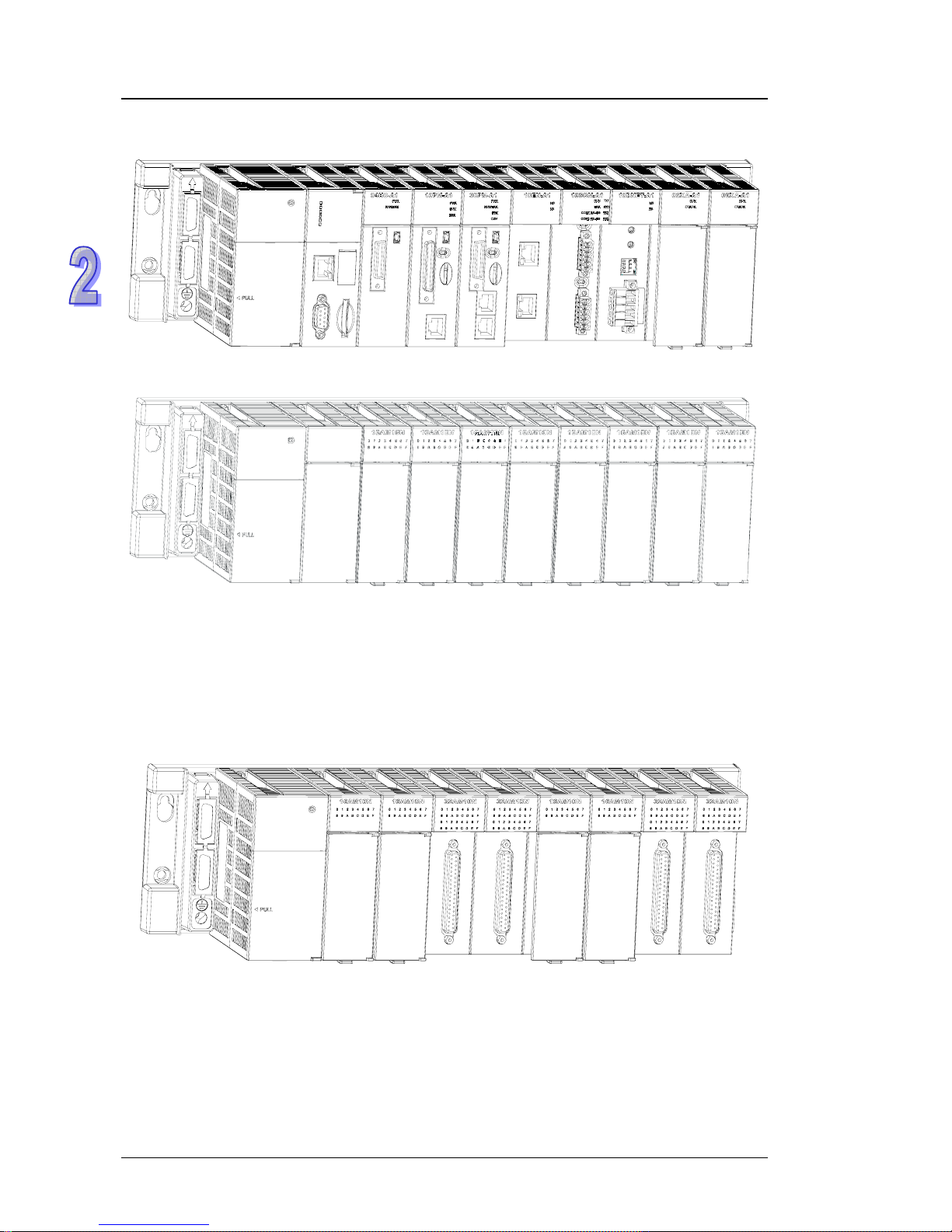
2.1.2 Installing Modules on a Main Backplane
For a main backplane as a master, the first slot from the left is for a power supply module, the
second slot is for a CPU module, and the slots following the second slot are for extension modules.
All AH500 series extension modules can be installed on a main backplane. Eight AH500 series
network modules at most can be installed on a main backplane, but no limits are imposed on the
number of other modules which can be installed on a main backplane. No limits are imposed on the
installing of modules except that a power supply module and a CPU module have to be installe d in
the first slot and the second slot respectively. Therefore, users can configure the hardware by
themselves. Besides, twelve extension modules at most can be installed on a main backpla ne.
For a main backplane as a RTU, the second slot is for a RT
U module, and only digital input/output
modules, analog input/output modules, temperature measurement modules and AH10SCM-5A are
supported.
2-7
Page 23
AH500 Hardware Manual
z Main backplane as a master
z Main backplane as a RTU
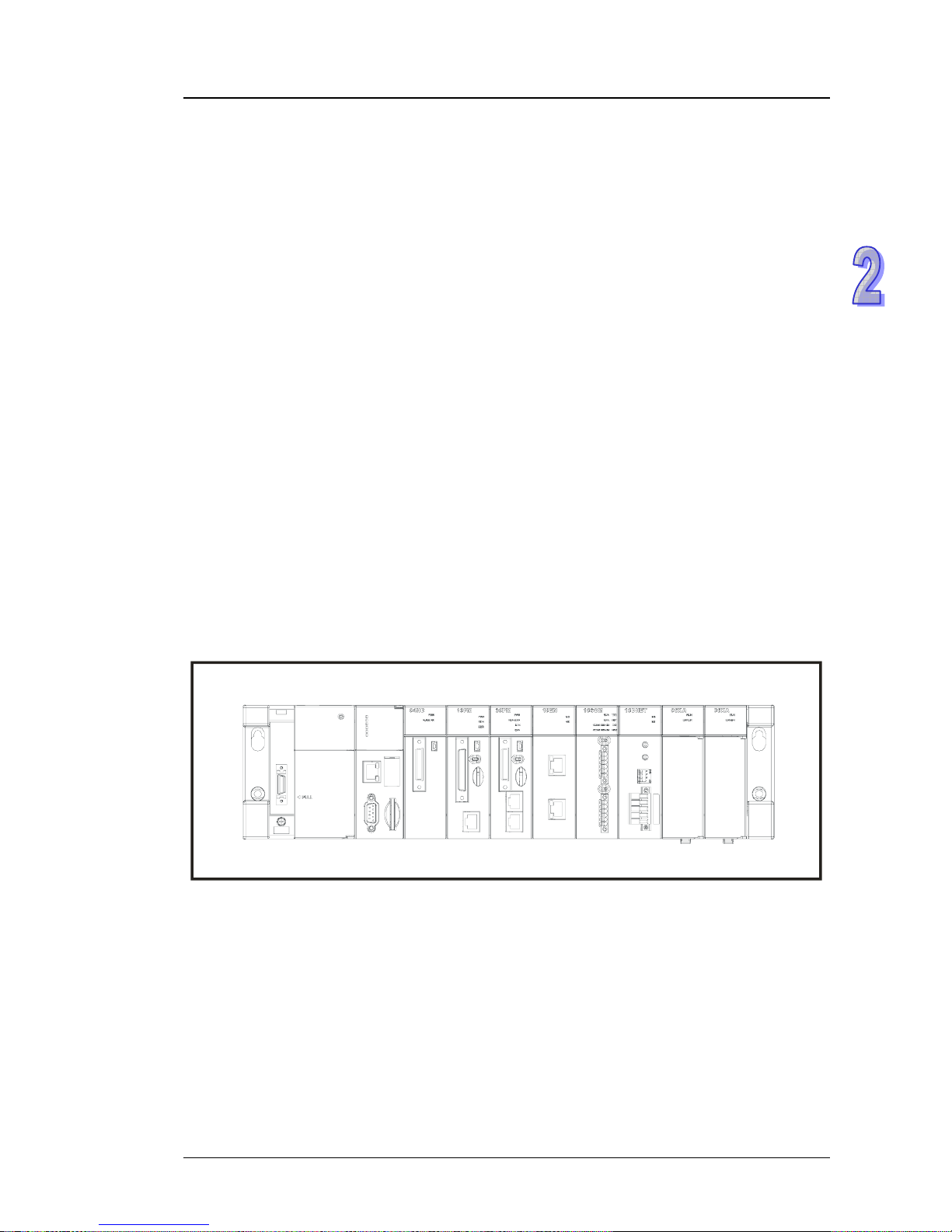
2.1.3 Installing Modules on an Extension backplane
For an extension backplane, the first slot from the left is for a power supply module, and the sl ots
following the first slot are for extension modules. Only digital input/output modules, analog
input/output modules, temperature measurement modules, and AH10SCM-5A can be installed on
an extension backplane. Besides, users do not need to arrange the extension modules in a specific
order.
z Extension backplan
e
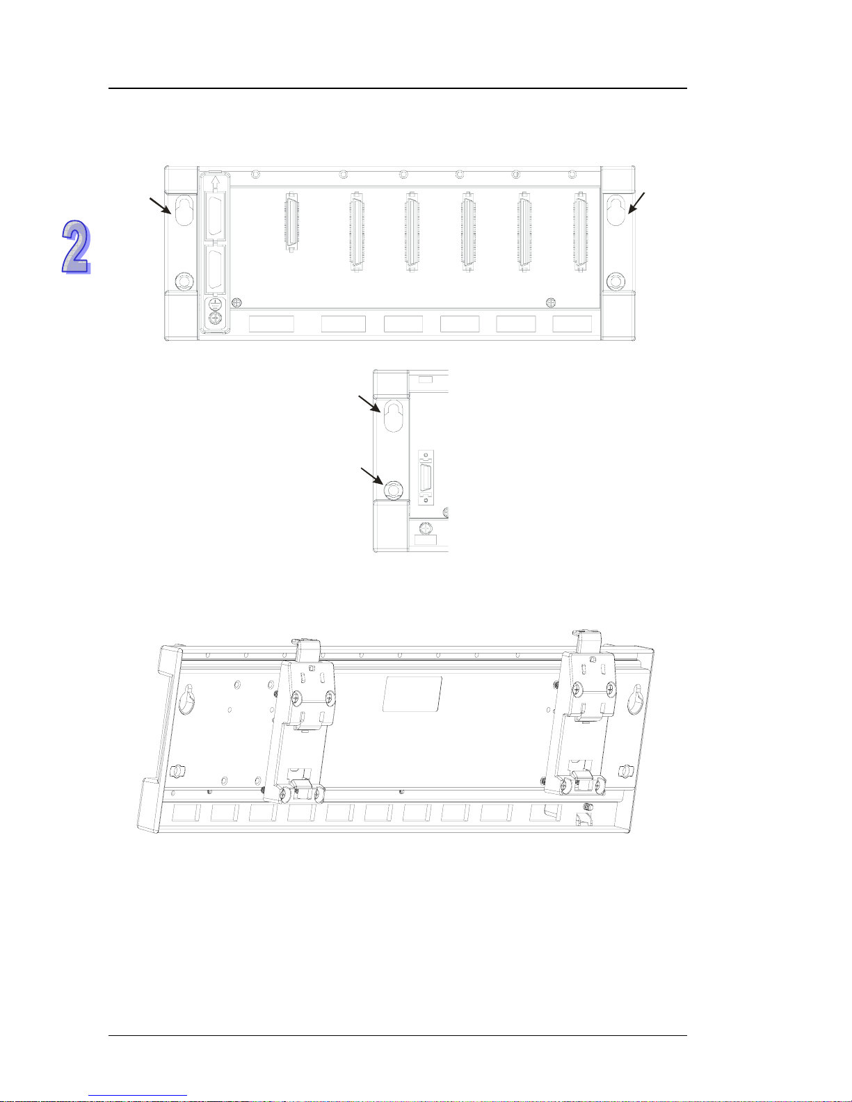
2.1.4 Connecting a Main Backplane to an Extension Backplane
A main backplane can be connected to an extension b ackplane through the interface on the lef t side
of the main backplane, the interface on the left side of the extension backplane, and a Delta
extension cable. For a CPU module or a RTU, a main backpl ane can be connected to seven
extension backplanes at most through the interfaces on the backplanes. Therefore, if there is a CPU
module and there are several RTUs, not only the CPU module can be connected to seven extension
backplanes, but also every RTU can connect to seven extension backplanes.
2-8
Page 24
Chapter 2 Installing the Hardware
There are two ports on an extension backplane. The upper port is used to connect to a superior
backplane, and the lower port is used to connect to an inferior backplane.
2.2 Warning
z An AH500 system only supports the horizontal installation, and a power supply module has to be
installed on the left-most side of a backplane.
z Before a module is installed, please make sure of the size of the module and that of a backplane.
To prevent the misestimate from resulting in insufficient installation space, the size of the
connector of a communication cable, and the room which needs to be reserve d have to be taken
into account.
z Please make sure that the work environment conforms
to the specifications for the products. It is
necessary to take account of the basic temperature/humidity control and the dust/corrosion
prevention.
z The electromagnetic interference will result in the wrong a
ction of the whole system. Therefore,
users have to do EMC design carefully. Please refer to chapter seven in this manual for more
information related to EMC standards.
z If the specifications for the components such as scre
ws and washers are noted specifically in the
manual, please use the components conforming to the specifications.
z If a cable is connected to a communication port, please make
sure that the connector of the cable
is joined to the port on the module properly.
z A backplane has to be mounted on a plane stably instead of being just set on the plane. After it is
inst
alled, please make sure that it is fixed on the plane.
2.3 Installation
2.3.1 Installation of Modules in a Control Box
z A PLC has to be installed in a closed control box. In order to ensure that the PLC radiates heat
normally, the space between the PLC and the control box has to be larger than 50 millimeters.
50mm>
50mm>
50mm>
50mm>
Please keep the PLC away from high-voltage equipment, high-voltage wires, and high-voltage
motors
.
In order to prevent the temperature of a PLC from ri
sing, please do not install the PLC
vertically on the bottom/top in the control box.
Please install a PLC horizontally in the control box, as sho
wn above.
If users intend to increase the number of modules, they have to leave some space for installing
the module
s in the control box.
2.3.2 Mounting a Backplane
z Fixing a backplane by screws
Please mount a backplane on a plane by means of M5 screws, as illustrated below. To fix the
backplane, u
sers need to judge the length of a screw, the size of a thread, and whether to use a
2-9
Page 25
AH500 Hardware Manual
nut according to the actual condition of the plane unless there are specific specifications for a
screw which are indicated in the pictures below.
1. Tighten the M5 screws in the holes indicated by a.
a
a
2. Tighten the two screws in the holes indicated by b.
b
a
z Installing a DIN Rail
1.
The installation is applicable to a 35 millimeter DIN rail.
2. Install the mounting clips on a backplane.
3. Install the backplane on a DIN rail.
Step 1: Pull the clasp in the direction indicated by the arrow.
Step 2: Hang the backplan e on a DIN rail.
Step 3: Press the clasp.
2-10
Page 26
Chapter 2 Installing the Hardware
DIN rail
1
2
3
z Removing a DIN rail
Step 1: Press the clasp in the direction i
ndicated by the arrow.
Step 2: Remove the backplane.
DIN rail
1
2
2-11
Page 27
AH500 Hardware Manual
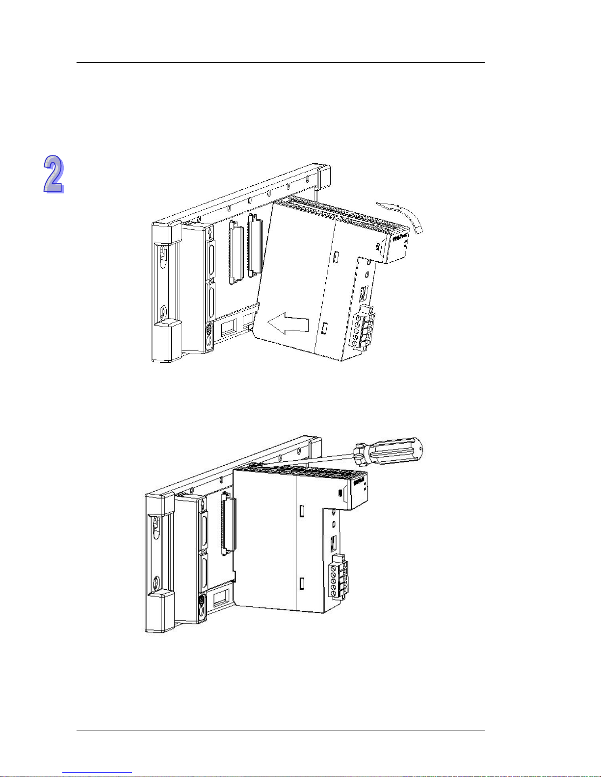
2.3.3 Installing a Module
Insert a module into a slot, make sure that the module is installed on the backplane properly, and
tighen the the screw, as illustrated below.
1. Insert the projection under the module into the hole in the ba
ckplane.
2. Push the module in the direction indicated by the arrow until it clicks.
3. Tighten the screw on the module.
2-12
Page 28
Chapter 2 Installing the Hardware
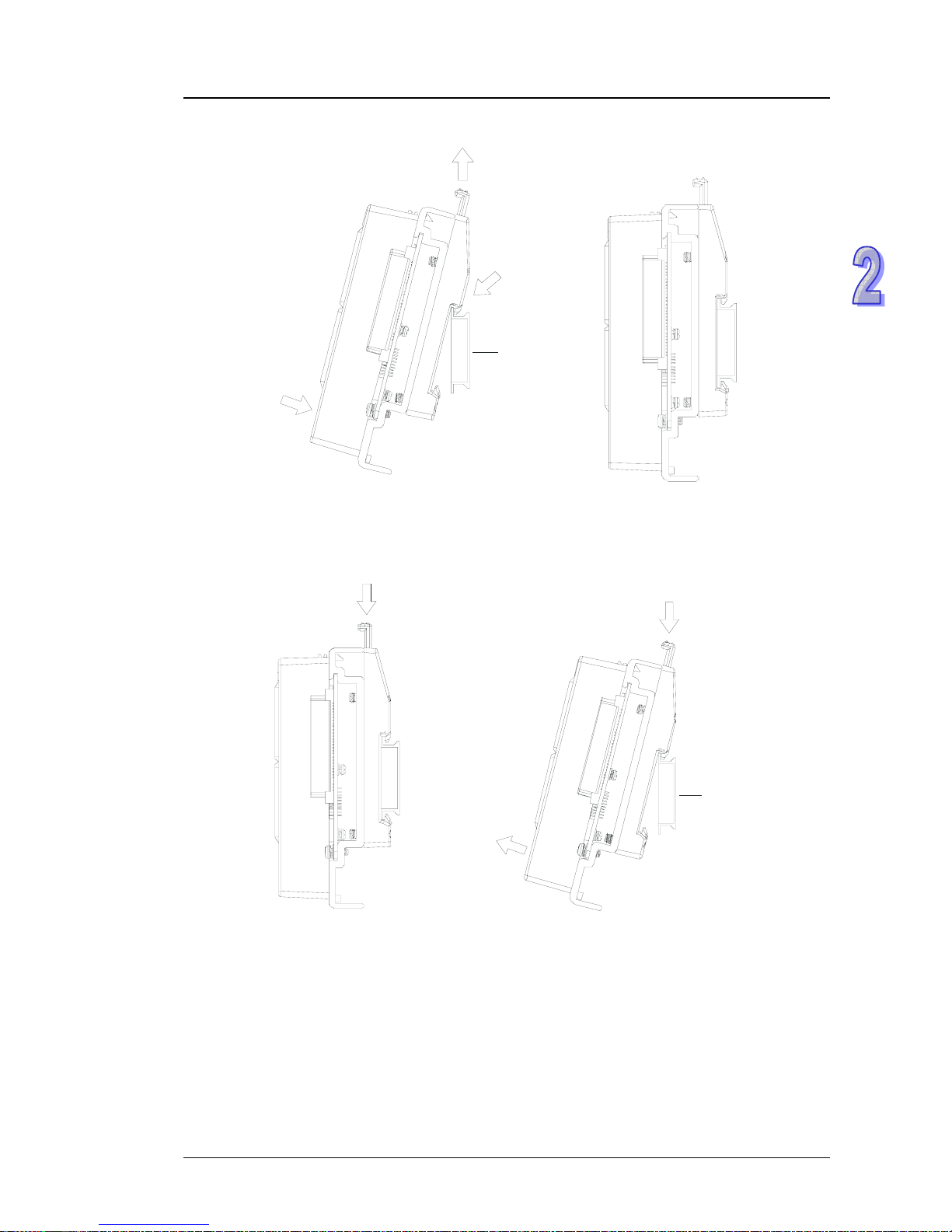
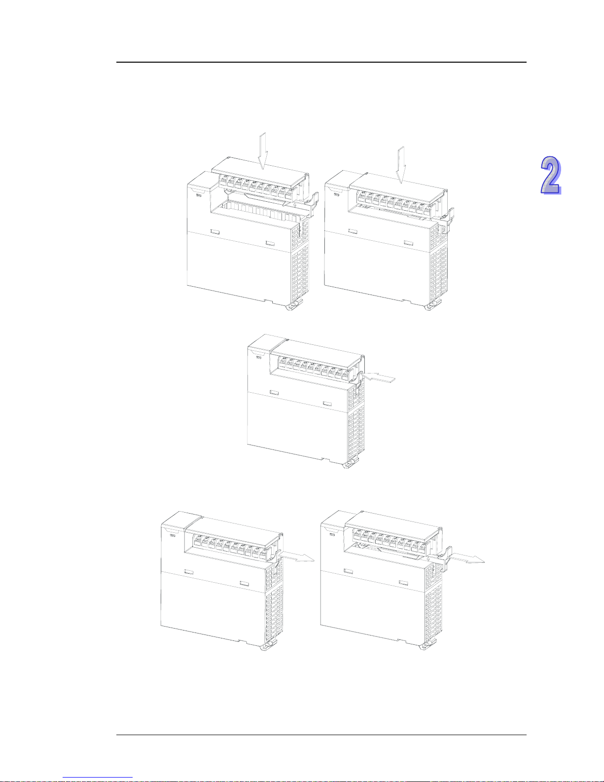
2.3.4 Installing a Removable Terminal Block
z Installation
1. Level a terminal block at the printed circuit board, and press it into the module.
2. Press the clip in the direction indicated by the arrow.
z Rem
oval
1.
Pull the clip in the direction indicated by the arrow.
2-13
Page 29
AH500 Hardware Manual
2. Pull up the clip.
3. The terminal block is removed.
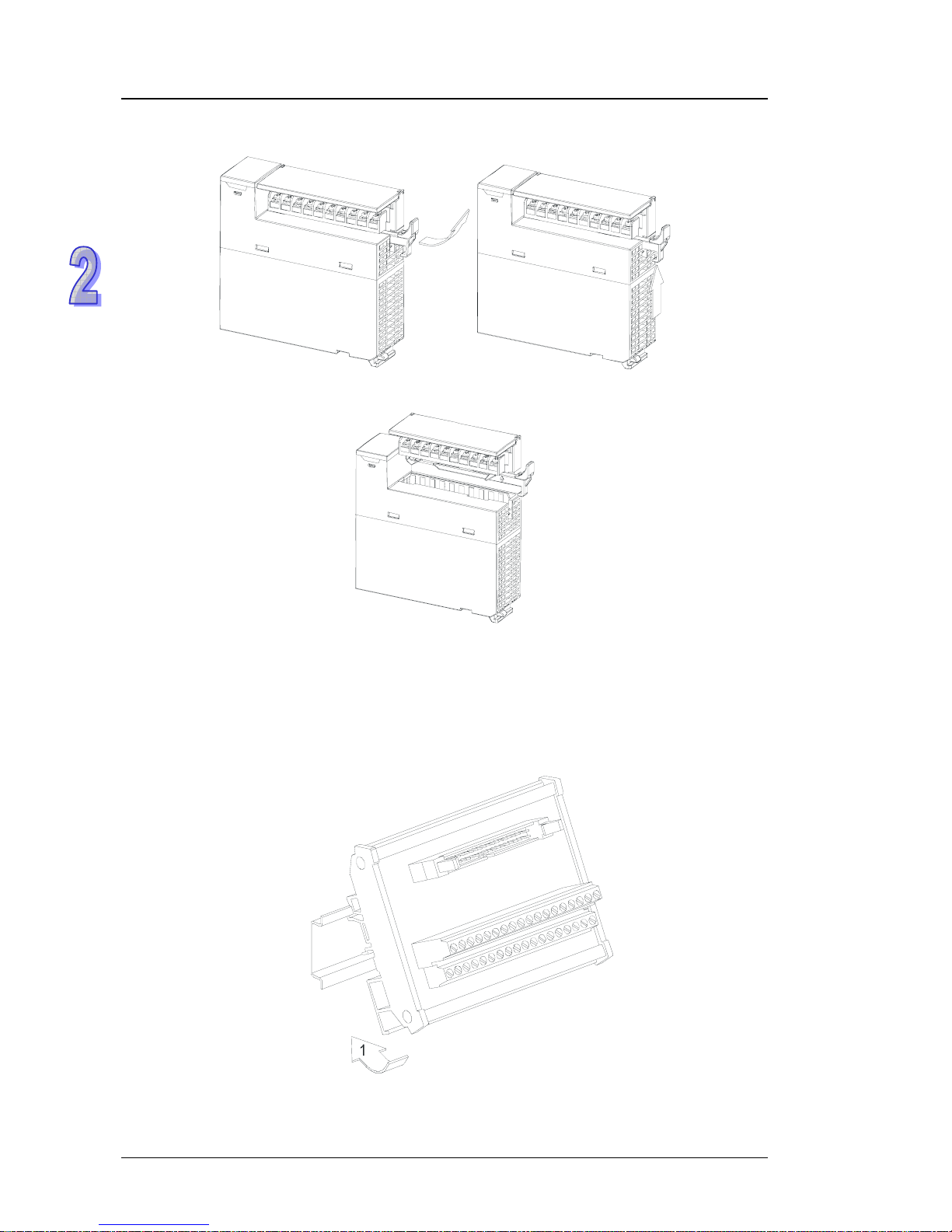
2.3.5 Installing a Wiring Module
z Installation
1. One side of a wiring module has to be fixed first.
2. Press the driver board in the direction indicated by arrow 1, and ma
ke sure that the groove is
combined with the DIN rail.
z Removal
1.
Push the wiring module in the direction i
ndicated by arrow 1.
2-14
Page 30
Chapter 2 Installing the Hardware
2. Pull the wiring module in the direction indicated by arrow 2.
2.3.6 Connecting Backplanes
Connect the backplanes through the extension cables, and make sure that the connectors of the
cables are joined to the ports properly, as illustrated below.
z Extension ca
ble
1. AHACAB06-5 A (0.6 m)
2. AHACAB10-5 A (1.0 m)
3. AHACAB15-5 A (1.5 m)
4. AHACAB30-5 A (3.0 m)
10
1
11
20
10
1
11
20
Note: The extension cable longer than 3 meters can be cu stomized.
z Connecting the backplanes
2-15
Page 31
AH500 Hardware Manual
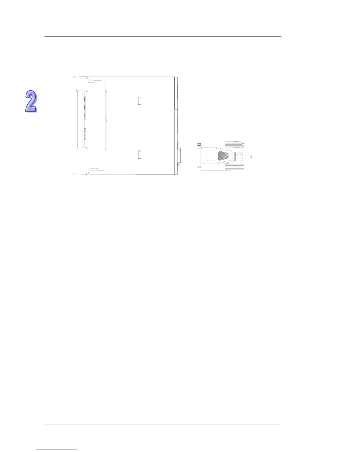
2.3.7 Putting a Communication Cable
Put a communication cable in the port on a CPU module, and make sure that the connector of the
cable is joined to the port properly,
2-16
Page 32

Chapter 3 Product Specifications
Table of Contents
3.1 General Specifications...............................................................................3-3
3.2 Specifications for CPU Modules................................................................3-3
3.2.1 General Specifications .......................................................................3-3
3.2.2 Profiles...............................................................................................3-5
3.2.3 Dimensions ........................................................................................3-7
3.3 Specifications for Backplanes....................................................................3-7
3.3.1 General Specifications........................................................................3-7
3.3.2 Profiles...............................................................................................3-8
3.3.3 Dimensions ......................................................................................3-10
3.4 Specifications for the Power Supply Module............................................3-12
3.4.1 General Specifications......................................................................3-12
3.4.2 Profile...............................................................................................3-12
3.4.3 Dimensions ......................................................................................3-13
3.4.4 Arrangement of Terminals ................................................................3-13
3.5 Specifications for Digital Input/Output Modules.......................................3-14
3.5.1 General Specifications......................................................................3-14
3.5.2 Profiles.............................................................................................3-16
3.5.3 Dimensions ......................................................................................3-22
3.5.4 Arrangement of Input/Output Terminals............................................3-27
3.6 Specifications for Analog Input/Output Modules......................................3-32
3.6.1 General Specifications......................................................................3-32
3.6.2 Profiles.............................................................................................3-36
3.6.3 Dimensions ......................................................................................3-37
3.6.4 Arrangement of Input/Output Terminals............................................3-38
3.7 Specifications for Temperature Measurement Modules...........................3-39
3.7.1 General Specifications......................................................................3-39
3.7.2 Profiles.............................................................................................3-40
3.7.3 Dimensions ......................................................................................3-41
3.7.4 Arrangement of Input/Output Terminals............................................3-41
3.8 Specifications for Network Modules.........................................................3-42
3.8.1 General Specifications......................................................................3-42
3.8.2 Profiles.............................................................................................3-43
3.8.3 Dimensions ......................................................................................3-47
3.8.4 Arrangement of Input/Output Terminals............................................3-48
3.9 Specifications for Motion Control Modules...............................................3-49
3.9.1 General Specifications......................................................................3-49
3.9.2 Profiles.............................................................................................3-59
3.9.3 Dimensions ......................................................................................3-65
3.9.4 Arrangement of Input/Output Terminals............................................3-68
3.10 Specifications for the RTU module.......................................................3-70
3.10.1 General Specifications..................................................................3-70
3.10.2 Profiles..........................................................................................3-71
3.10.3 Dimensions...................................................................................3-72
3.11 Space Module and Extension Cables ..................................................3-73
3-1
Page 33

3-2
3.11.1 Profiles .........................................................................................3-73
3.11.2 Dimensions...................................................................................3-74
Page 34

AH500 Hardware Manual
3.1 General Specifications
Item Specifications
Operating
temperature
-20~60°C
Storage temperature
-40~85°C
Operating humidity
50~95%
No condensation
Storage humidity
5~95%
No condensation
Vibration/Shock
resistance
International standards IEC 61131-2, IEC 68-2-6 (TEST Fc)/
IEC 61 131-2 & IEC 68-2-27 (TEST Ea)
Work environment
No corrosive gas exists.
Installation location
In a control box
Pollution degree
2
3.2 Specifications for CPU Modules
3.2.1 General Specifications
Item
AHCPU500/510/
520/530-RS2
AHCPU500/510/
520/530-EN
Remark
Execution
The program is executed cyclically.
Input/Output control
Regenerated inputs/outputs
Direct inputs/outputs
The inputs and outputs can
be controlled through the
direct inputs and direct
outputs.
IEC 61 131-3
programming language
Ladder diagrams, function block
diagrams, instruction lists,
structured texts, and sequential
function charts
Instruction execution
speed
0.3 ms/ksteps
Number of instructions
Approximately 666 instructions
Constant scan cycle (ms)
1-32000
(The scan cycle can be increased
by one millisecond.)
Setting the parameter
Program capacity (step)
16 ksteps (AHCPU500)
64 ksteps (AHCPU510)
128 ksteps (AHCPU520)
256 ksteps (AHCPU530)
Installation
DIN rails or screws
Installation of a module
A module is installed directly on a
backplane.
Connection between two
backplanes
An extension cable connects two
backplanes.
3-3
Page 35

Chapter 3 Product Specifications
3-4
Item
AHCPU500/510/
520/530-RS2
AHCPU500/510/
520/530-EN
Remark
Number of modules
Twelve input/output modules at
most can be installed on a main
backplane. Eight input/output
modules at most can be installed
on an extension backplane. Seven
extension backplanes at most can
be connected. Sixty-eight
input/output modules at most can
be installed.
Number of backplanes
Eight backplanes at most (one
main backplane and seven
extension backplanes)
Number of tasks
283 tasks (Cyclic: 32; I/O
interrupt: 32; timed interrupt: 4;
communication interrupt: 2;
external 24 V low-voltage
interrupt: 1; External interrupt:
212)
Number of input/output
devices
8192 input/output devices
(X0.0~X511.15/Y0.0~Y511.15)
Number of devices which can
be used in a program
Number of inputs/outputs
768 inputs/outputs (AHCPU500)
1280 inputs/outputs (AHCPU510)
2304 inputs/outputs (AHCPU520)
4352 inputs/outputs (AHCPU530)
Number of inputs/outputs
accessible to an actual
input/output module
Input relay [X]
8192 (X0.0~X511.15)
Output relay [Y]
8192 (Y0.0~Y511.15)
Internal relay [M]
8192 (M0~M8191)
Link register [L]
AHCPU500: 16384
(L0.0~L16383.15)
AHCPU510: 32768
(L0.0~L32767.15)
AHCPU520: 65536
(L0.0~L65535.15)
AHCPU 530: 65536
(L0.0~L65535.15)
Timer [T]
2048 (T0~T2047)
Counter [C]
2048 (C0~C2047)
32-bit counter [HC]
64 (HC0~HC63)
Data register [D]
AHCPU500:16384 (D0~D16383)
AHCPU510: 32768 (D0~D32767)
AHCPU520: 65536 (D0~D65535)
AHCPU530: 65536 (D0~D65535)
Stepping relay [S]
2048 (S0~S2047)
Index register [E]
32 (E0~E31)
Special auxiliary relay [SM]
2048 (SM0~SM2047)
Special data register [SR]
2048 (SR0~SR2047)
Serial communication port
Two
RS-232/RS-485/
RS-422
communication
ports
One
RS-232/RS-485/
RS-422
communication
port
Ethernet port
- 10/100 M
USB port
Mini USB
Page 36

AH500 Hardware Manual
3-5
Item
AHCPU500/510/
520/530-RS2
AHCPU500/510/
520/530-EN
Remark
Storage interface
SD Card (SD 1.0)
Remote RUN/STOP
The setting range is X0.0~X511.15.
Real-time clock
Years, months, days, hours,
minutes, seconds, and weeks
3.2.2 Profiles
AHCPU500-RS2/AHCPU510-RS2/AHCPU520-RS2/AHCPU530-RS2
CPU530-R S2
RUN
ERROR
BUS FAULT
SYSTEM
COM1
COM2
C
O
M
C
O
M
2
1
USB
C
O
M
C
O
M
2
1
1
12
2
3
4
6
7
13
6
8
9
11
10
14
15
AHCPU500-EN/AHCPU510-EN/AHCPU520-EN/AHCPU530-EN
CPU530-EN
RUN
ERROR
BUS F AULT
SYSTEM
COM
Ethernet
COM
USB
Ethernet
COM
2
13
4
5
6
7
8
9
11
10
14
15
1
12
6
Number Name Description
1 Model name Model name of the CPU module
RUN LED
indicator
Operating status of the CPU module
ON: The user program is being executed.
OFF: The execution of the user program stops.
Blink: The user program is in a debugging mode.
ERROR LED
indicator
Error status of the CPU module
ON: A serious error occurs in the system.
OFF: The system is normal.
Blink: A slight error occurs in the system.
2
BUS FAULT LED
indicator
Error status of the I/O bus
ON: A serious error occurs in the I/O bus.
OFF: The I/O bus is normal.
Blink: A slight error occurs in the I/O bus.
Page 37

Chapter 3 Product Specifications
3-6
Number Name Description
SYSTEM LED
indicator
System status of the CPU module
ON: The external input/output is forced ON/OFF.
OFF: The system is in a default status.
Blink: The CPU module is being reset./The value in the device is
being cleared.
2
COM LED
indicator
COM1 LED
indicator
COM2 LED
indicator
Communication status of the communication port
OFF: There is no communication through the communication
port.
Blink: There is communication through the communication port.
3 COM2 Providing the RS-232/RS-485/RS-422 communication interface
4 COM1/COM Providing the RS-232/RS-485/RS-422 communication interface
5 Ethernet port Providing the Ethernet communication interface
6 USB port Providing the mini USB communication interface
7 SD slot Providing the SD interface
Function which the system executes
SW1
OFF: No action (default)
ON: Write protection
SW2
OFF: No action (default)
ON: The system is copied when the CPU module is
supplied with powered. (The user program, the CPU
paramter, the module table, and the setting values in
the devices are copied from the memory card to the
CPU module.)
SW3
OFF: No action (default)
ON: It is used with the CLR button to backup the system.
(The user program, the CPU paramter, the module
table, and the setting values in the devices are
backupped from the memory card to the CPU
module.)
8 DIP switch
SW4
It is used with SW3.
OFF: When the system is backupped, the values in the
devices are backupped.
ON: When the system is backupped, the values in the
devices are not backupped.
9 RST button
Resetting the CPU module, and restoring it to the default factory
value
10 CLR button Clearing the value in the latched device
11
RUN/STOP
switch
RUN: The user program is executed.
STOP: The execution of the user program stops.
12 Label Nameplate
13 Set screw Fixing the module
14 Connector Connecting the module and a backplane.
15 Projection Fixing the module
Page 38

AH500 Hardware Manual
3.2.3 Dimensions
AHCPU500-RS2/AHCPU510-RS2/AHCPU520-RS2/AHCPU530-RS2
CPU530-R S2
RUN
ERROR
BUS FAULT
SYSTEM
COM1
COM2
C
O
M
C
O
M
2
1
USB
C
O
M
C
O
M
2
1
40 103
110
3.6
6
Unit: mm
AH
CPU500
-EN/AHCPU510-EN/AHCPU520-EN/AHCPU530-EN
CPU530-EN
RUN
ERROR
BUS F AULT
SYSTEM
COM
Ethernet
COM
USB
Ethernet
COM
40 103
3.6
6
110
Unit: mm
3.3 Specifications for Backplanes
3.3.1 General Specifications
The specifications for main backplanes
Model
Item
AHBP04M1-5A AHBP06M1-5A AHBP08M1-5A AHBP12M1-5A
Number of slots
4 6 8 12
Applicable power
supply module
AHPS05-5A
Applicable
input/output module
The AH500 series input/output modules can be installed.
3-7
Page 39

Chapter 3 Product Specifications
The specifications for extension backplanes
Model
Item
AHBP06E1-5A AHBP08E1-5A
Number of slots
6 8
Applicable power
supply module
AHPS05-5A
Applicable
input/output module
Digital input/output modules, analog input/output modules,
temperature measurement module, and AH10SCM-5A
3.3.2 Profiles
The profile of the main backplane AHBP08M1-5A
1
1
2
3 4 5 6
7
9
10
8
8
Number Name Description
1 Mounting hole Fixing the backplane
2 Extension port It is connected to an inferior backplane.
3 Mounting hole After a module is installed, it is fixed by a screw.
4 Connector Connecting the backplane and a power supply module
5 Connector Connecting the backplane and a CPU module
6 Connector Connecting the backplane and an input/output module
7 Hole The projection under a module is inserted into this hole.
8 Mounting clip Hanging a backplane on a DIN rail
9 Mounting hole After a mounting clip is installed, it is fixed by screws.
10 Locating hole A mounting clip is pressed into these locating holes.
3-8
Page 40

AH500 Hardware Manual
The profile of the extension backplane AHBP08E1-5A
1
2
4 5 6
7
8
1
9
10
8
8
Number Name Description
1 Mounting hole Fixing the backplane
2 Extension port 1 It is connected to a superior backplane.
3 Extension port 2 It is connected to an inferior backplane.
4 Connector Connecting the backplane and a power supply module
5 Connector Connecting the backplane and an input/output module
6 Mounting hole After a module is installed, it is fixed by a screw.
7 Hole The projection under a module is inserted into this hole.
8 Mounting clip Hanging a backplane on a DIN rail
9 Mounting hole After a mounting clip is installed, it is fixed by screws.
10 Locating hole A mounting clip is pressed into these locating holes.
3-9
Page 41

Chapter 3 Product Specifications
3.3.3 Dimensions
The main backplane AHBP04M1-5A
110
49.5
23.6
37.7
16.7
298
272.49
Unit: mm
The main backplane AHBP06M
1-5A
110
49.5
23.6
37.7
16.7
369
343.5
Unit: mm
The main backplane AHBP08M1-5A
110
49.5
23.6
414.5
440
16.7
37.7
Unit: mm
3-10
Page 42

AH500 Hardware Manual
The main backplane AHBP12M1-5A
110
556.5
582
49.5
23.6
16.7
37.7
Unit: mm
The ex
tensio
n backplan
e AHBP06E1-5A
110
49.5
23.6
16.7
37.7
348
303
Unit: mm
The extension backplane AHBP08E1-5A
110
49.5
23.6
16.7
37.7
399
374
Unit: mm
3-11
Page 43

Chapter 3 Product Specifications
3.4 Specifications for the Power Supply Module
3.4.1 General Specifications
AHPS05-5A
Item Specifications
Supply voltage
100~240 V AC (-15%~10% )
50/60 Hz5%
Action
specifications
If the input power supply is larger than 85 V AC, the power supply
module can function normally.
Allowable
instantaneous
power failure
time
If the instantaneous power failure time is within ten milliseconds, the
power supply module keeps running.
Fuse
4 A/250 V AC
Inrush current
45 A within 1 millisecond at 115 V AC
24 V DC output
The maximum current is 2.5 A.
It is only for a backplane.
Power
protection
The 24 V DC output is equipped with the short circuit protection and the
overcurrent protection.
Surge voltage
withstand level
1,500 V AC (Primary-secondary), 1,500 V AC (Primary-PE), 500 V AC
(Secondary-PE)
Insulation
voltage
Above 5 MΩ
(The voltage between all inputs/outputs and the ground is 500 V DC.)
Ground
The diameter of the ground should not be less than the diameters of the
cables connected to the terminals L and N.
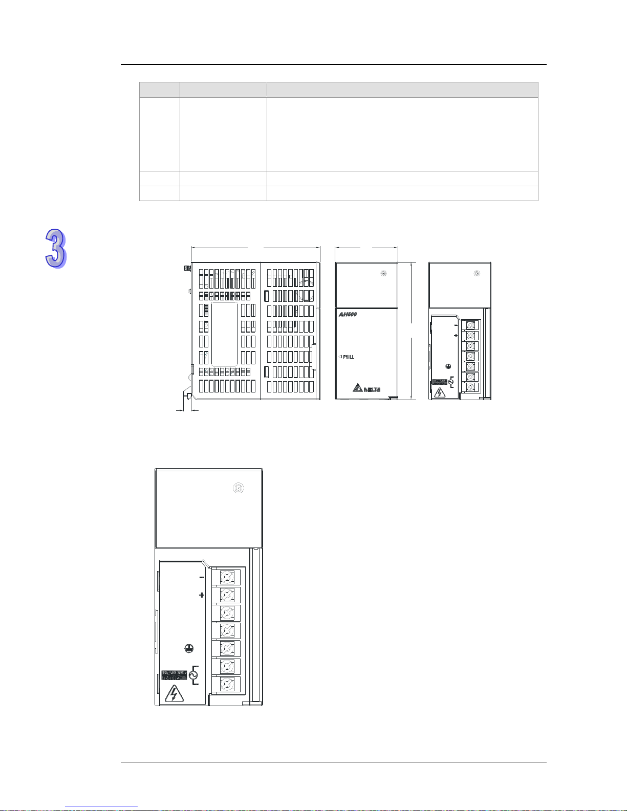
3.4.2 Profile
AHPS05-5A
PS05
POWER
PS05
POWER
NC
FG
INPUT
VS
VS
LG
N
L
1
2
4
3
5
Number Name Description
1 Model name Model name of the power supply module
2
POWER LED
indicator (green)
Indicating the status of the power supply
3-12
Page 44
AH500 Hardware Manual
3-13
Number Name Description
3
Arrangement of
the terminals
VS-: It is connected to the negative 24 V DC power supply.
VS+: It is connected to the positive 24 V DC power supply.
NC: No connection
FG: Functional ground
LG: Line ground
L/N: AC power input
4 Terminal Terminal for wiring
5 Label Nameplate
3.4.3 Dimensions
AHPS05-5A
PS05
POWER
PS05
POWER
NC
FG
INPUT
VS
VS
LG
N
L
10
3
110
50
6
Unit: mm
3.4.4 Arrangement of Terminals
AHPS05-5A
PS05
POWER
NC
FG
INPUT
VS
VS
LG
N
L
VS-: It is connected to the negative 24 V DC power
supply, and used to detect the external power
supply.
VS+: It is connected to the positive 24 V DC power
supply, and used to detect the external power
supply.
NC: No connection
FG: Functional ground
LG: Line ground
L/N: AC power input
Page 45

Chapter 3 Product Specifications
3.5 Specifications for Digital Input/Output Modules
3.5.1 General Specifications
The inputs through which 24 V DC signals pass
Model
Item
AH16AM10N AH32AM10NAH64AM10N AH16AP11R AH16AP11T AH16AP11P
Number of inputs
16 32 64 8 8 8
Connector type
Removable
terminal
block
DB37
connector
Latch
connector
Removable terminal block
Input type
Digital input
Input form
Direct current (sinking or sourcing)
Input current
24 V DC
5 mA
24 V DC
3.2 mA
24 V DC
5 mA
OFF→ON
>15 V DC
Action
level
ON→OFF
<5 V DC
OFF→ON
10 ms±10%
Response
time
ON→OFF
15 ms±10%
Maximum input
frequency
50 Hz
Input impedance
4.7 kΩ 7.5 kΩ 4.7 kΩ
Input signal
Volt age input
Sinking: The inputs are NPN transisto rs whose collectors are open
collectors.
Sourcing: The inputs are PNP transistors whose collectors are open
collectors.
Electrical isolation
Optocoupler
Input display
When the optocoupler is driven, the input LED indicator is ON.
The inputs through which the alternating-current signals ranging in voltage from 120 V to
240 V pass
Model
Item
16AM30N
Number of inputs
16
Connector type
Removable terminal block
Input type
Digital input
Input form
Alternating current
Input current
120 V AC and 4.5 mA; 240 V AC and 9 mA
OFF→ON
>79 V AC
Action
level
ON→OFF
<40 V AC
OFF→ON
15 ms
Response
time
ON→OFF
30 ms
Electrical isolation
Optocoupler
Input display
When the optocoupler is driven, the input LED indicator is ON.
3-14
Page 46

AH500 Hardware Manual
The digital outputs
Model
Item
AH16AN01R AH16AP11RAH16AN01T AH16AP11T AH16AN01P AH16AP11P
AH16AN01S
Number of outputs
16 8 16 8 16 8 16
Connector type
Removable terminal block
Output type
Realy-R
Transistor-T
(sinking)
Transistor-P
(sourcing)
TRIAC-S
Voltage
specifications
250 V AC, and
below 30 V DC
12~30 V DC
*2
12~30 V DC*2 120/240 V AC
Resistance
2 A/output
(5 A/COM)
0.5 A/output
(4 A/COM)
0.5 A/output
(4 A/COM)
0.5 A/output
(2 A/COM)
Inductance
Life cycle curve
*3
12 W (24 V DC) 12 W (24 V DC) Not applicable
Maximum
load
Bulb
20W (24 V DC)
100W (230 V AC)
2 W (24 V DC) 2 W (24 V DC) 60 W AC
Resistance
1 Hz 100 Hz 100 Hz 10 Hz
Inductance
0.5 Hz 0.5 Hz 0.5 Hz -
Maximum
output
frequency
*1
Bulb
1 Hz 10 Hz 10 Hz 10 Hz
OFF→ON Maximum
Response
time
ON→OFF
10 ms 0.5 ms 0.5 ms
1 ms+0.5 AC
cycles
Model
Item
AH32AN02T AH32AN02P AH64AN02T AH64AN02P
Number of outputs
32 32 64 64
Connector type
DB37 connector Latch connector
Output type
Transistor–T
(sinking)
Transistor-P
(sourcing)
Transistor-T
(sinking)
Transistor-P
(sourcing)
Voltage
specifications
12~30 V DC
*2
Resistance
0.1 A/output (1 A/COM)
Inductance
Not applicable
Maximum
load
Bulb
Not applicable
Resistance
100 Hz 100 Hz 100 Hz 100 Hz
Inductance
- - - -
Maximum
output
frequency
*1
Bulb
- - - -
OFF→ON Maximum
Response
time
ON→OFF
0.5 ms 0.5 ms 0.5 ms 0.5 ms
*1: The scan cycle affects the frequency.
*2: The terminals UP and ZP needs to be connected to the 24 V DC auxiliary power supply
(-15%~+20%), and the rated current consumption is 1 mA/output.
3-15
Page 47

Chapter 3 Product Specifications
*3: The life cycle curve is as follows.
Contact Current(A)
20
0.5
0.1
0.2
30
50
0.3 0.7 1 2
200
300
500
100
1000
2000
3000
O
p
e
r
a
t
i
o
n
(
X
1
0
)
3
120VAC Resistive
30VDC Inductive(t=7ms)
240VAC Inductive(cos 0.4)
ψ
=
120VAC Inductive(cos =0.4)
ψ
30VDC
Inductive
(t=40ms)
3.5.2 Profiles
16AM10N-5A/16AM30N-5A/16AN01S-5A/16AN01R-5A/16AN01T-5A/16AN01P-5A/
16AP11R-5 A/16AP11T-5A/ 16AP11P-5A
L
0
S/S
L
L
L
5
6
L
1
L
L
3
2
4
7
L
UP
ZP
0
24VDC 5mA
24VDC 0.5A
7
6
5
4
3
2
1
0
12 453 67
0
16AP11T
2145367
10347562
16AM30N
1
0
4
2
12
8
14
13
15
COM
7
120/240VAC
4.5/9mA
11
9
10
COM
5
3
6
98121513 1410 11
16AN01R
10432567
L
L
L
L
4
5
3
2
L
COM0
12
COM1
L
7
L
L
L
L
L
13
14
15
L
6
11
COM2
24VDC
/240VAC 2A
COM3
L
L
L
8
10
9
L
1
0
1110 1413 151289
COM3
1
L
0
L
4
L
L
5
COM0
3
L
L
2
L
8
9
L
L
10
COM1
L
7
11
13
14
L
L
L
15
12
COM2
L
L
L
6
240VAC 0.5A
16AN01S
52104367
981413 151110 12
1
3
2
0
S/S
5
6
L
L
L
L
4
7
UP
ZP
L
L
L
L
24VDC 5mA
24VDC 0.5A
0
7
6
5
4
3
2
1
0
132645 7
16AP11P
0231645 7
COM1
1
0
10342 765
L
0
L
L
2
1
S/S
6
5
4
3
2
7
3
5
L
L
L
6
7
COM0
L
L
4
24VDC 5mA
240VAC 2A
16AP11R
10432765
1
2
3
4
7
6
8
9
10
5
10
12
11
9
8
6
5
4
3
2
15
14
7
13
S/S
24VDC 5mA
1
0
S/S
76
16AM10N
023154
981510 11 12 13 14
11
213
1095134126714 15
0
2
L
L
L
L
L
0
8
1
3
4
16AN01T
9
8
7
6
10
12
13
11
ZP
UP
15
L
L
L
14
L
L
L
L
L
L
L
5
12~2 4 VDC 0.5A
L
11
16AN01P
08192
105133412
6
7
1514
L
0
1
3
L
L
4
L
L
2
12~24VD C 0.5A
8
9
L
6
7
L
L
L
10
12
L
L
13
L
L
11
ZP
L
UP
15
L
14
L
5
Number Name Description
1 Model name Model name of the module
2
Input/Output LED
indicator
If there is an input signal, the input LED indicator is ON.
If there is an output signal, the output LED indicator is ON.
3-16
Page 48

AH500 Hardware Manual
3-17
Number Name Description
3
Removable
terminal block
The inputs are connected to a switch or a sensor.
The outputs are connected to a load which will be driven, e.g. a
contact, or a solenoid valve.
4
Arrangement of
the input/output
terminals
Arrangement of the terminals
5
Description of the
inputs/outputs
Number of inputs/outputs and specifications
6 Label Nameplate
7 Clip Fixing the removable terminal block
8 Set screw Fixing the module
9 Connector Connecting the module and a backplane
10 Projection Fixing the module
AH32AM10N-5B/AH32AN02T-5B/AH32AN02P-5B
32D O-T Sink
12~24VDC 0.1A
32AN02T
32DI-DC
24VDC 5mA
32AM10N
32DO-T Source
12~24VDC 0.1A
32AN02P
2
3
4
5
6
7
8
1
131310 11 1289
10280191112
354
210543
14 15
14 15
67
76
131310 11 1289
10280191112
354
210543
14 15
14 15
67
76
131310 11 1289
10280191112
354
210543
14 15
14 15
67
76
Number Name Description
1 Model name Model name of the module
2
Input/Output LED
indicator
If there is an input signal, the input LED indicator is ON.
If there is an output signal, the output LED indicator is ON.
3 DB37 connector It is connected to the I/O extension cable DVPACAB7C10.
4
Description of the
inputs/outputs
Number of inputs/outputs and specifications
5 Label Nameplate
6 Set screw Fixing the module
7 Connector Connecting the module and a backplane
8 Projection Fixing the module
Page 49

Chapter 3 Product Specifications
AH64AM10N-5C/AH64AN02T-5C/AH64AN02P-5C
2
3
4
5
0-34-7
131310 11 1289
10280191112
354
210543
64AM10N
14 15
14 15
67
76
9
1
6
7
8
10
4 -70- 3
131310 11 1289
10280191112
354
210543
64AN02T
14 15
14 15
67
76
4-70-3
131310 11 1289
10280191112
354
210543
64AN 02 P
14 15
14 15
67
76
4
Number Name Description
1 Model name Model name of the module
2
Input/Output LED
indicator
If there is an input signal, the input LED indicator is ON.
If there is an output signal, the output LED indicator is ON.
3
LED indicator
switch
Left: High 32 bits
Right: Low 32 bits
4 Latch connector
It is connected to the I/O extension cable
DVPACAB7A10/DVPACAB7B10.
5
Description of the
inputs/outputs
Number of inputs/outputs and specifications
6 Extension port Updating the firmware
7 Label Nameplate
8 Set screw Fixing the module
9 Connector It connects the module and a backplane.
10 Projection Fixing the module
The DB37 connector, the I/O extension cable, and the external terminal module
1. The I/O extension cable DVPACAB7C10
2
1
Number Name Description
1 DB37 connector
Connecting a digital input/output module and an external
terminal module.
2 Set screw Fixing the connector
3-18
Page 50

AH500 Hardware Manual
2. The external terminal module for AH32AM10N-5B: DVPAETB-ID32B
1
3
4
2
3. The external terminal modules for AH32AN02T-5B
DVPAETB-OR32A
1
3
4
2
DVPAETB-OT32B
1
3
4
2
4. The external terminal modules for AH32AN02P-5B
DVPAETB-OR32B
1
3
4
2
3-19
Page 51

Chapter 3 Product Specifications
DVPAETB-OT32B
1
3
4
2
Number Name Description
1 DB37 connector
Connecting the external terminal module and a digital
input/output module
2 Terminals Input/Output terminals for wiring
3 Clip Hanging the external terminal module on a DIN rail
4 Set screw Fixing the base
The latch connector, the I/O extension cable, and the external terminal module
1. The I/O extension cable DVPACAB7A10
1
1
12
12
39 4039 40
Number Name Description
1 40-pin IDC connector
Connecting a digital input/output module and an external
terminal module.
2. The external terminal module for AH64AM10N-5C: DVPAETB-ID32A
3
4
2
1
Number Name Description
1 40-pin latch connector
Connecting the external terminal module and a digital
input/output module
2 Terminals Input/Output terminals for wiring
3 Clip Hanging the external terminal module on a DIN rail
4 Set screw Fixing the base
3-20
Page 52

AH500 Hardware Manual
3. The I/O extension cable DVPACAB7B10
2
1
2
12
12
12
1
9
20
19 20
39 40
CN1
CN2
CN3
Number Name Description
1 40-pin IDC connector
Connecting a digital input/output module and an external
terminal module.
2 20-pin IDC connector
Connecting a digital input/output module and the external
terminal module DVP AETB-OR16A or DVPAETB-OR16B
4. The external terminal module for AH64AN02T-5C: DVPAETB-OR16A
5
7
2
1
3
4
6
5. The external terminal module for AH64AN02P-5C: DVPAETB-OR16B
5
7
2
1
3
4
6
Number Name Description
1
20-pin latch
connector
Connecting the external terminal module and a digital
input/output module
2
Output LED
indicator
If there is an output signal, the output LED indicator is ON.
3 Output relay Output relay
4 Output terminal Output terminal for wiring
5
Power input
terminal
Power input terminal for wiring
6 Clip Hanging the external terminal module on a DIN rail
3-21
Page 53

Chapter 3 Product Specifications
3-22
Number Name Description
7 Set screw Fixing the base
3.5.3 Dimensions
AH16AM10N-5A/AH16AM30N-5A/AH16AN01S-5A/AH16AN01R-5A/AH16AN01T-5A/
AH16AN01P-5A/AH16AP11R-5A/AH16AP11T-5A/AH16AP11P-5A
103
3
5
110
114
L
0
S/S
L
L
L
5
6
L
1
L
L
3
2
4
7
L
UP
ZP
0
24VDC 5mA
24VDC 0.5A
7
6
5
4
3
2
1
0
12 453 6
7
0
16AP11T
2145367
10347562
16AM30N
1
0
4
2
12
8
14
13
15
COM
7
120/240VAC
4.5/9mA
11
9
10
COM
5
3
6
98121513 1410 11
16AN01R
10432 567
L
L
L
L
4
5
3
2
L
COM0
12
COM1
L
7
L
L
L
L
L
13
14
15
L
6
11
COM2
24VDC
/240VAC 2A
COM3
L
L
L
8
10
9
L
1
0
1110 1413 151289
COM3
1
L
0
L
4
L
L
5
COM0
3
L
L
2
L
8
9
L
L
10
COM1
L
7
11
13
14
L
L
L
15
12
COM2
L
L
L
6
240VAC 0.5A
16AN01S
52104367
981413 151110 12
1
3
2
0
S/S
5
6
L
L
L
L
4
7
UP
ZP
L
L
L
L
24VDC 5mA
24VDC 0.5A
0
7
6
5
4
3
2
1
0
13264
57
16AP11P
0231645 7
COM1
1
0
10342 765
L
0
L
L
2
1
S/S
6
5
4
3
2
7
3
5
L
L
L
6
7
COM0
L
L
4
24VDC 5mA
240VAC 2A
16AP11R
10432765
10
12
11
9
8
6
5
4
3
2
15
14
7
13
S/S
24VDC 5mA
1
0
S/S
76
16AM10N
023154
981510 11 12 13 14
11
213
1095134126714 15
0
2
L
L
L
L
L
0
8
1
3
4
16AN01T
9
8
7
6
10
12
13
11
ZP
UP
15
L
L
L
14
L
L
L
L
L
L
L
5
12~24VDC 0.5A
L
11
16AN01P
0819210513341267
1514
L
0
1
3
L
L
4
L
L
2
12~24VDC 0.5A
8
9
L
6
7
L
L
L
10
12
L
L
13
L
L
11
ZP
L
UP
15
L
14
L
5
Unit: mm
AH32AM10N-5B/AH32AN02T-5B/AH32AN02P-5B
35
10
3
110
6
32DI-DC
24VDC 5mA
32AM10N
131310 11 1289
10280191112
354
210543
14 15
14 15
67
76
32DO-T Sink
12~24VDC 0.1A
32AN02T
131310 11 1289
10280191112
354
210543
14 15
14 15
67
76
32DO-T Source
12~24VDC 0.1A
32AN02P
131310 11 1289
10280191112
354
210543
14 15
14 15
6
7
76
Unit: mm
Page 54

AH500 Hardware Manual
AH64AM10N-5B/AH64AN02T-5C/AH64AN02P-5C
0-34-7
24VDC 5mA
131310 11 1289
10280191112
354
210543
64AM 10N
14 15
14 15
67
76
35
103
110
6
4-70-3
131310 11 1289
10280191112
354
210543
64AN 02T
14 15
14 15
67
76
12~24VDC 0.1mA
4-70-3
131310 11 1289
10280191112
354
210543
64AN 02P
14 15
14 15
67
76
12~2 4VDC 0.1mA
Unit: mm
The DB37 connector, the I/O extension cable, and the external terminal module
1. The I/O extension cable DVPACAB7C10
10
0
Unit: cm
2. The external terminal module for AH32AM10N-5B: DVPAETB-ID32B
113
87
50.8
Unit: mm
3-23
Page 55

Chapter 3 Product Specifications
3. The external terminal modules for AH32AN02T-5B
DVPAETB-OR32A
215
87
39.4
Unit: mm
DVPAETB-OT32B
11
3
87
50.8
Unit: mm
4. The external terminal modules for AH32AN02P-5B
DVPAETB-OR32B
21
5
87
39.4
Unit: mm
DVPAETB-OT32B
113
87
50.8
Unit: mm
3-24
Page 56
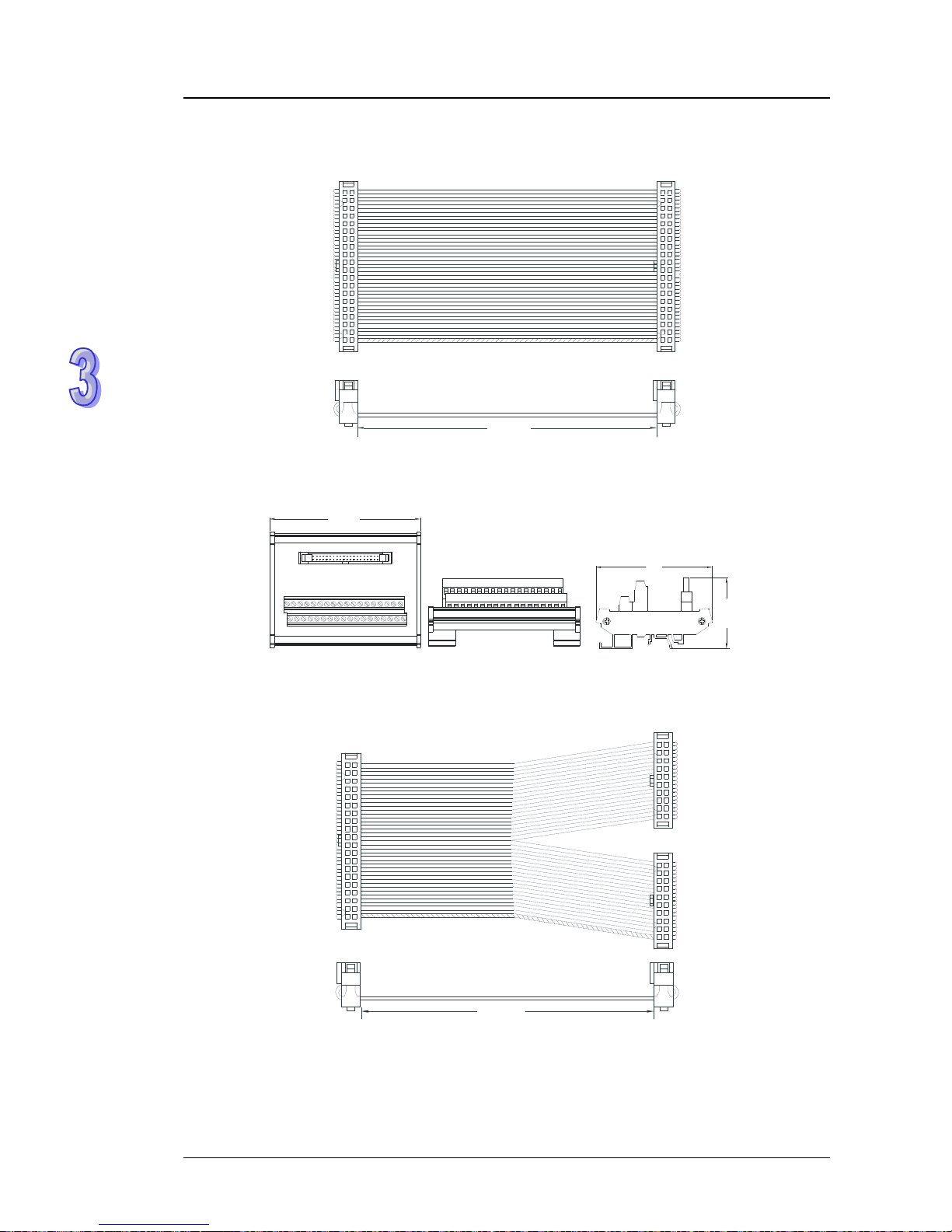
AH500 Hardware Manual
The latch connector, the I/O extension cable, and the external terminal module
The I/O extension cable DVPACAB7A10
100
12
12
39 4039 40
Unit: cm
The external terminal module for AH64AM10N-5C: DVPAETB-ID32A
113
87
53.6
Unit: mm
The I/O extension cable DVPACAB7B10
100
12
12
12
1
9
20
19 20
39 40
CN1
CN2
CN3
Unit: cm
3-25
Page 57

Chapter 3 Product Specifications
The external terminal module for AH64AN02T-5C: DVPAETB-OR16A
113
87
55.3
Unit: mm
The external terminal module for AH64AN02P-5C: DVPAETB-OR16B
113
87
55.3
Unit: mm
3-26
Page 58
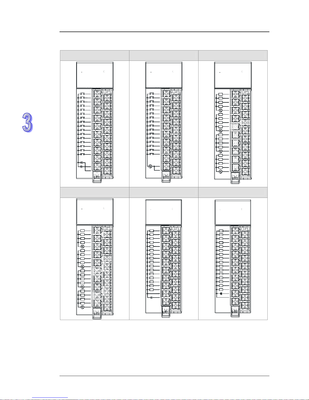
AH500 Hardware Manual
3-27
3.5.4 Arrangement of Input/Output Terminals
AH16AM10N-5A AH16AM30N-5A AH16AN01S-5A
7
10
12
11
9
8
6
5
4
3
2
15
14
6
7
13
S/S
24VDC 5mA
1
0
16AM10N
0231
5
4
S/S
98110 11 12 13 14 5
10347562
16AM30N
1
0
4
2
12
8
14
13
15
COM
7
120/240VAC
4.5/9mA
11
9
10
COM
5
3
6
98121513 1410 11
COM3
1
L
0
L
4
L
L
5
COM0
3
L
L
2
L
8
9
L
L
10
COM1
L
7
11
13
14
L
L
L
15
12
COM2
L
L
L
6
240VAC 0.5A
16AN01S
5
210436
7
981413 151110 12
AH16AN01R-5A AH16AN01T-5A AH16AN01P-5A
16AN01R
10432567
L
L
L
L
4
5
3
2
L
COM0
12
COM1
L
7
L
L
L
L
L
13
14
15
L
6
11
COM2
24VDC
/240VAC 2A
COM3
L
L
L
8
10
9
L
1
0
1110 1413 151289
11
213
109
51341267
14 15
0
2
L
L
L
L
L
0
8
1
3
4
16AN01T
9
8
7
6
10
12
13
11
ZP
UP
15
L
L
L
14
L
L
L
L
L
L
L
5
12~2 4VDC 0 .5A
L
11
16AN01P
0819210513341267
1514
L
0
1
3
L
L
4
L
L
2
12~2 4VDC 0.5 A
8
9
L
6
7
L
L
L
10
12
L
L
13
L
L
11
ZP
L
UP
15
L
14
L
5
Page 59

Chapter 3 Product Specifications
AH16AP11R-5A AH16AP11T-5A AH16AP11P-5A
COM1
1
0
10342 765
L
0
L
L
2
1
S/S
6
5
4
3
2
7
3
5
L
L
L
6
7
COM0
L
L
4
24VDC 5mA
240VAC 2A
16AP11R
10432
765
L
0
S/S
L
L
L
5
6
L
1
L
L
3
2
4
7
L
UP
ZP
0
24VDC 5mA
24VDC 0.5A
7
6
5
4
3
2
1
0
12 453 67
0
16AP11T
2145367
1
3
2
0
S/S
5
6
L
L
L
L
4
7
UP
ZP
L
L
L
L
24VDC 5mA
24VDC 0.5A
0
7
6
5
4
3
2
1
0
132645 7
16AP11P
0231645 7
AH32AM10N-5B AH32AN02T-5B
0.1
0.0 0.1
0.0
0.2 0.3 0.2 0.3
0.4 0.5 0.4 0.5
0.6 0.7 0.6 0.7
0.8 0.9 0.8 0.9
0.10 0.11 0.10 0.11
0.12 0.13 0.12 0.13
0.14 0.15 0.14 0.15
S/S S/S ZP ZP
NC 1.0 UP 1.0
1.1 1.2 1.1 1.2
1.3 1.4 1.3 1.4
1.5 1.6 1.5 1.6
1.7 1.8 1.7 1.8
1.9 1.10 1.9 1.10
1.11 1.12 1.11 1.12
1.13 1.14 1.13 1.14
1.15 S/S 1.15 ZP
S/S UP
32AN02T
102 54376
1413 1510 11 12
1413 1510 11 12
23 5467
8
8
01
9
9
12~24VDC 0.1A
24VD C 5mA
102 5437674513206
8
8
00
1413 1510 11 12
1413 1510 11 12
23546
7
1
9
9
745
1326
32AM10N
3-28
Page 60

AH500 Hardware Manual
AH32AN02P-5C AH64AM10N-5C
0.0 0.1 NC NC NC NC
0.2 0.3 S/S S/S 2.0 2.1
0.4 0.5 1.15 1.14 2.2 2.3
0.6 0.7 1.13 1.12 2.4 2.5
0.8 0.9 1.11 1.10 2.6 2.7
0.10 0.11 1.9 1.8 2.8 2.9
0.12 0.13 1.7 1.6 2.10 2.11
0.14 0.15 1.5 1.4 2.12 2.13
ZP ZP 1.3 1.2 2.14 2.15
UP 1.0 1.1 1.0 S/S S/S
1.1 1.2 NC NC NC NC
1.3 1.4 S/S S/S 3.0 3.1
1.5 1.6 0.15 0.14 3.2 3.3
1.7 1.8 0.13 0.12 3.4 3.5
1.9 1.10 0.11 0.10 3.6 3.7
1.11 1.12 0.9 0.8 3.8 3.9
1.13 1.14 0.7 0.6 3.10 3.11
1.15 ZP 0.5 0.4 3.12 3.13
UP 0.3 0.2 3.14 3.15
12~24VDC 0.1A
32AN02P
13
13
10 11 1289
10280191112
354
210543
14 15
14 15
67
76
0-34
-
7
24VDC 5mA
13
13
10 11 1289
10280191112
354
210543
64AM10N
14 15
14 15
67
76
0.1 0.0 S/S S/S
AH64AN02T-5C AH64AN02P-5C
UP UP 2.0 2.1 UP UP 2.0 2.1
ZP ZP 2.2 2.3 ZP ZP 2.2 2.3
1.15 1.14 2.4 2.5 1.15 1.14 2.4 2.5
1.13 1.12 2.6 2.7 1.13 1.12 2.6 2.7
1.11 1.10 2.8 2.9 1.11 1.10 2.8 2.9
1.9 1.8 2.10 2.11 1.9 1.8 2.10 2.11
1.7 1.6 2.12 2.13 1.7 1.6 2.12 2.13
1.5 1.4 2.14 2.15 1.5 1.4 2.14 2.15
1.3 1.2 ZP ZP 1.3 1.2 ZP ZP
1.1 1.0 UP UP 1.1 1.0 UP UP
UP UP 3.0 3.1 UP UP 3.0 3.1
ZP ZP 3.2 3.3 ZP ZP 3.2 3.3
0.15 0.14 3.4 3.5 0.15 0.14 3.4 3.5
0.13 0.12 3.6 3.7 0.13 0.12 3.6 3.7
0.11 0.10 3.8 3.9 0.11 0.10 3.8 3.9
0.9 0.8 3.10 3.11 0.9 0.8 3.10 3.11
0.7 0.6 3.12 3.13 0.7 0.6 3.12 3.13
0.5 0.4 3.14 3.15 0.5 0.4 3.14 3.15
0.3 0.2 ZP ZP 0.3 0.2 ZP ZP
4-70-3
13
13
10 11 1289
10280191112
354
210543
64AN02T
14 15
14 15
67
76
12~24VDC 0.1mA
0.1 0.0 UP UP
4-70-3
13
13
10 11 1289
10280191112
354
210543
64AN02P
14 15
14 15
67
76
12~24VDC 0.1mA
0.1 0.0 UP UP
3-29
Page 61

Chapter 3 Product Specifications
The DB37 connector and the external terminal module
1. The external terminal module for AH32AM10N-5B: DVPAETB-ID32B
Upper
row
X0 X2 X4 X6 X10 X12 X14 X16 X20 X22 X24 X26 X30 X32 X34 X36 S/S S/S
Lower
row
X1 X3 X5 X7 X1
1 X13 X15 X17 X21 X23 X25 X27 X31 X33 X35 X37 S/S S/S
2. The external terminal modules for AH32AN02T-5B
DVPAETB-OT32B
Upper
row
Y0 Y2 Y4 Y6 Y10 Y12 Y14 Y16 Y20 Y22 Y24 Y26 Y30 Y32 Y34 Y36 UP UP
Lower
row
Y1 Y3 Y5 Y7 Y11 Y13 Y15 Y17 Y21 Y23 Y25 Y27 Y31 Y33 Y35 Y37 ZP ZP
DVPAETB-OR32A
GND +24V
1st from
the left
C0 Y0 Y1 Y2 Y3 C1 Y4 Y5 Y6 Y7 C2 Y10 Y11 Y12 Y13 C3 Y14 Y15 Y16 Y17
21st from
the left
C4 Y20 Y21 Y22 Y23 C5 Y24 Y25 Y26 Y27 C6 Y30 Y31 Y32 Y33 C7 Y34 Y35 Y36 Y37
3-30
Page 62
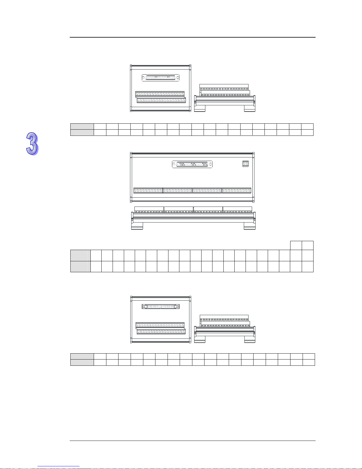
AH500 Hardware Manual
3. The external terminal modules for AH32AN02P-5B
DVPAETB-OT32B
Upper row Y0 Y2 Y4 Y6 Y10 Y12 Y14 Y16 Y20 Y22 Y24 Y26 Y30 Y32 Y34 Y36 UP UP
Lower row Y1 Y3 Y5 Y7 Y11 Y13 Y15 Y17 Y21 Y23 Y25 Y27 Y31 Y33 Y35 Y37 ZP ZP
DVPAETB-OR32B
GND +24V
1st from
the left
C0 Y0 Y1 Y2 Y3 C1 Y4 Y5 Y6 Y7 C2 Y10 Y11 Y12 Y13 C3 Y14 Y15 Y16 Y17
21st from
the left
C4 Y20 Y21 Y22 Y23 C5 Y24 Y25 Y26 Y27 C6 Y30 Y31 Y32 Y33 C7 Y34 Y35 Y36 Y37
The latch connector and the external terminal module
1. The external terminal module for AH64AM10N-5C: DVPAETB-ID32A
Upper row S/S S/S X0 X2 X4 X6 X10 X12 X14 X16 X20 X22 X24 X26 X30 X32 X34 X36
Lower row S/S S/S X1 X3 X5 X7 X11 X13 X15 X17 X21 X23 X25 X27 X31 X33 X35 X37
3-31
Page 63
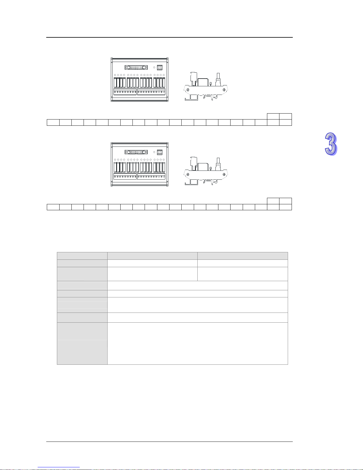
Chapter 3 Product Specifications
2. The external terminal module for AH64AN02T-5C: DVPAETB-OR16A
GND +24V
C0 Y0 Y1 Y2 Y3 C1 Y4 Y5 Y6 Y7 C2 Y10 Y11 Y12 Y13 C3 Y14 Y15 Y16 Y17
3. The external termin
al module for AH64AN02P-5C: DVPAETB-OR16B
GND +24V
C0 Y0 Y1 Y2 Y3 C1 Y4 Y5 Y6 Y7 C2 Y10 Y11 Y12 Y13 C3 Y14 Y15 Y16 Y17
3.6 Specifications for Analog Input/Output Modules
3.6.1 General Specifications
AH04AD-5A/AH08AD-5B
The electrical specifications
Module name AH04AD-5A AH08AD-5B
Number of inputs
4 8
Analog-to-digital
conversion
Voltage input/Current input Voltage input
Supply voltage
24 V DC (20.4 V DC~28.8 V DC) (-15%~+20%)
Connector type
Removable terminal block
Overall accuracy
25°C/77°F: The error is 0.5% of the input within the range
-20~60°C/-4~140°F: The error is 1% of the input within the range
Conversion time
150 μs/channel
There is isolation betwe
en an analog circuit and a digital circuit, but
there is no isolation between analog channels.
Isolation
Isolation between a digital circuit and a ground: 500 V DC
Isolation between an analog circuit and a ground: 500 V DC
Isolation between an analog circuit and a digital circuit: 500 V DC
Isolation between the 24 V DC and a ground: 500 V DC
3-32
Page 64

AH500 Hardware Manual
The functional specifications
Analog-to-digital
conversion
Voltage input
Rated input
range
-10 V~10 V 0 V~10 V ±5 V 0 V~5 V 1 V~5 V
Hardware
input range
-10.1 V~10.1 V -0.1 V~10.1 V -5.05 V~5.05 V -0.05 V~5.05 V 0.95 V~5.05 V
Hardware
resolution
16 bits
Input
impedance
>200 kΩ
Absolute
input range
±15 V
Analog-to-digital
conversion
Current input
Rated input
range
±20 mA 0m A~20 mA 4 mA~20 mA
Hardware
input range
-20.2 mA~20.2 mA -0.2 mA~20.2 mA 3.8 mA~20.2 mA
Hardware
resolution
16 bits
Input
impedance
250 Ω
Absolute
input range
±32 mA
AH04DA-5A/AH08DA-5B
The electrical specifications
Module name AH04DA-5A AH08DA-5B
Number of outputs
4 8
Analog-to-digital
conversion
Voltage output/Current output V oltage output
Supply voltage
24 V DC (20.4 V DC~28.8 V DC) (-15%~+20%)
Connector type
Removable terminal block
Overall accuracy
25°C/77°F: The error is 0.5% of the input within the range
-20~60°C/-4~140°F: The error is 1% of the input within the range
Conversion time
150 μs/channel
There is isolation betwe
en a digital circuit and an analog circuit, but
there is no isolation between analog channels.
Isolation
Isolation between a digital circuit and a ground: 500 V DC
Isolation between an analog circuit and a ground: 500 V DC
Isolation between an analog circuit and a digital circuit: 500 V DC
Isolation between the 24 V DC and a ground: 500 V DC
3-33
Page 65

Chapter 3 Product Specifications
The functional specifications
Analog-to-digital
conversion
Voltage output
Rated output
range
±10 V 0 V~10 V ±5 V 0 V~5 V 1 V~5 V
Hardware
output range
-10.1 V~10.1 V -0.1 V~10.1 V -5.05 V~5.05 V -0.05 V~5.05 V 0.95 V~5.05 V
Hardware
resolution
16 bits
Permissible
load
impedance
1 kΩ~2 MΩ: ±10 V and 0 V~10V
≧500 Ω: 1 V~5 V
Analog-to-digital
conversion
Current output
Rated output
range
0 mA~20 mA 4 mA~20 mA
Hardware
output range
-0.2 mA~20.2 mA 3.8 mA~20.2 mA
Hardware
resolution
16 bits
Permissible
load
impedance
≦550 Ω
AH06XA-5A
The electrical specifications
Module name AH06XA-5A
Number of inputs
4
Number of outputs
2
Analog-to-digital
conversion
Voltage input/Current input/Volt age output/Current output
24 V DC (20.4 V DC~28.8 V DC) (-1
5%~+20%)
Supply voltage
Connector type
Removable terminal block
Overall accuracy
25°C/77°F: The error is 0.5% of the input within the range
-20~60°C/-4~140°F: The error is 1% of the input within the range
Conversion time
150 us/channel
There is isolation betwe
en a digital circuit and an analog circuit, but
there is no isolation between analog channels.
Isolation
Isolation between a digital circuit and a ground: 500 V DC
Isolation between an analog circuit and a ground: 500 V DC
Isolation between an analog circuit and a digital circuit: 500 V DC
Isolation between the 24 V DC and a ground: 500 V DC
3-34
Page 66

AH500 Hardware Manual
The functional specifications for the analog-to-digital conversion
Analog-to-digital
conversion
Voltage input
Rated input
range
-10 V~10 V 0 V~10 V ±5 V 0 V~5 V 1 V~5 V
Hardware
input range
-10.1 V~10.1 V -0.1 V~10.1 V -5.05 V~5.05 V-0.05 V~5.05 V 0.95 V~5.05 V
Hardware
resolution
16 bits
Input
impedance
>200 kΩ
Absolute
input range
±15 V
Analog-to-digital
conversion
Current input
Rated input
range
±20 mA 0 mA~20 mA 4 mA~20 mA
Hardware
input range
-20.2 mA~20.2 mA -0.2 mA~20.2 mA 3.8 mA~20.2 mA
Hardware
resolution
16 bits
Input
impedance
250 Ω
Absolute
input range
±32 mA
The functional specifications for the digital-to-analog conversion
Digital-to-analog
conversion
Voltage output
Rated output
range
±10 V 0 V~10 V ±5 V 0 V~5 V 1 V~5 V
Hardware
output range
-10.1 V~10.1 V -0.1 V~10.1 V -5.05 V~5.05 V -0.05 V~5.05 V 0.95 V~5.05 V
Hardware
resolution
16 bits
Permissible
load
impedance
1 kΩ~2 MΩ: ±10 V and 0 V~10 V
≧500Ω: 1 V~5 V
Digital-to-analog
conversion
Current output
Rated output
range
0 mA~20 mA 4 mA~20 mA
Hardware
output range
-0.2 mA~20.2 mA 3.8 mA~20.2 mA
Hardware
resolution
16 bits
Permissible
load
impedance
≦550 Ω
3-35
Page 67

Chapter 3 Product Specifications
3.6.2 Profiles
AH04AD-5A/AH08AD-5B/AH04DA-5A/AH08DA-5B/AH06XA-5A
RUN
ERROR
04AD
SG
ZP
UP
-10~+10V
-20~+20mA
VI0
I3
VI3
I1
I2
V3
VI2
V2
V1
VI1
I0
V0
1
2
3
4
7
6
8
9
10
5
FE
-10~+10V
FE
VO6
AG
ZP
UP
AG
VO7
AG
AG
VO5
AG
VO4
RUN
AG
VO3
VO2
AG
AG
VO1
ERROR
VO0
08DA
V3
V3
V2
V2
RUN
ERROR
08AD
V0
V1
V1
V0
-10~+10V
SLD
SLD
V7
V4
V4
SLD
V5
V7
V6
V6
V5
SLD
RUN
ERROR
04DA
SLD
SLD
SLD
UP
SLD
ZP
SG
-10~+10V
0/4~+ 20mA
SG
AG
IO3
VO3
AG
IO2
AG
AG
VO2
IO1
VO1
IO0
VO0
10V, 20 mA
10V,0/4~20mA
AI
06XA
RUN
ERROR
AO
ZP
UP
SG
VI0
AG
IO1
VO1
VO0
IO0
VI3
I3
I1
I2
V3
VI2
V2
V1
VI1
I0
V0
Number Name Description
1 Model name Model name of the module
RUN LED
indicator
Operating status of the module
ON: The module is running.
OFF: The module stops running.
2
ERROR LED
indicator
Error status of the module
ON: A serious error occurs in the module.
OFF: The module is normal.
Blink: A slight error occurs in the module.
3
Removable
terminal block
The inputs are connected to sensors.
The outputs are connected to loads which will be driven.
3-36
Page 68

AH500 Hardware Manual
3-37
Number Name Description
4
Arrangement of
the input/output
terminals
Arrangement of the terminals
5
Description of the
inputs/outputs
Simple specifications for the module
6 Clip Removing the terminal block
7 Label Nameplate
8 Set screw Fixing the module
9 Connector Connecting the module and a backplane
10 Projection Fixing the module
3.6.3 Dimensions
AH04AD-5A/AH08AD-5B/AH04DA-5A/AH08DA-5B/AH06XA-5A
35
103
110
114
6
FE
-10~+10V
FE
VO6
AG
ZP
UP
AG
VO7
AG
AG
VO5
AG
VO4
RUN
AG
VO3
VO2
AG
AG
VO1
ERROR
VO0
08DA
V3
V3
V2
V2
RUN
ERROR
08AD
V0
V1
V1
V0
-10~+10V
SLD
SLD
V7
V4
V4
SLD
V5
V7
V6
V6
V5
SLD
RUN
ERROR
04DA
SLD
SLD
SLD
UP
SLD
ZP
SG
-10~+10V
0/4~+2 0mA
SG
AG
IO3
VO3
AG
IO2
AG
AG
VO2
IO1
VO1
IO0
VO0
10V, 20mA
10V,0/4~20mA
AI
06XA
RUN
ERROR
AO
ZP
UP
SG
VI0
AG
IO1
VO1
VO0
IO0
VI3
I3
I1
I2
V3
VI2
V2
V1
VI1
I0
V0
RUN
ERROR
04AD
SG
ZP
UP
-10~+10V
-20~+20mA
VI0
I3
VI3
I1
I2
V3
VI2
V2
V1
VI1
I0
V0
Unit: mm
Page 69

Chapter 3 Product Specifications
3.6.4 Arrangement of Input/Output Terminals
AH04AD-5A AH08AD-5B AH04DA-5A
RUN
ERROR
04AD
SG
ZP
UP
-10~+10V
-20~+20mA
VI0
I3
VI3
I1
I2
V3
VI2
V2
V1
VI1
I0
V0
V3
V3
V2
V2
RUN
ERROR
08AD
V0
V1
V1
V0
-10~+10V
SLD
SLD
V7
V4
V4
SLD
V5
V7
V6
V6
V5
SLD
RUN
ERROR
04DA
SLD
SLD
SLD
UP
SLD
ZP
SG
-10~+10V
0/4~+20mA
SG
AG
IO3
VO3
AG
IO2
AG
AG
VO2
IO1
VO1
IO0
VO0
AH08DA-5B AH06XA-5A
ERROR
08DA
RUN
ZP
SG
UP
SG
-10~+10V
AG
VO7
AG
VO6
AG
VO5
AG
AG
VO4
AG
VO3
AG
AG
VO2
VO1
VO0
±10V,±20mA
±10V,0/4~20mA
AI
06XA
RUN
ERROR
AO
ZP
UP
SG
VI0
AG
IO1
VO1
VO0
IO0
VI3
I3
I1
I2
V3
VI2
V2
V1
VI1
I0
V0
3-38
Page 70

AH500 Hardware Manual
3.7 Specifications for Temperature Measurement
Modules
3.7.1 General Specifications
AH04PT-5A
The electrical specifications
Number of analog
inputs
4
Three-wire configuratio
n: Pt100/Ni100/Pt1000/Ni1000 sensor, and
0~300 Ω input impedance
Applicable sensor
Four-wire configuration: Pt100/Ni100/Pt1000/Ni1000 sensor, and 0~300
Ω input impedance
Pt100: DIN 43760-1980 JIS C1604-1989; 100 Ω 3850 PPM/°C
Pt1000: DIN EN60751; 1 kΩ 3850 PPM/°C
Ni100/Ni1000: DIN 43760
Supply voltage
24 V DC (20.4 V DC~28.8 V DC) (-1
5%~+20%)
Connector type
Removable terminal block
Overall accuracy
25°C/77°F: The error is 0.5% of the input within the range
-20~60°C/-4~140°F: The error is 1% of the input within the range
Conversion time
Four-wire configuration: 150 ms/channel
Three-wire configuration: 300 ms/channel
Isolation
There is isolation between a digital circuit and an analog circuit, and
there is isolation between analog channels.
Isolation between a digital circuit and a ground: 500 V DC
Isolation between an analog circuit and a ground: 500 V DC
Isolation between an analog circuit and a digital circuit: 500 V DC
Isolation between the 24 V DC and a ground: 500 V DC
The functional specifications
Analog-to-digital
conversion
Centigrade (°C) Fahrenheit (°F)
Input
impedance
Rated input range
Pt100: -180°C~800°C
Ni100: -80°C~170°C
Pt1000: -180°C~800°C
Ni1000: -80°C~170°C
Pt100: -292°F~1,472°F
Ni100: -112°F~338°F
Pt1000: -292°F~1,472°F
Ni1000: -112°F~338°F
0~300 Ω
Average function
Range: 1~100
Self-diagnosis
Disconnection detection
AH04TC-5A/AH08TC-5A
The electrical specifications
Module name AH04TC-5A AH08TC-5A
Number of analog
inputs
4 8
Applicable sensor
Type J, type K, type R, type S, type T, type E, and type N thermocouples
±150 mV voltage inputs
Supply voltage
24 V DC (20.4 V DC~28.8 V DC) (-15%~+20%)
Connector type
Removable terminal block
Overall accuracy
25°C/77°F: The error is 0.5% of the input within the range
-20~60°C/-4~140°F: The error is 1% of the input within the range
Conversion time
200 ms/channel
Isolation
There is isolation between a digital circuit and an analog circuit, and
there is isolation between analog channels.
3-39
Page 71

Chapter 3 Product Specifications
3-40
Module name AH04TC-5A AH08TC-5A
Isolation between a digital circuit and a ground: 500 V DC
Isolation between an analog circuit and a ground: 500 V DC
Isolation between an analog circuit and a digital circuit: 500 V DC
Isolation between the 24 V DC and a ground: 500 V DC
Isolation between analog channels: 120 V AC
The functional specifications
Analog-to-digital
conversion
Centigrade (°C)
Fahrenheit(°F)
Voltage input
Rated input range
Type J: -100°C~1,150°C
Type K: -100°C~1,350°C
Type R: 0°C~1,750°C
Type S: 0°C~1,750°C
Type T: -150°C~390°C
Type E: -150°C~980°C
Type N: -150°C~1,280°C
Type J: -148°F~2,102°F
Type K: -148°F~2,462°F
Type R: 32°F~3,18 2°F
Type S: 32°F~3,182°F
Type T: -238°F~734°F
Type E: -238°F~1,796°F
Type N: -238°F~2,336°F
±150 mV
Average function
Range: 1~100
Self-diagnosis
Disconnection detection
3.7.2 Profiles
AH04PT-5A/AH04TC-5A/AH08TC-5A
I1
O1
O0
I3
O3
I0
RUN
ERROR
O2
I2
I0
FG
I1
04PT
O0
FG
O1
I3
I2
FG
O2
FG
RTD
2/3/4-WIRE
O3
1
2
3
4
7
6
8
9
10
5
I3
FG
FG
I3
Thermocouple
J,K,R,S,T,E,N
I2
I2
I1
I1
I0
I0
08TC
RUN
ERROR
I6
I5
I5
I4
I7
FG
I7
I6
FG
I4
I0
I0
04TC
I3
FG
FG
I3
RUN
ERROR
I2
I2
I1
I1
Thermocouple
J,K,R,S,T,E,N
Number Name Description
1 Model name Model name of the module
2
RUN LED
indicator
Operating status of the module
ON: The module is running.
OFF: The module stops running.
2
ERROR LED
indicator
Error status of the module
ON: A serious error occurs in the module.
OFF: The module is normal.
Blink: A slight error occurs in the module.
3
Removable
terminal block
The inputs are connected to a sensor.
4
Arrangement of
the input
terminals
Arrangement of the terminals
Page 72

AH500 Hardware Manual
3-41
Number Name Description
5
Description of the
inputs
Simple specifications for the module
6 Clip Removing the terminal block
7 Label Nameplate
8 Set screw Fixing the module
9 Connector Connecting the module and a backplane
10 Projection Fixing the module
3.7.3 Dimensions
AH04PT-5A/AH04TC-5A/AH08TC-5A
110
114
35
6
103
I1
O1
O0
I3
O3
I0
RUN
ERROR
O2
I2
I0
FG
I1
04PT
O0
FG
O1
I3
I2
FG
O2
FG
RTD
2/3/4 -WIRE
O3
I3
FG
FG
I3
Thermocouple
J,K,R,S,T,E,N
I2
I2
I1
I1
I0
I0
08TC
RUN
ERROR
I6
I5
I5
I4
I7
FG
I7
I6
FG
I4
I0
I0
04TC
I3
FG
FG
I3
RUN
ERROR
I2
I2
I1
I1
Thermocouple
J,K,R,S,T,E,N
Unit: mm
3.7.4 Arrangement of Input/Output Terminals
AH04PT-5A AH04TC-5A AH08TC-5A
I1
O1
O0
I3
O3
I0
RUN
ERROR
O2
I2
I0
FG
I1
04PT
O0
FG
O1
I3
I2
FG
O2
FG
RTD
2/3/4-WIRE
O3
I0
I0
04TC
I3
FG
FG
I3
RUN
ERROR
I2
I2
I1
I1
Thermocouple
J,K,R,S,T,E,N
I3
FG
FG
I3
Thermocouple
J,K,R,S,T,E,N
I2
I2
I1
I1
I0
I0
08TC
RUN
ERROR
I6
I5
I5
I4
I7
FG
I7
I6
FG
I4
Page 73

Chapter 3 Product Specifications
3.8 Specifications for Network Modules
3.8.1 General Specifications
AH10SCM-5A
Item Specifications
Connector type
European-style removable terminal block
Transmission
interface
RS-485⁄RS-422
1,200, 2,400, 4,800, 9,600, 19,200,
38,400, 57,600, 76,800, 115,200,
230,400, and 460,800 bps
Transmission
speed
Communication
format
Stop bit: 1 bit and 2 bits
Parity bit: none, an odd parity bit, and an even parity bit
Data bit: 7 bits and 8 bits
Communication
protocol
Modbus ASCII/RTU
UD Link
BACnet MS/TP slave
Electric energy
consumption
1.5 W
Insulation voltage
2,500 V DC
AH10EN-5A
Item Specifications
Connector type
RJ-45 with auto-MDI/MDIX
Transmission
interface
802.3 and 802.3u
Category 5e cabl
e
Transmission
cable
The maximum length is 100 meters.
Transmission
speed
10/100 Mbps auto-detection
Communication
protocol
ICMP, IP, TCP, UDP, DHCP, NTP, Modbus TCP, HTTP, SNMP, and
SMTP
Electric energy
consumption
1.5 W
Insulation voltage
2,500 V DC
AH10DNET-5A
Item Specifications
Communication
type
CAN
Electrical
isolation
500 V DC
Connector type
Removable connector (5.08 mm)
I/O polled, and explicit
Data type
Communication
speed
Standard mode: 125 kbps, 250 kbps, and 500 kbps
Extended mode: 10 kbps, 20 kbps, 50 kbps, 125 kbps, 250 kbps, 500
kbps, 800 kbps, and 1 Mbps
Communication
cable
Delta shielded twisted pair
(Two communication cables, two power cables, and one shielded cable)
3-42
Page 74
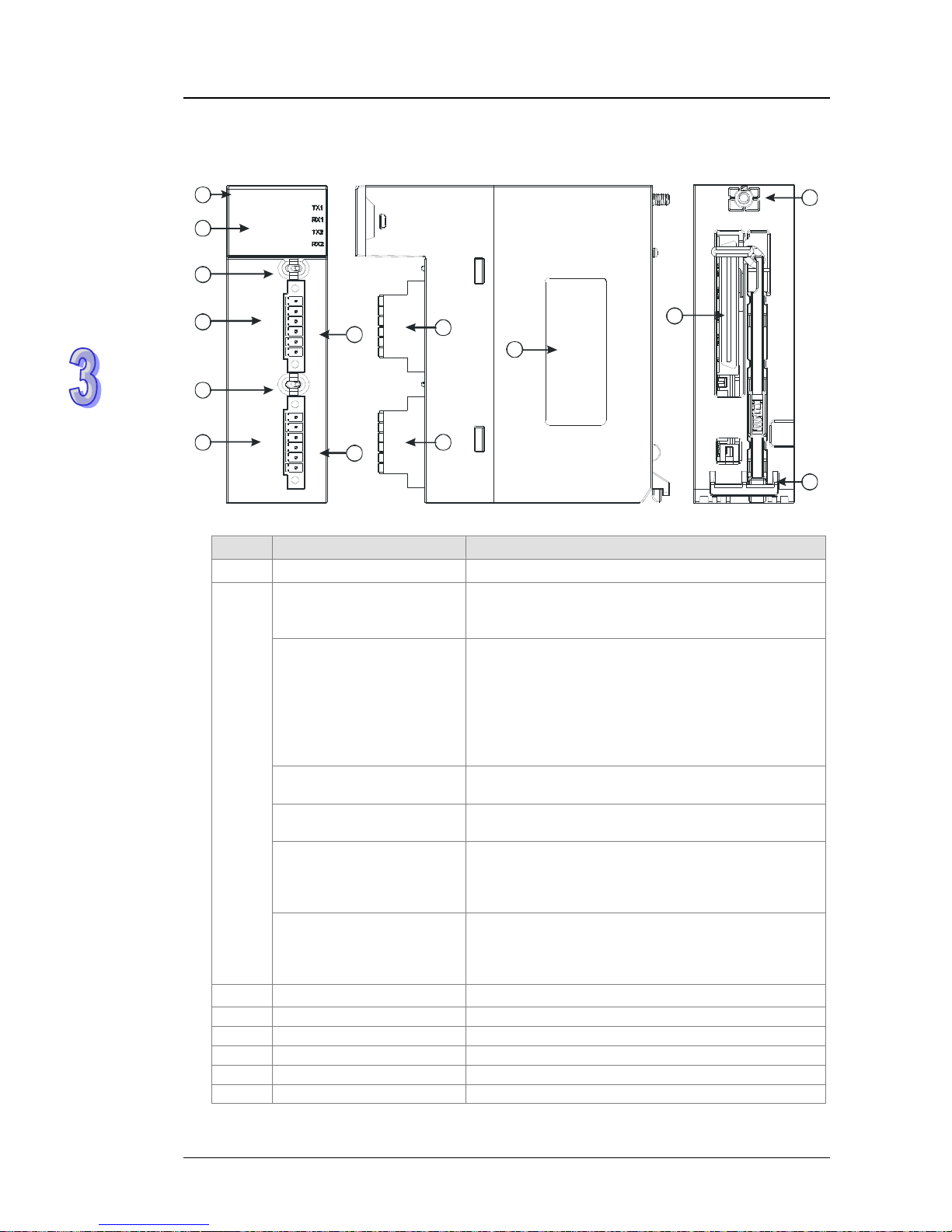
AH500 Hardware Manual
3.8.2 Profiles
AH10SCM-5A
D+
D-
ONTR 2
COM2
TX+
RX+
RX-
TX-
OFF
D+
D-
10SCM
RX+
RX-
COM1
TX-
TX+
TR 1 O N
COM2 RS485
COM1 RS485
RUN
ERROR
OFF
GND
FG
FG
GND
GND
FG
GND
FG
1
12
2
3
4
7
13
6
8
9
11
10
5
9
Number Name Description
1 Model name Model name of the module
RUN LED indicator (green)
Operating status of the module
ON: The module is running.
OFF: The module stops running.
ERROR LED indicator (red)
Error status of the module
ON: There is a hardware error.
OFF: The module is normal.
Blink: 1. The setting of the module is incorrect, or there
is a communication error.
2. Restoring the module to the default factory
value
COM1 (RS-485) LED
indicator (green)
ON: RS-485 mode
OFF: RS-422 mode
COM2 (RS-485) LED
indicator (green)
ON: RS-485 mode
OFF: RS-422 mode
TX1/TX2 LED indicator
(orange)
Blink: The data is being transmitted through the
RS-485/RS422 port.
OFF: The data is not being transmitted through the
RS-485/RS422 port.
2
RX1/RX2 LED indicator
(orange)
Blink: The data is being reveived through the
RS-485/RS422 port.
OFF: The data is not being reveived through the
RS-485/RS422 port.
3 Switch of terminal resistor 1 Switching terminal resistor 1 ON/OFF
4 Terminals Terminals for COM1 (RS-422)
5 Terminals Terminals for COM1 (RS-485)
6 Switch of terminal resistor 2 Switching terminal resistor 2 ON/OFF
7 Terminals Terminals for COM2 (RS-422)
8 Terminals Terminals for COM2 (RS-485)
3-43
Page 75

Chapter 3 Product Specifications
3-44
Number Name Description
9
European-style terminal
block
Terminals for wiring
10 Label Nameplate
11 Set screw Fixing the module
12 Connector Connecting the module and a backplane
13 Projection Fixing the module
AH10EN-5A
10EN
Ethernet
NS
MS
X2
X1
1
12
2
3
4
7
13
6
8
9
11
10
14
5
Number Name Description
1 Model name Model name of the module
2
Seven-segment
display
Display
3
LINK LED
indicator
LINK LED indicator for RJ45 port 1
4
ACK LED
indicator
ACK LED indicator for RJ45 port 1
5
LINK LED
indicator
LINK LED indicator for RJ45 port 2
6
ACK LED
indicator
ACK LED indicator for RJ45 port 2
7 NS LED indicator LED indicator
8 MS LED indicator LED indicator
9 RJ45 port 1 RJ45 port 1
10 RJ45 port 2 RJ45 port 2
11 Label Nameplate
12 Set screw Fixing the module
13 Connector Connecting the module and a backplane
14 Projection Fixing the module
Page 76

AH500 Hardware Manual
AH10DNET-5A
IN 1
IN 0
DR 1
DR 0
10DNET
Node Address
x10
x10
NS
MS
1
12
2
3
4
7
6
8
9
11
10
5
Number Name Description
1 Model name Model name of the module
2
Seven-segment
display
Display
3 Address knob Setting the address
4 Function switch Setting the functions
5
DeviceNet
connector
DeviceNet is used to interconnect control devices for data
exchange.
6 MS LED indicator Indicating the status of the module
7 NS LED indicator Indicating the status of the network
8
Removable terminal
block
Terminals for wiring
9 Label Nameplate
10 Set screw Fixing the module
11 Connector Connecting the module and a backplane.
12 Projection Fixing the module
The address knobs
It is used to set the node address of AH10DNET-5ª on a DeviceNet network. (Node addresses
range from 0 to 63.)
Setting Description
0…63
Available nodes on a
DeviceNet network
Unavail
able node
s on a
DeviceNet network
64…99
Example: If users want to set the communication address of AH10 DNE T-5A to 26, they can turn
the knob corresponding to x10
1
to 2, and turn the knob corresponding to x100 to 6.
Note:
1. When the power supply is cut off, the node address is set. After the setting of the node
address is complete, AH10 DNET-5A can be supplied with power.
2. If AH10DNET-5A is running, changing the node address is unavailable.
3. Please use a slotted screwdriver to turn the knobs with care, and do not scrape them.
3-45
Page 77
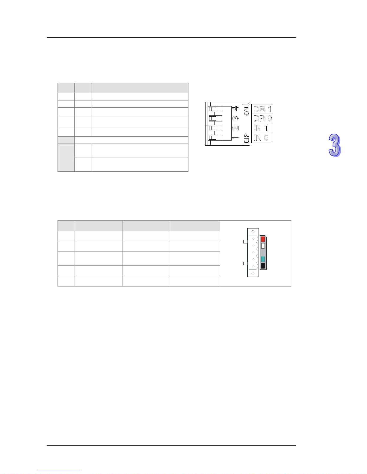
Chapter 3 Product Specifications
The function switch
The function switch provides the following functions:
1. Setting the working mode (IN 0)
2. Setting the transmission speed of a DeviceNet network (DR 0~DR 1)
DR 1 DR 0 Transmission speed
OFF OFF 125 kbps
OFF ON 250 kbps
ON OFF 500 kbps
ON ON
Entering the extendable serial
transmission speed mode
IN 1
Reserved
ON
If the slave is disconnected, the
previous I/O data is retained.
IN 0
OFF
If the slave is disconnected, the
previous I/O data is cleared.
Note:
1. When the power supply is cut off, the functions are set. After the setting of the functions i s
complete, AH10DNET-5A can be supplied with power.
2. If AH10DNET-5A is running, changing the functions is unavailable.
3. Please use a slotted screwdriver to adjust the DIP switch with care, and do not scrape them.
The DeviceNet connector
Pin Signal Color Description
5 V+ Red 24 V DC
4 CAN_H White Signal +
-
It is connected to a
shielded cable.
3 Ground
2 CAN_L Blue Signal -
1 V- Black 0 V DC
1
2
3
4
5
3-46
Page 78

AH500 Hardware Manual
3-47
3.8.3 Dimensions
AH10SCM-5A
110
3
5
6
103
D+
D-
ONTR2
COM2
TX+
RX+
RX-
TX-
OFF
D+
D-
10SCM
RX+
RX-
COM1
TX-
TX+
TR1 ON
COM2 RS485
COM1 RS485
RUN
ERROR
OFF
GND
FG
FG
GND
GND
FG
GND
FG
Unit: mm
AH10EN-5A
X2
X1
Ethernet
NS
MS
10EN
110
35
6
103
Unit: mm
Page 79
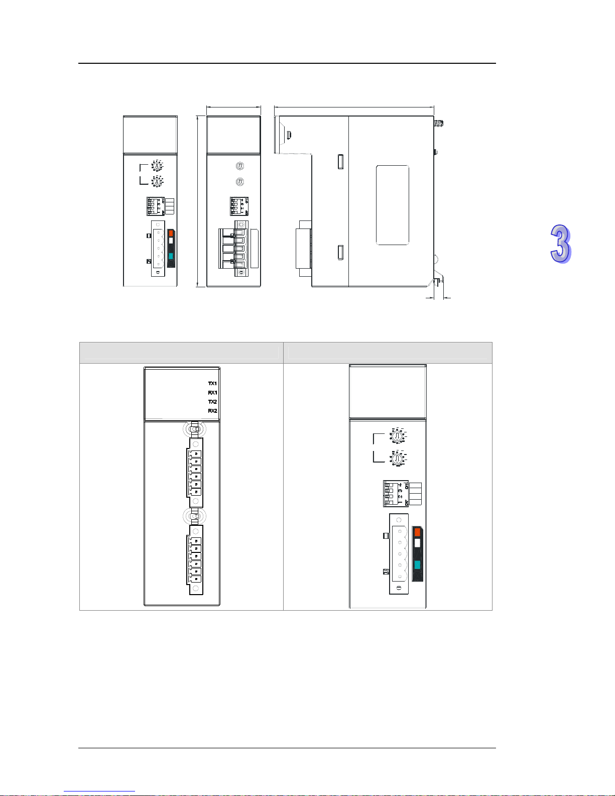
Chapter 3 Product Specifications
AH10DNET-5A
IN 1
IN 0
DR 1
DR 0
x10
0
x10
1
NS
Node Addres s
MS
10DNET
110
3
5
6
103
Unit: mm
3.8.4 Arrangement of Input/Output Terminals
AH10SCM-5A AH10DNET-5A
D+
D-
ON
TR 2
COM2
TX+
RX+
RX-
TX-
OFF
D+
D-
10SCM
RX+
RX-
COM1
TX-
TX+
TR 1
ON
COM2 RS485
COM1 RS485
RUN
ERROR
OFF
GND
FG
FG
GND
GND
FG
GND
FG
IN 1
IN 0
DR 1
DR 0
x10
0
x10
1
NS
Node A ddr es s
MS
10DNET
3-48
Page 80

AH500 Hardware Manual
3.9 Specifications for Motion Control Modules
3.9.1 General Specifications
AH02HC-5A
Item Specifications
2 channels
Number of channels
Input
(differential
input)
CH0: X0.8+, X0.8-, X0.9+, and X0.9CH1: X0.10+, X0.10-, X0.11+, and X0.11-
Pulse/Directi
on (one phase and one input)
Pulse format
Counting up/Counting down (one phase and two inputs)
One time the frequency of A/B-phase inputs (two phases and
two inputs)
Four times the frequency of A/B-phase inputs (two phases and
two inputs)
Input signal
Signal level
5~24 V DC
Maximum
frequency of
counting
The maximum frequency is 200 kHz.
The number of sample
d pulses is within the range between
-200000 and 200000.
Range
The number of accumulated pulses is within the range between
-99999999 and 99999999.
The number of input pulses is within the range between
-2147483648 and 2147483648.
Specifications
General count
Type
Circular count
Input
(differential
input)
CH0: X0.0+ and X0.0CH1: X0.1+ and X0.1-
Signal level
5~24 V DC
RESET input
Maximum
current
15 mA
Output type
CH0: The high-speed pulse output Y0.8 is a transistor whose
collector is an open collector .
CH1: The high-speed pulse output Y0.9 is a transistor whose
collector is an open collector .
Signal level
24 V DC
Comparison
output
Maximum
current
15 mA
3-49
Page 81

Chapter 3 Product Specifications
AH04HC-5A
Item Specifications
4 channels
Number of channels
Input
(differential
input)
CH0: X0.8+, X0.8-, X0.9+, and X0.9CH1: X0.10+, X0.10-, X0.11+, and X0.11CH2: X0.12+, X0.12-, X0.13+, and X0.13CH3: X0.14+, X0.14-, X0.15+, and X0.15Pulse/Directi
on (one phase and one input)
Pulse format
Counting up/Counting up (one phase and two inputs)
One time the frequency of A/B-phase inputs (two phases and
two inputs)
Four times the frequency of A/B-phase inputs (two phases and
two inputs)
Input signal
Signal level
5~24 V DC
Maximum
frequency of
counting
The maximum frequency is 200 kHz.
The number of sample
d pulses is within the range between
-200000 and 200000.
Range
The number of accumulated pulses is within the range between
-99999999 and 99999999.
The number of input pulses is within the range between
-2147483648 and 2147483648.
Specifications
General count
Type
Circular count
Input
(differential
input)
CH0: X0.0+ and X0.0CH1: X0.1+ and X0.1CH2: X0.2+ and X0.2CH3: X0.3+ and X0.3-
Signal level
5~24V DC
RESET input
Maximum
current
15 mA
Output type
CH0: The high-speed pulse output Y0.8 is a transistor whose
collector is an open collector .
CH1: The high-speed pulse output Y0.9 is a transistor whose
collector is an open collector .
CH2: The high-speed pulse output Y0.10 is a transistor whose
collector is an open collector .
CH3: The high-speed pulse output Y0.11 is a transistor whose
collector is an open collector .
Signal level
24 V DC
Comparison
output
Maximum
current
15 mA
3-50
Page 82

AH500 Hardware Manual
AH05PM-5A
Specifications
Item
AH05PM-5A
Number of axes
2 axes
Storage
The capacity of the built-in storage is 64 ksteps.
Unit
Motor unit Compound unit Mechanical unit
Connection with a CPU
module
Users can set the initial register involved in the data exchange in a
CPU module, and the number of registers involved in the data
exchange in the CPU module. Four hundred data registers at most
can be involved in the data exchange.
There are three types of pulse output modes. These modes adopt
the differential output.
Motor control
1. Pulse/Direction
2. Counting up/Counting down
3. A/B-phase output
Maximum speed
Single axis: 500 kpps
Multi-axis interpolation: 500 kpps
Input
signal
Detector
X0.0, X0.1, X0.8, X0.9, X0.12, and X0.13
Output
signal
Servo output
signal
Y0.0+, Y0.0-, Y0.2+, Y0.2-, Y0.1+, Y0.1-, Y0.3+, Y0.3-, Y0.8, and
Y0.9
External communication
port
Mini USB port
Number of basic
instructions
27
Number of applied
instructions
130
OX0~99 (motion subroutine/positioning program): M02 (The
execution of the program stops. (END))
M-code
M00~M01, M03~M101, and M103~M65535:
The execution of the program pauses. (WAIT)
Users can use them freely.
G-code
G0 (rapid positioning), G1 (linear interpolation), G2 (circular
interpolation, clockwise), G3 (circular interpolation,
counterclockwise), G4 (dwell), G17 (XY plane selection), G90
(absolute programming), and G91 (incremental programming)
3-51
Page 83

Chapter 3 Product Specifications
The description of the terminals
Maximum input
Terminal
Response
characteristic
Description
Current Voltage
X0.0, X0.1,
X0.8, X0.9,
X0.12, and
X0.13
1. They are single/A/B-phase inputs.
2. The functions of the terminals:
Motion control:
X0.0 is the PG input for axis 1, and
X0.1 is the PG input for axis 2.
X0.12 is the DOG input for axis 1,
and X0.13 is the DOG input for
axis 2.
X0.8 and X0.9 are for a manual
pulse generator.
High-speed count:
X0.0 is the RESET input for
counter 0.
X0.8 is an A-phase input for
counter 0, and X0.9 is a B-phase
input for counter 0.
High-speed comparison and catch: The
terminals can function as trigger
signals for a high-speed catch.
Interrupt inputs
200 kHz 15 mA 24 V
Y0.8 and
Y0.9
1. The high-speed pulse outputs are
transistors whose collectors are open
collector.
2. The functions of the terminals:
Motion control: Y0.8 is the CLEAR
output for axis 1, and Y0.9 is the
CLEAR output for axis 2.
High-speed comparison and catch: The
high-speed comparison outputs
provide the PWM function.
200 kHz 15 mA 24 V
Y0.0+, Y0.0-,
Y0.1+, Y0.1-,
Y0.2+, Y0.2-,
Y0.3+, and
Y0.3-
1. They are differential outputs.
2. The function of the terminals:
Motion control:
Y0.0+ and Y0.0- are A-phase
outputs for axis 1. Y0.2+ and Y0.2are A-phase outputs for axis 2.
Y0.1+ and Y0.1- are B-phase
outputs for axis 1. Y0.3+ and Y0.3are B-phase outputs for axis 2.
1 MHz 5 mA 5 V
3-52
Page 84

AH500 Hardware Manual
AH10PM-5A
Specifications
Item
AH10PM-5A
Number of axes
6 axes
Storage
The capacity of the built-in storage is 64 ksteps.
Unit
Motor unit Compound unit Mechanical unit
Connection with a CPU
module
Users can set the initial register involved in the data exchange in a
CPU module, and the number of registers involved in the data
exchange in the CPU module. Four hundred data registers at most
can be involved in the data exchange.
There are three types of pulse output modes. These modes adopt
the differential output.
Motor control
1. Pulse/Direction
2. Counting up/Counting down
3. A/B-phase output
Maximum speed
Single axis: 500 kpps
Multi-axis interpolation: 500 kpps
Operating
switch
STOP/RUN (automatic/manual switch)
Input signal
Detector
X0.8, X0.9, X0.10, X0.11, X0.12, X0.13, X0.14, X0.15, X0.0+, X0.0-,
X0.1+, X0.1-, X0.2+, X0.2-, X0.3+, and X0.3-
Output signal
Servo
output
signal
Y0.0+, Y0.0-, Y0.2+, Y0.2-, Y0.4+, Y0.4-, Y0.6+, Y0.6-, Y0.1+, Y0.1-,
Y0.3+, Y0.3-, Y0.5+, Y0.5-, Y0.7+, Y0.7-, Y0.8, Y0.9, Y0.10, and
Y0.11
External communication
port
Mini USB port
Ethernet port
Expansion storage
device
Mini SD card
The maximum capacity is 32 GB.
Number of basic
instructions
27
Number of applied
instructions
130
OX0~99 (motion subroutine/positioning program): M02 (The
execution of the program stops. (END))
M-code
M00~M01, M03~M101, and M103~M65535:
The execution of the program pauses. (WAIT)
Users can use them freely.
G-code
G0 (rapid positioning), G1 (linear interpolation), G2 (circular
interpolation, clockwise), G3 (circular interpolation,
counterclockwise), G4 (dwell), G17 (XY plane selection), G18 (ZX
plane selection), G19 (YZ plane selection), G90 (absolute
programming), and G91 (incremental programming)
3-53
Page 85

Chapter 3 Product Specifications
The description of the terminals
Maximum input
Terminal
Response
characteristic
Description
Current Voltage
1. They are diff
erential inputs.
X0.0+, X0.0-,
X0.1+, X0.1-,
X0.2+, X0.2-,
X0.3+, and
X0.3-
2. The functions of the terminals:
Motion control: They are the PG inputs
for axis 1~axis 4.
High-speed counter: X0.0+ and X0.0-
are the RESET inputs for counter 0.
X0.1+ and X0.1- are the RESET inputs
for counter 1. X0.2+ and X0.2- are the
RESET inputs for counter 2 and
counter 4. X0.3+ and X0.3- are the
RESET inputs for counter 3 and
counter 5.
High-speed comparison and catch:
The terminals can function as trigger
signals for a high-speed catch.
Interrupt inputs
200 kHz 15 mA 5~24 V
X0.8 and
X0.9
1. They are single/A/B-phase inputs.
2. The functions of the terminals:
Motion control: The terminals are for a
manual pulse generator.
High-speed count:
The terminals are for counter 0.
X0.8 is an A-phase input for
counter 0, and X0.9 is a B-phase
input for counter 0.
High-speed comparison and catch:
The terminals can function as trigger
signals for a high-speed catch.
Interrupt inputs
200 kHz 15 mA 24 V
X0.10, X0.11,
X0.12, X0.13,
X0.14, and
X0.15
1 They are single/A/B-phase inputs.
2 The functions of the terminals:
Motion control: They are the DOG
inputs for axis 1~axis 6.
High-speed counter:
The terminals are for counter
1~counter 5.
X0.10 is an A-phase input for
counter 1, X0.12 is an A-phase
input for counter 2 and counter 4,
and X0.14 is an A-phase input for
counter 3 and counter 5.
X0.11 is a B-phase input for
counter 1, X0.13 is a B-phase
input for counter 2 and counter 4,
and X0.15 is a B-phase input for
counter 3 and counter 5.
High-speed comparison and catch:
The terminals can function as trigger
signals for a high-speed catch.
Interrupt inputs
200 kHz 15 mA 24 V
3-54
Page 86

AH500 Hardware Manual
3-55
Maximum input
Terminal Description
Response
characteristic
Current Voltage
Y0.8, Y0.9,
Y0.10, and
Y0.11
1. The high-speed pulse outputs are
transistors whose collectors are open
collector.
2. The functions of the terminals:
Motion control:
The terminals are the CLEAR
outputs for axis 1~axis 4, and
provide the PWM function.
Y0.8 and Y0.9 are for axis 5. Y0.10
and Y0.1 1 are for axis 6. Y0.8 is an
A-phase output for axis 5, and
Y0.10 is an A-phase output for axis
6. Y0.9 is a B-phase output for axis
5, and Y0.11 is a B-phase output
for axis 6.
High-speed comparison and catch:
The high-speed comparison outputs
provide the PWM function.
200 kHz 15 mA 24 V
Y0.0+, Y0.0-,
Y0.1+, Y0.1-,
Y0.2+, Y0.2-,
Y0.3+, Y0.3-,
Y0.4+, Y0.4-,
Y0.5+, Y0.5-,
Y0.6+, Y0.6-,
Y0.7+, and
Y0.7-
1. They are differential outputs.
2. The function of the terminals:
Motion control:
The terminals are for axis 1~axis
4.
Y0.0+ and Y0.0- are A-phase
outputs for axis 1. Y0.2+ and Y0.2are A-phase outputs for axis 2.
Y0.4+ and Y0.4- are A-phase
outputs for axis 3. Y0.6+ and Y0.6are A-phase outputs for axis 4.
Y0.1+ and Y0.1- are B-phase
outputs for axis 1. Y0.3+ and Y0.3are B-phase outputs for axis 2.
Y0.5+ and Y0.5- are B-phase
outputs for axis 3. Y0.7+ and Y0.7are B-phase outputs for axis 4.
Y0.0+ and Y0.0- are the CLEAR
outputs for axis 5. Y0.1+ and Y0.1are the CLEAR outputs for axis 6.
1 MHz 5 mA 5 V
Page 87

Chapter 3 Product Specifications
AH20MC-5A
Specifications
Item
AH20MC-5A
Number of axes
12 axes
Storage
The capacity of the built-in storage is 64 ksteps.
Unit
Motor unit Compound unit Mechanical unit
Connection with a CPU
module
Users can set the initial register involved in the data exchange in a
CPU module, and the number of registers involved in the data
exchange in the CPU module. Four hundred data registers at most
can be involved in the data exchange.
Delta high-speed motion control system DMCNET (Delta Motion
Control Network)
Motor control
The response time is one millisecond.
Maximum speed
Single axis: 500 kpps
Two-axis interpolation: 500 kpps
Operating
switch
STOP/RUN (automatic/manual switch)
Input signal
Detector
X0.10+, X0.10-, X0.11+, X0.11-, X0.12+, X0.12-, X0.13+, X0.13-,
X0.14+, X0.14-, X0.15+, X0.15, X0.0+, X0.0-, X0.1+, X0.1-, X0.2+,
X0.2-, X0.3+, X0.3-, X0.8+, X0.8-, X0.9+, and X0.9-
Output signal
Servo
output
signal
Y0.8+, Y0.8-, Y0.9+, Y0.9-, Y0.10+, Y0.10-, Y0.11+ and Y0.11-
External communication
port
Mini USB port
Ethernet port
DMCNET port
Expansion storage
device
Mini SD card
The maximum capacity is 32 GB.
Number of basic
instructions
27
Number of applied
instructions
130
OX0~99 (motion subroutine/positioning program): M02 (The
execution of the program stops. (END))
M-code
M00~M01, M03~M101, and M103~M65535:
The execution of the program pauses. (WAIT)
Users can use them freely.
G-code
G0 (rapid positioning), G1 (linear interpolation), G2 (circular
interpolation, clockwise), G3 (circular interpolation,
counterclockwise), G4 (dwell), G17 (XY plane selection), G18 (ZX
plane selection), G19 (YZ plane selection), G90 (absolute
programming), and G91 (incremental programming)
3-56
Page 88

AH500 Hardware Manual
The description of the terminals
Maximum input
Response
characteristic
Terminal Description
Current Voltage
X0.0+, X0.0-,
X0.1+, X0.1-,
X0.2+, X0.2-,
X0.3+, and
X0.3-
1. They are differential inputs.
2. The functions of the terminals:
High-speed count:
The terminals are the RESET
inputs for counter 0~counter
5.
X0.0+ and X0.0- are for
counter 0. X0.1+ and X0.1are for counter 1. X0.2+ and
X0.2- are for counter 2 and
counter 4. X0.3+ and X0.3are for counter 3 and counter
5.
High-speed comparison and
catch: The terminals can function
as trigger signals for a high-speed
catch.
Interrupt inputs
200 kHz 15 mA 5~24 V
X0.8+, X0.8-,
X0.9+, and
X0.9-
1. They are differential inputs.
2. The functions of the terminals:
Motion control: The terminals are
for a manual pulse generator .
High-speed count:
The terminals are for counter
0.
X0.8+ and X0.8- are A-phase
inputs for counter 0. X0.9+
and X0.9- are B-phase inputs
for counter 0.
High-speed comparison and
catch: The terminals can function
as trigger signals for a high-speed
catch.
Interrupt inputs
200 kHz 15 mA 5~24 V
3-57
Page 89

Chapter 3 Product Specifications
3-58
Maximum input
Terminal Description
Response
characteristic
Current Voltage
X0.10+, X0.10-,
X0.11+, X0.11-,
X0.12+, X0.12-,
X0.13+, X0.13,
X0.14+, X0.14-,
X0.15+, and
X0.15-
1. They are differential inputs.
2. The functions of the terminals:
High-speed count:
The terminals are for counter
1~counter 5.
X0.10+ an X0.10- are
A-phase inputs for counter 1.
X0.12+ and X0.12- are
A-phase inputs for counter 2
and counter 4. X0.14+ and
X0.14- are A-phase inputs for
counter 3 and counter 5.
X0.11+ and X0.11- are
B-phase inputs for counter 1.
X0.13+ and X0.13- are
B-phase inputs for counter 2
and counter 4. X0.15+ and
X0.15- are B-phase inputs for
counter 3 and counter 5.
High-speed comparison and
catch: The terminals can function
as trigger signals for a high-speed
catch.
Interrupt inputs
200 kHz 15 mA 5~24 V
Y0.8, Y0.9,
Y0.10, and
Y0.11
1. The high-speed pulse outputs are
transistors whose collectors are
open collector.
2. The function of the terminals:
High-speed comparison and
catch: The high-speed
comparison outputs provide the
PWM function.
200 kHz 15 mA 24 V
Page 90
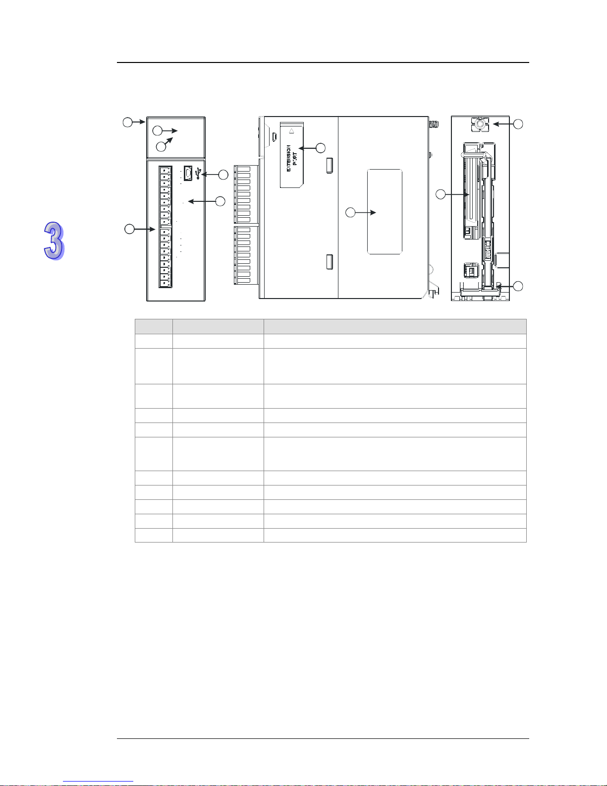
AH500 Hardware Manual
3.9.2 Profiles
AH02HC-5A
1
4
8
7
5
2
3
6
9
11
10
02HC
ERROR
RUN
C0
Y0.8
Y0.9
C1
X0.8
+
X0.8
-
X0.9+
X0.9
-
X0.10+
X0.10
-
X0.11+
X0.11
-
X0.0+
X0.0
-
X0.1
-
X0.1+
Number Name Description
1 Model name Model name of the module
2
RUN LED indicator
(green)
Operating status of the module
ON: The module is running.
OFF: The module stops running.
3
ERROR LED
indicator (red)
Error status of the module
Blink: The module is abnormal.
4 USB port Providing the mini USB communication interface
5 Terminals Input/Output terminals
6
Arrangement of the
input/output
terminals
Arrangement of the terminals
7 Extension port Updating the firmware
8 Label Nameplate
9 Set screw Fixing the module
10 Connector Connecting the module and a backplane
11 Projection Fixing the module
3-59
Page 91

Chapter 3 Product Specifications
AH04HC-5A
04HC
CN1
ERROR
RUN
1
2
3
4
7
6
8
9
10
5
Number Name Description
1 Model name Model name of the module
2
RUN LED indicator
(green)
Operating status of the module
ON: The module is running.
OFF: The module stops running.
3
ERROR LED
indicator (red)
Error status of the module
Blink: The module is abnormal.
4 USB port Providing the mini USB communication interface
5 Connector Connecting the module and an I/O extension cable
6 Extension port Updating the firmware
7 Label Nameplate
8 Set screw Fixing the module
9 Connector Connecting the module and a backplane
10 Projection Fixing the module
3-60
Page 92

AH500 Hardware Manual
AH05PM-5A
05PM
Y0.3+
COM
Y0.3
-
Y0.8
Y0.9
X0.13
Y0.1
-
Y0.2+
Y0.2
-
Y0.0+
Y0.0
-
Y0.1+
X0.8
X0.9
X0.12
S/S
X0.0
X0.1
RUN
ERROR
1
4
8
7
5
2
3
6
9
11
10
Number Name Description
1 Model name Model name of the module
2
RUN LED indicator
(green)
Operating status of the module
ON: The module is running.
OFF: The module stops running.
3
ERROR LED
indicator (red)
Error status of the module
Blink: The module is abnormal.
4 USB port Providing the mini USB communication interface
5 Terminals Input/Output terminals
6
Arrangement of the
input/output
terminals
Arrangement of the terminals
7 Extension port Updating the firmware
8 Label Nameplate
9 Set screw Fixing the module
10 Connector Connecting the module and a backplane
11 Projection Fixing the module
3-61
Page 93

Chapter 3 Product Specifications
AH10PM-5A
10PM
Micro SD
Ethernet
RUN
STOP
ERROR
ETH
RUN
CN1
1
12
2
3
4
7
13
6
8
9
11
10
14
5
Number Name Description
1 Model name Model name of the module
2
RUN LED indicator
(green)
Operating status of the module
ON: The module is running.
OFF: The module stops running.
3
ERROR LED
indicator (red)
Error status of the module
Blink: The module is abnormal.
4
Ethernet connection
LED indicator
(green)
Status of the Ethernet connection
ON: The Ethernet connection is being connected.
OFF: The Ethernet connection is disconnected.
5 USB port Providing the mini USB communication interface
6 RUN/STOP switch
RUN: The user program is executed.
STOP: The execution of the user program stops.
7 SD slot Providing the SD interface
8 Connector Connecting the module and an I/O extension cable
9 Ethernet port Providing the Ethernet communication interface
10 Extension port Updating the firmware
11 Label Nameplate
12 Set screw Fixing the module
13 Connector Connecting the module and a backplane
14 Projection Fixing the module
3-62
Page 94

AH500 Hardware Manual
AH20MC-5A
20MC20MC
Micro SD
DMCNetEthernet
CN1
NET
ETH
ERROR
RUN
NET
ETH
ERROR
RUN
RUN
STOP
1
12
2
3
4
7
13
6
8
9
11
10
14
15
5
16
Number Name Description
1 Model name Model name of the module
2
RUN LED indicator
(green)
Operating status of the module
ON: The module is running.
OFF: The module stops running.
3
ERROR LED
indicator (red)
Error status of the module
Blink: The module is abnormal.
4
Ethernet connection
LED indicator
(green)
Status of the Ethernet connection
ON: The Ethernet connection is being connected.
OFF: The Ethernet connection is disconnected.
5
DMCNET
connection LED
indicator
(green)
Status of the DMCNET connection
ON: The DMCNET connection is being connected.
OFF: The DMCNET connection is disco nnected.
6 USB port Providing the mini USB communication interface
7 RUN/STOP switch
RUN: The user program is executed.
STOP: The execution of the user program stops.
8 SD slot Providing the SD interface
9 Connector Connecting the module and an I/O extension cable.
10 DMCNET port Providing the DMCNET communication interface
11 Ethernet port Providing the Ethernet communication interface
12 Extension port For updating the firmware
13 Label Nameplate
14 Set screw Fixing the module
15 Connector Connecting the module and a backplane
16 Projection Fixing the module
3-63
Page 95
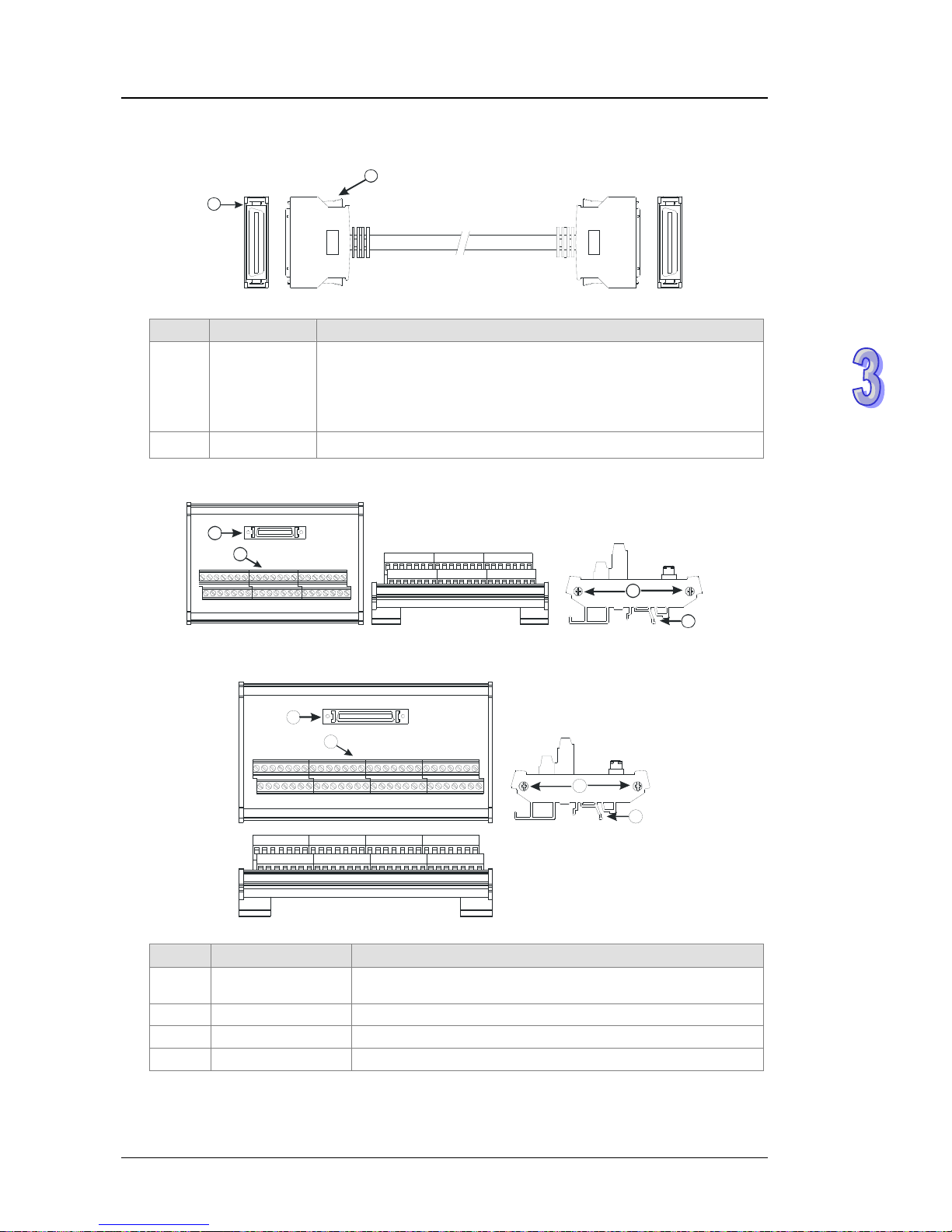
Chapter 3 Product Specifications
The I/O extension cable, and the external terminal module
1. The I/O extension cable DVPACAB7D10/DVPACAB7E10
2
1
Number Name Description
1 Connector
Connecting a motion control module and an external terminal
module
DVPACAB7D10 is a 36-pin I/O extension cable for AH04HC-5A and
AH20MC-5A.
DVPACAB7E10 is a 50-pin I/O extension cable for AH10PM-5A.
2 Clip Fixing the connector
2. The external terminal module for AH04HC-5A and AH20MC-5A: DVPAETB-IO16C
3
4
2
1
3. The external terminal module for AH10PM-5A: DVPAETB-IO24
3
4
2
1
Number Name Description
1 Connector
Connecting the external terminal module and a motion control
module
2 Terminals Input/Output terminals for wiring
3 Clip Hanging the external terminal module on a DIN rail
4 Set screw Fixing the base
3-64
Page 96

AH500 Hardware Manual
3.9.3 Dimensions
AH02HC-5A
02HC
ERROR
RUN
C0
Y0.8
Y0.9
C1
X0.8
+
X0.8
-
X0.9+
X0.9
-
X0.10+
X0.10
-
X0.11+
X0.11
-
X0.0+
X0.0
-
X0.1-
X0.1+
110
3
5103
6
Unit: mm
AH
04HC
-5A
04HC
CN1
ERROR
RUN
110
35
6
103
Unit: mm
3-65
Page 97

Chapter 3 Product Specifications
AH05PM-5A
110
3
5103
05PM
Y0.3+
COM
Y0.3
-
Y0.8
Y0.9
X0.13
Y0.1
-
Y0.2+
Y0.2
-
Y0.0+
Y0.0
-
Y0.1+
X0.8
X0.9
X0.12
S/S
X0.0
X0.1
RUN
ERROR
6
Unit: mm
AH10PM-5A
10PM
Micro SD
Ethernet
RUNSTOP
ERROR
ETH
RUN
CN1
110
35
6
10
3
Unit: mm
3-66
Page 98

AH500 Hardware Manual
AH20MC-5A
20MC20MC
Micro S D
DMCNet
Ethernet
CN1
NET
ETH
ERROR
RUN
NET
ETH
ERROR
RUN
RUN
STOP
110
3
5
6
10
3
Unit: mm
The I/O exte
nsion cable, and the e
xternal terminal module
1. The 36-pin I/O extension cable for AH04HC-5A and AH20MC-5: DVPACAB7D10
100
Unit: cm
2. The external terminal module for AH04HC-5A and AH20MC-5A: DVPAETB-IO16C
125
87
50.8
Unit: mm
3. The 50-pin I/O extension cable for AH10PM-5A: DVPACAB7E10
100
Unit: cm
3-67
Page 99

Chapter 3 Product Specifications
4. The external terminal module for AH10PM-5A: DVPAETB-IO24
157
87
50.8
Unit: mm
3.9.4 Arrangement of Input/Output Terminals
AH02HC-5A AH05PM-5A
02HC
ERROR
RUN
C0
Y0.8
Y0.9
C1
X0.8
+
X0.8
-
X0.9 +
X0.9
-
X0.10+
X0.10
-
X0.11+
X0.11
-
X0.0 +
X0.0
-
X0.1 -
X0.1 +
●
●
05PM
Y0.3+
COM
Y0.3
-
Y0.8
Y0.9
X0.13
Y0.1
-
Y0.2+
Y0.2
-
Y0.0+
Y0.0
-
Y0.1+
X0.8
X0.9
X0.12
S/S
X0.0
X0.1
RUN
ERROR
AH04HC-5A
Pin Terminal Pin Terminal Pin Terminal Pin Terminal
1 X0.8+ 2 X0.8- 3 X0.9+ 4 X0.95 X0.0+ 6 X0.0- 7 X0.10+ 8 X0.10-
9 X0.11+ 10 X0.11- 11 X0.1+ 12 X0.113 X0.12+ 14 X0.12- 15 X0.13+ 16 X0.1317 X0.2+ 18 X0.2- 19 X0.14+ 20 X0.1421 X0.15+ 22 X0.15- 23 X0.3+ 24 X0.325 N/C 26 N/C 27 N/C 28 N/C
29 Y0.8 30 C0 31 Y0.9 32 C1
04HC
ERROR
RUN
33 Y0.10 34 C2 35 Y0.11 36 C3
3-68
Page 100

AH500 Hardware Manual
AH10PM-5A
Pin Terminal Pin Terminal Pin Terminal Pin Terminal
50 X0.0+ 49 X0.0- 48 X0.1+ 47 X0.146 X0.2+ 45 X0.2- 44 X0.3+ 43 X0.342 N/C 41 N/C 40 N/C 39 N/C
38 X0.8 37 X0.9 36 X0.10 35 X0.11
34 X0.12 33 X0.13 32 X0.14 31 X0.15
30 S/S 29 N/C 28 N/C 27 N/C
26 Y0.0+ 25 Y0.0- 24 Y0.1+ 23 Y0.122 Y0.2+ 21 Y0.2- 20 Y0.3+ 19 Y0.318 Y0.4+ 17 Y0.4- 16 Y0.5+ 15 Y0.514 Y0.6+ 13 Y0.6- 12 Y0.7+ 11 Y0.710 N/C 9 N/C 8 Y0.8 7 C0
6 Y0.9 5 C1 4 Y0.10 3 C2
10PM
ERROR
ETH
RUN
2 Y0.11 1 C3
AH20MC-5A
Pin Terminal Pin Terminal Pin Terminal Pin Terminal
36 X0.8+ 35 X0.8- 34 X0.9+ 33 X0.932 X0.0+ 31 X0.0- 30 X0.10+ 29 X0.1028 X0.11+ 27 X0.11- 26 X0.1+ 25 X0.124 X0.12+ 23 X0.12- 22 X0.13+ 21 X0.1320 X0.2+ 19 X0.2- 18 X0.14+ 17 X0.1416 X0.15+ 15 X0.15- 14 X0.3+ 13 X0.312 N/C 11 N/C 10 N/C 9 N/C
8 Y0.8 7 C0 6 Y0.9 5 C1
20MC20MC
NET
ETH
ERROR
RUN
NET
ETH
ERROR
RUN
4 Y0.10 3 C2 2 Y0.11 1 C3
The external terminal module
1. The external terminal module for AH04HC-5A: DVPAETB-IO16C
C3 C2 C1 C0 N/C N/C X0.3- X0.15- X0.14- X0.2- X0.13- X0.12- X0.1- X0.11- X0.10- X0.0- X0.9- X0.8- 24G 24G FE
Y0.11 Y0.10 Y0.9 Y0.8 N/C N/C X0.3+ X0.15+X0.14+ X0.2+X0.13+X0.12+ X0.1+ X0.11+X0.10+ X0.0+ X0.9+ X0.8+ N/C 24V 24V
3-69
 Loading...