

Delta AHCPU560-EN2 Series, AHCPU5X1-EN Series, AHCPU511-EN, AH10EN-5A Series, AHCPU531-EN Operation Manual
...Page 1

Industrial Automation Headquarters
Delta Electronics, Inc.
Taoyuan Technology Center
No.18, Xinglong Rd., Taoyuan City,
Taoyuan County 33068, Taiwan
TEL: 886-3-362-6301 / FAX: 886-3-371-6301
Asia
Delta Electronics (Jiangsu) Ltd.
Wujiang Plant 3
1688 Jiangxing East Road,
Wujiang Economic Development Zone
Wujiang City, Jiang Su Province, P.R.C. 215200
TEL: 86-512-6340-3008 / FAX: 86-769-6340-7290
Delta Greentech (China) Co., Ltd.
238 Min-Xia Road, Pudong District,
ShangHai, P.R.C. 201209
TEL: 86-21-58635678 / FAX: 86-21-58630003
Delta Electronics (Japan), Inc.
Tokyo Ofce
2-1-14 Minato-ku Shibadaimon,
T
okyo 105-0012, Japan
TEL: 81-3-5733-1111 / FAX: 81-3-5733-1211
Delta Electronics (Korea), Inc.
1511, Byucksan Digital Valley 6-cha, Gasan-dong,
Geumcheon-gu, Seoul, Korea, 153-704
TEL: 82-2-515-5303 / FAX: 82-2-515-5302
Delta Electronics Int’l (S) Pte Ltd.
4 Kaki Bukit Ave 1, #05-05, Singapore 417939
TEL: 65-6747-5155 / FAX: 65-6744-9228
Delta Electronics (India) Pvt. Ltd.
Plot No 43 Sector 35, HSIIDC
Gurgaon, PIN 122001, Haryana, India
TEL : 91-124-4874900 / FAX : 91-124-4874945
EtherNet/IP
Operation Manual
Americas
Delta Products Corporation (USA)
Raleigh Ofce
P.O. Box 12173,5101 Davis Drive,
Research Triangle Park, NC 27709, U.S.A.
TEL: 1-919-767-3800 / FAX: 1-919-767-8080
Delta Greentech (Brasil) S.A.
Sao Paulo Ofce
Rua Itapeva, 26 - 3° andar Edicio Itapeva One-Bela Vista
01332-000-São Paulo-SP-Brazil
TEL: 55 11 3568-3855 / FAX: 55 11 3568-3865
Europe
Delta Electronics (Netherlands) B.V.
Eindhoven Ofce
De Witbogt 20, 5652 AG Eindhoven, The Netherlands
TEL : +31 (0)40-8003800 / FAX : +31 (0)40-8003898
IA-0269420-03
*We reserve the right to change the information in this manual without prior notice.
2019/05/13
www.deltaww.com
Page 2

Version
Revision
Date
1st
The first version was published.
2016/05/20
2nd
1.Information concerning AHCPU5X1-EN is added in
7.New product information is added in section 9.2.
added in chapter 9.
3rd
EtherNet/IP Operation Manual
Revision His tory
section 1.3.1.
2.Information concerning AHCPU5X1-EN is added in
section 2.1.
3.Information concerning AHCPU5X1-EN and
AHCPU-ETHN-5A is added in chapter 3.
4.Information concerning AH-RTU series is added in
section 4.4 and 4.6.
5.Information concerning TAG is added in section 5.1 and
5.2.
6.Information concerning AHCPU5X1-EN and
AHCPU-ETHN-5A is added in chapter 8.
1.Updates on ISPSoft version, information concerning
AHCPU501-EN, AHRTU-ETHN-5A and AHCPU560-EN2 is
added in chapter 1.
2.Information concerning AHCPU501-EN, AHRTU-ETHN-5A
and AHCPU560-EN2 is added in chapter 2.
3.Information on Ethernet specifications of AHCPU501-EN
and AHCPU560-EN2 is added in chapter 3. New content
regarding maximum transmission speed of Delta
products and calculating CIP connection is added in
section 3.2.4 and 3.2.5
4.Information on ISPSoft version is updated and
descriptions concerning AHCPU501-EN and
AHCPU560-EN2 is added in chapter 4.
5.Notes for error code classification is added in section
6.1 and correct all error code ‘H’ to ‘16#’.
6.New EI P product information and updated content are
2017/03/31
2019/05/13
Page 3

EtherNet/IP Operation Manual
Table of Contents
Chapter 1 Product Introduction
1.1 Introduction ...................................................................................... 1-2
1.1.1 EtherNet/IP ................................................................................... 1-2
1.2 Definition ........................................................................................... 1-2
1.3 Features ............................................................................................ 1-3
1.3.1 Delta EIP Architecture ..................................................................... 1-3
1.3.2 Product Features ............................................................................ 1-4
Chapter 2 Netwo rk Installation
2.1 EtherNet/IP Device ........................................................................ 2-2
2.2 Network Installation ....................................................................... 2-2
2.2.1. Single Port Device .......................................................................... 2-2
2.2.2. Dual Port Device ............................................................................ 2-3
2.2.2. PC Software .................................................................................. 2-4
Chapter 3 Product Specifications
3.1 Ethernet Specifications ................................................................... 3-2
3.1.1 AHCPU5x1-EN/ AHCPU560-EN2 ....................................................... 3-2
3.1.2 AH10EN-5A ................................................................................... 3-2
3.1.3 AHRTU-ETHN-5A ............................................................................ 3-2
3.2 Ethernet/IP Specifications ............................................................. 3-3
3.2.1 AHCPU5x1-EN/ AHCPU560-EN2 ....................................................... 3-3
3.2.2 AH10EN-5A ................................................................................... 3-4
3.2.3 AHRTU-ETHN-5A ............................................................................ 3-4
3.2.4 Maximum Transmission Speed of Delta Products ................................ 3-5
3.2.5 Calcu lating CIP Connection .............................................................. 3-6
i
Page 4

Chapter 4 EIP Builder
4.1 Access EIP Builde r .......................................................................... 4-2
4.1.1 Setting Up EIP Scanner ...................................................................4-2
4.2 Set up the IP Address ..................................................................... 4-4
4.2.1 IP Address Types ............................................................................4-4
4.2.2 Set up the IP Address (Static IP) ......................................................4-5
4.2.3 Set up the IP Address (BOOTP/DHCP) ...............................................4-6
4.2.4 IP Modification (BOOTP/DHCP) ....................................................... 4-11
4.3 Network ....................................................................................... 4-13
4.4 Data Mapping ............................................................................... 4-23
4.5 Diagnosis ...................................................................................... 4-28
4.6 AH Series – Connect to a RTU module .......................................... 4-30
4.6.1 AHCPU5x1-EN Series/AHCPU560-EN2 .............................................. 4-30
Chapter 5 Programming
5.1. DFB_EIP_EXP Function Block ......................................................... 5-2
5.1.1 Parameters .........................................................................................5-2
5.2. TAG Function .................................................................................. 5-7
5.2.1 Produced TAG .................................................................................5-7
5.2.2 Consumed TAG ...............................................................................5-9
Chapter 6 Troubleshooting
6.1 Troubleshooting ............................................................................. 6-2
6.2 Error Code & How to fix them ......................................................... 6-2
6.2.1 Ha rd war e E rr or ...............................................................................6-2
6.2.2 Configuration Error ..........................................................................6-3
6.2.3 Applicatio n Error .............................................................................6-5
Chapter 7 Studio 5000 Software O peration
7.1 Architecture ................................................................................... 7-2
7.2 Create a New Project ..................................................................... 7-2
ii
Page 5

7.3 Create a S canner ............................................................................ 7-4
7.3.1 Create a New Module ...................................................................... 7-4
7.4 Connect to a Delta Adapter ............................................................. 7-6
7.4.1 Import an EDS file .......................................................................... 7-6
7.4.2 Create an Adapter .......................................................................... 7-8
7.5 Download ..................................................................................... 7-11
7.6 Data Mapping ............................................................................... 7-12
Chapter 8 CIP Object
8.1 Object List ...................................................................................... 8-3
8.2 Data Type ....................................................................................... 8-5
8.3 Identity Object (Class ID: 16#01) .................................................. 8-7
8.4 Message Router Object (Class ID: 16#02) ..................................... 8-8
8.5 Assembly Object (Class ID: 16#04) ............................................... 8-9
8.5.1 AHCPU5x1-EN and AH10EN-5A ........................................................ 8-9
8.5.2 AHRTU-ETHN-5A ........................................................................... 8-11
8.6 Connection Manager Object (Class ID: 16#06) ............................ 8-12
8.7 Device Level Ring Object (Class ID: 16#47) ................................. 8-13
8.8 QoS Object (Class ID: 16#48) ...................................................... 8-16
8.9 Port Object (Class ID: 16#F4) ...................................................... 8-17
8.10 TCP/IP Interface Object (Class ID: 16#F5) .................................. 8-18
8.11 Ethernet Link Object (Class ID: 16#F6) ....................................... 8-20
8.12 Vendor Specific Objects ................................................................ 8-24
8.12.1 X Register (Class ID: 16#350) ........................................................ 8-24
8.12.2 Y Register (Class ID: 16#351) ........................................................ 8-25
8.12.3 D Register (Class ID: 16#352) ....................................................... 8-26
8.12.4 M Register (Class ID: 16#353) ....................................................... 8-27
8.12.5 S Register (Class ID: 16#354) ........................................................ 8-27
8.12.6 T Register (Class ID: 16#355) ........................................................ 8-28
8.12.7 C Register (Class ID: 16#356) ........................................................ 8-29
iii
Page 6

8.12.8 HC Register (Class ID: 16#357) ..................................................... 8-30
8.12.9 SM Register (Class ID: 16#358) ..................................................... 8-30
8.12.10 SR Register (Class ID: 16#359) ..................................................... 8-31
8.12.11 Control Register (Class ID: 16#370) ............................................... 8-31
8.12.12 Status Register (Class ID: 16#370) ................................................ 8-33
8.12.13 Input Register (Class ID: 16 # 3 7 1) .................................................. 8-34
8.12.14 Output Register (Class ID: 16#372) ............................................... 8-36
8.12.15 RTU AI Register (Class ID:16#373) ............................................... 8-36
8.12.16 RTU AO Register (Class ID:16#374) .............................................. 8-37
8.12.17 RTU DI Register (Class ID:16#375) ............................................... 8-37
8.12.18 RTU DO Register (Class ID:16#376) .............................................. 8-38
Chapter 9 Delta EIP Product List
9.1 Delta EIP Products ......................................................................... 9-2
9.2 Delta EIP Products, DLR (Device Level Ring) supported ................. 9-2
9.3 Delta EIP Products, Scanner supported .......................................... 9-2
iv
Page 7

1
Chapter 1 Product Introduction
Table of Contents
1.1 Introduction…..…………………….……………………………………………………………… 1-2
1.1.1 EtherNet/IP……………………………………………………………………………………………………………… 1-2
1.2 Definition………………………………………………………………………….………………… 1-2
1.3 Features…………………………………………………………………………………………..… 1-3
1.3.1 Delta EIP Architecture……………………………………………………………………………………………. 1-3
1.3.2 Product Features……………………………………………………………………………………………………. 1-4
1-1
Page 8

EtherNet/IP Operation Manual
_1
1.1 Introduction
1.1.1 EtherNet/IP
EtherNet/IP (“IP” st ands for “Industrial P rot oco l” ) is an industrial Ethernet network managed by ODV A, Inc. (formerly Open
DeviceNet Vendors Association, Inc.), a global trade and standards development organization.
EtherNet/IP works on a TCP/UDP/IP based Ethernet network and uses most widely deployed collections of Ethernet
standards to provide a broad range of applications in different industries that require high-speed and stability including
Factory Automation (FA), Building Automation (BA), Process Automation (PA) and many more.
Delta covers a full range of controller and drive products supported by EtherNet/IP, including Programmable Logic
Controllers (PLC), inverters, Human Machine Interfaces (HMI) and so on. Refer to section 9.1 for a full product list
supported by EtherNet/IP. In addition, users can also use the EDS file to connect to the EtherNet/IP devices of other
brands. Delta EtherNet/IP software, the EIP Builder, can be called or run independently through the ISPSoft v3.06.
1.2 Definition
Term Definition
ODVA Open DeviceNet Vendor Association for EtherNet/IP
EtherNet/IP, an industrial Ethernet network, provides interoperability for system providers. IP
EIP
I/O Connection Via the I/O connection to connect to EtherNet/IP and to exchange data cyclically.
Explicit Message
RPI
ACD Address Conflict Detection to detect IP address duplications.
Produced/Consumed
TAG (P/C TAG)
stands for Industrial Protocol. The term “EIP” (EtherNet/IP) will be used throughout this
manual.
Connect to EtherNet/IP and to exchange data non-cyclically. Data will be exchanged piece
by piece via instructions.
Requested Packet Interval, via the I/O connection to connect to EtherNet/IP to exchange
data at regular time intervals.
TAGs are the methods used for assigning and referencing memory locations for
Rockwell PLCs, the same as the registers for Delta PLCs.
Produced TAG: A TAG that a controller makes available for other controllers. Multiple
controllers can simultane ou sly consu me (re ceive) the dat a . A produced TAG sends its
data to consumed TAGs (consumers) without using logic.
Consumed TAG: A TAG that receives the data of a prod uc ed TAG. The dat a ty pe of the
consumed TAG and the produced TAG must be matched (including any array
dimensions).
The data is transferred over Ethernet/IP, for example, PLC-A needs data from PLC-B,
so PLC-B sends the data to PLC-A. Therefore, PLC-A is the producer and PLC-B is
the consumer.
1-2
Page 9

Chapter 1 Product Introduction
1_
Electronic Data Sheets; EDS files are simple text files used by EtherNet/IP network
EDS
Data Mapping Exchange data between devices
EIP Scanner The master station is called EIP Scanner in EtherNet/IP.
EIP Adapter The slave station is called EIP Adapter in EtherN et/ IP.
DLR
configuration tools to help you identify EtherNet/IP products and easily commission them on
a network.
Device Level Ring (DLR) provides fault-tolerant netw ork desi gn for dai sy-chain and linear
topology. The DLR protocol provides high network availability in a ring topology and was
intended primarily for implementation in EtherNet/IP end-devices that hav e tw o Ethern et
ports and embedded switch technology, providing fast network fault detection and
reconfiguration to support the most demanding control applications.
1.3 Features
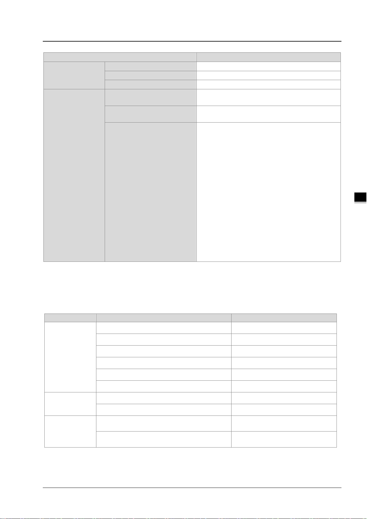
1.3.1 Delta EIP Architectu r e
This typical Delta EI P arc hit ecture in cludes EI P Scanner and Adapter; data mapping can be achieved between d evice s via
an I/O connection and explicit message.
The AHCPU5X1-EN series which includes AHCPU501-EN, AHCPU511-EN, AHCPU521-EN and AHCPU531-EN
support Ethernet single port communication and for network installation, it is required to employ EtherNet/IP
devices.
The AHCPU560-EN2, AH10EN-5A and AHRTU-ETHN-5A series support Ethernet dual port and DLR function; thus
it can install, configure, and maintain linear as well as device-level ring (DLR) networks by using EtherNet/IP
devices with embedded switch technology.
1-3
Page 10

EtherNet/IP Operation Manual
_1
1.3.2 Product Features
Flexibility
- Flexible topology: EIP devices may include an Ethernet single port as well as Ethernet dual port, and provide
applicable networks such as linear topology, ring topology and ring topology for faster expansion and easier
management.
- EtherNet/IP works on a TCP/UDP/IP based Ethernet network, uses most widely deployed collections of
Ethernet standards and supports Wifi connection. Even for personnel with no IT background, the network can
still be built up easily.
- Applicable networks include linear topology, ring topology, star topology, Ethernet, EtherNet/IP, one or more
LANs, etc. Configuration can be set via a USB device or an interface.
Simplicity
- Via a connector: Delta provides a full range of product line, including human machine interfaces (HMI),
programmable logic controllers (PLC) and inverter drives, for application in an industri al operation. Simply via a
RJ-45 connector, a network can be built up, saving costs on cables and other connecting tools.
- Single network: In replace with the 3-tier industrial architecture, single network architecture provides 100Mbps
high-speed cyclical and non-cyclical data mapping function, ensuring a complete network diagnosis and
effectively shortening debugging time.
- Graphical user interface designed software: The EIP Builder is graphical user interface designed for intuitive
operation.
Integration
- Data mapping: The EIP Builder provides a consistent setting interface, allowing users to reduce the time to
learn and set up configurations easily.
- Listed device parameters: The EIP Builder presents a parameter list of Delta devices. Instead of looking up in
the user manual, users can quickly check on the para meters from the list.
- EDS file: Users can connect to Delta and other brand EtherNet/IP products via the EDS files.
1-4
Page 11

2
Chapter 2. Network Installation
Table of Contents
2.1 EtherNet/IP Device ......................................................................................... 2-2
2.2 Network Installation ........................................................................................ 2-2
2.2.1 Single Port Device ..…………………………………………………………………….………………………………2-2
2.2.2 Dual Port Device …………………………………………………………………………………………………..…….2-3
2.2.3 PC Software ..…………………………………………………………………………………………………………….…2-4
2-1
Page 12

EtherNet/IP Operation Manual
_2
2.1 EtherNet/IP Device
A Delta EtherNet/IP (EIP) device allows users to build a linear topology, ring topology, and star topology. A
Delta EIP device includes the EIP Builder software, EIP Scanner, EIP Adapter, EIP Tap, and Ethernet switch.
EIP Scanner and EIP Adapter, each of them can be further divided to a single port and dual port.
Ethernet single port: the AHCPU5X1-EN series including AHCPU501-EN, AHCPU511-EN,
AHCPU521-EN and AHCPU531-EN.
Ethernet dual port: the AHCPU560-EN2, AH10EN-5A and AHRTU-ETHN-5A series
2.2 Network Installation
Each EtherNet/IP device is connected to an Ethernet switch via a CAT 5e cable. Please use Delta standard
cables and the DVS series industrial switches. Refer to Delta PLC/HMI Cable Selection Guide for more
information.
2.2.1 Single Port Device
A single port device can build up a linear and a star topology. An Ethernet switch is required to create a star
topology and a ring topology, and additionally an EtherNet/IP Tap is also needed.
Linear Topology
Linear Topology 1
Linear Topology 2
2-2
Page 13

Chapter 2 Network Installation
2_
Star Topology
2.2.2 Dual Port Device
A dual port device can build up a linear, star and ring topology. A DLR function is required to create a ring
topology. Refer to section 9.2 for DLR supported series.
Linear Topology
Star Topology
Ring Topology
A DLR function is required to create a ring topology. Refer to section 9.2 for DLR supported series.
2-3
Page 14

EtherNet/IP Operation Manual
_2
When a switch is needed for topology , the switch should support the DLR function. If not, the connection might
fail.
2.2.3 PC Software
Linear and star topology
Install the EIP Builder on your PC to monitor and configure the EIP devices. Users can also connect an EIP
device to their PCs directly or use a switch to connect to the PCs.
2-4
Page 15

Chapter 2 Network Installation
2_
Ring topology
Install the EIP Builder on your PC to monitor and configure the EIP devices. Be sure to save a network
connection for your PC to connect to the EIP device.
Or you can use an EIP tap to connect your PC so that the ring topology can stay intact.
2-5
Page 16

EtherNet/IP Operation Manual
_2
MEMO
2-6
Page 17

3
Chapter 3 Product Specifications
Table of Contents
3.1 Ethernet Specifications ............................................................................... 3-2
3.1.1 AHCPU5x1-EN/ AHCPU560-EN2 ................................................................... 3-2
3.1.2 AH10EN-5A ............................................................................................... 3-2
3.1.3 AHRTU-ETHN-5A ........................................................................................ 3-2
3.2 Ethernet/IP Specifications ......................................................................... 3-3
3.2.1 AHCPU5x1-EN/ AHCPU560-EN2 ................................................................... 3-3
3.2.2 AH10EN-5A ............................................................................................... 3-4
3.2.3 AHRTU-ETHN-5A ........................................................................................ 3-4
3.2.4 Maximum Transmission Speed of Delta Products ............................................ 3-5
3.2.5 Calculating CIP Connection.......................................................................... 3-6
3-1
Page 18

EtherNet/IP Operation Manual
_3
Communication Protocols
EtherNet/IP, MODBUS TCP
Protocols
Communication Speed
10/100 Mbps Auto-Detection
Communication Interface
RJ-45 with Auto MDI/MDIX
Communication Protocols
EtherNet/IP, MODBUS TCP
Protocols
BOOTP, DHCP, SMTP, SNMP, NTP
Communication Speed
10/100 Mbps Auto-Detection
Communication Interface
RJ-45 with Auto MDI/MDIX
Communication Port
Communication Protocols
EtherNet/IP, MODBUS TCP
Protocols
BOOTP, DHCP, NTP
Communication Speed
10/100 Mbps Auto-Detection
Communication Interface
RJ-45 with Auto MDI/MDIX
Communication Port
3.1 Ethernet Specifications
3.1.1 AHCPU5x1-EN/ AHCPU560-EN2
BOOTP, DHCP, SNMP, NTP
Numbers of the Ethernet
Communication Port
AHCPU5x1-EN:1
AHCPU560-EN2:2
3.1.2 AH10EN-5A
Numbers of the Ethernet
2
3.1.3 AHRTU-ETHN-5A
Numbers of the Ethernet
2
3-2
Page 19

3_
3.2 Ethernet/IP Specifications
Item
Specification
Category
Scanner / Adapter
Topology
Star
Requested Packet Interval (RPI)
1 ms~1000 ms
Max. Transmission Speed
10000 pps
Max. Data Length
500 bytes
servers from the UCMM type (for V2.1 or later version)
servers from the Class 3 (for V2.1 or later version)
Identity Object (16#01)
Ethernet Link Object (16#F6)
Connections
Max. Data Length
500 bytes
Requested Packet Interval (RPI)
1 ms~1000 ms
Connections
Max. Data Length
500 bytes
3.2.1 AHCPU5x1-EN/ AHCPU560-EN2
General
Max. Number of the CIP
Connections
Chapter 3 Product Specifications
AHCPU501-EN: 32 (Clients + Servers)
AHCPU511-EN: 64 (Clients + Servers)
AHCPU521-EN: 128 (Clients + Servers)
AHCPU531-EN: 256 (Clients + Servers)
AHCPU560-EN2: 256 (Clients + Servers)
CIP Network
I/O Connection
CIP Network
Explicit Message
CIP Network
Produced Tag
Max. Number of the TCP
Connections
Class 3 (Connected Type)
UCMM (Non-Connected Type)
CIP Objects
Max. Number of the CIP
AHCPU501-EN: 16 (Clients + Servers)
AHCPU511-EN: 32 (Clients + Servers)
AHCPU521-EN: 64 (Clients + Servers)
AHCPU531-EN: 128 (Clients + Servers)
AHCPU560-EN2: 128 (Clients + Servers)
Total 32 (Clients + Servers), in clud ing the cl ient s +
Total 32 (Clients + Servers) , including the clients +
Message Router Object (16#02)
Assembly Object (16#04)
Connection Manager Object (16#06)
Port Object (16#F4)
TCP/IP Interface Object (16#F5)
32 (Clients + Servers) (for V2.1 or later version)
Max. Number of the CIP
CIP Network
Consumed Tag
Requested Packet Interval (RPI) 1 ms~1000ms
32 (Clients + Servers) (for V2.1 or later version)
3-3
Page 20

EtherNet/IP Operation Manual
_3
Item
Specification
Category
Scanner /Adapter
Topology
Connections
Requested Packet Interval (RPI)
1 ms~1000 ms
Max. Transmission Speed
6400 pps
Max. Data Length
500 bytes
servers from the UCMM type
servers from the Class 3
Identity Object(16#01)
Item
Specification
Category
Adapter
Topology
Connections
3.2.2 AH10EN-5A
General
CIP Network
I/O Connection
CIP Network
Explicit Message
Max. Number of the CIP
Max. Number of the TCP
Connections
Class 3 (Connected Type)
UCMM (Non-Connected Type)
CIP Objects
Star, Linear, Ring
64 (Clients + Servers)
64 (Clients + Servers)
Total 32 (Clients + Servers), including the cl ients +
Total 32 (Clients + Servers), including the cl ients +
Message Router Object(16#02)
Assembly Object(16#04)
Connection Manager Object(16#06)
DLR Object(16#47)
QoS Object(16#48)
Port Object(16#F4)
TCP/IP Interface Object(16#F5)
Ethernet Link Object(16#F6)
Vendor specific object:
X Register(16#350)
Y Register(16#351)
D Register(16#352)
M Register(16#353)
S Register(16#354)
T Register(16#355)
C Register(16#356)
HC Register(16#357)
SM Register(16#358)
SR Register(16#359)
Control Register(16#370)
Input Register(16#371)
Output Register(16#372)
3.2.3 AHRTU-ETHN-5A
General
CIP Network
I/O Connection
3-4
Max. Number of the CIP
Max. Number of the TCP
Connections
Star, Linear, Ring
96
48
Page 21
Chapter 3 Product Specifications
3_
Item
Specification
Requested Packet Interval (RPI)
1 ms~1000 ms
Max. Transmission Speed
10000 pps
Max. Data Length
500 bytes
servers from the UCMM type
servers from the Class 3
Category
Product
Max. Transmission Spe e d (pps)
VFD-MS300 Series
(CMM-EIP01 communication card)
VFD-C2000 Series
CIP Network
Explicit Message
Class 3 (Connected Type)
UCMM (Non-Connected Type)
CIP Objects
Total 48 (Clients + Servers), including the cl ient s +
Total 48 (Clients + Servers) , including the clients +
Identity Object(16#01)
Message Router Object(16#02)
Assembly Object(16#04)
Connection Manager Object(16#06)
DLR Object(16#47)
QoS Object(16#48)
Port Object(16#F4)
TCP/IP Interface Object(16#F5)
Ethernet Link Object(16#F6)
Vendor specification object:
Status Register(16#370)
Input Register(16#371)
RTU AI Register(16#373)
RTU AO Register(16#374)
RTU DI Register(16#375)
RTU DO Register(16#376)
3.2.4 Maximum Transmission Speed of Delta Products
The EtherNet/IP transmission speed is expressed in terms of packets per second (pps). In addition, the actual
transmission speed is affected by the requested packet interval (RPI) and the scan time of the CPU as an EIP
scanner. Below is a list regarding the maximum transmission speed of Delta EIP products for your reference.
AHCPU5X1-EN Series, AHCPU560-EN2 10,000
AH10EN-5A 6,400
Mid-range PLC
Small PLC
AC Motor Drive
AHRTU-ETHN-5A 10,000
AH10EMC-5A 6,400
AS300 Series, AS200 Seri es 3,000
AS-FEN02 communic ati on c ard 10,000
DVPES2-E Series 16,00
DVP26SE 1,600
800
(CMC-EIP01 communication card)
800
3-5
Page 22

EtherNet/IP Operation Manual
_3
Method to Calculate CIP Connection
Adapter
Scanner
Limited to AHCPU and third-party host
2) Each AIO or NIO module uses 1 connection
Do not support
AH10EN-5A
Each data exchange group uses 1 connection
AHCPU560-EN2
1) If using A S series or a thir d -party as the host
uses 1 connection
Do not support
AS200
DVPES2-E
Each data exchange group uses 1 connection
Do not support
DVP26SE
Each data exchange group uses 1 connection
Do not support
CMC-EIP01
Each VFD uses 1 connection
Do not support
CMM-EIP01
Each VFD uses 1 connection
Do not support
3.2.5 Calculating CIP Connection
Users can refer to the EIP Builder data exchange page (see below) to find out the number of CIP and TCP
connections. The method for calculating the number of CIP connection is also listed below. .
Series Model
AHRTU-ETHN-5A
AH
AHCPU5x1-EN
AS-FEN02
AS
AS300
DVP
VFD
1) RTU + DIO uses 1 connection
1) Each data exchange group uses 1 connection
2) Execute instruction API2208 EIPRW uses 1 connection
CPU, RTU + DIO + AIO use 1 connection
2) If using AH ser ies as the host CPU, RTU +
DIO use 1 connection, each AIO module
1) Each data exchange group uses 1 connection
2) Execute instruction API2208 EIPRW uses 1 connection
3-6
Page 23
Chapter 3 Product Specifications
3_
Long Range Communication
Station A
( AHRTU-ETHN -5A)
Module
Configuration:
AH16AM10N-5A X2
AH16AN01T-5A X2
AH06XA-5A X 3
AH10SCM-5A X 2
Long Range Communication
Station B
Module
Configuration :
AH16AM10N-5A X2
AH16AP11T-5A X 4
AH08DA-5A X 2
AH08AD-5A X 1
AS Series Host
CIP Connection Used
for Data Exchange: 5
AH Series Host
( Scanner )
Calculating CIP Connections:
1. Long Range Communica tio n Station A: 1 ( RTU+DIO)+ 3 ( AI /O)+ 2 (SCM)=6
2. Lon g Ran ge Communication Sta tion B: 1 RTU DIO 3 ( AI/O) = 4 ( + )+
3. AS Series Host: 5 (Connection Used f or Data Exchange)
=> Total of CIP C onnection U sed: 6+4 5 15= =
( AHRTU-ETHN-5A)
※ AH Series Host – Example of Calculating the number of CIP Connection:
3-7
Page 24

EtherNet/IP Operation Manual
_3
MEMO
3-8
Page 25

4
Chapter 4 EIP Builder
Table of Contents
4.1 Access EIP Builder ...................................................................................... 4-2
4.1.1 Setting Up EIP Scanner .............................................................................. 4-2
4.2 Set up the IP Address ................................................................................. 4-4
4.2.1 IP Address Types ....................................................................................... 4-4
4.2.2 Set up the IP Address (Static IP) ................................................................. 4-5
4.2.3 Set up the IP Address (BOOTP/DHCP) .......................................................... 4-6
4.2.4 IP Modification (BOOTP/DHCP) .................................................................. 4-11
4.3 Network ................................................................................................... 4-13
4.4 Data Mapping ........................................................................................... 4-23
4.5 Diagnosis ...................................................................................................4-28
4.6 AH Series – Connect to a RTU module ........................................................4-30
4.6.1 AHCPU5x1-EN Series/AHCPU560-EN2 ......................................................... 4-30
4-1
Page 26
EtherNet/IP Operation Manual
_4
Open
ISPSoft V3 0.
Create
ISPSoft Project
Open
HWCONFIG
Download
HWCONFIG
Create
EIP Module
Y
EIP
PLC
Open
EIP Builder
Start
N
Delta EtherNet/IP software, EIP Builder, is embedded in the ISPSoft. It can be called or run independently
through the ISPSoft software (applicable with version 3.06 and later versions).
4.1 Access EIP Builder
The EIP Builder can be ca lled from Delta EIP Scanner’s HW CONFIG in the ISPSoft. It can also be called
independently to set up parameters for the Adapter. Delta EIP Scanner is equipped with the EtherNet/IP
communication PLC and the EtherNet/IP module. Refer to chapter 9.3 for a list of Delta EIP Scanner products
supported by the EIP Builder.
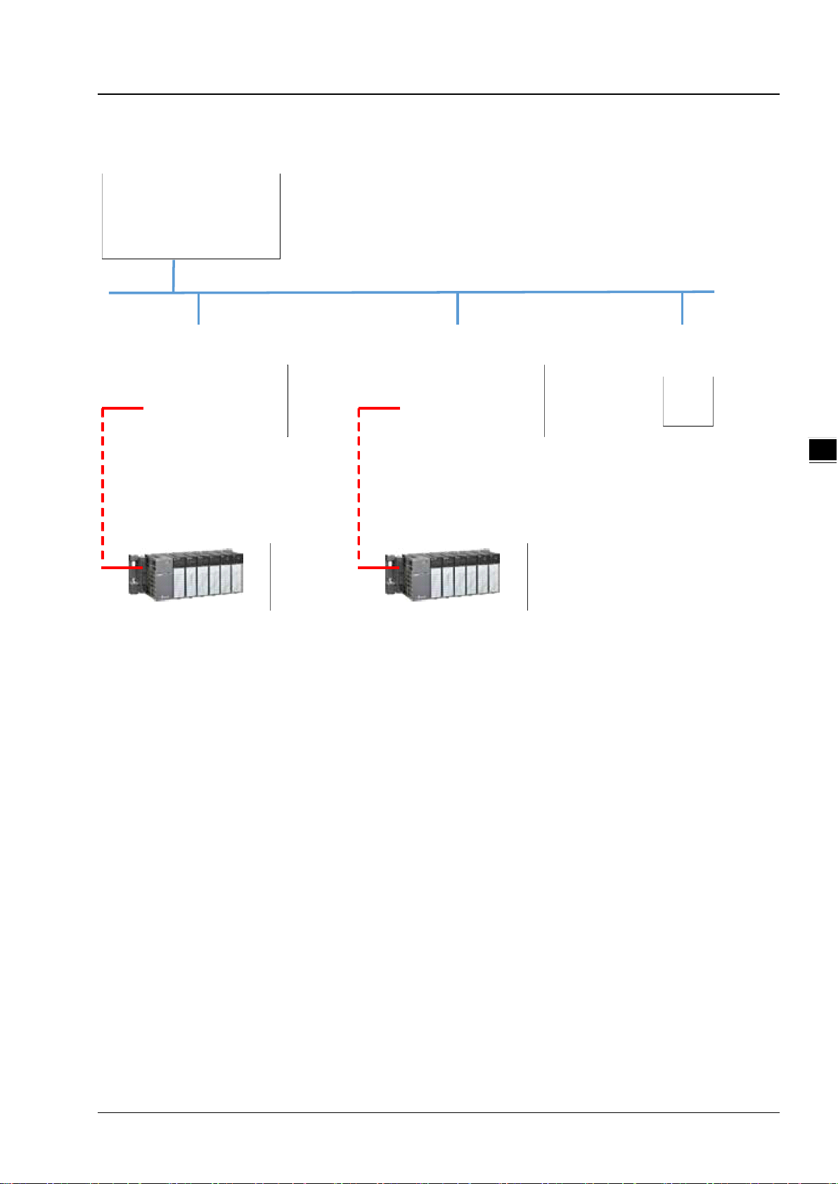
4.1.1 Setting Up EIP Scanner
Running Process
Run the EIP Builder via an EIP Sc an ner ( s ee be lo w). When using a Delta EIP Scanner, users need to set up
an EIP module through the HWCONFIG in the ISPSoft.
Operation Steps
1. Open ISPSoft : Find ISPSoft 3.06 from the start menu in Windows. Click the start menu and go to All
programs > Delta Industrial Automation > ISPSoft 3.06
4-2
Page 27

Chapter 4 EIP Builder
4_
2. Create a new project: Click File > New and you will see the Create a New Project window.
3. Select a PLC: Select a PLC product that supports the EIP builder in the Create a New Project window.
4. Open the HWCONFIG: Double click the HWCONFIG option under the Project.
5. Create an EIP module (AH10EN-5A):
Select the AH10EN-5A from the Network Module in the Product List.
Drag the selected AH10EN-5A to the CPU’s main backplane.
4-3
Page 28

EtherNet/IP Operation Manual
_4
Type of IP Address
Definition
for a network in which each host has a permanent network connection.
gateway, main computer name and the WINS server automatically.
6. Save and download the HWCONFIG:Click Save to save the HWCONFIG settings and then click
Download to PLC to download the file to PLC.
7. Open the EIP Builder:
7.1 Right-click the AH10EN-5A on the CPU’s main backplane and you will see the EIP Builder. Double
click it to open the EIP Builder.
7.2 Right-click the AHCPU5x1-EN on the CPU’s main backplane and you will see the EIP Builder.
Double click it to open the EIP Builder.
4.2 Set up the IP Address
This section will provide an overview of how to set up the IP address for AH10EN-5A IP and
AHCPU5x1-EN/AHCPU560-EN2. The IP address should be set up before configuring EIP related parameters
or data mapping settings.
4.2.1 IP Address Types
The AH10EN-5A series and AHCPU5x1-EN/AHCPU560-EN2 series supports 3 types of IP addressing,
BOOTP, DHCP and static IP address.
Via the TCP/IP Bootstrap Protocol (BOOTP) to set up the IP address, netmask and
BOOTP
DHCP
4-4
gateway. BOOTP server may require some configuration. The Bootp protocol is designed
Via the Dynamic Host Configuration Protocol (DHCP) to obtain IP address, netmask,
Page 29
Chapter 4 EIP Builder
4_
Create
ProjectISPSoft
Open
HWCONFIG
Set up
IP Address
Create
EIP M odule
Y EIP
PLC
N
Download
HWCONFIG
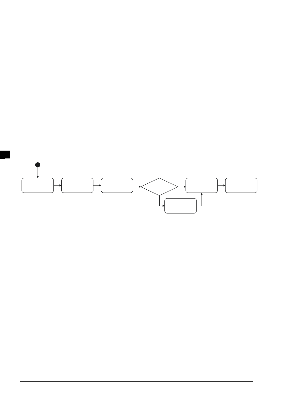
4.2.2 Set up the IP Address (Static IP)
Operation Steps:
When using an EIP product with a static IP address, users need to set up the IP address through the
HWCONFIG in the ISPSoft.
Refer to section 4.1.1 for how to set up an EIP module through the HWCONFIG in the ISPSoft.
1. Configure the network parameters
1.1 AH10EN-5A
Double-click the AH10EN-5A in the HWCONFIG to open the Parameter Setting page.
Set up the IP address under the Network Parameters node. Once the setup is done, click OK to leave
this page.
4-5
Page 30

EtherNet/IP Operation Manual
_4
Create
AddressMAC
Set up IP
Same I assign P
mode after e ach
power-on
Reset I assign P
mode after e ach
power-on
Y
Disable
BOOTP
N
Open
EIP Builder
Open
IP M anager
1.2 AHCPU5x1-EN
Double-click the AHCPU5x1-EN in the HWCONFIG to open the Parameter Setting page.
Set up the IP address under the Ethernet Basic tab. Once the setup is done, click OK to leave this page.
Save and download the HWCONFIG: Click Save to save the HWCONFIG settings and then click
Download.
4.2.3 Set up the IP Address (BOOTP/DHCP)
Operation Steps:
When using an EIP product with a BOOTP/DHCP IP address, users can set up the IP address through
the IP Manager in the EIP Builde
r.
4-6
Page 31

4_
Descriptions for the IP Manager:
1
2
3
4
7
6
8
9
10
5
Item
Definition
from the BOOTP/DHCP server.
name.
Clear List
Clear all the contents on the list.
New
Add new IP/MAC address.
Export
Export the IP/MAC address list; the file format is .CSV.
Enable BOOTP
Enable the BOOTP to assign an IP address for the selected item.
Enable DHCP
Enable the DHCP to assign an IP address for the selected item.
will not request for IP
addresses from the server.
Chapter 4 EIP Builder
Stop the Server
Network Settings
Delete Delete the selected item on the list.
Import Import the IP/MAC address list; the file format is .CSV.
Disable BOOTP/DHCP
Stop the BOOTP/DHCP server; the IP manager will not request for IP addresses
Set up the subnet mask, gateway, primary DNS, secondary DNS, and domain
Disable the BOOTP/DHCP on the device; the device
Operation Steps:
1. MAC address: find the MAC address on the EIP device as its unique identity.
4-7
Page 32

EtherNet/IP Operation Manual
_4
2. Open the IP Manager
Click the Tool tab of the EIP Builder and click to open the IP Manager setup page.
The IP Manager can be the BOOTP/DHCP Server, receiving IP address requests from devices.
4-8
Page 33

4_
3. Set up the IP address
Select and double-click the listed address to open the IP setup page.
Chapter 4 EIP Builder
Type the IP address.
4. Disable DHCP/BOOTP
Click to select the device in the Mapping Table that you’d like to disable its DHCP/BOOTP function and
then click the Disable DHCP/BOOTP button. After that the selected device will not send DHCP/BOOTP
requests. For the modification on the IP address receiving mode, refer to section 4.2.4 for more
information.
4-9
Page 34

EtherNet/IP Operation Manual
_4
Note
1. Enable BOOTP: When the IP address receiving mode is in BOOTP (BOOTP is enabled), the IP
address is assigned, and the device will send out BOOTP requests for IP addresses during each
power-on.
2. Enable DHCP: When the IP address receiving mode is in DHCP (DHCP is enabled), the IP address
is assigned, and the device will send out DHCP requests for IP addresses during each power-on.
3. Disable DHCP/BOOTP: When the IP address receiving mode is in BOOTP (BOOTP is enabled), the
IP address is assigned; once the Disable DHCP/BOOTP button is clicked, the device will not send
out DHCP/BOOTP requests for IP addresses during each power-on.
4-10
Page 35

Chapter 4 EIP Builder
4_
Open
HWCONFIG
Setup
parameters
Setup IP
receiving mode
Open
EIP Builder
Download
HWCONFIG
Open
IP Manager
4.2.4 IP Modification (BOOTP/DHCP)
To enable the DHCP or BOOTP function again, users will need to use the device software to make that
change. Take the AH10EN-5A series as an example, you will need to go to ISPSoft > HWCONFIG > IP
Manager. Open the IP Manager and set up the IP address receiving mode.
Operation Steps:
1. Refer to section 4.1.1 for how to open the HWCONFIG.
2. Set up the parameters: Enable the IP address receiving mode to BOOTP/DHCP.
2.1 AH10EN-5A
◆ Double-click the device you’d like to change its IP address receiving mode.
◆ You will see the option Network Parameters. Click this option to see the Network Parameters setup
page.
◆ Make changes on the items that you’d like to change their IP address receiving modes and click OK to
confirm the settings.
4-11
Page 36

EtherNet/IP Operation Manual
_4
2.1 AHCPU5x1-EN
◆ Double-click the device you’d like to change its IP address receiving mode.
◆ Set up the IP address under the Ethernet Basic tab.
◆ Make changes on the items that you’d like to change their IP address receiving modes and click OK to
confirm the settings.
3. Download the HWCONFIG
◆ Refer to section 4.1.1 for the related information.
4. Open the EIP Builder
◆ Refer to section 4.1.1 for the related information.
5. Open the IP Manager
◆ Refer to section 4.2.2 for the related information.
6. Open the IP setup page
◆ Refer to section 4.2.2 for the related information.
4-12
Page 37

Chapter 4 EIP Builder
4_
Add Device
(Scan Network)
Create Network
(Set u p Connection)
Set up Device
Settings
IP Manager
(Set up IP)
Add Devices
(Manually)
EIPBuilder
1
3
2
4
Item
Definition
Toolbar
Toolbar buttons
Network View
Display the connected devices and their connection status
Configuration Area
Set the parameters and display the configur ati on s
Product List
Display the available devices to be connected to EtherNet/IP
4.3 Network
The EIP Builder provides a graphical user interface; users can see the devices and their EtherNet/IP
connections in the Network View. This section will provide an over v iew of how to add your devices in and
build up the network connections. The procedure of the process is stated below.
Descriptions for the EIP Builder:
4-13
Page 38

EtherNet/IP Operation Manual
_4
Scanner
1
2
3
4
Device Name
Name for the device
The last digit of the IP address will be shown on the COM port.
network.
Toolbar
Icon Name Definition
New Create a new EIP Builder project
Open Open an existing project
Save Save the project
Scan Network Scan the network for device availability
Check Check if the project is planed nicely
On-line Mode Switch to on-line mode
Uploader Upload
Downloader Download
Setup Button
Open the communication setting; set up the path connecting the PC to the EIP
Network View
Station Name Name for the station
Ethernet COM Port
Name Definition
Display the number of devices with Ethernet communication ports.
Network_0
Display connection status; devices on the same line indicate they are in the same
Configuration Area
Refer to section 4.3.3 for more information.
4-14
Page 39

4_
Product List
2
1
Name
Definition
the system.
1
3
2
Name
Definition
Selection checkboxes
Tick to select the devices you’d like to add to the network view
Refresh
Refresh to scan the network again
Join
Add the selected device to the network view
Chapter 4 EIP Builder
Se arch Bar
Product List
Scan Network
Type the module name t o s ear ch; when nothing found, that m eans th er e is n o E DS file in
Categorize the devices according to the definition of the EtherNet/IP; for devices from
rd
the 3
party will be put in the Others folder.
4-15
Page 40

EtherNet/IP Operation Manual
_4
(a)
(b)
(c)
Operation Steps:
1. Add new devices in (scan the network): Click the setup button to bring out the communication
set up page.
Once your PC is connected to the EIP Scanner, there are 3 ways to set up the network
communication.
(a) Select the created Driver: Select the created driver from the COMMGR Driver drop down list.
(b) Edit the created Driver: Click the setup button in the Common Setting section to bring out the
Driver Properties to edit.
(c) Add a new Driver: Click the setup button+ in the Common Setting section to bring out the
Driver Properties to add new Driver.
4-16
Page 41

Chapter 4 EIP Builder
4_
Driver Properties
Click the Scan Network button, the EIP Builder will scan the network and list the scanned devices in
the Device List.
4-17
Page 42

EtherNet/IP Operation Manual
_4
Tick to select the devices you’d like to add to the Network. After that, click Join to add the selected
devices.
2. Add devices (Manually) : Select the devices you’d like to add from the Device List; you can also type in
the module name in the search bar. After that drag the device you’d like to add to the network view.
3. Create Network
Drag the Ethernet communication port of the device to the network to create connection.
4-18
Page 43

4_
Create network connections for the devices.
Chapter 4 EIP Builder
Once the connection is established, click the network line “Network_0”, you will see all the
connected devices in this network.
4-19
Page 44

EtherNet/IP Operation Manual
_4
4. Set up the parameters
Click tabs of the Information, EIP parameter and the EDS Parameter to see and edit the parameters
respectively.
(a) Information Tab
This tab contains information regarding Module Name, Version, Rack, Slot, Slot, IP address, Mask,
Network and Data mapping Setting.
(b) EIP Parameter Tab
This tab contains information regarding parameters in the EDS file. When Off-line, users can only check
the connection parameters for setting up the EDS filtering rules.
Disable Keying: Disable checking on the product information and its versions.
Compatible Keyi ng: Checking if the product information and its master version are matched;
as for the minor version, check for its compatibility.
Exact Match: Checking if the product information, its master version and minor version are
matched.
While the device is connected, you can click the upload button to upload the related parameters back to the
device.
4-20
Page 45

Chapter 4 EIP Builder
4_
Name
Definition
Fault, Internal State, Configuration Status, and Module Identity.
Compatible Keying, and Exact Match.
Hardware Fault.
Status, Ring Supervisor, and Active Supervisor Precedence.
(c) Identification: Display information regarding Vendor, Product
①
Module Status
②
IP Setting
③
Connection
④
Port Status
⑤
Device Level Ring (DLR)
Type, Product Name, Revision, etc.
(d) Status: Display connection status, including Major Fault, Minor
Port1: Indicating port 1 of the device, for editing configurations
of the IP Address, Subnet Mask, Gateway Address, and Host
Name.
Remark: When there is a Port2, that means there are 2 Ethernet
communication ports.
EDS parameters filtering rules include Disable Keying,
Display Link Status, Speed, Duplex, Negotiation Status and
Display DLR information includes Network Topology, Network
4-21
Page 46

EtherNet/IP Operation Manual
_4
(c) EDS Parameter Tab: this is not supported on the AH10EN-5A series.
4-22
Page 47

Chapter 4 EIP Builder
4_
Download
Data Exchange
Data Exchange
Set up
Data Exchange
Table
Network View
1
2
3
4
7
6
8 9
5
10
Name
Definition
number is 64.
Enable
Enable / Disable the data mapping function
beforehand
to select the device’s IP address to add and edit the connection.
how to change the device name.
CPU Address
Start address of the data mapping’s register
modules)
page.
If TAG is selec ted
Consumed TAG can be selected from the drop-down list
Adapter Address/Parameter
Target adapter’s register address / parameters
is the same as TAG in .
4.4 Data Mapping
When the connection between devices is established, users can use the data mapping function to exchange
data between devices. This section will provide an overview of how to create a data mapping table.
Descriptions for the Data Mapping:
Connection Count
TAG
Data mapping connection count; each row represents one
independent EtherNet/IP connection. The number of connections
cannot exceed the maximum connection number that the Scanner
supports. For the AH10EN-5A series, the maximum connection
Use TAGs created to execute data mapping; after selected, this
function is enabled and
read only ()
registers are not available for the row selected
the leghth cannot be modified
comsumed TAG should be created in ISPSoft global symbols
IP Address
Adapter Name
Scanner’s register address +
address offset (EtherNet/IP
If TAG is selected
I/O Mapping Table
The IP address of the Adapter that you’d like to connect to. After the
data mapping connection is established, the system will load the
connected device’s IP address. Users can also use the drop down list
Once the IP address is selected, its name will be displayed but cannot
be modified here. Refer to section 4.3 for more information on
Actual represented register = starting register address + address
offset; starting register address can be set on the HWCONFIG setup
Input the Produced TAG of the EIP to be connected; the default name
Set up the IN/OUT parameters; when there is no I/O representative
table presented for the Adapter, they cannot be opened, for example
some PLCs.
4-23
Page 48

EtherNet/IP Operation Manual
_4
Name
Definition
Length
Set up the data mapping length; unit: byte, the maximum is 500 byte.
Property
Set up the advanced data mapping parameters.
Name
Definition
might have different mapping parameters.
Name to open the mapping table to edit.
Name to open the mapping table to edit.
mapping table to edit.
written to the Adapter.
1
2
3
4
I/O Mapping Table
Delta EIP devices provide I/O mapping table. If needed, users can use the table to edit the parameters.
Connection
In
Out
Select the connection from the drop down list. Different connection
Input the mapping parameters. The column No. states the maximum
number of mapping parameters to input. Double-cli ck the col umn
Output the mapping param eters. The column No. states t he maximum
number of mapping parameters to output. Double-click the column
Name
Value
Property
The parameter name; double-click the column Name to open the
Values; after editing and downloading the values will be stored in the
Scanner. When the connection is established, the values will be
4-24
Page 49

Chapter 4 EIP Builder
4_
Name
Definition
exchange data at regular time intervals, unit: ms
Multicast
Communication mode setup: M ult icast or Point-to-Point
multiple of RPI (RPI*X).
Application: renew data according to the product setup
Data Mapping Tab
Network_0 Data Mapping Table
Requested Packet Interval (RPI)
Timeout
Trigger Mode
RPI setup: via the I/O connection to connect to EtherNet/IP to
Timeout setup; set up the timeout time according to the RPI or the
Trigger Mode: Cyclic, Change of State, and Application
Cyclic: renew data cyclically
Change of State: renew data once there is any change
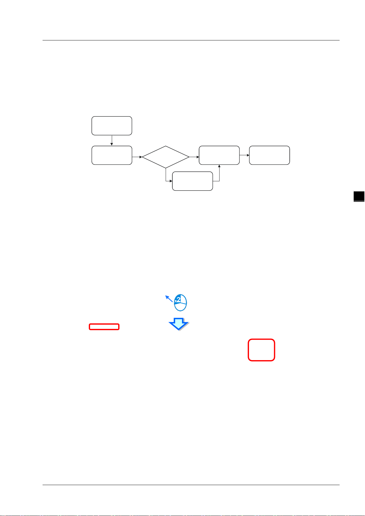
Operation Steps:
1. Create a data mapping table (※):
Click to select the Scanner Ethernet COM port that you’d like to perform the data mapping and then
right-click to see the options. Click Data Exchange to open the Data Mapping Table.
After the selection is made, the system will create a Data Mapping Tab, shown as Network_0.
4-25
Page 50

EtherNet/IP Operation Manual
_4
2. Set up the Data Mappi ng Par ameters
Type the parameters in the data mapping table
a) See the example of reading the D500~D599 of the Adapter with the IP address 192.168.1.2 to
the D10000~D10099 of the Scanner below.
b) See the example of writing the D20200~D20299 of the Scanner to the D100~D199 of the
Adapter with the IP address 192.168.1.1
Use TAG in data mapping
a) Add a General Device in the network and select the IP address of the Produced TAG of the
device to be connected. For adding devices in the network, please refer to section 4.3 for more
information.
4-26
b) The data mapping page
Page 51

Chapter 4 EIP Builder
4_
c) Select TAG to have this function enabled. And after this function is enabled, the attributes is
read only ().
※ Users can also select TAG and then input the IP address directly to connect to TAGs from other
devices. In this case, there is no need to create a connection to Gerneal Device.
d) Users can use the drop-down list of the CPU Address /TAG to select the already created
Consumed TAG.
After the TAG function is selected, the system will input data in the columns of Adapter register
e)
address, parameter, and address of the TAG with the same name. Users can also edit the data
in the columns. Make sure the TAG name is the same as the Produced TAG of the EIP to be
connected
.
Set up property
a) Click the Property to set up.
b) Type the data mapping parameters
Set the Requested Packet Interval (RPI) to renew the data between the Scanner and Adapter
cyclically, for example every 20ms.
4-27
Page 52

EtherNet/IP Operation Manual
_4
Data Mapping Tab
Network View
3. Download
Click Downloader on the tool bar to open the download window.
Selecting the Scanner communication port of the EIP Builder; every communication port can
download a data mapping table.
4.5 Diagnosis
The EIP Builder can provide the diagnosis on the connection and data mapping status. For the connection
status, refer to Adapter connection status and indicator in the Network View tab and for data mapping status
and error codes, refer to Network_0, the data mapping tab.
4-28
Page 53

4_
Operation Step
Status Indicator
Network View
1. Click the On-line Mode on the toolbar.
2. Network View (Connection Status):
a) Click the Network View tab to check the device status from the indicators, for example RUN /
STOP and Error indicators on the PLC.
Chapter 4 EIP Builder
b) The dotted line and the warning sign indicate connection error, as the image shown below.
Network_0 (Data Mapping):
a) Click the On-line Mode on the toolbar.
4-29
Page 54

EtherNet/IP Operation Manual
_4
Open
ISPSoft
Delta
EIP
Scanner
Y
Open
EIP Builder
N
HWCONFIG
Setups
EIPBuilder
RTU
HWCONFIG
Download
RTU
HWCONFIG
Software
…
Download
to AHRTU
Import
EDS file
b) Click the Network _0 to check the data mapping status and the error codes. For error code
definition, refer to section 6.2.
4.6 AH Series – Connect to a RTU module
This section will provide an overview of how to connect the Delta AH series EtherNet/IP RTU modules such
as AHRTU-ETHN-5A to Delta EIP Scanner and EIP Scanner from other brands. Seet the operation steps
.
below
4.6.1 AHCPU5x1-EN Series/AHCPU560-EN2
AHCPU5x1-EN series with f irm ware vers ion lat er than V2.0 0 and AHCPU560-EN2 supports EtherNet/IP.
Users can connect to Delta AHRTU-ETHN-5A modules via EtherNet/IP. Once the settings are done, users
can use the devices X, Y and D in AHCPU5x1-EN series and
I/O modules connected to AHRTU-ETHN-5A.
Running Process:
AHCPU560-EN2 to control digital and analog
Open EIP Builder and add the module AHRTU-ETHN-5A in the Network View. Open HWCONFIG to set up
digital and analog I/O modules of AHRTU-ETHN-5A.
4-30
Page 55

Chapter 4 EIP Builder
4_
Open
ISPSoft
Delta
EIP
Scanner
Y
HWCONFIG
Setups
EIPBuilder
RTU
HWCONFIG
Download
Operation Steps:
1. Refer to section 4.1 for more information on HWCONFIG in ISPSoft and EIO Builder.
EIP Builder
Add the module AHRTU-ETHN-5A in the Network View and create a connection to the CPU for data
mapping.
2. Double-click the AHRTU-ETHN-5A module to open HWCONFIG.
4-31
Page 56

EtherNet/IP Operation Manual
_4
Name
Description
1
Information: Rack 1
Information of the rack 1
2
Slot number
Slot number of rack 1 (power module and AHRTU module are excluded)
3
Label
Module Name
4
MDS Version
Device firmware version
5
Description
Device description
6
Input Device Range
The input devices assigned to a module are displayed here
7
Output Device Range
The output devices assigned to a module are displayed here
RPI setting value; unit: mm
according to the RPI time set for the AHRTU-ETHN-5A.
9
Multicast
Communication mode setup: M ult icast or Point-to-Point
Timeout setup; set up the timeout time according to the RPI or the
multiple of RPI (RPI*X).
11
Trigger mode
Renew data according to the set RPI time
12
Connection type
Owner or Listen only
R TU
HWCONFIG
Download
Set up
parameters
Add
I/O module
Descriptions for the EIP Builder:
8
10 Timeout
Requested Packet Interval
(RPI)
Operation Steps:
Only analog I/O modules and special modules need to set the RPI time
to renew data; for other digital I/O modules, data can be re ne wed
4-32
Page 57

4_
1. Add an I/O module
Chapter 4 EIP Builder
Add the I/O modules according to the real placement by dragging the modules on the left hand side to the
right side of the RTU module. Make sure the slot assignment is the same as the real placement.
2. Setting parameters
The sy stem automatically assigns devices to a module so that the data in the module can be stored.
The devices assigned to a module are displayed in the Input Device Range cell and the Output
Device Range cell.
Click the … in the “Input Device Range” and “Output Device Range” column to edit the ranges.
4-33
Page 58

EtherNet/IP Operation Manual
_4
RPI setting value; unit: mm
Only analog I/O modules and special modules (for example AH04AD-5A) need to set the RPI time to
renew data. For other digital I/O modules, data can be renewed according to the RPI time set for the
AHRTU-ETHN-5A and values in this column cannot be modified in Network_0 tab.
After the setup is done, the detailed connection information of the ARTU-ETHN-5A modules will be
added in the data mapping tale. Data in the table cannot be modified here.
Parameters for special modules can be seen in the RTU HWCONFIG. Double-click the module in
the Network View tab to open the RTU HWCONFIG and check the corresponding device address in
the Normal Exchange Area tab.
4-34
Page 59

Chapter 4 EIP Builder
4_
3. Download
Save: after the parameters are set, click the Save button to save the parameters.
A warning window will appear if the changed settings have not been saved.
Download: Click the download icon to download.
4-35
Page 60

EtherNet/IP Operation Manual
_4
Tick the Seclt All option or select the module one by one to download the data mapping table.
4-36
Page 61

5
Chapter 5 Programming
Table of Contents
5.1. DFB_EIP_EXP Fu nction Bl ock ........................................................................ 5-2
5.1.1 Parameters .................................................................................................... 5-2
5.2. TAG Function ................................................................................................. 5-7
5.2.1 Produced TAG ............................................................................................ 5-7
5.2.2 Consumed TAG .......................................................................................... 5-9
5-1
Page 62

EtherNet/I P Operation Manual
_5
All connections in EtherNet/IP can be divided into explicit messaging connections and implicit (or I/O) messaging
connections. Explicit messaging us es TCP/IP and r equest/response communic ations procedure or c l ient/serv er
connection, requiring that the memory location of the information to be sent to the client be defined in the instruction it self.
Implicit messaging uses UDP/IP and is when a server sends informa t ion from p re defined memory locations to a client at a
given interval, using a requested packet in terval (RPI) parameter to sp ecify t he rate a t which data updates.
5.1. DFB_EI P_EXP Function Block
See the DFB_EIP_EXP function block below. Refer to the section 9.8 for objects that are supported by AH10EN-5A. For
using slaves via the AH10EN-5A, refer to the slave manual for related information on Objects.
When the AH10EN-5A acts as sc anners for EtherNet/IP, users can use the func t ion blo ck DFB_EIP_EXP to read/write the
objects of the adapters. When the EIP builder uses Objects as its parameters, every Object has various parameters.
The parameter unit is Attribute and the read/write path is ClassInstanceAttribute.
5.1.1 Parameters
The meaning of each parameter in the function blocks are stated below.
Name Description Data Type
When the execution bi t turns from Of f to On, th e function blo ck will be
Execute (Execution B it)
BID (Backplane number) The backplane number of the scanner module: 1 WORD
SID (Slot number) The slot num ber of the scann er m odule:0-11 WORD
PID (Port number) Assigned Ethernet P ort for the scanner module WORD
IP1 (IP address 1)
IP2 (IP address 2)
executed and will send out an explicit message. When the operation is
complete, the Done bit will be On. While an error occurs, a n Error bit will
be On, and an error code will be shown in the ERRCode.
This param eter is used to as sign th e first t wo IP addresses of the
adapter for the assigned scanner to read/write.
Example: IP = 192.168.1.5, IP1 will be writt en as 16#C0A8.
This param eter is used to as sign th e last two IP addr esses of t he
adapter for the assigned scanner to read/write.
Example: IP = 192.168.1.5, IP2 will be written as 16#0105.
BOOL
WORD
WORD
5-2
Page 63

5_
Setups for the explicit message connection:
0: UCMM: do not crea te a CIP connection.
Chapter 5 Programming
Mode
SerCode (Serv ice Code)
ClassId (Class number)
InstId (In s tance number)
AttrId (Attribute number)
1: Connected then close conn; after the transmission is done, close the
connection.
2. Connected then keep conn; after t he transmission is done, keep the
connection.
EtherNet/IP standard service code is similar to the function code. The
service codes specify the actions going to take. Delta products support
the follo w ing service codes.
0x01 – read every At trib ute;
0x0E – read a single one Attribute;
0x05 – reset from th e adapter;
0x10 – writ e a single one Attribute
Attribute is the basics of the EtherNet/IP, used for identifying
configurable parameters (Class) within a device.
Attribute is the basics of the EtherNet/IP, used for identifying
configurable parameters (Instance) within a device.
Attribute is the basics of the EtherNet/IP, used for identifying
configurabl e parameters (Attribute) within a devi ce.
WORD
WORD
WORD
WORD
WORD
If the scanner wants to write a parameter data to the adapter, the
parameter type s hould be also wr itten i n. The uni t for this parameter is
Size (Parameter t ype)
Data (Starting value)
Don (Completion bit ) W hen the operation is complete, the Don bit will be On. BOOL
Error (Error bit )
ErrCode (Error code)
Value (Return Data)
byte. When the Size is 1, it means the parameter type is BYTE . When
the Size is 2, it means the parameter type is WORD. When the Size is 4,
it means the parameter type is DWORD.
If the scanner wants to write a parameter data to the adapter, the
paramet er to be written c an be typed or can use the st artin g r egist er
address. The scanner will send the values in the Data to the adapter.
The Data leng th is determi ned by the Size. The storing order of the
values in the Data wi ll be little-endian first and then big-endian. If
Data=D0, Size=4, the D0 little-endian will be stored fi rst and t hen the D0
big-endian, D1 l i ttle-endian and then D1 big-endian.
Whi le an error occurs, an Error bit will be On, and an error code will be
shown in the ERRCode.
Error codes (refer to the following table)
16#00 indicates a successful communicatio n.
After th e function blocks are executed successfully, the AH10EN-5A will
put the rea d value to the parameter assi gned registers, low by tes first
and the high bytes.
WORD
WORD
BOOL
WORD
WORD
5-3
Page 64

EtherNet/I P Operation Manual
_5
Errors
The meaning of each error code in the function blocks are stated below.
Error
Code
16#01
16#02
16#03 Invalid parameter value The typed value is not in the parameter service range.
16#04
16#05
16#07 Connection lost The messaging connection was lost.
16#08
16#09 Invalid attribute value Invalid attri bute data detec ted
16#0E Attribute not settable A request to modify a non-modifiable attrib ute was receiv ed.
Connection failure A connection related service fai led al ong the c onnection
Resource unavailable Resources needed for the objec t to perform the requested
Path segment error The p ath segment identif ier or t he segment synt ax was not
Path destination unknown The p ath is referencing an object cl ass, instance or structure
Service not supported The requested service was not implemented or was not
Error
Description
path.
service were unavailable
understood by the processing node.
element that is not known or is not contained in the
processing node.
defined f or this Object C l ass/Instance.
16#10
16#11 Reply data too large The data to be transmitted in the response buffer is large
16#13
16#14 Attribute not supported The attribute specified in the request is not supported
16#15 Too much data The service supplied more data than was expected
16#16 Object do es not exist The object specified does not exist in the device.
Example 1: using UCMM to read the m anufac turer code of the IP address 192.168.1.10
Manufacturer code: ClassId=1, InstId=1, AttrId=1
The parameters in the function blocks are as below:
BID 16#01 Backplane 1
SID 16#01 Slot 1
Device state conflict The device’s current mode/state prohibits the execution of
the requested ser vice.
Not enough data The service did not supply enough data to perform the
specified operation
Input
Parameter Value Description
PID 16#01
IP1 16#C0A8 IP address: 192.168.1.10
5-4
Page 65

Chapter 5 Programming
5_
IP2 16#010A
Mode 16#00 UCMM
SerCode 16#0E Read/ write a single one att ribute service
code
ClassId 1 Class ID = 1
InstId 1 Instance ID = 1
AttrId 1 Att r ibute ID =1
Size No need to set up No need to set up
Data No need to set up No need to set up
When the function blocks are executed successfully, the output parameters wi ll be st ated as below.
Output
Parameter Settings Description
Don ON (16#01) Complete
Error No output No error
ErrCode 16#00 No error
Value 16#031F Delta’s manufacturers code
When the function blocks are not executed s uccessfully, the ou tput pa rameters will be stated as below.
Output
Parameter Settings Description
Don No output No output
Error ON (16#01) Error
ErrCode 16#07 Connection lost
Value No output No output
Example 2: Create a CIP conn ection and change the parameter value of the node 192.168.1.10 to 16#01. Close the
connection after the transmission is done.
Parameters: ClassId= 16#9D, InstId= 2, AttrId= 1
The parameters in the function blocks are as below:
Input
Parameter Settings Description
BID 16#01 Backplane 1
SID 16#01 Slot 1
PID 16#01
5-5
Page 66

EtherNet/I P Operation Manual
_5
IP1 16#C0A8 IP address: 192.168.1.10
IP2 16#010A
Mode 16#01 Create a CIP connection and close the
connection after the transmission is
done.
SerCode 16#10 Write a single one Attribute
ClassId 16#9D Class ID = 9D
InstId 16#02 I nstance ID = 2
AttrId 16#01 Attribute ID =1
Size 16#02 Target parameter type: 2Bytes
Data 16#01 Parameter value: 16#01
When the function blocks are executed successfully, the output parameters wi ll be st ated as below.
Output
Parameter Settings Description
Don ON (16#01) Complete
Error No output No error
ErrCode 16#00 No error
Value No output No output
When the function blocks are not executed successfully , the out put par ameters will b e stated as below.
Output
Parameter Settings Description
Don No output No output
Error ON (16#01) Error
ErrCode 16#0E Cannot write the attribute
Value No output No output
The Error bit is On and the ErrCode=16#1401 (The I/O module appears to have an read/write error.)
Don and Value are shown with no output. No other FBs are used.
5-6
Page 67

Chapter 5 Programming
_
5.2. TAG Function
Users can use TAG function to transmit data among different controllers. Controllers can share TAGs while
they are attached to the same network, such as EtherNet/IP. TAG can be further defined as Produced TAG
and Consumed TAG.
1. Produced TAG: a tag that a controller makes available for other controller. Multiple controllers (EIP
scanner devices) can simultaneously consume (receive) the data. A produced tag sends its data to
consumed tags (consumers) without using logic.
2. Consumed TAG: a tag that receives the data of a produced tag. The data type of the consumed tag and
the produced tag must be matched (including any array dimensions).
Before connecting to a Produced TAG, users should check the IP address and the names of the TAGs
(Prodeuced TAG and Consumed TAG). One controller can have multiple TAGs created, including produ ced
TAG and consumed TAG. See the example below:
Produced TAG
Produced TAG 1
Produced TAG 2
Consumed TAG 1
Consumed TAG 2
Consumed TAG
Consumed TAG
Produced TAG
Scanner of other brand
5.2.1 Produced TAG
How to create a Produced TAG:
1. Open the ISPSoft software and unfold the Global Symbols item to see the EtherNet/IP Table (Produced
TAG) and EtherNet/IP Table (Consumed TAG). Double click the EtherNet/IP Table (Produced TAG).
5
5-7
Page 68

EtherNet/I P Operation Manual
_5
Identifier
Status
Address
D100
Type
WORD
Initial Value
--
Comment
PLC Running Status
2. After double clicking the EtherNet/IP (Produced TAG) option, the EtherNet/IP Table (Produced TAG) will
show up for editing.
3. Right click on the EtherNet/IP Table (Produced TAG) to see the context menu and select the option “Add
a Symbol”. And then an Add Symbol window will appear .
4. Set up the Produced TAG: as the example shown below.
After the setups are compl ete, download the parameters to the PLC. Other controllers can receive the data of
a produced tag via the consumed tag. For the creation of a consum ed TAG, r efer to the manual from the
controller to be used for data transmison.
5-8
Page 69

Chapter 5 Programming
5_
5.2.2 Consumed TAG
How to create a Produced TAG:
1. Open the ISPSoft software and unfold the Global Symbols item to see the EtherNet/IP Table (Produced
TAG) and EtherNet/IP Table (Consumed TAG). Double click the EtherNet/IP Table (Consumed TAG).
※ It is only available for PLC with the EtherNet/IP TAG function. Refer to chapter 3 for EtherNet/IP
specifications to learn the supported models and number of TAGs suppored.
2. After double clicking the EtherNet/IP (Consumed TAG) option, the EtherNet/IP Table (Produced TAG) will
show up for editing.
5-9
Page 70

EtherNet/I P Operation Manual
_5
Identifier
Freq
Status
Address
D100
D100
Type
WORD
WORD
Initial Value
--
--
Comment
VFD Frequency - Station 1
PLC Running S
3. Right click on the EtherNet/IP Table (Produced TAG) to see the context menu and select the option “Add
a Symbol”. And then an Add Symbol window will appear .
4. Set up the Consumed TAG: as the example shown below.
5. TAGs can be used in the data mapping table. Refer to section 4.4 for more information on data mapping.
Add Symbol window
5-10
Page 71

Chapter 5 Programming
5_
Number
Name
Description
User can create a name for the Comsum ed TAG in the PLC; up to 40
The address is corresponding to the registers or bits in the PLC; selec tions
The data type BOOL, WORD, DWORD, INT, DINT, REAL, and ARRAY are
None
Descriptions can be added to describe the TAG; up to 128 characters are
Identifier
Address
Type
Initial Value
Comment
characters can be used.
are data register and M bits.
supported. One-dimensional array is supported; up to 512 bye can be
used.
supported.
5-11
Page 72

EtherNet/I P Operation Manual
_5
MEMO
5-12
Page 73

6
Chapter 6 Troubleshooting
Table of Contents
6.1 Troubleshooting ......................................................................................... 6-2
6.2 Error Code & How to fix them ..................................................................... 6-2
6.2.1 Hardware Error ............................................................................................. 6-2
6.2.2 Configuration Error ........................................................................................ 6-3
6.2.3 Application Er ror ........................................................................................... 6-5
6-1
Page 74

EtherNet/IP Operation Manual
_6
failure.
connection failure.
3. Contact your local distributor.
3. Contact your local distributor.
2. Check if the Link LED is a solid green.
This section will provide an overview of EtherNet/IP error codes and troubleshooting.
6.1 Troubleshooting
There are 3 error code categories, including Hardware Error, Configuration Error, and Application Error. These error
codes are defined by the ODVA for the EtherNet/IP errors. Refer to the following table for self-defined error codes.
Error Code Classification
1st Phase 2nd Phase
Category Item
Hardware Error
Configuration Error
*Data Exchange Setup Error
Application Error *EtherNet/IP Error EtherNet/IP Communication Failure
Note: * Read EtherNet/IP errors of AHCPU5x1-EN/ AHCPU560-EN2 host series through special registers
(SR2048~SR2303). The special register will only display the last 2 bytes of the error codes. For example, the error
code is 16#1101011C, but only 16#011C is displayed.
Product Error Hardware error detected after pow er-on
Ethernet Connection Error No Ethernet connection
IP Setup Error IP address setup error
*EDS Files Mismatched
Mismatched EDS files lead to I/O connection
Data exchange setup error lead to I/O
Description
6.2 Error Code & How to fix them
6.2.1 Hardware Error
Category Error Code Description How to fix them
16#00000000 CPU Hardware Error
Product
Error
Link Error 16#01000000 Network Connection Error
16#00010000 Memory Hardware Error
16#00020000 Ethernet Hardware Error
1. Reconfigure your module.
2. Replace the module.
3. Contact your local distributor.
1. Reconfigure your module and power on again.
2. Replace the module.
1. Reconnect your cables or switch.
2. Replace the cable or switch.
1. Check if the network wiring installation is correctly
done.
6-2
Page 75

Chapter 6 Troubleshooting
6_
2. Reset the IP address.
server.
operation
again.
3. Ask the vendor of the device for the EDS file.
3. Ask the vendor of the device for the EDS file.
3. Ask the vendor of the device for the EDS file.
3. Ask the vendor of the device for the EDS file.
3. Ask the vendor of the device for the EDS file.
3. Ask the vendor of the device for the EDS file.
3. Ask the vendor of the device for the EDS file.
3. Ask the vendor of the device for the EDS file.
6.2.2 Configuration Error
Category Error Code Description How to fix them
16#10000000 IP address setup error Check if the IP address is valid.
1. Check if the same IP address has been assigned to
16#10010000 IP address conflict error
more than one device.
IP Setup
Error
16#10020000
16#10030000
16#1101011C
16#11010114
16#11010115
16#11010116
Network server
connection error
Change IP address during
The Transport Class field
values of the Transport
Class and Trigger in the
EDS file are mismatched.
The Vender ID or the
Product Code in the EDS
file is mismatched .
The Device type
parameters in the EDS file
are mismatched.
The Revision parameters
in the EDS file are
mismatched.
1. Check the server connection settin gs.
2. Check if the system server exists.
3. Check if all the cables are properly connected to the
Set up the correct IP address and turn your device on
1. Check if the product information and the EDS file
are matched.
2. Reload the EDS file.
1. Check if the product information and the EDS file
are matched.
2. Reload the EDS file.
3. Ask the vendor of the device for the EDS file.
1. Check if the product information and the EDS file
are matched.
2. Reload the EDS file.
1. Check if the product information and the EDS file
are matched.
2. Reload the EDS file.
EDS Files
Mismatched
16#1101011E
16#1101011F
16#11010120
16#11010121
16#11010122
The Direction parameters
in the EDS file are
mismatched.
The output fixed / variable
flag in the EDS file is
mismatched.
The input fixed / variable
flag in the EDS file is
mismatched.
The output priority in the
EDS file is mismatch ed .
The input priority in the
EDS file is mismatched.
1. Check if the product information and the EDS file
are matched.
2. Reload the EDS file.
1. Check if the product information and the EDS file
are matched.
2. Reload the EDS file.
1. Check if the product information and the EDS file
are matched.
2. Reload the EDS file.
1. Check if the product information and the EDS file
are matched.
2. Reload the EDS file.
1. Check if the product information and the EDS file
are matched.
2. Reload the EDS file.
6-3
Page 76

EtherNet/IP Operation Manual
_6
3. Ask the vendor of the device for the EDS file.
3. Ask the vendor of the device for the EDS file.
3. Ask the vendor of the device for the EDS file.
3. Ask the vendor of the device for the EDS file.
3. Ask the vendor of the device for the EDS file.
3. Ask the vendor of the device for the EDS file.
Duplicated
2. Change the connection type to Listen Only.
2. Activate the I/O connections again.
Supported
2. Reduce the number of the product connection.
2. Check the scanner I/O connection status.
Target Size
see if they are matched.
Originator Size
exist.
correctly set.
exist.
correctly set.
properly.
Category Error Code Description How to fix them
16#11010123
16#11010124
16#11010125
16#11010126
16#11010129
16#11010132
The output connection
type parameters in the
EDS file are mismatched.
The input connection type
parameters in the EDS file
are mismatched.
The output redundant
ownership parameters in
the EDS file are
mismatched.
The configuration size
parameters in the EDS file
are mismatched.
The configuration path
parameters in the EDS file
are mismatched.
The EDS file does not
support the Null forward
open.
1. Check if the product information and the EDS file are
matched.
2. Reload the EDS file.
1. Check if the product information and the EDS file are
matched.
2. Reload the EDS file.
1. Check if the product information and the EDS file are
matched.
2. Reload the EDS file.
1. Check if the product information and the EDS file are
matched.
2. Reload the EDS file.
1. Check if the product information and the EDS file are
matched.
2. Reload the EDS file.
1. Check if the product information and the EDS file are
matched.
2. Reload the EDS file.
Data
Exchange
Setup Error
16#12010100
16#12010106
16#12010110
16#12010111
16#12010113 Out of Connections
16#12010119
16#12010127
16#12010128
16#1201012D
16#1201012E
16#12010204
I/O Connections
Ownership Conflict
Target for Connection not
Configured
Adapter RPI Not
Non-Listen Only Not
Opened
Invalid Originator to
Invalid Target to
Consumed Tag does not
Produced Tag does not
Unconnected Request
Timeout
1. Check if the system has created the I/O connections.
1. Check the scanner owner.
2. Reconfigure the invalid scanner.
3. Change the connection to multicast.
1. Check the I/O connection status.
Check the RPI for the adapter.
1. Check if the connection exceeds the limit.
1. Check if the system has created the I/O connections.
Check the module number and the product setup file to
Check the output size in the connection parameters.
Check if the parameters in the consumed tag are
Check if the parameters in the produced tag are
No response from the adapter; check if the power and
the network connection of the adapter are working
6-4
Page 77

Chapter 6 Troubleshooting
6_
Connection Path
see if they are matched.
3. Increase the RPI value.
connection.
2. Reduce the number of the connections.
Category Error Code Description How to fix them
1. Check the I/O connection limit between the scanner
16#12010302
16#12010315
Network Bandwidth NOT
Available for Data
Invalid Segment in
and the adapter.
2. Increase the RPI value or reduce the number of the
connections.
Check the module number and the product setup file to
6.2.3 Application Error
Category Error Code Description How to fix them
1. Check the network connection status.
16#00010203 I/O Connection Timeout
2. Check if the module is working fine.
EtherNet/
IP Error
16#30020000
16#00010319
The Device Level Ring
(DLR) detects lost
Secondary Resources
Unavailable
Check the network connection status in the Ring topology.
1. Check the module number and the product setup file to
see if they are matched.
6-5
Page 78

EtherNet/IP Operation Manual
_6
MEMO
6-6
Page 79

7
Chapter 7 Stu dio 5000 Softwar e Operation
Table of Contents
7.1 Architecture ............................................................................................... 7-2
7.2 Create a New Project.................................................................................. 7-2
7.3 Create a Scan ner ........................................................................................ 7-4
7.3.1 Create a New Module....................................................................................... 7-4
7.4 Connect to a Delta Adapter ........................................................................ 7-6
7.4.1 Import an EDS file .......................................................................................... 7-6
7.4. 2 C reate an Adap ter ........................................................................................... 7-8
7.5 Download ................................................................................................. 7-11
7.6 Data Mapping ........................................................................................... 7-12
7-1
Page 80

EtherNet/IP Operation Manual
_7
New Projec t
Select PLC
This section will provide an overview of how to use EtherNet/IP to conne ct to a Delta EtherNet/IP Adapte r via t he 3rd party
softwar e. Here we take Rockwell’s Softw are Stu dio 5000 as an example.
7.1 Architecture
RA EIP Scanner use Ethernet to connect a Delta Adapter; as for the PC, it can connect to the RA Scanner via the
Ethernet/USB.
※ Rockwell Software Studio 5000, ControlLogix, RSLogix are registered tradem arks of R ockwell Autom ation, Inc.
7.2 Create a New Project
Open the Studio 5000 and click the “New Pr oject” unde r the “Create” section.
Select a PLC. Take 1756-L71 as a n exampl e here.
7-2
Page 81

Chapter 7 Studio 5000 Software Operation
7_
Click “Finish” to complete the creation of a new project.
Select a backpl ane
On ce the pr oject i s created , the setup pag e w ill be presented.
7-3
Page 82

EtherNet/IP Operation Manual
_7
7.3 Create a Scanner
After th e project creation is done, users can create the EtherNet/IP module, 1756-EN2TR, and then connect to the
EtherNet/IP dev ices via the Et herNet/ IP module.
7.3.1 Create a New Module
Right-cli ck the 1756 Backplane 1756-A7 and then click the option “New Module”.
Type the 1756-EN2TR in the filter field and th en click “Create”.
7-4
Page 83

Chapter 7 Studio 5000 Software Operation
7_
Type the Name, IP address a nd other r equired info r mation. After that click “OK” to complete the creation of an
Ethe rNet/IP modu le.
You will see the newly created module 1756-EN2TR in the node.
7-5
Page 84

EtherNet/IP Operation Manual
_7
7.4 Connect to a Delta Adapter
This section will provide an overview of how to connect to a Delta EtherNet/IP Adapter via Rockwell’s Software Studio
5000.
7.4.1 Import an EDS file
Go to Tools > EDS Hardware Installation Tool.
Select “Register an EDS file(s)”.
7-6
Page 85

Chapter 7 Studio 5000 Software Operation
_
Select “Register a single file” and use the “Browse” to find the EDS file that you’d like to import.
Follow the instructions from the wizard and then click “Finish” to complete the setup.
7
7-7
Page 86

EtherNet/IP Operation Manual
_7
7.4.2 Create an Adapter
Right click “Ethernet” and select t he opti on “New Module” under the node of 1756-EN2TR.
Type the Delta module num ber of the imported ED S f ile in the filter fiel d and you will see the number shown in the
Catalog Number list. After that click “Create”.
7-8
Page 87

Chapter 7 Studio 5000 Software Operation
7_
Check if the product name and the IP address are the same as the information shown in the Module Definition
section.
You can click the “Change” button in the Module Definition if there is any change you’d like to make.
7-9
Page 88

EtherNet/IP Operation Manual
_7
※ For general purposes, there is no need to change the parameters from the imported EDS files which often can
be used directly for connection.
Sel ect th e Connec t ion tab to modify the RPI and Input Type settings. Requested P acket I nterv al , via t he I/O
connection to connect to a Scanner to exchange data at regular time intervals, in the unit of mini-second. Options
for input type are Unicast and Mul t icast; select one from the dr opdown list. ( Selections f rom the d ropd own l ist may
vary according to different products.)
7-10
Page 89

Chapter 7 Studio 5000 Software Operation
7_
Af ter the setup is done, click OK to complete the creation of an adapter. After that you wil l see a Del ta Adapter that
you have created in the node.
7.5 Download
After the creation of th e D elta Adapter device is done, download the project to the PLC and go online.
Click the “Communications” tab to and then select the option “ Who Active”. For establ ishing a conn ection, select
the PC connected Scanner model number and then go to Communications > Download.
7-11
Page 90

EtherNet/IP Operation Manual
_7
After the connection is su ccessf ully establi shed, t he I/O status will show OK.
7.6 Data Mapping
Click the “Program TAGs” under the “Tasks” node for data mapping setups, including Configure, Input and Output. After
the devic e i s created in the I/O Configuration, the TAG will be added automatically.
Click the “Program TAGs”.
7-12
Page 91

Chapter 7 Studio 5000 Software Operation
7_
Tag:I1[0]
Tag:I1
Tag:I1[1]
Tag:I1[31]
Parameter_0
Parameter_1
Parameter_31
Adapter
Output
Tag:O1[0]
Tag:O1
Tag:O1[1]
Tag:O1[31]
Parameter_0
Parameter_1
Parameter_31
Adapter
Input
Delta Adapt er
VFD-C2000
RA EIP Scanner
1756-L71+1756-EN2TR
EtherNet/IP
...
...
...
...
You w ill see the TAGs listed under the Name section. TAGs will be shown with a product name in the front and a
C/I1/O1 in the back, separated by a colon (:), f or example CMCEIP01:C, CMCEIP01:I1, and CMCEIP01:O1.
TAG:C contains information f rom Adapter EDS file, i ncluding Input and Output parameters. Us ers can edit the
parameters of Input and Output here.
TAG:I1, the mapping starts from TAG:I1[0], a nd will be mapped to the first parameters of the Adapter Output. The
length is the output length provided by the Adapter.
TAG:O1, the mapping starts from TAG:O1[0], and will be mapped to the first parameters of t he Adapter Input. The
length is the input length provided by the Adapter.
7-13
Page 92

EtherNet/IP Operation Manual
_7
MEMO
7-14
Page 93

8
Chapter 8 CIP Object
Table of Contents
8.1 Object List .................................................................................................. 8-3
8.2 Data Type ................................................................................................... 8-5
8.3 Identity Object (Class ID: 16#01) .............................................................. 8-7
8.4 Message Router Object (C l a ss ID: 16#02) ................................................. 8-8
8.5 Assembl y Ob ject (C lass ID: 16# 04) ........................................................... 8-9
8.5.1 AHCPU5x1-EN and AH10EN-5A ......................................................................... 8-9
8.5. 2 AHRTU-ETHN-5A ........................................................................................... 8-11
8.6 Connection Manager Obje ct (C lass ID: 16#06) ........................................ 8-12
8.7 Device Level Ring Object (C l a ss ID: 16#4 7) ............................................. 8-13
8.8 QoS Object (C lass ID: 16# 48) .................................................................. 8-16
8.9 Port Object (Class ID: 16#F4) .................................................................. 8-17
8.10 TCP/I P Interface Object (Class ID: 16#F 5).............................................. 8-18
8.11 Ethe rnet Link Object (Cl ass ID: 16#F6) ................................................... 8-20
8.12 Vend or Sp ecific Obje cts ............................................................................ 8-24
8.12.1 X Register (Class ID: 16#350) ...................................................................... 8-24
8.12.2 Y Register (Class ID: 16#351) ...................................................................... 8-25
8.12.3 D Register (Class ID: 16#352)...................................................................... 8-26
8.12.4 M R eg is te r (Class ID: 16#353) ..................................................................... 8-27
8.12.5 S Register (Class ID: 16#354) ...................................................................... 8-27
8.12.6 T Register (Class ID: 16#355) ...................................................................... 8-28
8.12.7 C Register (Cla ss ID : 16#356) ...................................................................... 8-29
8.12.8 HC Register (Class ID: 16#357) .................................................................... 8-30
8.12.9 SM Register (Class ID: 16#358) ................................................................... 8-30
8.12.10 SR Register (Class ID: 16#359) .................................................................. 8-31
8.12.11 Control Register (Class ID : 16#370) ............................................................ 8-31
8.12.12 Status Register (Class ID: 16#370) ............................................................. 8-33
8.
12.13 Input Register (Class ID: 16#371) .............................................................. 8-34
8.12.14 Output Register (Class ID: 16#372) ............................................................ 8-36
8.12.15 RTU AI Register (Class ID:16#373) ............................................................ 8-36
8-1
Page 94

AH Motion – Motion Control Instruction s Manual
8.12.16 RTU AO Register (Class ID:16#374) ...........................................................8-37
8.12.17 RTU DI Register (Class ID:16#375) ............................................................8-37
8.12.18 RTU DO Register (Class ID:16#376) ...........................................................8-38
Page 95

Chapter 8 CIP Object
8_
8.1 Object List
The AH Motion CPU supports Micro SD cards. Users can purchase products which meet specifications. The
specifications for the SD cards supported by the AH Motion CPUs, and the usage of the SD cards are described in this
chapter.
CIP requires objects (g roups of re lated da ta and behavior associated with this data) to describe a device, how it functions,
communicates and i ts uni que identity. Objects can be further defined to Class (a set of objects representing the same type
of system), Instance (‘copy’ of an object) and Attri bute (d ata values). An object instance/class has attributes, providing
services and implementing behavior. Instance 0 contains basic information of every object, e.g. version and length.
Instance 1~N contains parameters for creating connections . User s can obtain pr oduct p arameters from the su pported
service c ode via o bjects.
The supported EtherNet/IP objects are listed below. Refer to the section 8.2 for the data type definition. Refer to the
section 8.3~8.12 for obj ect cont ents. R efer to chapter 5 for object reading/writing.
Object Name Function Class ID Available for
Ident i ty Object
Message Router
Object
Assembly Object
Connection Manager
Object
Device Level Ring
Object
Quality of Servi ce
(QoS) Object
It provides identification of general information about
the devic e.
It provides a messaging connection point through
which a Cli ent may a ddress a service to any object
cl ass or in s tance r esiding in the p hysic al device.
It bi nds attributes of multipl e objects, which allows
data to or from eac h object to be sent or received
over a single connection and can be used to bind
input dat a or outp ut data.
Use this object for connection and connectionless
communications, including establish ing conne ctions
across multiple subnets.
DLR provides the configuration and status
information interface for the DLR protocol.
It provides a means to configure cer tain QoS -related
behaviours in EtherNet/IP devices to treat traffic
streams with different relative priorities or other
delivery character is tics.
1 (16#01) All seri es
2 (16#02) All seri es
4 (16#04) All seri es
6 (16#06) Al l series
71 (16#47)
72 (16#48)
AH10EN-5A
AHRTU-ETHN-5A
AH10EN-5A
AHRTU-ETHN-5A
8-3
Page 96

EtherNet/IP Operation Manual
_8
Object Name Function Class ID Available for
It describes the communication interfaces that are
Port Object
TCP/IP Interface
Object
Ethernet Link Object
X Register Bit/Word Regis ter 848 (16#350) AH10EN-5A
Y Register Bit / Word Register 849 (16#351) AH10EN-5A
D Register Bit/Word Register 850 (16#352) AH10EN-5A
M Register Bit Regist er 851 (16#353) AH10EN-5A
S Register Bit Regist er 852 (16#354) AH10EN-5A
T Register Bit/Word Regi ster 853 (16#355) AH10EN-5A
C Register B it/W ord Regi ster 854 (16#356) AH10EN-5A
HC Register Bi t / Word Register 855 (16#357) AH10EN-5A
SM Reg ister Bi t Register 856 (16#358) AH10EN-5A
SR Reg ister Word Register 857 (16#359) AH10EN-5A
Control Regis ter
Stauts Register
Input Register Read the status of AH10EN-5A 881 (16#371)
Output Register Trigger AH10EN-5A 882 (16#372)
RTU AI Register
RTU AO Register
RTU DI Register
RTU DO Register
present on the device and visibl e to CIP, including
USB, EtherNet/IP and more.
It provides the mechanism to configure a device’s
TCP/IP network interface. Examples of configurable
ite ms in clude the device’s IP Address, Network
Mask, and Gateway Address.
It maintains lin k -s pecific counters and status
informat ion for an IEEE 802.3 communic ations
interface.
AH10EN-5A communica t ion related p arameters
AHRTU-ETHN-5A status and the communication
status
Analog input module value of AHRTU-ETHN-5A 883 (16#373) AHRTU-ETHN-5A
Analog output module value of AHRTU-ETHN-5A 884 (16#374) AHRTU-ETHN-5A
Digital input module value of AHRTU-ETHN-5A 885 (16#375) AHRTU-ETHN-5A
Digital output module value of AHRTU-ETHN-5A 886 (16#376) AHRTU-ETHN-5A
244 (16#F4)
245 (16#F5) All series
246 (16#F6) All series
880 (16#370)
AHCPU5X1-EN
AH10EN-5A
AHRTU-ETHN-5A
AH10EN-5A
AHRTU-ETHN-5A
8-4
Page 97

8_
8.2 Data Type
This section wil l provi de an overview of the supported data types by objects.
Data Type Description
BOOL False(16#00) or True(16#01)
SINT(1 byte), INT(2 bytes), DINT(4 bytes), LINT(8 bytes)
Number 1st 2nd 3rd 4th 5th 6th 7th 8th
SINT 0LSB
INT 0LSB 1LSB
DINT 0LSB 1LSB 2LSB 3LSB
SIGNED
INTEGER
UNSIGNED
INTEGER
LINT 0LSB 1LSB 2LSB 3LSB 4LSB 5LSB 6LSB 7LSB
Ex: DINT value = 16#12345678
Number 1st 2nd 3rd 4th
DINT 78 56 34 12
USINT(1 byte), UINT(2 bytes), UDINT(4 bytes ), ULINT(8 bytes)
Ex: UDINT value = 16#AABBCCDD
Number 1st 2nd 3rd 4th
UDINT DD CC BB AA
Chapter 8 CIP Object
STRING
Fixed LENGTH
BI T STRI NG
ASCII CODES, 1 or 2 bytes/words
STRING: 2 bytes ch aract er count + 1 byte character
Contents (Charcount) Contents (String content s)
STRING 04 00 4D 69 6C 6C
STRING2: 2 bytes character count + 2 byte character
Contents (Charcount) Contents (Stri ng contents)
STRING2 04 00 4D 00 69 00 6C 00 6C 00
SHORT_STRING: 1 bytes charact er count + 1 byte character
Contents (Charcount) Contents (String content s)
STRING 04 4D 69 6C 6C
BYTE (1 byte), WORD (2 bytes), DWORD (4 b y tes), LWORD (8 bytes)
1st 2nd 3rd 4th 5th 6th 7th 8th
Byte 7…0
WORD 7…0 15…8
DWORD 7…0 15…8 23…16 31…24
LWORD 7…0 15…8 23…16 31…24 39…32 47…40 55…48 63…56
8-5
Page 98

EtherNet/IP Operation Manual
_8
Data Type Description
A single string consists multiple language representation
Name Data Type Meaning
Number USINT
Strings
Array of :
Struct of:
LanguageChar1 USINT
LanguageChar2 USINT
LanguageChar3 USINT
STRINGI
CharStringStruct USINT
CharSet UINT
InternationalString
Defined i n
CharStringStruct
ISO 639-2/T language:
Language First Character Second Character Thi r d Character
English e n G
French f r e
Spanish s p a
Italian i t a
STRUCT of: Any Data Type composes the st ructure.
Ex.: ST RUCT of { BOOL, UINT, DINT } = { TRUE, 16#1234, 16#56789ABC }
STRUCT
1st 2nd 3rd 4th 5th 6th 7th
Byte 01 34 12 BC 9A 78 56
The number of internationalized character
strings
Array of individual internat ionalized ch aract er
strings
The first ASCII character of the ISO 639-2/T
language
The second ASCII character of the ISO 639-2/T
language
The third ASCII character of the ISO 639-2/T
language
The s tructure of the character string, lim ited to
the Elemen tary Data type value 16#D0
(STRING), 16#D5 (STRING2), 16#D9
(STRINGN) and 16#DA (SHORT_STRING)
The c haracter set which t he character st ring is
bas ed on which comes from I ANA MIB Printer
Code (RFC 1759).
An array of 8-bit octet elements whi ch is the
actual international character string
Array of : Any Data Type composes the array.
Ex.: ARRAY of UINTs = { 1,2,3 }
ARRAY
Number 1st 2nd 3rd 4th 5th 6th
Array 01 00 02 00 03 00
It ’s a path t hat cons ists of multiple segments a nd references t he class, ins tance and attribute o f
another object.
EPATH
Ex.:Identity Object, Instanc e attribute 5 = “ 20 01 24 01 3 0 05 “
8-6
Page 99

Chapter 8 CIP Object
8_
Maximum instance number of this
Num ber of object instances currently
Product Code:
8.3 Identity Objec t (Class ID: 16#01)
Identity information is stored in the Identity Object and consists of the Vendor ID, Device Type, Product Code and Major
Revision for your devic e.
Service Code
Service
code
16#01 Get_Attributes_All X V Read all attributes
16#05 Reset X V Resets the drive to the start-up state.
16#0E Get_Attribute_Single V V Read one attribute
Class
Class ID: 16#01
Instance
16#00: Class Attribute
16#01: Instance Attribute
When Inst ance = 0, the Clas s A ttributes ar e l isted below.
Class
Attribute
16#01 Revision Get UINT 16#1
Service Name
Name
Class Attr ibute I nstance Attribute
Access
Rule
Attribute
Description
Data Type Values Description
Revision of this object
16#02 Max Instance Get UINT 16#1
16#03 Number of Instanc e Get UINT 16#1
When Inst ance = 0, the Inst ance Attributes are listed below.
Instance
Attribute
16#01 Vendor ID Get UINT 16#31F Delta El ectron ics, inc.
16#02 Device Type Get UINT 16#0C
16#03 Product Code Get UINT 16#4000
16#04
16#05 Status Get WORD 16#00
16#06 Serial Number Get UDINT 16#abcd
Name
Revision
Major Revision USINT 16#01 Major Revision Range: 16#01~16#7F
Minor Revision USINT 16#01 Minor Revision Range: 16#01~16#FF
Access
Rule
Get
Data Type Values Description
STRUCT -- Revision of this device: Major / Minor
object
created at this class level of the
device
Data type:
AH10EN-5A/AHRTU-ETHN-5A:
16#0C (Communication Adatpe r)
AHCPU5X1-EN: 16#0E
(Programmable Logic Controller)
AH10EN-5A: 16#4000
AHRTU-ETHN-5A: 16#4001
AHCPU511-EN: 16#0101
AHCPU521-EN: 16#0102
AHCPU531-EN: 16#0103
Status, refer to the following ※1
The last 4 characters of the MAC
address, ab:cd
8-7
Page 100

EtherNet/IP Operation Manual
_8
The maximum number of a product
Instance
Attribute
16#07 Product Name Get STRING
※1 Status Description (16#05)
Bit (s) Name Description
0 Owned
1 Reserved 0,Always OFF
2 Configured
3 Reserved 0,Always OFF
4-7 Extended Device Status
8 Minor Recoverable Fault
9 Minor Unrecoverable Fault
10 Major Recoverable Fault
11 Major Unrecoverable Fault
Name
Access
Rule
Data Type Values Description
name is 32 words.
AH10EN-5A: “AH10EN-5A”
“AH10EN-
5A”
Display if the de vice has an owner conne ction or not.
0: No
1: Yes
Display if the dev ice is configured or not.
0: No
1: Yes
0: Self-Testing
1: Firmware Up date
2: At least one faulted I/O connection
3: No I/O connections established
4: Non-V olatile Configuration bad
5: Major Fault
6: At least one I/O connection in run mode
7: At least one I/O connection established, all in idle
mode.
8-15: Reserved
0: No minor recover able fa ul t detected
1: Minor reco verable faul t detect ed
0: No minor unrecoverable fault detected
1: Minor unr ecoverable fault detected
0: No major recoverable fault detected
1: Major reco verable faul t detect ed
0: No major unrecoverabl e fault detected
1: Major unr ecoverable fault detected
AHRTU-ETHN-5A: ”AHRTU-ETHN-5
A”
AHCPU511-EN: “AHCPU511-EN”
AHCPU521-EN: “AHCPU521-EN”
AHCPU531-EN: “AHCPU531-EN”
8.4 Message Router Object (Class ID: 16#02)
It provides a messaging connection point through which a Client may address a service to any object class or instance
residing in the p hysical devic e.
Service Code
Service
Code
16#0E Get_Attribute_Single V V Read a single attribute
8-8
Service Name
Support
Description
Class Attribute Inst ance Attribute
 Loading...