

Page 1
Delta Networking – Agema Family
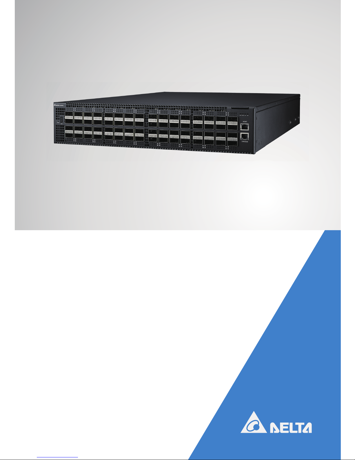
AG9064 Spine Switch
Installation Guide
agema.deltaww.com
Page 2

ii
AG9064 Spine Switch
Copyright
All specications and gures are subject to change without prior notice. Actual products may look
different from the photos.
All trademarks and logos mentioned in this guide are the properties of their respective holders.
Copyright © Delta Electronics, Inc. All rights reserved.
Regulatory and Safety Information
This product has been tested in accordance to, and complies with the following safety standards and
electromagnetic compatibility (EMC) inspection standards.
Emissions
Applicable standard
• AS/NZS CISPR 32: Class A
• ICES-003
• EN55032: Class A
• VCCI Class A
• FCC CFR 47 Part 15, Subpart B Class A
Safety
Applicable standard
• EN 60950-1, Second Edition
• UL 60950-1, Second Edition
• CAN/CSA C22.2 No. 60950-1-07, Second Edition
• IEC 60950-1, Second Edition Including All National
Immunity
Applicable standard
• EN 55024
• EN 61000-3-2: Harmonic Current Emissions
• EN 61000-3-3: Voltage Fluctuations and Flicker
• EN 61000-4-2: ESD
• EN 61000-4-3: Radiated Immunity
• EN 61000-4-4: EFT
• EN 61000-4-5: Surge
• EN 61000-4-6: Low Frequency Conducted Immunity
• EN61000-4-8: Power Frequency magnetic eld
• EN61000-4-11: Voltage dips and interruption
EU RoHS Compliant
Applicable standard All AG-Series components are EU RoHS compliant
Page 3
iii
Warning: Fiber Optic Port Safety
When using a ber optic port, never look at the transmit laser while it is powered
on. Also, never look directly at the ber TX port and ber cable ends when they are
powered on.
Avertissement : Consignes de sécurité concernant le port de fibre optique
Ne regardez jamais le faisceau de laser émis activé lorsque vous utilisez un port de
bre optique. Également, ne regardez jamais le port de bre TX et les extrémités du
câble du bre directement lorsqu’ils sont activés.
CAUTION
Lithium Battery Caution
Danger of explosion if battery is incorrectly replaced. Replace only with same or equivalent type.
Dispose batteries according to manufacturer’s instructions.
Disposal of a BATTERY into re or a hot oven, or mechanically crushing or cutting of a BATTERY, that
can result in an EXPLOSION.
Leaving a BATTERY in an extremely high temperature surrounding environment that can result in an
EXPLOSION or the leakage of ammable liquid or gas.
A BATTERY subjected to extremely low air pressure that may result in an EXPLOSION or the leakage
of ammable liquid or gas.
Grounding Caution
This equipment must be grounded and the power cord for product should be connected to a socketoutlet with earthing connection.
MISE EN GARDE
Mise en garde concernant la pile au lithium
Risque d’explosion si la pile est remplacée incorrectement. Remplacez-la avec une pile semblable ou
de même type uniquement. Éliminez les piles selon les directives du fabricant.
L’élimination de la PILE dans un feu, un four chaud ou un broyeur mécanique peut provoquer une
EXPLOSION.
L’exposition de la PILE à une température ambiante extrêmement élevée peut provoquer une
EXPLOSION ou la fuite d’un liquide ou d’un gaz inammable.
L’exposition de la PILE à une pression atmosphérique extrêmement basse peut provoquer une
EXPLOSION ou la fuite d’un liquide ou d’un gaz inammable.
Mise en garde concernant la mise en terre
Cet équipement doit être mis à terre et le cordon d’alimentation du produit doit être branché à une
prise mise à terre.
Page 4

iv
AG9064 Spine Switch
Table of Contents
Chapter 1: Introduction -------------------------------------------------------------------1
1.1 Overview ------------------------------------------------------------------------------------ 1
1.2 Package Content ------------------------------------------------------------------------- 1
1.3 Features------------------------------------------------------------------------------------- 2
Chapter 2: Appearance and Mechanism --------------------------------------------3
2.1 Product Overview ------------------------------------------------------------------------- 3
2.2 LED Identication ------------------------------------------------------------------------- 4
2.3 System Requirements ------------------------------------------------------------------- 7
2.4 Data Center Deployment --------------------------------------------------------------- 8
2.5 Power Supply Modules ------------------------------------------------------------------ 9
2.6 Fan Tray Module -------------------------------------------------------------------------10
Chapter 3: Installation ------------------------------------------------------------------- 11
3.1 Mounting -----------------------------------------------------------------------------------11
3.2 Installing an Optional QSFP/QSFP28 Transceiver ------------------------------14
3.3 Connecting to the Console Port ------------------------------------------------------15
3.4 Connecting to a Power Source -------------------------------------------------------15
Chapter 4: Making the Network Connections ----------------------------------- 18
4.1 Twisted-pair Connections --------------------------------------------------------------18
4.2 Fiber Optic Connections ---------------------------------------------------------------19
4.3 Ethernet Cabling -------------------------------------------------------------------------20
Appendix 1 : Technical Specifications --------------------------------------------- 21
Appendix 2 : Warranty ------------------------------------------------------------------- 22
Limited and Support Warranty -------------------------------------------------------------22
Technical Support -----------------------------------------------------------------------------22
Page 5

1
Chapter 1: Introduction
1.1 Overview
The AG9064 is a high performance, high density, 2RU, next generation Spine switch with
target application for Enterprise Campus Backbone, Data Center and Service Provider
deployment. It has sixty-four 100GbE QSFP28 ports which provides 6.4Tbps bandwidth
congurable to multi-rate 40/100GbE at desired fabric speed. In addition to rich bandwidth,
the AG9064 supports programmability capability, enables future-proof new features and
protocols and also has comprehensive capability on layer 2 and layer 3 features, including
STP, VLAN, QinQ, Trunk, QoS, LAG, full IPv4/IPv6 routing, RIP, OSPF, IGMP, DVMRP,
PIM-DM, PIM-SM, ACL, etc. The AG9064 also aims to next generation network also supports
advanced features such as VxLAN, L2GRE, NVGRE, GENEVE, NSH, MPLS, TRIL PPB-TE
L2/L2 in L3 Tunneling, Server Virtualization VN-Tag, VEPA, ow control PFC and ETS to meet
DCB network requirements. To provide a clear path to software-dened data center, AG9064
supports ONIE for zero touch installation of alternating network operating systems.
1.2 Package Content
After unpacking this switch, check the contents to be sure you have received all the
components. Then, before beginning the installation, be sure you have all other necessary
installation equipment.
• The AG9064 switch
• AC power supply for AC version or DC power supply for DC version
• Rack-mounting kits
• 2 x Velcro strips
• Installation guide
If any item is missing or damaged, contact the vendor immediately, see “Technical Support”.
Page 6

2
AG9064 Spine Switch
1.3 Features
The following lists the key main features of AG9064 switch:
• 64 x 100GbE QSFP28 ports, support splitter cable
• 1 x OOB BMC management port
• 1 x Console port (RJ-45 type)
• 1 x USB port
• Hot plugging redundant power supply support
• 4 Fan modules
• System / Fan / Power status LED indication
• On board high performance CPU system with large memory
• Internal power supply: 1300W (AC version) or 1300W (DC version)
• Standard 2RU chassis high
• 6.4 Tbps switching bandwidth
• Automatic address learning function to build the packet-forwarding information table. The
table contains up to 264K MAC addresses
• Low pin-to-pin latency: Cut-Through & Store and Forward Mode
• 42MB of packet buffer memory
• Support Jumbo Frame up to 9Kbyte
Page 7

3
Chapter 2: Appearance and Mechanism
2.1 Product Overview
2.1.1 Front View
Management port x 1
USB port x 1
QSFP28 ports x 64
RJ-45 Console port x 1
(Figure 2-1: Front View)
2.1.2 Rear View
Redundant PSU x 2
4 Fan tray slots
(Figure 2-2: Rear View)
NOTE:
The switch supports up to two PSUs. However, it might shipped with one power supply
pre-installed in the rear panel of the switch based on the SKU ordered. User can purchase
an additional PSU for redundancy.
Page 8
4
AG9064 Spine Switch
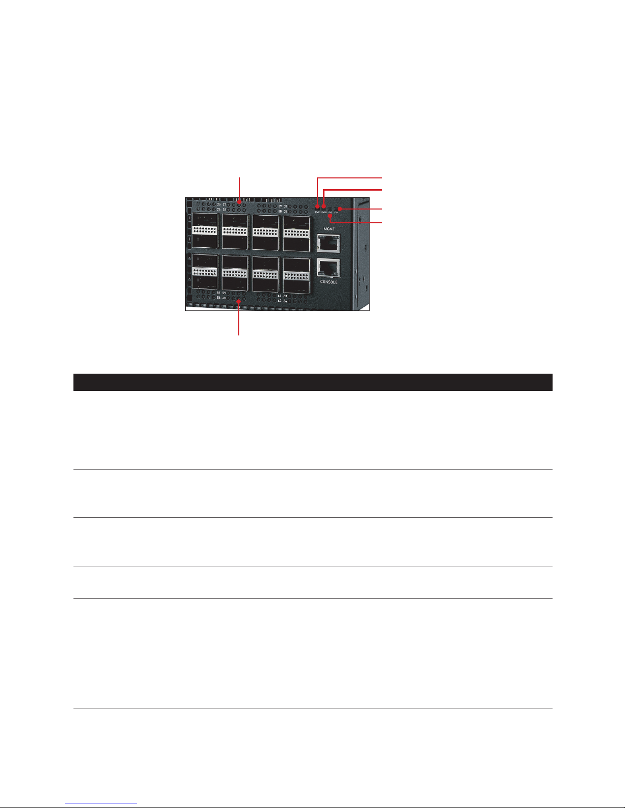
2.2 LED Identification
This section provides an overview of the front and rear LEDs.
2.2.1 Front LEDs
Upper QSFP28 Port LED
Lower QSFP28 Port LED
Power 1 LED
Power 2 LED
System LED
Fan LED
(Figure 2-3: Front LED Identification)
LED Description
System LED
• Off – Power is off
• Solid Green – Normal operation
• Blinking Green – Booting
• Solid Amber – BMC hang, I/O port module fault
• Solid Red – CPU hang, System over current, System over voltage
Power 1 LED
• Solid Green – Power Supply 1 is supplied to the switch & operating normally
• Solid Red – Power Supply 1 is failed
• Off – Power is disconnected
Power 2 LED
• Solid Green – Power Supply 2 is supplied to the switch & operating normally
• Solid Red – Power Supply 2 is failed
• Off – Power is disconnected
Fan LED
• Solid Green – FAN operating normally
• Solid Red – FAN is failed
100G QSFP28
slots
Four LEDs /
port
LED1 (Solid Lighting – Linkup; Blinking – Activity)
• Solid Green – 100G Operation
• Solid White – 50G Operation
• Solid Amber – 40G Operation
• Solid Blue – 25G Operation
• Solid Purple – 10G Operation
• Off – No Link
Page 9

• Appearance and MechanismChapter 2
5
LED Description
100G QSFP28
slots
Four LEDs /
port
(continue)
LED 2 (Solid Lighting – Linkup; Blinking – Activity)
• Solid Blue – 25G Operation
• Solid Purple – 10G Operation
• Off – No link
LED3 (Solid Lighting – Linkup; Blinking – Activity)
• Solid White – 50G Operation
• Solid Amber – 40G Operation
• Solid Blue – 25G Operation
• Solid Purple – 10G Operation
• Off – No Link
LED 4 (Solid Lighting – Linkup; Blinking – Activity)
• Solid Blue – 25G Operation
• Solid Purple – 10G Operation
• Off – No link
Management
ports
(Two LEDs per
port)
Link LED: (on the left side)
• Off – No link is established on the port
• Solid Yellow – A valid link at 10/100Mbps is established on the port
• Solid Green – A valid link at 1000Mbps is established on the port
Act LED: (on the right side)
• Off – No link is established on the port
• Blinking Green – Activity, transmitting or receiving packet at this port
Page 10

6
AG9064 Spine Switch
2.2.2 Rear LEDs
PSU LED
Fan LED
(Figure 2-4: Rear LED Identification)
LED Description
Fan LED
• Green – FAN operating normally
• Red – FAN failed
PSU LED
• Off – Power failure or no power
• Solid Green – Power is ok
Page 11

• Appearance and MechanismChapter 2
7
2.3 System Requirements
Component Requirement
System requirements
Switch fabric capacity Non-blocking full wire speed on all packet sizes
Forwarding architecture Store and forward or cut-through
Port packet forwarding rate
(at 64 Bytes)
• 148,000,000 pps (100GbE)
• 59,520,000 pps (40GbE)
• 14,880,000 pps (10GbE)
MAC address entries
supported
Up to 264K entries
Memory type
42MB buffer memory
OOB port 10/100/1000Mbps, auto sensing, auto negotiation
Spanning Tree Support
• Support IEEE802.1d STP
• Support IEEE802.1s MSTP
• Support IEEE802.1w RSTP
L3 Hosts IPv4 up to 128K; IPv6 up to 64K
L3 LPM
• w/o uRPF: IPv4 up to 384K; IPv6/64 up to 254K; IPv6/128 up to
128K
• w/ uRFP: IPv4 up to 24K; IPv6/64 up to 20K; IPv6/128 up to 4K
• T-CAM-only: IPv4 up to 32K; IPv6/64 up to 16K; IPv6/128 up to 8K
L3 Multicast Groups 8K
Serial Console
• Provide visual feedback of the boot process to the user
• Timeout after period of inactivity
Port Trunking IEEE802.3ad Link Aggregation (LAG) up to 2K
Port requirements
Speed Capability per Port
• 40/100GbE (QSFP28 port)
• Support for 10G/25G/50G Breakout Cables
Full-Duplex Flow Control Support the IEEE 802.3x PAUSE frame
Page 12

8
AG9064 Spine Switch
2.4 Data Center Deployment
The following gure illustrates the converged Ethernet data center deployment.
Spine
Leaf
100G uplink
100G downlink100G downlink
AG9032 v1
100G downlink
AG9032 v1
100G downlink
AG9032 v1
AG9064 AG9064 AG9064 AG9064
AG9032 v2
(Figure 2-5: Converged Ethernet Data Center Deployment)
Super Spine
Controller
100GbE Spine 100GbE Spine
AG9064
Spine
AG9064, AG9032 v1,
AG9032 v2, AG8032
Leaf
AG5648V1, AG7648,
AG7648C
Pod 1
Spine
Leaf
Pod N
(Figure 2-6: PoD based Hyper-Scale Data Center Application)
Page 13

• Appearance and MechanismChapter 2
9
2.5 Power Supply Modules
The power supply modules are hot-swappable power supply units (PSUs) for the switch.
You can install up to two PSUs. The PSUs operate in a load-sharing mode and provides 1+1
redundancy.
(Figure 2-7: Power Supply Unit)
NOTE:
1+1 redundancy is a system where a switch power supply is backed up by
another switch power supply in a load-sharing mode. If one power supply fails,
the other power supply takes over the full load of the switch.
WARNING:
• The switch includes plug-in power supply and fan tray modules that are
installed into its chassis. All modules have a front-to-back airow direction.
• Risk of explosion if battery is replaced by an incorrect type. Dispose of used
batteries according to the instructions.
• Remove the power cable from the module prior to removing the module
itself. Power cable must not be connected prior to insertion in the chassis or
equivalent.
AVERTISSEMENT:
• Le commutateur comporte des modules de bloc d’alimentation enchable
et de cassette de ventilation dans son châssis. La circulation d’air se fait de
l’avant vers l’arrière dans tous les modules.
• Risque d’explosion si la pile est remplacée par une de type différent. Suivez
les instructions pour éliminer les piles usées.
• Débranchez le câble d’alimentation du module avant de retirer ce dernier. Le
câble d’alimentation ne doit pas être branché avant l’insertion des modules
dans le châssis ou ailleurs.
Page 14

10
AG9064 Spine Switch
2.6 Fan Tray Module
The fan tray module is part of the switch air cooling system that provides cooling for the
switch. You must install the fan tray module in the switch that matches the airow direction of
the installed power supply unit.
(Figure 2-8: Fan Tray Module)
Page 15

11
Chapter 3: Installation
3.1 Mounting
This switch can be mounted in a standard 19-inch equipment rack or on a horizontal surface.
Mounting instructions for each type of site follow.
3.1.1 Rack Mounting
Prior rack mounting the switch, pay particular attention to the following factors:
• Mechanical Loading: Do not place any equipment on top of a rack-mounted unit.
• Circuit Overloading: Be sure that the supply circuit to the rack assembly is not overloaded.
• Grounding: Rack-mounted equipment should be properly grounded. Particular attention
should be given to supply connections other than direct connections to the mains.
To rack-mount devices:
1. Install the front mounting bracket to the device using the six M4 screws provided in the rack
mounting kit.
(Figure 3-1: Installing the Front Mounting Bracket)
2. Align the front mounting bracket to the rack holes. Then secure the front mounting bracket
using the screws.
NOTE:
Rack screws and clip nuts are not supplied in the rack-mounting kit.
CAUTION:
Due to the switch’s weight, it should be installed by at least two people.
MISE EN GARDE:
À cause du poids du commutateur, au moins deux personnes doivent l’installer.
Page 16

12
AG9064 Spine Switch
(Figure 3-2: Securing the Front Mounting Bracket)
3. From the rear side of the device, install the rear mounting brackets on both sides of the
device.
(Figure 3-3: Installing the Rear Mounting Brackets)
4. Align the rear mounting brackets to the rack holes. Then secure the rear mounting brackets
using the screws.
(Figure 3-4: Securing the Rear Mounting Brackets)
5. If installing a single switch only, go to “Connecting to a Power Source”.
6. If installing multiple switches, mount them in the rack, one below the other, in any order.
Page 17

• InstallationChapter 3
13
3.1.2 Horizontal Surface Mounting
The switch includes four pre-installed rubber feet for horizontal surface mounting.
To mount devices on a horizontal surface, follow these steps:
1. Attach the four adhesive feet to the bottom of the rst switch.
(Figure 3-5: Attaching the Adhesive Feet)
2. Set the device on a at horizontal surface near an AC power source, making sure there are
at least two inches of space on all sides for proper air ow.
3. If installing a single switch only, go to “Connecting to a Power Source”.
4. If installing multiple switches, attach four adhesive feet to each one, then place each device
squarely on top of the one below, in any order.
Page 18

14
AG9064 Spine Switch
3.2 Installing an Optional QSFP/QSFP28 Transceiver
The QSFP28 slots support the following optional QSFP/QSFP28 transceivers:
• 100GBASE-SR4
• 100GBASE-LR4
• 100GBASE AOC (Active Optical Cable)
• 100GBASE DAC (Direct Attached Cable)
• 100G to 4x25G AOC
• 100G to 4x25G DAC
• 40GBASE-SR
• 40GBASE-LR4
• 40GBASE AOC (Active Optical Cable)
• 40GBASE DAC (Direct Attached Cable)
(Figure 3-6: Inserting a QSFP/QSFP28 Transceiver into a Slot)
To install a QSFP/QSFP28 transceiver, follow these steps:
1. Consider network and cabling requirements to select an appropriate QSFP/QSFP28
transceiver type.
2. Insert the transceiver with the optical connector facing outward and the slot connector
facing down. Note that QSFP/QSFP28 transceivers are keyed so they can only be installed
in one orientation.
3. Slide the QSFP/QSFP28 transceiver into the slot until it clicks into place.
NOTE:
• QSFP/QSFP28 transceivers are hot-swappable. The switch does not need
to be powered off before installing or removing a transceiver. However,
always rst disconnect the network cable before removing a transceiver.
• QSFP/QSFP28 transceivers are not provided in the switch package.
• QSFP28 Ports to SFP28 Ports: The AG9064 also supports splitting a
100G QSFP28 port into 25G ports via the breakout cables. Do consult your
software provider for port mode change and conguration.
Page 19

• InstallationChapter 3
15
3.3 Connecting to the Console Port
This port is used to connect a console device to the switch through a nullmodem serial cable.
The console device can be a PC or workstation running a VT-100 terminal emulator, or a VT100 terminal.
NOTE:
An RJ-45-to-DB-9 cable is not supplied with the switch for connecting to a PC’s
RS-232 serial DB-9 DTE port.
DP-9 port
RJ-45 connector
(Figure 3-7: Console Port Connection)
3.4 Connecting to a Power Source
3.4.1 Installing an AC Power Supply
To connect a switch to a power source:
1. Insert the power cable plug directly into the AC socket of a PSU located at the back of the
switch.
Power socket
(Figure 3-8: Power Socket)
2. Plug the other end of the cable into a grounded, 3-pin, AC power source.
NOTE:
For International use, you may need to change the AC line cord. You must use a
line cord set that has been approved for the socket type in your country.
3. Check the PSU and front-panel LEDs as the device is powered on to be sure that AC
power is being received and the PWR1 LED is on. If not, check that the power cable is
correctly plugged in.
Page 20

16
AG9064 Spine Switch
4. Repeat steps 1 and 2 when a second PSU module is installed.
Two installed PSU modules operate in a load-sharing mode and provide 1+1 redundancy.
3.4.2 Installing a DC Power Supply
Two types of connection to a power source:
a. DC power cord for DC source connection
1. Insert the power cable plug directly into the DC socket of a PSU located at the back of the
switch.
GND
-48V(-DC)
-48V_RTN (+DC)
(Figure 3-9: Installing a DC Power Supply and Power Cable)
2. Plug the other end of the cable into DC power source. This product is intended to be
supplied by DC power source with rated -36V - -72Vdc, 42A minimum, Tma = 45 degree C,
and the altitude of operation = 5000 m. The power cable should be 14AWG (42A minimum,
-36V minimum).
CAUTION:
• Reversing polarity when connecting DC power wires can
permanently damage the power supply or the system.
• Always disconnect the power cable from power source before you
service the power supply slots.
MISE EN GARDE:
• L’inversion de la polarité des câbles d’alimentation CC lors de
leur branchement peut endommager irréversiblement le bloc
d’alimentation ou le système.
• Débranchez le câble d’alimentation de l’unité d’alimentation avant
l’entretien des fentes du bloc d’alimentation.
3. Check the PSU and front-panel LEDs as the device is powered on to be sure that DC
power is being received and the PWR1 LED is on. If not, check that the power cable is
correctly plugged in.
4. Repeat steps 1 and 2 when a second PSU module is installed.
Two installed PSU modules operate in a load-sharing mode and provide 1+1 redundancy.
Page 21

• InstallationChapter 3
17
b. Adapter connector for DC source connection
1. Attach the connector directly into the DC socket of a PSU located at the back of the switch.
GND
-48V(-DC)
-48V_RTN (+DC)
(Figure 3-10: Assembling a DC Connector and Power Wires)
2. Plug the other end of power wires into DC power source. This product is intended to be
supplied by DC power source with rated -36V - -72Vdc, 42A minimum, Tma = 45 degree C,
and the altitude of operation = 5000 m. The power cable should be 14AWG (42A minimum,
-36V minimum).
CAUTION:
• Reversing polarity when connecting DC power wires can
permanently damage the power supply or the system.
• Always disconnect the power cable from power source before you
service the power supply slots.
MISE EN GARDE:
• L’inversion de la polarité des câbles d’alimentation CC lors de
leur branchement peut endommager irréversiblement le bloc
d’alimentation ou le système.
• Débranchez le câble d’alimentation de l’unité d’alimentation avant
l’entretien des fentes du bloc d’alimentation.
3. Check the PSU and front-panel LEDs as the device is powered on to be sure that DC
power is being received and the PWR1 LED is on. If not, check that the power cable is
correctly plugged in.
4. Repeat steps 1 and 2 when a second PSU module is installed.
Two installed PSU modules operate in a load-sharing mode and provide 1+1 redundancy.
Page 22

18
AG9064 Spine Switch
Chapter 4: Making the Network Connections
The AG9064 switch is designed to provide high-speed, lossless Ethernet connections
between server racks through its 100G QSFP ports. This chapter describes how to make
network connections to the switch.
4.1 Twisted-pair Connections
The switch’s Management port connection requires an unshielded twisted-pair (UTP)
cable with RJ-45 connectors at both ends. Use Category 5, 5e or 6 cable for 1000BASE-T
connections, Category 5 or better for 100BASE-TX connections, and Category 3 or better for
10BASE-T connections.
4.1.1 Cabling Guidelines
The RJ-45 port on the switch supports an automatic MDI/MDI-X pinout conguration, so
you can use a standard straight-through twisted-pair cable to connect to any other network
device (PCs, servers, switches, routers, or hubs).
4.1.2 Connecting to the Management Port
1. Attach one end of a twisted-pair cable segment to the link device’s RJ-45 connector.
RJ-45 connector
(Figure 4-1: Making a Connection to the Management Port)
2. Attach the other end to the Management port on the switch.
Make sure the twisted pair cable does not exceed 100 meters (328 ft) in length.
3. When the connection is made, the Mgmt LED (on the switch) will light green to indicate that
the connection is valid.
Page 23

• Making the Network ConnectionsChapter 4
19
4.2 Fiber Optic Connections
Optional 100G QSFP28 transceivers can be used for ber connections from the switch to
other network devices in the data center. A QSFP28 transceiver may also be used for long
distance connections to devices at another site.
WARNING:
• When selecting a ber QSFP28 device, considering safety, please
make sure that it can function at a temperature that is not less than the
recommended maximum operational temperature of the product. You must
also use an approved QSFP28 transceiver.
AVERTISSEMENT:
• Pour des raisons de sécurité lors de la sélection d’un appareil avec la bre
QSFP28, veuillez vous assurer qu’il peut fonctionner à une température
qui n’est pas plus basse que la température de fonctionnement maximale
recommandée pour le produit. Vous devez également utiliser un émetteurrécepteur QSFP28 homologué.
The following gure illustrates the QSFP28 port ber connection.
(Figure 4-2: Making QSFP28 Port Fiber Connection)
Page 24

20
AG9064 Spine Switch
4.3 Ethernet Cabling
To ensure proper operation when installing the switch into a network, make sure that the
current cables are suitable for 10BASE-T, 100BASE-TX or 1000BASE-T operation. Check the
following criteria against the current installation of your network:
• Cable type: Unshielded twisted pair (UTP) or shielded twisted pair (STP) cables with
RJ-45 connectors; Category 3 or better for 10BASE-T, Category 5 or better for
100BASE-TX, and Category 5, 5e or 6 for 1000BASE-T.
• Protection from radio frequency interference emissions
• Electrical surge suppression
• Separation of electrical wires (switch related or other) and electromagnetic elds from
data based network wiring
• Safe connections with no damaged cables, connectors or shields
Page 25

21
Appendix 1 : Technical Specifications
Item Description
Key components
Switch controller
BCM56970 x 1
PHY
I210-AT x 1 (for Management port)
CPU
Intel Broadwell D1527 Quad Core
Flash Rom 32MB SPI Flash
System Memory 16GB DDR4-SO-DIMM * 2
mSATA Device 128GB SSD M.2 SSD
BMC AST2520, 8GB DDR3, 32MB Flash
TPM ST33HTP
Network Protocol and Standards Compatibility
Network protocol/
compatibility
• IEEE 802.3 10Base-T on console port
• IEEE 802.3u 100Base-TX on console port
• IEEE 802.3ab 1000BASE-T on console port
• IEEE 802.3x Flow-Control
• IEEE 802.3z 1000BASE-X
• IEEE 802.3ae 10Gb/s Ethernet
Interface Information
Interface
• Quad Small Form-factor Pluggable (QSFP28) slot x 64
• 10/100/1000Mbps Management port with BMC support x 1
• RJ45 Console port x 1
• USB port x 1
Power Supply Unit
Type AC-in PSU DC-in PSU
Max. output power
1300W 1300W
Input voltage
AC 110 - 220V DC -36 - -72V
Output voltage
DC 12V DC 12V
Physical
Dimensions (W x D x H)
438.5 x 500 x 87.2 mm
Weight
13.15kg
Environmental Specifications
Operating temperature
0 to 40°C
Storage temperature -20 to 70°C
Operating humidity 10 to 90% RH
Storage humidity 5 to 95% RH
Page 26

22
AG9064 Spine Switch
Appendix 2 : Warranty
Limited and Support Warranty
Three Years End-User Guarantee.
The new product you purchased from Delta or Delta authorized resellers (“Resellers”) will be
free from defects in materials, workmanship, and design affecting normal use, for a period of
three (3) years from the original purchase date. This warranty does not include accessories
or any free bundled sales items which may have been delivered along with the product. The
original purchasing invoice and the serial number on your product are both required when you
request for any warranty service.
During the warranty period, products for which proper claims are made will, at Delta’s option,
be repaired or replaced at Delta’s expense. Customers may contact Delta’s technical support
for warranty services, which may be provided either through Resellers or by Delta directly.
Delta owns all parts removed from the repaired products. Delta will use new or reconditioned
parts made by various manufacturers to perform repairs and/or to build replacement products.
All replaced or repaired products will be warranted for the remainder of the original warranty
period or thirty (30) days, whichever is longer.
Unless otherwise having a separate service level agreement (SLA) with Delta, you may
only have any in-warranty product returned to Delta for repair or replacement in a normal
turnaround time which differs according to geographic areas.
EXCLUSIONS
This Guarantee does not apply to defects resulting from: improper or inadequate installation,
use, or maintenance; actions or modications by unauthorized third parties or the end user;
accidental or willful damage; or normal wear and tear.
Technical Support
• For software related technical support and product return policy, please contact your software
providers.
• For hardware related technical support, please send your e-mail to
AgemaTechSupport@deltaww.com.
• Please note that hardware related issues are limited to the following situations:
• System Self-Diagnostic Test Failure (if applicable)
• Product is physically damaged on arrival
• Missing items in the package (see “Package Content”)
• The product does not power on
• Fan failure
Page 27

• WarrantyAppendix 2
23
Return Policy
Any product returned to Delta or Resellers without prior Return Material Authorization (RMA)
from Delta will be considered an unauthorized return, and you will not receive any repair or
replacement for the product and Delta will not ship the product back to you. The authorization
will be provided through the e-mail: AgemaTechSupport@deltaww.com.
For in-warranty defective product return, you shall be responsible for proper packaging and
Delta will not take responsibility for any shipping damage due to your improper product
packaging.
Disclaimer
EXCEPT FOR THE WARRANTIES EXPRESSLY SET FORTH IN THIS “LIMITED AND
SUPPORT WARRANTY”, DELTA MAKES NO OTHER WARRANTIES REGARDING THE
PRODUCT, ANY PARTS INCORPORATED THEREIN OR ANY SERVICES PROVIDED
THEREWITH AND HEREBY DISCLAIMS ANY AND ALL SUCH OTHER WARRANTIES,
EXPRESS, IMPLIED OR STATUTORY, INCLUDING, BUT NOT LIMITED TO, ANY
WARRANTIES OF MERCHANTABILITY OR FITNESS FOR PARTICULAR PURPOSE,
WHICH ARE ALL HEREBY EXCLUDED.
Page 28

 Loading...