

Page 1
Delta Networking – Agema Family
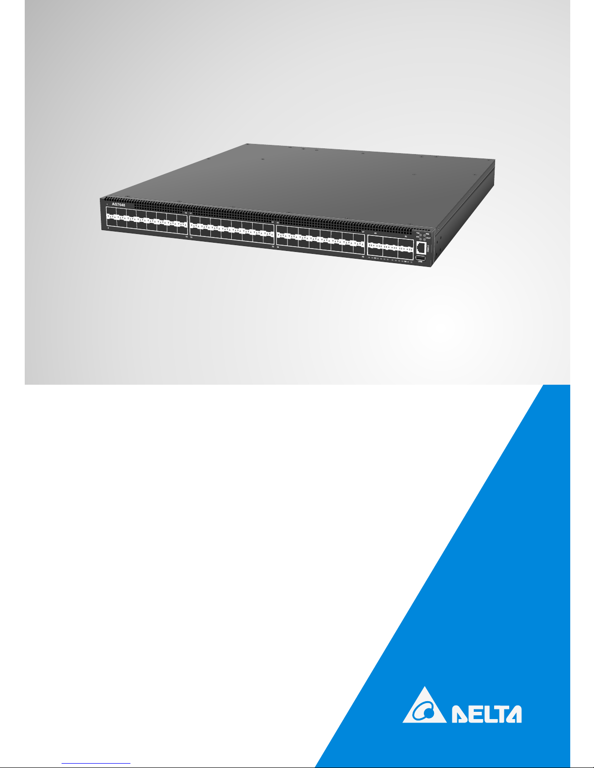
AG7648 ToR/leaf Switch
Installation Guide
Page 2

ii
AG7648 ToR/leaf Switch
Copyright
All specications and gures are subject to change without prior notice. Actual products may look
different from the photos.
All trademarks and logos mentioned in this guide are the properties of their respective holders.
Copyright © Delta Products Corporation. All rights reserved.
Regulatory and Safety Information
This product has been tested in accordance to, and complies with the following safety standards and
electromagnetic compatibility (EMC) inspection standards.
Emissions
Applicable standard
• AS/NZS CISPR 22: Class A
• ICES-003, Issue Class A
• EN 55022: Class A
• VCCI Class A
• FCC CFR 47 Part 15, Subpart B Class A
• CCC
Safety
Applicable standard
• EN 60950-1, Second Edition
• UL/CSA 60950-1, Second Edition
• IEC 60950-1, Second Edition Including All National
• CCC
Immunity
Applicable standard
• EN 300 386, EMC for Network Equipment
• EN 55024:
• EN 61000-3-2: Harmonic Current Emissions
• EN 61000-3-3: Voltage Fluctuations and Flicker
• EN 61000-4-2: ESD
• EN 61000-4-3: Radiated Immunity
• EN 61000-4-4: EFT
• EN 61000-4-5: Surge
• EN 61000-4-6: Low Frequency Conducted Immunity
• EN61000-4-8: Power Frequency magnetic eld
• EN61000-4-11: Voltage dips and interruptions
RoHS
Applicable standard All AG-Series components are EU RoHS compliant
Warning: Fiber Optic Port Safety
When using a ber optic port, never look at the transmit laser while it is powered
on. Also, never look directly at the ber TX port and ber cable ends when they are
powered on.
Page 3

iii
Table of Contents
Table of Contents
Chapter 1: Introduction -------------------------------------------------------------------1
1.1 Overview ------------------------------------------------------------------------------------ 1
1.2 Package Content -------------------------------------------------------------------------- 1
1.3 Features ------------------------------------------------------------------------------------- 2
Chapter 2: Appearance and Mechanism --------------------------------------------3
2.1 Product Overview ------------------------------------------------------------------------- 3
2.2 LED Identication ------------------------------------------------------------------------- 4
2.3 System Requirements ------------------------------------------------------------------- 6
2.4 Data Center Deployment ---------------------------------------------------------------- 6
2.5 Power Supply Modules ------------------------------------------------------------------ 7
2.6 Fan Tray Module -------------------------------------------------------------------------- 8
Chapter 3: Installation ---------------------------------------------------------------------9
3.1 Mounting ------------------------------------------------------------------------------------ 9
3.2 Installing an Optional SFP+/QSFP Transceiver ----------------------------------11
3.3 Connecting to the Console Port ------------------------------------------------------12
3.4 Connecting to a Power Source -------------------------------------------------------12
Chapter 4: Making the Network Connections ----------------------------------- 15
4.1 Twisted-pair Connections --------------------------------------------------------------15
4.2 Fiber Optic Connections ---------------------------------------------------------------16
4.3 Ethernet Cabling -------------------------------------------------------------------------17
Appendix 1 : Technical Specifications --------------------------------------------- 18
Appendix 2 : Warranty ------------------------------------------------------------------- 19
Limited and Support Warranty -------------------------------------------------------------19
Technical Support -----------------------------------------------------------------------------19
Page 4

1
AG7648 ToR/leaf Switch
Chapter 1: Introduction
1.1 Overview
The AG7648 is a high performance ToR/leaf bare metal switch design for today data
centers, who wish to avoid the vendor lock-in with integrated switch designs. The device has
forty-eight 10GbE SFP+ ports and six 40GbE QSFP ports which provides comprehensive
hardware capability on supporting layer 2, layer 3 and data center features, including VxLAN,
L2GRE, NVGRE and MPLS, etc.. The AG7648 switch also meets customers’ needs for both
capex and opex saving with their own choice of preferred network operation system (NOS).
1.2 Package Content
After unpacking this switch, check the contents to be sure you have received all the
components. Then, before beginning the installation, be sure you have all other necessary
installation equipment.
• AG7648 switch
• 1 x AC power supply for AC version or 1 x DC power supply for DC version
• Rack-mounting kits
• 2 x Velcro strips
• Installation guide
If any item is missing or damaged, contact the vendor immediately, see “Technical Suppor t”.
Page 5

2
• IntroductionChapter 1
1.3 Features
The following lists the main features of the AG7648 switch:
• 48 x 10GbE SFP+ ports
• 6 x 40GbE QSFP ports
• 1 x OOB Management
• 1 x Console port (RJ-45 type)
• 1 x USB port
• Hot plugging redundant power supply support
• 3 Fan modules
• System / Fan / Power status LED indication
• Extensive system LED and per port LEDs
• Internal power supply; Max output 460W (AC PSU) or 550W (DC PSU)
• Standard 1U chassis high and Rack mountable in standard 19” racks
• Alternate Store-Forward (ASF) mode - Cut-through is available to minimize the latency
• 720Gbps switching bandwidth (1440Gbps duplex)
• Automatic address learning function to build the packet-forwarding information table. The
table contains up to 288K MAC addresses
• 12 MB of packet buffer memory
• Support Jumbo Frame up to 12Kbyte
• VxLAN and NVGRE tunneling support in hardware for network virtualization
• Pre-loaded with Open Network Install Environment (ONIE) for automated loading of
compatible SwitchOS software
Page 6
3
AG7648 ToR/leaf Switch
Chapter 2: Appearance and Mechanism
2.1 Product Overview
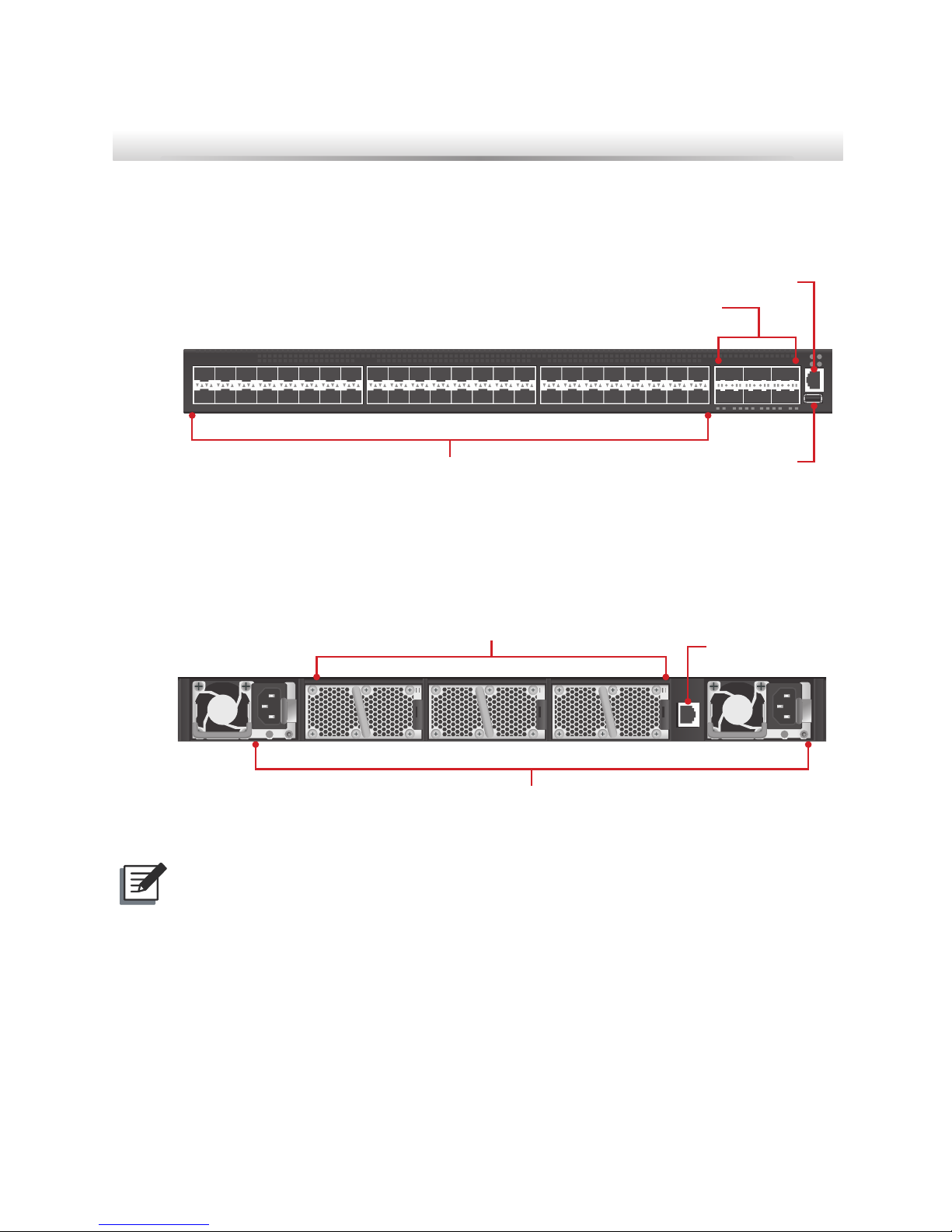
2.1.1 Front View
495047
48
333431
32
171815
16
1
AG7648
2
53
FAN
SYS
PWR
LOCAT
CONSOLE
54
USB
Ethernet port x 1
USB port x 1
QSFP port x 6
SFP+ port x 48
(Figure 2-1: Front View)
2.1.2 Rear View
< PWR1PWR2>
< FAN1
<<FAN2
<<<FAN3
MGMT
Redundant PSU x 2
3 Fan tray slots
Management port x 1
(Figure 2-2: Rear View)
NOTE:
The switch supports up to two PSUs. However, it is shipped with one power supply
pre-installed in the rear panel of the switch. You may purchase an additional PSU for
redundancy.
Page 7
4
• Appearance and MechanismChapter 2
2.2 LED Identification
This section provides an overview of the front and rear LEDs.
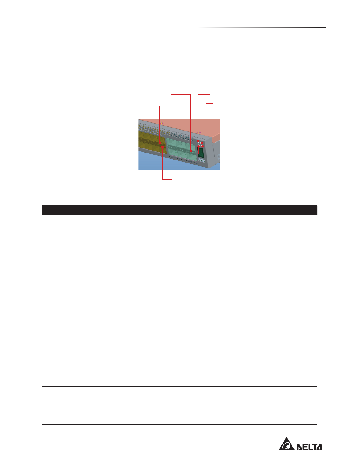
2.2.1 Front LEDs
Upper SFP+ Port LED
Lower SFP+ Port LED
QSFP+ Port LED Power LED
System LED
Locator LED
Fan LED
(Figure 2-3: Front LED Identification)
LED Description
System LED
• Off – Power is off
• Solid Green – Normal operation
• Blinking Green – Booting in progress
• Solid Yellow – Major Fault and the faults are Trafc Affecting
• Blinking Yellow – Minor Fault and Non-Trafc Affecting
Power LED
• Solid Green – Booting
• Off – Power is disconnected
When NOS is running:
• Solid Green – 2 Power Supplies are supplied to the switch and operating
normally
• Solid Yellow – Single power supply is installed and operating
• Blinking Yellow – 2 Power Supplies are installed, but only single power
supply is operating
Fan LED
• Solid Green – FAN operating normally
• Solid Yellow – FAN is failed including incompatible airow direction
Locator LED
• Off – LED is turned off
• Blinking Green – The locator function is enabled
• Solid Green – The locator function is disabled
10G SFP+ slots
(Two LEDs per
port)
• Off – No link
• Solid Green – A valid 10Gbps link
• Solid Yellow – A valid 1G link
• Blinking Green – Packet transmission or reception in progress
Page 8
5
AG7648 ToR/leaf Switch
LED Description
40G QSFP slots
(Two LEDs per
port)
• Off – No Link
• Solid Green – A valid 40Gbps Link
• Solid Amber – A valid 10Gbps Link
• Blinking Green – 40G speed, Packet transmission or reception in progress
• Blinking Amber – 10G speed, Packet transmission or reception in progress
Management
ports (Two LEDs
per port)
Link LED
• Off – No link is established on the port
• Solid Yellow – A valid link at 10/100Mbps is established on the port
• Solid Green – A valid link at 1000Mbps is established on the port
Act LED
• Off – No link is established on the port
• Blinking Green – Activity, transmitting or receiving packet at this port
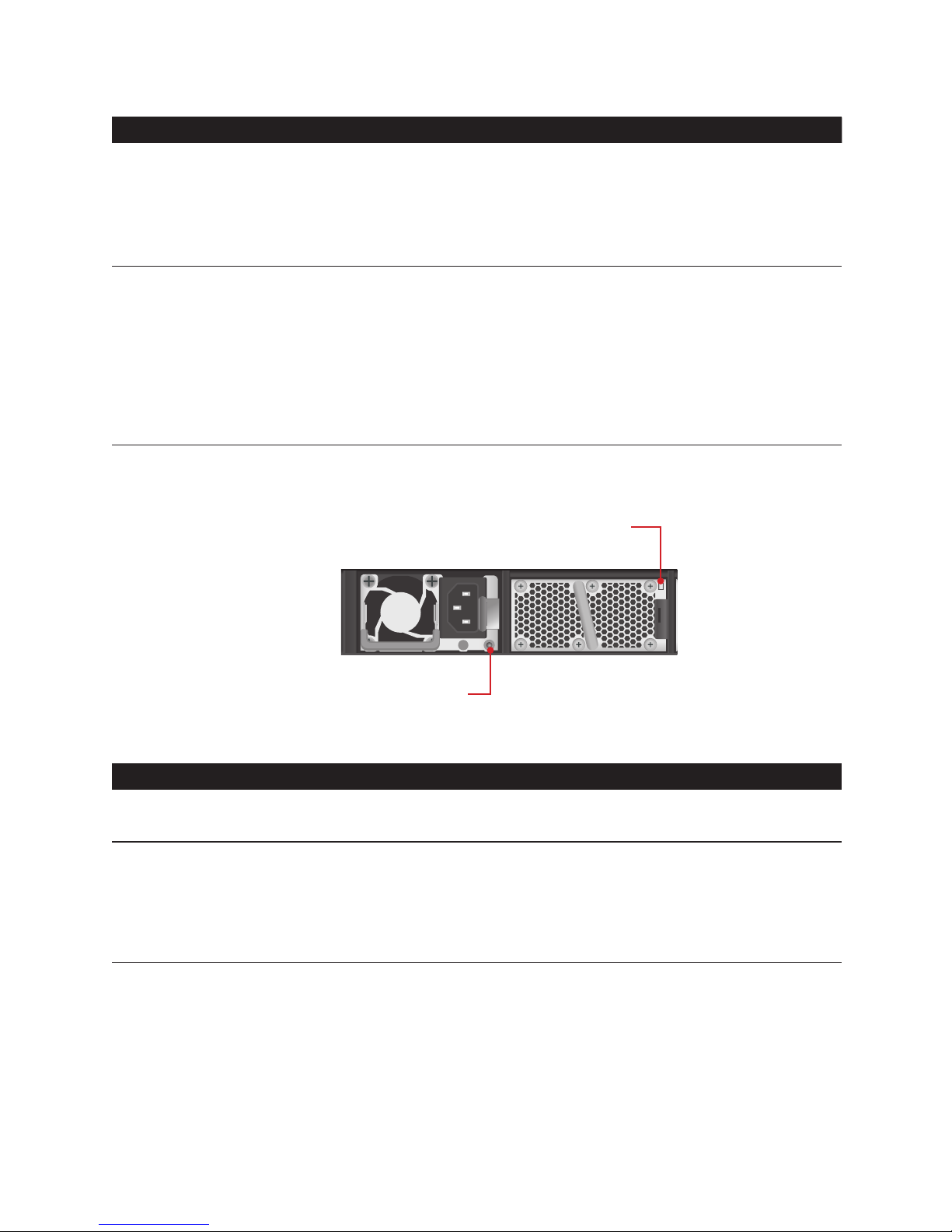
2.2.2 Rear LEDs
< PWR1
PWR2>
< FAN1
<<FAN2
<<<FAN3
MGMT
Power Supply LED
Fan tray LED
(Figure 2-4: Rear LED Identification)
LED Description
Fan tray LED
• Solid Green – Fan powered on at expected rotates per minute
• Solid Yellow – Fan failure
Power Supply
LED
• Off – No power
• Solid Green – Power is ok
• Solid Yellow – Power supply critical event causing a shutdown; failure
• Blinking Yellow – Power supply warning events where the power supply
continues to operate
Page 9

6
• Appearance and MechanismChapter 2
2.3 System Requirements
Component Requirement
System requirements
Switch fabric capacity Non-blocking full wire speed on all packet sizes
Forwarding architecture Store and forward or cut-through
Port packet forwarding rate
(at 64 Bytes)
1.44 Tbps
MAC address entries
supported
288K entries
Memory type
12 MBytes buffer memory
Console port Serial RS232 console ports (RJ45)
Serial console
• Provide visual feedback of the boot process to the user
• Timeout after period of inactivity
Port requirements
Speed Capability per Port 1G/10Gbps Auto-Sensing
Full-Duplex Flow Control Support the IEEE 802.3x PAUSE frame
2.4 Data Center Deployment
The following gure illustrates the converaged Ethernet data center deployment.
PWR1
PWR2
SYSFAN
29 3130 3225 2726 2821 2322 2417 1918 2013 1514 16 9 1110 125 76 81 32 4
MGMT
CONSOLE
USB
PWR1
PWR2
SYSFAN
29 3130 3225 2726 2821 2322 2417 1918 2013 1514 16 9 1110 125 76 81 32 4
MGMT
CONSOLE
USB
PWR1
PWR2
SYSFAN
29 3130 3225 2726 2821 2322 2417 1918 2013 1514 16 9 1110 125 76 81 32 4
MGMT
CONSOLE
USB
PWR1
PWR2
SYSFAN
29 3130 3225 2726 2821 2322 2417 1918 2013 1514 16 9 1110 125 76 81 32 4
MGMT
CONSOLE
USB
PWR1
PWR2
SYSFAN
29 3130 3225 2726 2821 2322 2417 1918 2013 1514 16 9 1110 125 76 81 32 4
MGMT
CONSOLE
USB
495047
48
333431
32
171815
16
1
AG7648
2
53
FAN
SYS
PWR
LOCAT
CONSOLE
54
USB
495047
48
333431
32
171815
16
1
AG7648
2
53
FAN
SYS
PWR
LOCAT
CONSOLE
54
USB
Spine
Leaf
AG8032 AG8032 AG8032 AG8032
AG7648
40GbE QSFP+ uplink
10GbE SFP+
AG7648 AG8032
10GbE SFP+ 40GbE QSFP+ or
10GbE SFP+ (breakout cable)
(Figure 2-5: Converaged Ethernet Data Center Deployment)
Page 10

7
AG7648 ToR/leaf Switch
495047
48
333431
32
171815
16
1
AG7648
2
53
FAN
SYS
PWR
LOCAT
CONSOLE
54
USB
495047
48
333431
32
171815
16
1
AG7648
2
53
FAN
SYS
PWR
LOCAT
CONSOLE
54
USB
srevreS edalBsrevreS edalB
Aggregation SwitchAggregation Switch
PWR1
PWR2
SYSFAN
29 3130 3225 2726 2821 2322 2417 1918 2013 1514 16 9 1110 125 76 81 32 4
MGMT
CONSOLE
USB
PWR1
PWR2
SYSFAN
29 3130 3225 2726 2821 2322 2417 1918 2013 1514 16 9 1110 125 76 81 32 4
MGMT
CONSOLE
USB
Core Switch
Console
Reset
Clear
Mode
Select
Act
Fdx
100
SwitchEngineFail
SelfTest
A
X1
Link
Mode
X2
X
3
X4 X
5
X7
X6
X8
A
X
1
Link
Mode
X
2
X3 X4
X
5
X7
X6
X8
A
X1
Link
Mode
X
2
X
3
X
4 X
5
X7X
6
X
8
A
X
1
Link
Mode
X2
X
3
X
4
X
5
X7X
6
X
8
Status
A
I
E
C
1
G
B
J
F
D
2
H
Modules
Power
Fan
A
X
1
Link
Mode
X
2 X3
X
4 X5
X7X
6
X
8
A
X1
Link
Mode
X2
X3
X
4
X
5
X
7
X
6
X8
A
X1
Link
Mode
X
2 X3 X
4
X5
X
7
X
6
X
8
A
X1
Link
Mode
X2 X
3 X
4
X
5
X
7
X
6
X8
A
X
1
Link
Mode
X
2
X3
X
4
X
5
X
7
X
6
X8
A
X1
Link
Mode
X2
X
3
X4 X
5
X7X
6
X
8
AG8032 AG8032
AG7648 AG7648
ToR (Access) SwitchToR (Access) Switch
(Figure 2-6: CLOS Network Architecture)
2.5 Power Supply Modules
The power supply modules are hot-swappable power supply units (PSUs) for the switch.
You can install up to two PSUs. The PSUs operate in a load-sharing mode and provides 1+1
redundancy.
(Figure 2-7: Power Supply Unit)
NOTE:
1+1 redundancy is a system where a switch power supply is backed up by
another switch power supply in a load-sharing mode. If one power supply fails,
the other power supply takes over the full load of the switch.
WARNING:
• The switch includes plug-in power supply and fan tray modules that are
installed into its chassis. All modules must have a front-to-back airow
direction, or back-to-front airow direction.
• Risk of explosion if battery is replaced by an incorrect type. Dispose of used
batteries according to the instructions.
• Remove the power cable from the module prior to removing the module
itself. Power cable must not be connected prior to insertion in the chassis or
equivalent.
Page 11

8
• Appearance and MechanismChapter 2
2.6 Fan Tray Module
The fan tray module is part of the switch air cooling system that provides cooling for the
switch. You must install the fan tray module in the switch that matches the airow direction
of the installed power supply unit.
(Figure 2-8: Fan Tray Module)
Page 12

9
AG7648 ToR/leaf Switch
Chapter 3: Installation
3.1 Mounting
This switch can be mounted in a standard 19-inch equipment rack or on a horizontal surface.
Mounting instructions for each type of site follow.
3.1.1 Rack Mounting
Prior rack mounting the switch, pay particular attention to the following factors:
• Mechanical Loading: Do not place any equipment on top of a rack-mounted unit.
• Circuit Overloading: Be sure that the supply circuit to the rack assembly is not overloaded.
• Grounding: Rack-mounted equipment should be properly grounded. Particular attention
should be given to supply connections other than direct connections to the mains.
To rack-mount devices:
1. Attach the two brackets to the device using the eight M4 screws provided in the rack
mounting kit.
NOTE:
The switch can also be mounted in a rack using a rack shelf or rack “L” brackets.
(Figure 3-1: Attaching the Brackets)
2. Mount the device in the rack, using four 12-24 rack-mounting screws.
NOTE:
Rack screws and clip nuts are not supplied in the rack-mounting kit.
CAUTION:
Due to the switch’s weight, it should be installed by at least two people.
Page 13

10
• InstallationChapter 3
(Figure 3-2: Installing the Switch in a Rack)
3. If installing a single switch only, go to “Connecting to a Power Source”.
4. If installing multiple switches, mount them in the rack, one below the other, in any order.
3.1.2 Horizontal Surface Mounting
The switch includes four pre-installed rubber feet for horizontal surface mounting.
To mount devices on a horizontal surface, follow these steps:
1. Attach the four adhesive feet to the bottom of the rst switch.
(Figure 3-3: Attaching the Adhesive Feet)
2. Set the device on a at horizontal surface near an AC power source, making sure there are
at least two inches of space on all sides for proper air ow.
3. If installing a single switch only, go to “Connecting to a Power Source”.
4. If installing multiple switches, attach four adhesive feet to each one, then place each device
squarely on top of the one below, in any order.
Page 14

11
AG7648 ToR/leaf Switch
3.2 Installing an Optional SFP+/QSFP Transceiver
The SFP+ slots support the following optional SFP+ transceivers:
• 10GBASE-CR
• 10GBASE-SR
• 10GBASE-SRL
• 10GBASE-LR
• 1000BASE-SX
• 1000BASE-LX
The QSFP+ slots support the following optional QSFP+ transceivers:
• 40GBASE-SR
• 40GBASE-LR4
• 40GBASE AOC (Active Optical Cable)
• 40GBASE DAC (Direct Attached Cable)
• 40G to 4x10G AOC
• 40G to 4x10G DAC
(Figure 3-4: Inserting an SFP+ Transceiver into a Slot)
(Figure 3-5: Inserting a QSFP Transceiver into a Slot)
To install a SFP+/QSFP transceiver, follow these steps:
1. Consider network and cabling requirements to select an appropriate SFP+/ QSFP
transceiver type.
2. Insert the transceiver with the optical connector facing outward and the slot connector
facing down. Note that SFP+/ QSFP transceivers are keyed so they can only be installed in
one orientation.
3. Slide the SFP+/ QSFP transceiver into the slot until it clicks into place.
NOTE:
• SFP+/QSFP transceivers are hot-swappable. The switch does not need to
be powered off before installing or removing a transceiver. However, always
rst disconnect the network cable before removing a transceiver.
• SFP+/QSFP transceivers are not provided in the switch package.
Page 15

12
• InstallationChapter 3
3.3 Connecting to the Console Port
This port is used to connect a console device to the switch through a nullmodem serial cable.
The console device can be a PC or workstation running a VT-100 terminal emulator, or a
VT-100 terminal. An RJ-45-to-DB-9 cable is supplied with the switch for connecting to a PC’s
RS-232 serial DB-9 DTE port. The pin assignments used in the RJ-45-to-DB-9 cable are
described below.
DP-9 port
RJ-45 connector
(Figure 3-6: Console Port Connection)
3.4 Connecting to a Power Source
3.4.1 Installing an AC Power Supply
To connect a switch to a power source:
1. Insert the power cable plug directly into the AC socket of a PSU located at the back of the
switch.
Power socket
(Figure 3-7: Power Socket)
2. Plug the other end of the cable into a grounded, 3-pin, AC power source.
NOTE:
For International use, you may need to change the AC line cord. You must use a
line cord set that has been approved for the socket type in your country.
3. Check the PSU and front-panel LEDs as the device is powered on to be sure that AC
power is being received and the Power LED is on. If not, check that the power cable is
correctly plugged in.
Page 16

13
AG7648 ToR/leaf Switch
4. Repeat steps 1 and 2 when a second PSU module is installed.
Two installed PSU modules operate in a load-sharing mode and provide 1+1 redundancy.
3.4.2 Installing a DC Power Supply
Two types of connection to a power source:
a. DC power cord for DC source connection
1. Insert the power cable plug directly into the DC socket of a PSU located at the back of the
switch.
GND
-48V(-DC)
-48V_RTN (+DC)
(Figure 3-8: Installing a DC Power Supply and Power Cable)
2. Plug the other end of the cable into DC power source. This product is intended to be
supplied by DC power source with rated -40 ~ -72Vdc, 16A minimum, Tma = 40 degree C,
and the altitude of operation = 3048 m. The power cable should be 14AWG (16A minimum,
72V minimum).
CAUTION:
• Reversing polarity when connecting DC power wires can
permanently damage the power supply or the system.
• Always disconnect the power cable from power source before you
service the power supply slots.
3. Check the PSU and front-panel LEDs as the device is powered on to be sure that DC
power is being received and the Power LED is on. If not, check that the power cable is
correctly plugged in.
4. Repeat steps 1 and 2 when a second PSU module is installed.
Two installed PSU modules operate in a load-sharing mode and provide 1+1 redundancy.
Page 17

14
• InstallationChapter 3
b. Adapter connector for DC source connection
1. Attach the connector directly into the DC socket of a PSU located at the back of the switch.
GND
-48V(-DC)
-48V_RTN (+DC)
(Figure 3-9: Assembling a DC Connector and Power Wires)
2. Plug the other end of power wires into DC power source. This product is intended to be
supplied by DC power source with rated -40 ~ -72Vdc, 16A minimum, Tma = 40 degree C,
and the altitude of operation = 3048 m. The power cable should be 14AWG (16A minimum,
72V minimum).
CAUTION:
• Reversing polarity when connecting DC power wires can
permanently damage the power supply or the system.
• Always disconnect the power cable from power source before you
service the power supply slots.
3. Check the PSU and front-panel LEDs as the device is powered on to be sure that DC
power is being received and the Power LED is on. If not, check that the power cable is
correctly plugged in.
4. Repeat steps 1 and 2 when a second PSU module is installed.
Two installed PSU modules operate in a load-sharing mode and provide 1+1 redundancy.
Page 18

15
AG7648 ToR/leaf Switch
Chapter 4: Making the Network Connections
The AG7648 switch is designed to provide high-speed, lossless Ethernet connections
between server racks through its 10G SFP+ or 40G QSFP ports. This chapter describes how
to make network connections to the switch.
4.1 Twisted-pair Connections
The switch’s Management port connection requires an unshielded twisted-pair (UTP)
cable with RJ-45 connectors at both ends. Use Category 5, 5e or 6 cable for 1000BASE-T
connections, Category 5 or better for 100BASE-TX connections, and Category 3 or better for
10BASE-T connections.
4.1.1 Cabling Guidelines
The RJ-45 port on the switch supports an automatic MDI/MDI-X pinout conguration, so
you can use a standard straight-through twisted-pair cable to connect to any other network
device (PCs, servers, switches, routers, or hubs).
4.1.2 Connecting to the Management Port
1. Attach one end of a twisted-pair cable segment to the link device’s RJ-45 connector.
RJ-45 connector
(Figure 4-1: Making a Connection to the Management Port)
2. Attach the other end to the Management port on the switch.
Make sure the twisted pair cable does not exceed 100 meters (328 ft) in length.
3. When the connection is made, the Mgmt LED (on the switch) will light green to indicate that
the connection is valid.
Page 19

16
• Making the Network ConnectionsChapter 4
4.2 Fiber Optic Connections
Optional 10G SFP+ or 40G QSFP transceivers can be used for ber connections from the
switch to other network devices in the data center. An SFP+ or QSFP transceiver may also
be used for long distance connections to devices at another site.
WARNING:
• This switch uses lasers to transmit signals over ber optic cable. The lasers
are compliant with the requirements of a Class 1 Laser Product and are
inherently eye safe in normal operation. However, you should never look
directly at a transmit port when it is powered on.
• When selecting a ber SFP+/QSFP device, considering safety, please
make sure that it can function at a temperature that is not less than the
recommended maximum operational temperature of the product. You must
also use an approved Laser Class 1 SFP+/QSFP transceiver.
The following gure illustrates the SFP+/QSFP port ber connection.
(Figure 4-2: Making SFP+ Port Fiber Connection)
(Figure 4-3: Making QSFP Port Fiber Connection)
Page 20

17
AG7648 ToR/leaf Switch
4.3 Ethernet Cabling
To ensure proper operation when installing the switch into a network, make sure that the
current cables are suitable for 10BASE-T, 100BASE-TX or 1000BASE-T operation. Check the
following criteria against the current installation of your network:
• Cable type: Unshielded twisted pair (UTP) or shielded twisted pair (STP) cables with RJ-
45 connectors; Category 3 or better for 10BASE-T, Category 5 or better for 100BASE-TX,
and Category 5, 5e or 6 for 1000BASE-T.
• Protection from radio frequency interference emissions
• Electrical surge suppression
• Separation of electrical wires (switch related or other) and electromagnetic elds from
data based network wiring
• Safe connections with no damaged cables, connectors or shields
Page 21

18
Appendix 1 : Technical Specifications
Item Description
Key components
Switch controller
BCM56854 x 1
PHY
BCM54616S x 1 (for console Management port)
CPU
Intel Rangeley C2338 Processor
Flash 16MB SPI
Storage 8GB mSATA SSD
System memory
2GB DDR3-SDRAM
Network Protocol and Standards Compatibility
Network protocol/
compatibility
• IEEE 802.3 10Base-T on console port
• IEEE 802.3u 100Base-TX on console port
• IEEE 802.3ab 1000BASE-T on console port
• IEEE 802.3x Flow-Control
• IEEE 802.3z 1000BASE-X
• IEEE 802.3ae 10Gb/s Ethernet
• IEEE 802.3ba: 40Gb/s Ethernet
Interface Information
Interface
• Small Form-factor Pluggable Plus (SFP+) slot x 48
• Quad Small Form-factor Pluggable (QSFP) slot x 6
• 10/100/1000Mbps console Management port x 1
• External Console port (RJ45) x 1
• USB port x 1
Power Supply Unit
Type AC-in PSU DC-in PSU
Max. output power
460W 550W
Input voltage
AC 100 ~ 240V DC -48 ~ -60V
Output voltage
DC 12V DC 12V
Physical
Dimensions (W x D x H)
438.5 x 460 x 43.5 mm (17.26 x 18.11 x 1.71 inches)
Weight
11.21 kg (24.71 lbs)
Environmental Specifications
Operating temperature
0 to 40°C
Storage temperature -20 to 70°C
Operating humidity 10 to 90% RH
Storage humidity 5 to 95% RH
Page 22

19
AG7648 ToR/leaf Switch
Appendix 2 : Warranty
Limited and Support Warranty
Three Years End-User Guarantee.
The new product you purchased from Delta or Delta authorized resellers (“Resellers”) will be
free from defects in materials, workmanship, and design affecting normal use, for a period of
three (3) years from the original purchase date. This warranty does not include accessories
or any free bundled sales items which may have been delivered along with the product. The
original purchasing invoice and the serial number on your product are both required when you
request for any warranty service.
During the warranty period, products for which proper claims are made will, at Delta’s option,
be repaired or replaced at Delta’s expense. Customers may contact Delta’s technical support
for warranty services, which may be provided either through Resellers or by Delta directly.
Delta owns all parts removed from the repaired products. Delta will use new or reconditioned
parts made by various manufacturers to perform repairs and/or to build replacement products.
All replaced or repaired products will be warranted for the remainder of the original warranty
period or thirty (30) days, whichever is longer.
Unless otherwise having a separate service level agreement (SLA) with Delta, you may
only have any in-warranty product returned to Delta for repair or replacement in a normal
turnaround time which differs according to geographic areas.
EXCLUSIONS
This Guarantee does not apply to defects resulting from: improper or inadequate installation,
use, or maintenance; actions or modications by unauthorized third parties or the end user;
accidental or willful damage; or normal wear and tear.
Technical Support
• For software related technical support and product return policy, please contact your software
providers.
• For hardware related technical support, please send your e-mail to
AgemaTechSupport@deltaww.com.
• Please note that hardware related issues are limited to the following situations:
• System Self-Diagnostic Test Failure
• Product is physically damaged on arrival
• Missing items in the package (see “Package Content”)
• The product does not power on
• Fan failure
Page 23

20
• WarrantyAppendix 2
Return Policy
Any product returned to Delta or Resellers without prior Return Material Authorization (RMA)
from Delta will be considered an unauthorized return, and you will not receive any repair or
replacement for the product and Delta will not ship the product back to you. The authorization
will be provided through the e-mail: AgemaTechSupport@deltaww.com.
For in-warranty defective product return, you shall be responsible for proper packaging and
Delta will not take responsibility for any shipping damage due to your improper product
packaging.
Disclaimer
EXCEPT FOR THE WARRANTIES EXPRESSLY SET FORTH IN THIS “LIMITED AND
SUPPORT WARRANTY”, DELTA MAKES NO OTHER WARRANTIES REGARDING THE
PRODUCT, ANY PARTS INCORPORATED THEREIN OR ANY SERVICES PROVIDED
THEREWITH AND HEREBY DISCLAIMS ANY AND ALL SUCH OTHER WARRANTIES,
EXPRESS, IMPLIED OR STATUTORY, INCLUDING, BUT NOT LIMITED TO, ANY
WARRANTIES OF MERCHANTABILITY OR FITNESS FOR PARTICULAR PURPOSE,
WHICH ARE ALL HEREBY EXCLUDED.
Page 24

 Loading...