

Page 1

INSTRUCTION MANUAL
20" Drill Press
(Model 70-200)
PART NO. 900615 (0012)
Copyright © 2000 Delta Machinery
ESPAÑOL: PÁGINA 17
To learn more about DELTA MACHINERY
visit our website at: www.deltamachinery.com.
For Parts, Service, Warranty or other Assistance,
please call
1-800-223-7278 (In Canada call 1-800-463-3582).
Page 2

2
SAFETY RULES
Woodworking can be dangerous if safe and proper operating procedures are not followed. As with all machinery, there are certain
hazards involved with the operation of the product. Using the machine with respect and caution will considerably lessen the possibility of personal injury. However, if normal safety precautions are overlooked or ignored, personal injury to the operator may result.
Safety equipment such as guards, push sticks, hold-downs, featherboards, goggles, dust masks and hearing protection can reduce
your potential for injury. But even the best guard won’t make up for poor judgment, carelessness or inattention. Always use com
mon sense and exercise caution in the workshop. If a procedure feels dangerous, don’t try it. Figure out an alternative procedure
that feels safer. REMEMBER: Your personal safety is your responsibility.
This machine was designed for certain applications only. Delta Machinery strongly recommends that this machine not be modified
and/or used for any application other than that for which it was designed. If you have any questions relative to a particular application, DO NOT use the machine until you have first contacted Delta to determine if it can or should be performed on the product.
Technical Service Manager
Delta Machinery
4825 Highway 45 North
Jackson, TN 38305
(IN CANADA: 505 SOUTHGATE DRIVE, GUELPH, ONTARIO N1H 6M7)
WARNING: FAILURE TO FOLLOW THESE RULES
MAY RESULT IN SERIOUS PERSONAL INJURY
1. FOR YOUR OWN SAFETY, READ INSTRUCTION MANUAL
BEFORE OPERATING THE TOOL. Learn the tool’s application
and limitations as well as the specific hazards peculiar to it.
2. KEEP GUARDS IN PLACE and in working order.
3. ALWAYS WEAR EYE PROTECTION.
4. REMOVE ADJUSTING KEYS AND WRENCHES. Form habit
of checking to see that keys and adjusting wrenches are removed
from tool before turning it “on”.
5. KEEP WORK AREA CLEAN. Cluttered areas and benches
invite accidents.
6. DON’T USE IN DANGEROUS ENVIRONMENT. Don’t use
power tools in damp or wet locations, or expose them to rain.
Keep work area well-lighted.
7. KEEP CHILDREN AND VISITORS AWAY. All children and
visitors should be kept a safe distance from work area.
8. MAKE WORKSHOP CHILDPROOF – with padlocks, master
switches, or by removing starter keys.
9. DON’T FORCE TOOL. It will do the job better and be safer at
the rate for which it was designed.
10. USE RIGHT TOOL. Don’t force tool or attachment to do a job
for which it was not designed.
11. WEAR PROPER APPAREL. No loose clothing, gloves, neck-
ties, rings, bracelets, or other jewelry to get caught in moving
parts. Nonslip footwear is recommended. Wear protective hair
covering to contain long hair.
12.
ALWAYS USE SAFETY GLASSES.
Wear safety glasses.
Everyday eyeglasses only have impact resistant lenses; they
are not safety glasses. Also use face or dust mask if cutting
operation is dusty. These safety glasses must conform to ANSI
Z87.1 requirements. Note: Approved glasses have Z87 printed
or stamped on them.
13. SECURE WORK. Use clamps or a vise to hold work when
practical. It’s safer than using your hand and frees both hands to
operate tool.
14. DON’T OVERREACH. Keep proper footing and balance at all
times.
15. MAINTAIN TOOLS IN TOP CONDITION. Keep tools sharp
and clean for best and safest performance. Follow instructions for
lubricating and changing accessories.
16. DISCONNECT TOOLS before servicing and when changing
accessories such as blades, bits, cutters, etc.
17. USE RECOMMENDED ACCESSORIES. The use of acces-
sories and attachments not recommended by Delta may cause
hazards or risk of injury to persons.
18. REDUCE THE RISK OF UNINTENTIONAL STARTING.
Make sure switch is in “OFF” position before plugging in power
cord.
19. NEVER STAND ON TOOL. Serious injury could occur if the
tool is tipped or if the cutting tool is accidentally contacted.
20. CHECK DAMAGED PARTS. Before further use of the tool, a
guard or other part that is damaged should be carefully checked
to ensure that it will operate properly and perform its intended
function – check for alignment of moving parts, binding of moving
parts, breakage of parts, mounting, and any other conditions that
may affect its operation. A guard or other part that is damaged
should be properly repaired or replaced.
21. DIRECTION OF FEED. Feed work into a blade or cutter
against the direction of rotation of the blade or cutter only.
22. NEVER LEAVE TOOL RUNNING UNATTENDED. TURN
POWER OFF. Don’t leave tool until it comes to a complete stop.
23. DRUGS, ALCOHOL, MEDICATION. Do not operate tool
while under the influence of drugs, alcohol or any medication.
24. MAKE SURE TOOL IS DISCONNECTED FROM POWER
SUPPLY while motor is being mounted, connected or reconnected.
25. THE DUST GENERATED by certain woods and wood prod-
ucts can be injurious to your health. Always operate machinery in
well ventilated areas and provide for proper dust removal. Use
wood dust collection systems whenever possible.
26.
WARNING: SOME DUST CREATED BY POWER
SANDING, SAWING, GRINDING, DRILLING, AND OTHER
CONSTRUCTION ACTIVITIES contains chemicals known to
cause cancer, birth defects or other reproductive harm. Some
examples of these chemicals are:
• lead from lead-based paints,
• crystalline silica from bricks and cement and other masonry
products, and
• arsenic and chromium from chemically-treated lumber.
Your risk from these exposures varies, depending on how often
you do this type of work. To reduce your exposure to these
chemicals: work in a well ventilated area, and work with
approved safety equipment, such as those dust masks that are
specially designed to filter out microscopic particles.
SAVE THESE INSTRUCTIONS
Page 3

3
ADDITIONAL SAFETY RULES
FOR DRILL PRESSES
1. DO NOT operate your drill press until it is complete-
ly assembled and installed according to the instructions.
2. IF YOU ARE NOT thoroughly familiar with the oper-
ation of drill presses, obtain advice from your supervisor,
instructor or other qualified person.
3. YOUR DRILL PRESS MUST be securely fastened to
a stand, workbench or floor. If there is any tendency for
the stand or workbench to move during operation, the
stand or workbench MUST be fastened to the floor.
4. NEVER turn the drill press “on” before clearing the
table of all objects (tools, scrap pieces, etc.).
5. NEVER start the drill press with the drill bit or cut-
ting tool in contact with the workpiece.
6. USE ONLY drill bits, cutters, sanding drums, and
other accessories with 5/8 shank or less.
7. ALWAYS keep hands and fingers away from the drill
bit or cutting tool.
8. DO NOT ATTEMPT to drill material that does not
have a flat surface, unless a suitable support is used.
9. AVOID awkward hand positions where a sudden slip
could cause a hand to move into the drill bit or cutting
tool.
10. TO PREVENT ROTATION OF THE WORKPIECE,
ALWAYS clamp work securely to the table if it is too
short to contact the column (see “OPERATION” section
of this manual) or when using hole saw or cutting tools
larger than 1/2 in diameter.
11. WHENEVER POSSIBLE use clamps or vise to keep
workpiece from rotating with the drill bit or cutting tool.
12. USE recommended speed for drill, accessory or
work-piece material.
13. WARNING: The use of accessories or attachments
not recommended by Delta may result in risk of injury.
14. MAKE CERTAIN all lock handles are tightened
before starting the machine.
15. NEVER perform layout, assembly or set-up work on
the table while the drill is operating.
16. BE SURE drill bit or cutting tool is not damaged and
is properly locked in the chuck before operating.
17. MAKE SURE chuck key is removed from chuck
before starting drill press. ONLY use chuck key provided
with your drill press. It is equipped with a self-ejecting
pin which eliminates the hazard of the key being left in
the chuck.
18. ADJUST the table or depth stop to avoid drilling into
the table.
19. ALWAYS stop the drill press before removing scrap
pieces from the table.
20. WHEN drilling large workpieces, MAKE SURE the
material is supported at table height.
21. SHUT OFF the power, remove the drill bit or cutting
tool, and clean the table and work area before leaving
the machine.
22. DO NOT wear gloves, necktie, or loose clothing
when operating the drill press.
23. SHOULD any part of your drill press be missing,
damaged or fail in any way, or any electrical component
fail to perform properly, shut off switch and remove plug
from power supply outlet. Replace missing, damaged or
failed parts before resuming operation.
24. ADDITIONAL INFORMATION regarding the safe
and proper operation of this product is available from
the National Safety Council, 1121 Spring Lake Drive,
Itasca, Illinois 60143-3201, in the Accident Prevention
Manual for Industrial Operations and also in the Safety
Data Sheets provided by the NSC. Please also refer to
the American National Standards Institute ANSI 01.1
Safety Requirements for Woodworking Machinery and
the U.S. Department of Labor OSHA 1910.212 and
1910.213 Regulations.
25. SAVE THESE INSTRUCTIONS. Refer to them fre-
quently and use them to instruct others.
Page 4

4
CONNECTING DRILL PRESS TO POWER SOURCE
POWER CONNECTIONS
A separate electrical circuit should be used for your tools. This circuit should not be less than #12 wire and should be
protected with a 20 Amp time lag fuse. If an extension cord is used, use only 3-wire extension cords which have 3prong grounding type plugs and 3-pole receptacles which accept the tool’s plug. Before connecting the motor to the
power line, make sure the switch is in the “OFF” position and be sure that the electric current is of the same characteristics as indicated on the tool. All line connections should make good contact. Running on low voltage will damage the motor.
MOTOR SPECIFICATIONS
Your drill press is designed to use a 1720 RPM motor. It is wired at the factory for 110-120 Volts, 60 Hz alternating current. Never use a motor that runs faster than 1720 RPM. Your drill press may be converted for 220-240 volt operation.
The conversion of your drill press for 220-240 volt operation must be done by qualified electrical personnel.
GROUNDING INSTRUCTIONS
WARNING: THIS TOOL MUST BE GROUNDED WHILE IN USE TO PROTECT THE OPERATOR FROM
ELECTRIC SHOCK.
2. Grounded, cord-connected tools intended for use on
a supply circuit having a nominal rating less than 150
volts:
This tool is intended for use on a normal 120-volt circuit
and has a grounded plug that looks like the plug illustrated in Fig. A.
If a properly grounded outlet is not available, a temporary
adapter, shown in Fig. B, may be used for connecting the
3-prong grounding type plug to a 2-prong receptacle. The
temporary adapter should be used only until a properly
grounded outlet can be installed by a qualified electrician.
The green colored rigid ear, lug, or the like extending from
the adapter must be connected to a permanent ground
such as a properly grounded outlet box cover. Whenever
the adapter is used, it must be held in place with a metal
screw.
NOTE: In Canada, the use of a temporary adapter is
not permitted by the Canadian Electric Code.
1. All grounded, cord-connected tools: In the event of a
malfunction or breakdown, grounding provides a path of
least resistance for electric current to reduce the risk of
electric shock. This tool is equipped with an electric cord
having an equipment-grounding conductor and a grounding plug. The plug must be plugged into a matching outlet that is properly installed and grounded in accordance
with all local codes and ordinances.
Do not modify the plug provided - if it will not fit the outlet, have the proper outlet installed by a qualified electrician.
Improper connection of the equipment-grounding conductor can result in risk of electric shock. The conductor
with insulation having an outer surface that is green with
or without yellow stripes is the equipment-grounding conductor. If repair or replacement of the electric cord or plug
is necessary, do not connect the equipment grounding
conductor to a live terminal.
Check with a qualified electrician or service personnel if
the grounding instructions are not completely understood, or if in doubt as to whether the tool is properly
grounded.
Use only 3-wire extension cords that have 3-prong
grounding type plugs and 3-hole receptacles that accept
the tool’s plug, as shown in Fig. A.
Repair or replace damaged or worn cord immediately.
3. Grounded, cord-connected tools intended for use on
a supply circuit having a nominal rating between 150 250 volts, inclusive:
This tool is intended for use on a circuit that has an outlet that looks like the one illustrated in Fig. C. The tool
has a grounding plug that looks like the plug illustrated
in Fig. C. Make sure the tool is connected to an outlet
having the same configuration as the plug. No adapter is
available or should be used with this tool. If the tool
must be reconnected for use on a different type of electric circuit, the reconnection should be made by qualified service personnel; and after reconnection, the tool
should comply with all local codes and ordinances.
WARNING: IN ALL CASES, MAKE CERTAIN THE
RECEPTACLE IN QUESTION IS PROPERLY
GROUNDED. IF YOU ARE NOT SURE HAVE A CERTIFIED ELECTRICIAN CHECK THE RECEPTACLE.
Page 5
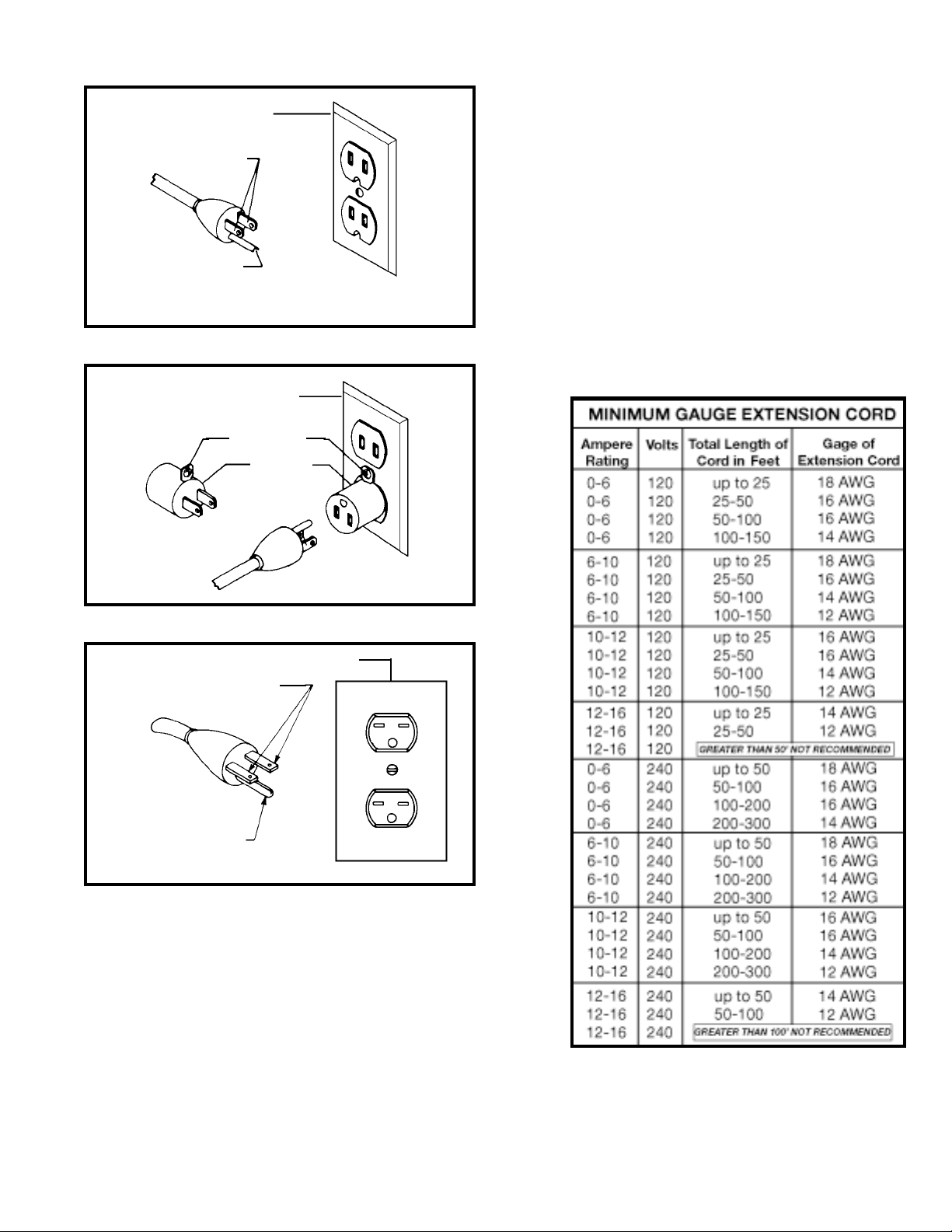
Fig. A
Fig. B
GROUNDED OUTLET BOX
CURRENT
CARRYING
PRONGS
GROUNDING BLADE
IS LONGEST OF THE 3 BLADES
GROUNDED OUTLET BOX
ADAPTER
Use proper extension cords. Make sure your extension
cord is in good condition and is a 3-wire extension cord
which has a 3-prong grounding type plug and a 3-pole
receptacle which will accept the tool’s plug. When using
an extension cord, be sure to use one heavy enough to
carry the current of the saw. An undersized cord will
cause a drop in line voltage, resulting in loss of power
and overheating. Fig. D, shows the correct gauge to use
depending on the cord length. If in doubt, use the next
heavier gauge. The smaller the gauge number, the heavier the cord.
Fig. D
EXTENSION CORDS
RECOMMENDED EXTENSION CORD SIZES FOR USE
WITH STATIONARY ELECTRIC TOOLS
FOREWORD
The Delta Model 70-200 Drill Press provides production capacity drilling and includes; 1 hp single phase 115/230 volt
induction motor, pulleys, belts, 0 - 5/8 capacity chuck, 45 degree tilt table L/R, rack and pinion table raising mechanism
and #3 Morse Taper spindle adaptor. A quick release motor mount makes changing the nine spindle speeds (150, 260,
300, 440, 490, 540, 1150, and 2200 rpm) fast and easy.
5
Fig. C
OPERATING INSTRUCTIONS
GROUNDED OUTLET BOX
GROUNDING BLADE
IS LONGEST OF THE 3 BLADES
CURRENT
CARRYING
PRONGS
GROUNDING
MEANS
Page 6
6
UNPACKING AND CLEANING
Carefully unpack the drill press and all loose items from the carton. Remove the protective coating from the
machined surfaces of the drill press and all loose items. This coating may be removed with a soft cloth moistened with kerosene. DO NOT USE ACETONE, GASOLINE, OR LACQUER THINNER FOR THIS PURPOSE.
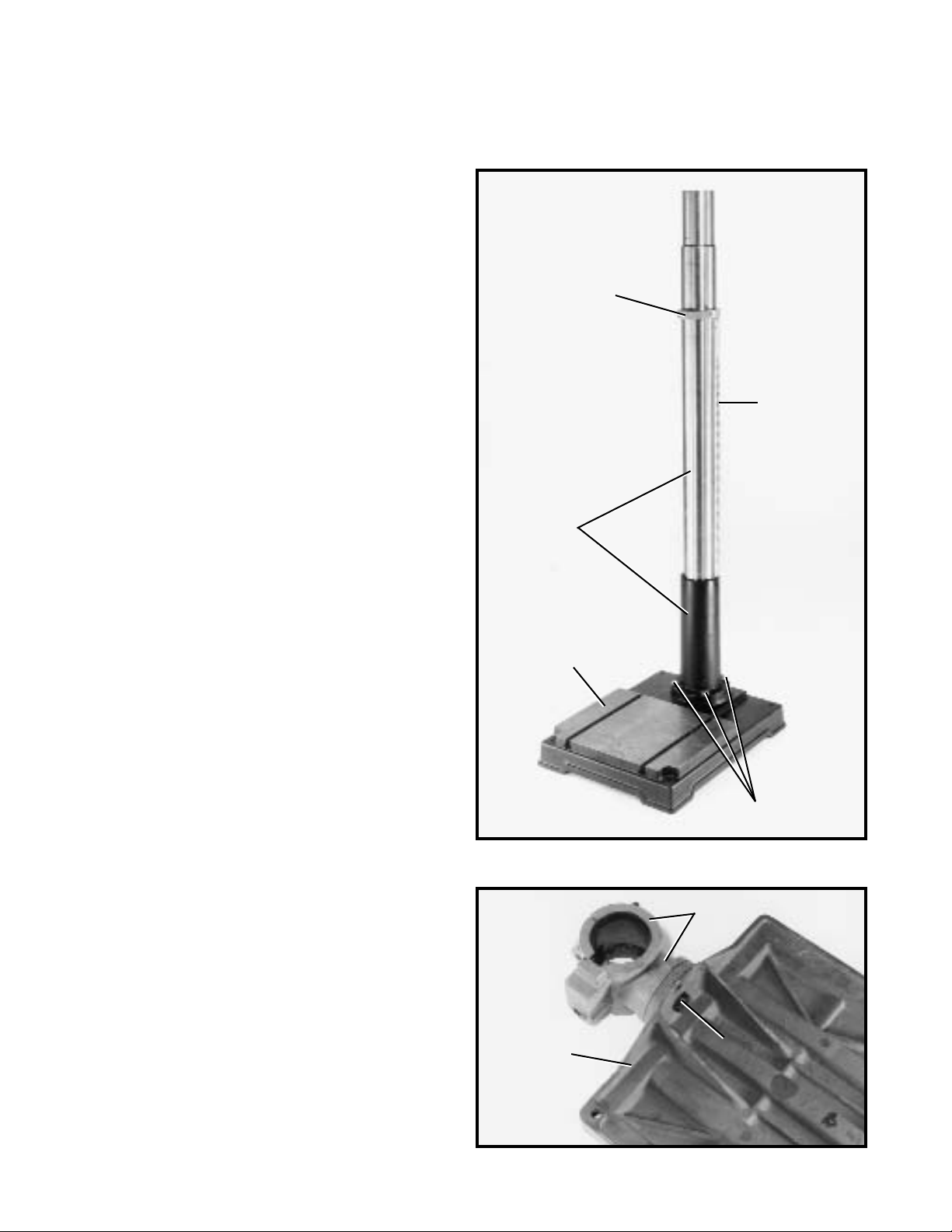
Fig. 2
Fig. 3
ASSEMBLING THE
DRILL PRESS
1. Assemble column (A) Fig. 2, to base (B) using four
M-12 x 45mm long hex head screws (three of which are
shown at [C]). Loosen set screw in collar (D) and remove
collar (D) and raising rack (E).
2. Remove bolt (F) Fig. 3, and remove table (G) from
table bracket (H).
H
G
F
B
C
A
E
D
Page 7

7
Fig. 4
3. Assemble worm gear (J) Fig. 4, to the inside of hole
(K) in table bracket (H).
4. Thread table lock lever (M) Fig. 4, into hole in table
bracket, as shown.
Fig. 5
Fig. 6
5. Place raising rack (E) Fig. 5, in position inside table
bracket (H) making sure gear on inside of table bracket
is engaged with teeth of raising rack.
6. Slide table bracket (H) Fig. 6, with raising rack (E)
onto column (A), as shown.
7. Engage bottom of rack (E) Fig. 6, with flange (L) on
column. Tighten table lock lever to lock table bracket (H)
to column.
M
K
H
J
H
E
E
H
A
L
Page 8

8
8. Reassemble collar (D) Fig. 7, which was removed in
STEP 1, to column. IMPORTANT: Bottom of collar (D)
MUST NOT be pushed all the way down onto top of rais-
ing rack (E). MAKE SURE top of raising rack (E) is under
bottom of collar (D) and that there is enough clearance to
allow rack (E) to rotate around the column. Then tighten set
screw (Q) being careful not to overtighten.
10. Assemble table raising and lowering handle (N) Fig.
10, to shaft on table bracket. Line up flat on shaft with
screw (O) and tighten screw (O).
Fig. 10
Fig. 7
Fig. 8
Fig. 9
9. Assemble table (G) Fig. 8, to table bracket (H) using
bolt (F). Line up hole (S) in table with hole in table bracket
and insert pin (P) Fig. 9.
D
Q
E
G
H
S
F
P
O
N
Page 9

9
Fig. 11
11. Place the drill press head on column, as shown. Line
up head with base and tighten two head locking screws
(R) Fig. 11.
12. Thread the three pinion wheel handles (Z) Fig. 12,
into the three threaded holes in the pinion shaft, as
shown.
13. Make certain the tapered hole in the bottom of the
spindle (T) Fig. 13, and the taper on the spindle adapter
(U) are clean and push the spindle adapter (U) up into
the spindle, making certain the tang (V) engages and
locks with the mating slot inside the spindle.
Fig. 12
Fig. 13
Fig. 14
Fig. 15
14. Make certain the bottom taper of the spindle
adapter (U) Fig. 14, and the tapered hole in the chuck
(W) are clean and push the chuck up onto the spindle
adapter (U) as far as it will go. NOTE: Household oven
cleaner can effectively remove any substance from the
spindle and chuck; however, carefully follow the manufacturer’s safety rules concerning its use.
15. Open the chuck jaws as wide as possible by turning
the chuck sleeve (X) Fig. 15.
16. Place a block of wood (Y) Fig. 15, on the drill press
table and lower the spindle until the chuck contacts the
piece of wood. Exert pressure to properly seat the
chuck.
CHUCK KEY
This drill press is provided with a self-ejecting type
chuck key. Use only this key or a duplicate. The use of
the self-ejecting chuck key ensures that the chuck key is
removed before the chuck is rotated.
R
Z
T
V
U
U
W
X
Y
Page 10

10
Fig. 16
FASTENING DRILL PRESS BASE
TO A SUPPORTING SURFACE
Fig. 17
Fig. 18
PERMANENT MOUNTING
If your drill press is to be used in one permanent location, the drill press base must be secured to the supporting surface with fasteners through the four mounting
holes, (A) Fig. 16, in the drill press base.
MOUNTING YOUR
DRILL PRESS TO A
PLYWOOD BASE
If you do not fasten your drill press in a permanent
manner, the drill press must be fastened to a plywood
mounting board to prevent the drill press from tipping
over during normal use. Use a good grade of plywood
with a minimum 3/4 thickness. Do not make the mounting board from particle board since particle board can
unexpectedly break.
1. Drill four 3/8 diameter holes (B) Fig. 17, corresponding to the mounting holes (A) Fig. 16, of the drill
press base in a 26 x 32 minimum size plywood board.
2. Fasten the drill press base to the mounting board
using the carriage bolts, nuts, and washers (C) Fig.17,
furnished with your drill press. The carriage bolt heads
must be countersunk such that the bolt heads are flush
with the bottom surface of the mounting board in order
to guarantee the proper stability.
3. When the drill press is mounted to the supporting
board, the board must extend a minimum of 3 beyond
each edge of the drill press base, as shown in Fig. 18.
4. The plywood base must be secured to the floor or
supporting surface if there is any tendency of the drill
press to vibrate, slide, or walk during normal operation.
A
B
B
26²Minimum
32
²
Minimum
3
²
Minimum
3²Minimum
C
Page 11

11
OPERATING CONTROLS AND ADJUSTMENTS
Fig. 23
START/STOP SWITCH
The switch is located on the front of the drill press head.
To start the machine, press the start button (A) Fig. 23,
and to stop the machine, press the stop button (B).
LOCKING SWITCH IN
THE “OFF” POSITION
IMPORTANT: When the machine is not in use, the
switch should be locked in the “OFF” position using a
padlock (C) Fig. 24, (with 3/16 diameter shackle)
through the two holes in the switch plate, as shown in
Fig. 24. NOTE: Padlock shown is available as accessory
Model 50-325.
Fig. 24
Fig. 25
Fig. 26
CHANGING SPINDLE
SPEEDS AND ADJUSTING
BELT TENSION
1. DISCONNECT THE DRILL PRESS FROM THE
POWER SOURCE.
2. Lift up the belt and pulley guard (A) Fig. 26.
3. Loosen the two lock knobs, one of which is shown
at (B) Fig. 26. The remaining lock knob is located on the
opposite side of the head casting.
4. Release belt tension by moving tension lever (C)
Fig. 26, forward.
5. Position the two belts (D) Fig. 26, on the desired
steps of the motor, center and spindle pulleys.
6. After the belts (D) Fig. 26, are positioned on the
desired steps of the motor, center and spindle pulleys,
move tension lever (C) to the rear until the belts (D) are
properly tensioned and tighten the two tension lock
knobs (B). The belts (D) should be just tight enough to
prevent slipping. Excessive tension will reduce the life of
the belts, pulleys and bearings. Correct tension is
obtained when the belts (D) can be flexed about 1 out
of line midway between the pulleys using light finger
pressure.
SPINDLE SPEEDS
Nine spindle speeds of 150, 260, 300, 440, 490, 540,
1150, 1550, and 2200 RPM are available with the 20
Drill Press. Fig. 25, illustrates which steps of the pulleys
the belts must be placed to obtain the nine speeds available.
SPINDLE CENTER MOTOR
440
300
150
1150
540
260
2200
1550
490
A
B
C
A
C
B
D
D
Page 12

12
Fig. 27
Fig. 28
Fig. 29
Fig. 30
DRILLING HOLES TO DEPTH
Where a number of holes are to be drilled to exactly the
same depth, a depth stop is provided in the pinion shaft
housing (A) Fig. 27, and is used as follows:
1. Loosen lock lever (B) Fig. 27, and rotate housing (A)
until the pointer (C) lines up with the depth indicated on
the English/Metric scale (D) that you want the spindle to
lower. Then tighten lock lever (B).
2. The spindle will then lower to the exact depth as
indicated on the scale (D) Fig. 27
ADJUSTING SPINDLE
RETURN SPRING
For the purpose of automatically returning the spindle
upward after a hole has been drilled, a spindle return
spring is provided in the spring housing (A) Fig. 28. This
spring has been properly adjusted at the factory and
should not be disturbed unless absolutely necessary. To
adjust the return spring, proceed as follows:
1. DISCONNECT THE DRILL PRESS FROM THE
POWER SOURCE.
2. Loosen the two nuts (B) Fig. 28, approximately onequarter inch. IMPORTANT: DO NOT REMOVE NUTS
(B) FROM SHAFT.
3. While FIRMLY holding spring housing (A) Fig. 28,
pull out housing and rotate it until the roll pin (C) is
engaged with the next notch on the housing. Turn the
housing counterclockwise to increase and clockwise to
decrease spring tension. Then tighten the two nuts (B)
to hold the housing in place. IMPORTANT: NUTS (B)
SHOULD NOT CONTACT SPRING HOUSING (A) WHEN
TIGHT.
TABLE ADJUSTMENTS
1. The table can be raised or lowered on the column by
loosening table clamp handle (A) Fig. 29, and turning the
table raising and lowering handle (B). After the table is at
the desired height, tighten handle (A).
2. The table can be tilted right or left by pulling out and
removing table alignment pin (C) Fig. 30, and loosening
table locking bolt (D). Tilt the table to the desired angle
and tighten bolt (D). A tilt scale and pointer are provided
on the table bracket casting to indicate the degree of tilt.
When returning table to the level position, replace table
alignment pin (C) Fig. 30. This will automatically position
the table surface at 90 degrees to the spindle.
C
D
B
C
A
D
B
A
C
B
A
Page 13

13
Fig. 31
OPERATION
Your Drill Press should be used with drill bits 5/8²or less in diameter.
The following directions will give the inexperienced operator a start on common drill press operations. Use
scrap material for practice to get a feel of the machine before attempting regular work.
IMPORTANT: When the workpiece is long enough, it should always be positioned on the table with one end
against the column, as shown in Fig. 32. This prevents the workpiece from rotating with the drill bit or cutting tool, causing damage to the workpiece or personal injury to the operator. If it is not possible to support
the workpiece against the column, the workpiece should always be fastened to the table using clamps or a
vise.
Fig. 32
REMOVING CHUCK
AND SPINDLE ADAPTER
If you desire to remove the chuck and spindle adapter,
lower spindle and rotate chuck until the slot in the
spindle lines up with the slot in the quill, as shown in
Fig. 31. Then insert tapered end of drift bar (A) into slot
(B) in quill and remove chuck and spindle adapter.
CORRECT DRILLING SPEEDS
Factors which determine the best speed to use in any drill press operations are: kind of material being
worked, size of hole, type of drill or other cutter, and quality of cut desired. The smaller the drill, the greater
the required RPM. In soft materials, the speed should be higher than for hard metals.
WARNING: Use the recommended speed for the drill press bit and workpiece material. As a guideline
for the speed to use for different drill diameters and materials, refer to the chart located on the inside
top cover of the drill press for your convenience.
B
A
Page 14

14
DRILLING METAL
Use clamps to hold the work when drilling in metal. The work should never be held in the bare hand;
the lips of the drill may seize the work at any time, especially when breaking through the stock. If the
workpiece is whirled out of the operator’s hand, he may be injured. In any case, the drill will be broken
when the work strikes the column.
The work must be clamped firmly while drilling; any tilting, twisting or shifting results not only in a rough
hole, but also increases drill breakage. For flat work, lay the piece on a wooden base and clamp it
firmly down against the table to prevent it from turning. If the piece is of irregular shape and cannot be
laid flat on the table, it should be securely blocked and clamped.
BORING IN WOOD
Twist drills, although intended for metal drilling, may also be used for boring holes in wood. However,
machine spur bits are generally preferred for working in wood; they cut a square bottom hole and are
designed for removal of wood chips. Do not use hand bits which have a screw tip; at drill press speeds
they turn into the wood so rapidly as to lift the work off the table and whirl it.
For through boring, line up the table so that the bit will enter the center hole to avoid damage. Scribe
a vertical line on the front of the column and a matchmark on the table bracket, so that the table can
be clamped in the center position at any height.
Feed slowly when the bit is about to cut through the wood to prevent splintering the bottom face. Use
a scrap piece of wood for a base block under the work. This helps to reduce splintering and protects
the point of the bit.
Page 15

NOTES
Page 16

Delta Building Trades and Home Shop Machinery
Two Year Limited Warranty
Delta will repair or replace, at its expense and at its option, any Delta machine, machine part, or machine accessory which
in normal use has proven to be defective in workmanship or material, provided that the customer returns the product prepaid to a Delta factory service center or authorized service station with proof of purchase of the product within two years
and provides Delta with reasonable opportunity to verify the alleged defect by inspection. Delta may require that electric
motors be returned prepaid to a motor manufacturer’s authorized station for inspection and repair or replacement. Delta
will not be responsible for any asserted defect which has resulted from normal wear, misuse, abuse or repair or alteration
made or specifically authorized by anyone other than an authorized Delta Service facility or representative. Under no circumstances will Delta be liable for incidental or consequential damages resulting from defective products. This warranty
is Delta’s sole warranty and sets forth the customer’s exclusive remedy, with respect to defective products; all other warranties, express or implied, whether of merchantability, fitness for purpose, or otherwise, are expressly disclaimed by Delta.
Printed in U.S.A.
PARTS, SERVICE OR WARRANTY ASSISTANCE
All Delta Machines and accessories are manufactured to high quality standards and are serviced by
a network of Porter-Cable
Delta Factory Service Centers and Delta Authorized Service Stations.
To obtain additional information regarding your Delta quality product or to obtain parts, service,
warranty assistance, or the location of the nearest service outlet, please call 1-800-223-7278 (In
Canada call 1-800-463-3582).
ACCESSORIES
A complete line of Delta accessories are available from your Delta Supplier, Porter-Cable Delta
Factory Service Centers, and Delta Authorized Service Stations. Please visit our Web Site
www.deltamachinery.com for a catalog or for the name of your nearest supplier.
WARNING: Since accessories, other than those offered by Delta, have not been tested with
this product, use of such accessories could be hazardous. For
safest operation, only Delta
recommended accessories should be used with this product.
Model No. 50-325 Solid Brass Padlock & Key
Model No. 17-985 Drill Press Safety Shield
Page 17

The following are trademarks of PORTER-CABLE DELTA Corporation (Las siguientes son marcas registradas de PORTER-CABLE S.A.):
BAMMER
®
, INNOVATION THAT WORKS®, JETSTREAM®, LASERLOC®, OMNIJIG®, POCKET CUTTER®, PORTA-BAND®, PORTA-PLANE®,
PORTER-CABLE
®
, QUICKSAND®, SANDTRAP®, SAW BOSS®, SPEED-BLOC®, SPEEDMATIC®, SPEEDTRONIC®, STAIR-EASE®, THE PRO-
FESSIONAL EDGE
®
, THE PROFESSIONAL SELECT®, TIGER CUB®, TIGER SAW®, TORQBUSTER®, WHISPER SERIES®, DURATRONIC™,
FLEX™, FRAME SAW™, MICRO-SET™, MORTEN™, NETWORK™, RIPTIDE™, TRU-MATCH™, WOODWORKER’S CHOICE™.
Trademarks noted with ® are registered in the United States Patent and Trademark Office and may also be registered in other countries.
Las Marcas Registradas con el signo de ® son registradas por la Oficina de Registros y Patentes de los Estados Unidos y también
pueden estar registradas en otros países.
PORTER-CABLE DELTA SERVICE CENTERS
(CENTROS DE SERVICIO DE PORTER-CABLE
DELTA)
Parts and Repair Service for Porter-Cable/Delta Power Tools are Available at These Locations
(Obtenga Refaccion de Partes o Servicio para su Herramienta en los Siguientes Centros de Porter-Cable Delta)
Authorized Service Stations are located in many large cities. Telephone 800-487-8665 or 901-541-6042 for assistance locating one.
Parts and accessories for Porter-Cable Delta products should be obtained by contacting any Porter-Cable Delta Distributor, Authorized
Service Center, or Porter-Cable Delta Factory Service Center. If you do not have access to any of these, call 888-848-5175 and you will
be directed to the nearest Porter-Cable Delta Factory Service Center. Las Estaciones de Servicio Autorizadas están ubicadas en muchas
grandes ciudades. Llame al 800-487-8665 ó al 901-541-6042 para obtener asistencia a fin de localizar una. Las piezas y los accesorios
para los productos Porter-Cable Delta deben obtenerse poniéndose en contacto con cualquier distribuidor Porter-Cable Delta, Centro
de Servicio Autorizado o Centro de Servicio de Fábrica Porter-Cable Delta. Si no tiene acceso a ninguna de estas opciones, llame al
888-848-5175 y le dirigirán al Centro de Servicio de Fábrica Porter-Cable Delta más cercano.
Printed in U.S.A.
CANADIAN PORTER-CABLE DELTA SERVICE CENTERS
ALBERTA
Bay 6, 2520-23rd St. N.E.
Calgary, Alberta
T2E 8L2
Phone: (403) 735-6166
Fax: (403) 735-6144
BRITISH COLUMBIA
8520 Baxter Place
Burnaby, B.C.
V5A 4T8
Phone: (604) 420-0102
Fax: (604) 420-3522
MANITOBA
1699 Dublin Avenue
Winnipeg, Manitoba
R3H 0H2
Phone: (204) 633-9259
Fax: (204) 632-1976
ONTARIO
505 Southgate Drive
Guelph, Ontario
N1H 6M7
Phone: (519) 836-2840
Fax: (519) 767-4131
QUÉBEC
1515 ave.
St-Jean Baptiste,
Québec, Québec
G2E 5E2
Phone: (418) 877-7112
Fax: (418) 877-7123
1447, Begin
St-Laurent, (Montréal),
Québec
H4R 1V8
Phone: (514) 336-8772
Fax: (514) 336-3505
ARIZONA
Tempe 85282 (Phoenix)
2400 West Southern Avenue
Suite 105
Phone: (602) 437-1200
Fax: (602) 437-2200
CALIFORNIA
Ontario 91761 (Los Angeles)
3949A East Guasti Road
Phone: (909) 390-5555
Fax: (909) 390-5554
San Leandro 94577 (Oakland)
3039 Teagarden Street
Phone: (510) 357-9762
Fax: (510) 357-7939
COLORADO
Denver 80216
5855 Stapleton Drive North
Suite A-140
Phone: (303) 370-6909
Fax: (303) 370-6969
FLORIDA
Davie 33314 (Miami)
4343 South State Rd. 7 (441)
Unit #107
Phone: (954) 321-6635
Fax: (954) 321-6638
Tampa 33609
4538 W. Kennedy Boulevard
Phone: (813) 877-9585
Fax: (813) 289-7948
GEORGIA
Forest Park 30297 (Atlanta)
5442 Frontage Road, Suite 112
Phone: (404) 608-0006
Fax: (404) 608-1123
ILLINOIS
Addison 60101 (Chicago)
311 Laura Drive
Phone: (630) 628-6100
Fax: (630) 628-0023
Woodridge 60517 (Chicago)
2033 West 75th Street
Phone: (630) 910-9200
Fax: (630) 910-0360
MARYLAND
Elkridge 21075 (Baltimore)
7397-102 Washington Blvd.
Phone: (410) 799-9394
Fax: (410) 799-9398
MASSACHUSETTS
Braintree 02185 (Boston)
719 Granite Street
Phone: (781) 848-9810
Fax: (781) 848-6759
Franklin 02038 (Boston)
Franklin Industrial Park
101E Constitution Blvd.
Phone: (508) 520-8802
Fax: (508) 528-8089
MICHIGAN
Madison Heights 48071 (Detroit)
30475 Stephenson Highway
Phone: (248) 597-5000
Fax: (248) 597-5004
MINNESOTA
Minneapolis 55429
4315 68th Avenue North
Phone: (612) 561-9080
Fax: (612) 561-0653
MISSOURI
North Kansas City 64116
1141 Swift Avenue
P.O. Box 12393
Phone: (816) 221-2070
Fax: (816) 221-2897
St. Louis 63119
7574 Watson Road
Phone: (314) 968-8950
Fax: (314) 968-2790
NEW YORK
Flushing 11365-1595 (N.Y.C.)
175-25 Horace Harding Expwy.
Phone: (718) 225-2040
Fax: (718) 423-9619
NORTH CAROLINA
Charlotte 28270
9129 Monroe Road, Suite 115
Phone: (704) 841-1176
Fax: (704) 708-4625
OHIO
Columbus 43214
4560 Indianola Avenue
Phone: (614) 263-0929
Fax: (614) 263-1238
Cleveland 44125
8001 Sweet Valley Drive
Unit #19
Phone: (216) 447-9030
Fax: (216) 447-3097
OREGON
Portland 97230
4916 NE 122 nd Ave.
Phone: (503) 252-0107
Fax: (503) 252-2123
PENNSYLVANIA
Willow Grove 19090
520 North York Road
Phone: (215) 658-1430
Fax: (215) 658-1433
TENNESSEE
Nashville 37214
2262 Lebanon Pike
Phone: (615) 882-0320
Fax: (615) 882-0051
TEXAS
Carroliton 75006 (Dallas)
1300 Interstate 35 N
Suite 112
Phone: (972) 446-2996
Fax: (972) 446-8157
Houston 77055
West 10 Business Center
1008 Wirt Road, Suite 120
Phone: (713) 682-0334
Fax: (713) 682-4867
WASHINGTON
Renton 98055 (Seattle)
268 Southwest 43rd Street
Phone: (425) 251-6680
Fax: (425) 251-9337
 Loading...