

Page 1

This appliance is compliant with the requirements of
directives 2004/108/EC (Electromagnetic Compatibility)
and 2006/95/EC (Low-Voltage Safety)
Because of changes in standards and equipment, the characteristics given in the text and the
illustrations provided in this document are not binding unless expressly confirmed
*2702305_Rev.1*
PROG
6
8101
4
16
TYBOX 610
Weekly programmable thermostat
Installation guide
DELTA DORE - Bonnemain
35270 COMBOURG - FRANCE
E-mail: deltadore@deltadore.com
1234567
i
0h 2 4 6 8 10 12 14 16 18 20 22 2 4
2 4
TYBOX
2 1
18 202224
AUTO
PROG
Page 2

- 2 -
Warnings Contents
• Carefully read these instructions prior to installation.
• The unit must be installed in compliance with current standards.
• Always switch off the mains before installing or servicing the unit.
• Do not attempt to repair the unit yourself; an after-sales ser vice is available.
• Check that the fastenings are suited to the surface to which the unit will be attached
(plasterboard, brick, etc.).
• The diagrams provided have been simplified for greater clarity. Protections and other
accessories required by standards are not illustrated.The UTE NF C15-100 standard
and industry best practices must be complied with. Connected or nearby units must
not generate excessive interference (directive 2004/108/EC).
- 3 -
Fitting the thermostat . . . . . . . . . . . . . . . . . . . . . . . . . . . . . . . . . . . . . . . . . . . . . . . . . 4
Connections . . . . . . . . . . . . . . . . . . . . . . . . . . . . . . . . . . . . . . . . . . . . . . . . . . . . . . . . . 7
Connecting a boiler with thermostat input . . . . . . . . . . . . . . . . . . . . . . . . . . . . . . . . . 7
Connecting a boiler without thermostat input . . . . . . . . . . . . . . . . . . . . . . . . . . . . . . 8
Controlling electric convectors . . . . . . . . . . . . . . . . . . . . . . . . . . . . . . . . . . . . . . . . . . 8
Controlling a heat pump . . . . . . . . . . . . . . . . . . . . . . . . . . . . . . . . . . . . . . . . . . . . . . . 9
Activation . . . . . . . . . . . . . . . . . . . . . . . . . . . . . . . . . . . . . . . . . . . . . . . . . . . . . . . . . . .10
Configuration . . . . . . . . . . . . . . . . . . . . . . . . . . . . . . . . . . . . . . . . . . . . . . . . . . . . . . . . 11
Correcting the temperature measured . . . . . . . . . . . . . . . . . . . . . . . . . . . . . . . . . . . . 12
Automatic mode temperature display option . . . . . . . . . . . . . . . . . . . . . . . . . . . . . . . 13
Setting the comfort temperature in heating mode . . . . . . . . . . . . . . . . . . . . . . . . . . . 13
Air conditioning function . . . . . . . . . . . . . . . . . . . . . . . . . . . . . . . . . . . . . . . . . . . . . . . 14
Circulator anti-seizing . . . . . . . . . . . . . . . . . . . . . . . . . . . . . . . . . . . . . . . . . . . . . . . . 15
Control time base . . . . . . . . . . . . . . . . . . . . . . . . . . . . . . . . . . . . . . . . . . . . . . . . . . . . 15
Restoring factory settings . . . . . . . . . . . . . . . . . . . . . . . . . . . . . . . . . . . . . . . . . . . . . 16
Summary table of configurations . . . . . . . . . . . . . . . . . . . . . . . . . . . . . . . . . . . . . . . 17
Technical features . . . . . . . . . . . . . . . . . . . . . . . . . . . . . . . . . . . . . . . . . . . . . . . . . . . . 18
Page 3
- 5 -- 4 -
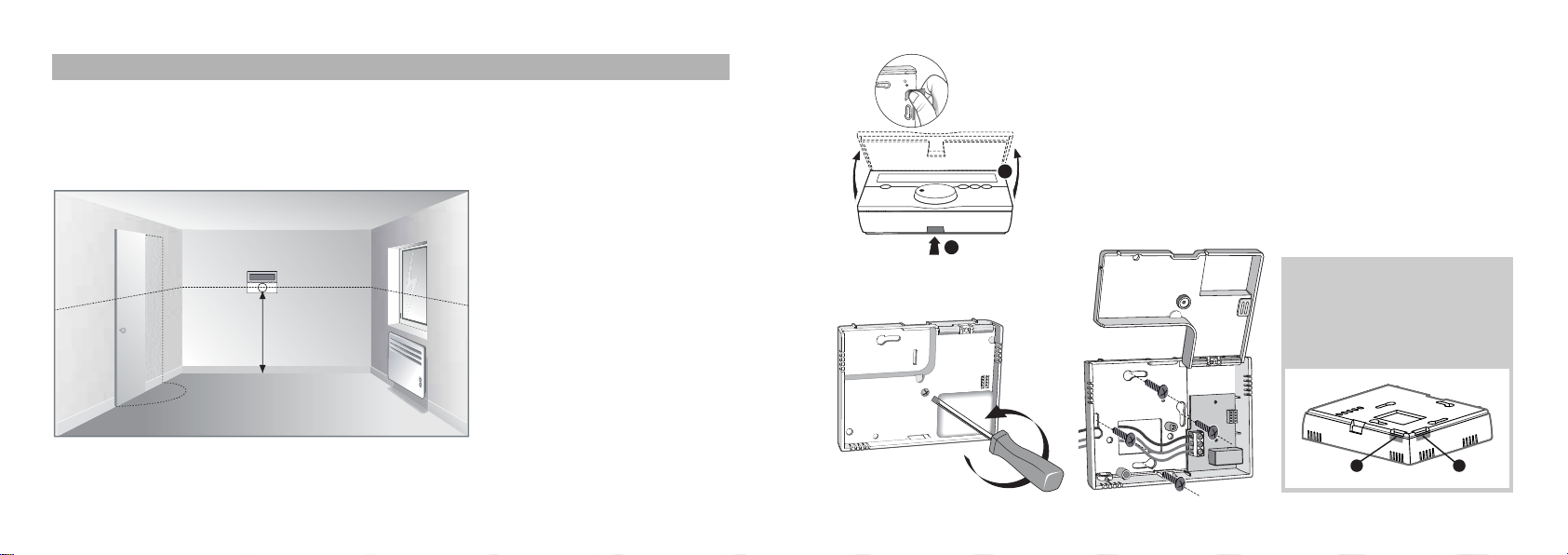
Fitting the thermostat
We recommend that you install your device:
- where there is easy access, such as a corridor, living room or entrance hall,
- on an interior wall at a height of 1.50m from the floor
Your appliance will also show you
the room temperature.
It is therefore recommended that
it be installed well removed from
any sources of heat (e.g. convectors, chimney) and draughts (e.g.
doors, windows).
• Remove the protective tab from the batteries.
• Open the thermostat housing by pressing on clip
➊
• Unscrew the locking screw on the protective cover of the
connecting terminal box.
• Mount the base using suitable screws and screw anchors or
fit into a flush-mounted box.
approx.
1.50 m
Partitions (mark
➌
) that can
be removed with pliers
enable connecting wires to
be used, if required.
2
1
3 3
Page 4

- 6 -
Connections
• Connect receiver terminals 1 and 3 to both terminals of the boiler thermostat input.
• If necessary, remove the shunt connecting the
two thermostat input terminals.
• If the boiler has a clock input, do not mistake it for
the thermostat input.
Connecting a boiler with thermostat input
- 7 -
• Connect the control wires
(see the section on
Connections) and screw
back in the locking screw
for the protective cover
Fitting the batteries
• Insert 2 LR03 1.5 V alkaline
batteries, making sure to
respect the battery polarities.
Never use rechargeable
batteries.
Use only alkaline batteries.
• Reposition the front
cover of the thermostat
and push until it clicks
into place
thermostat
boiler
boiler thermostat
input
do not confuse with
the clock input (on
some boiler models)
wires to be
connected to the
thermostat
remove the
shunt
Example of a boiler
terminal box
Click
1
2
3
Page 5

- 9 -
Controlling a heat pump
Select cabling that is suitable for your heat pump or refer directly to the manufacturer's
specifications.
Controlling electric convectors
To control electrical convectors, you MUST
use a power contact switch that is suitable
for the total power to be controlled.
This power contactor switch must be fitted
into the electrical switchboard of your home.
- 8 -
Connecting a boiler without thermostat
input
If the boiler does not have a thermostat
input, you can directly control the circulator which is located next to the boiler (the
pump enabling circulation of the hot water
into the radiators).
- Directly control the power supply to the
circulator using the thermostat.
thermostat
circulator
mains power
230 V/50 Hz
mains power
230 V/50 Hz
thermostat
power supply of
the contact
switch coil
contact switch (not supplied)
fitted in the electrical
switchboard
convector(s)
Heat pump
with thermostat input
and summer / winter Input
Heat pump
with thermostat heat input
and thermostat cool input
Heat pump
with thermostat input
and Summer / winter switch
Hydraulic kit
Hydraulic kit
Hydraulic kit
Underfloor
heating
output
Summer /
winter switch
Underfloor
heating
output
Underfloor
heating
output
Summer /
winter switch
Geothermal OR Air source Geothermal OR Air source Geothermal OR Air source
Thermostat
input
Thermostat
input
Summer /
winter switch
Summer /
winter Input
Thermostat
heat input
Commun
Thermostat
cool input
winterSummer
1
2
3
L
N
L
L
N
N
1
2
3
1
2
3
1
2
3
1
2
3
Page 6

- 11 -
Configuration
To access the configuration menus, turn the knob to the position marked
Press OK to access menu CF01
The reference number of your device is displayed as well as the version number
- 10 -
Activation
Turn the knob to the position
The day numbers flash.
• Press + or - to set the day, then
OK to confirm and go to the next
setting.
Repeat these steps to set the hours and minutes.
To exit the “time setting” mode, turn the selector knob.
Days
Hours Minutes
(1: Monday…
7: Sunday)
Unit
reference
number
Unit version
(e.g.: 1.00)
Page 7

- 13-
Automatic mode temperature display option
Enter your desired setting using the + or - buttons.
Press OK to confirm and move on to menu CF03
Setting the comfort temperature in heating mode
Enter your desired setting using the + or - buttons.
Press OK to confirm and move on to menu CF04
- 12 -
Correcting the temperature measured
IMPORTANT: In order to change this setting, the unit has to have been running for at
least 2 hours beforehand.
If there is a difference between the actual temperature (taken with a thermometer) and the
temperature measured and displayed by the unit, the CF01 function can be used to compensate for the difference by adjusting the sensor's readings.
Example:
If the temperature displayed by the unit
is 19°C and the temperature measured
is 20°C, add 1°C to the display
then confirm by pressing OK.
Enter your desired setting using the + or - buttons
Press OK to confirm and move on to menu CF02
CF0 1
Correction possible from -4°C to + 4°C in increments of 0.1°C.
Press the + or - buttons to make changes, and confirm with the OK
button to move on to the next setting
CF02
0
Continuous set-point temperature display (by default).
With this option, press i to display the room temperature.
1
Continuous room temperature display.
With this option, press i to display the set-point temperature.
CF03
0
Comfort temperature set by the TYBOX (by default)
1
Comfort temperatures set by each radiator
or convector. In this option the screen displays ConF.
Page 8

- 15 -
If your thermostat controls a circulator, set the value of the CF05 menu to equal 1.
Circulator anti-seizing
Control time base
Select the time base recommended for your type of installation
Enter your desired setting using the + or - buttons
Press OK to confirm
Enter your desired setting using the + or - buttons
Press OK to confirm and move on to menu CF06
- 14 -
With thermostatic valve electric heating or hot water heaters, the Comfort temperature can
be provided by adjusting the thermostat of each radiator.In this case, only the Economy
and Frost Protection temperatures are set by the TYBOX.
Air conditioning function
If you have a reversible heating / cooling system, change the setting on the CF04 menu to
equal 1.You are now authorised to switch the Tybox between heating and cooling modes.
(see the section on "Changing the heating / cooling mode")
Enter your desired setting using the + or - buttons
Press OK to confirm and move on to menu CF05
Switching the value on menu CF04 to 0 is only possible when the TYBOX is in heating
mode
CF04
0
Air-conditioning function not authorised. (by default)
1
Air-conditioning function authorised.
CF05
0
Anti-seizing off (by default)
1
Anti-seizing enabled (circulator operates for 1 minute
every 24 hours)
CF06
0
15 min (recommended for controlling convectors or traditional
radiators). (by default)
1
30 min (recommended for controlling heat pumps, depending
on the model)
2
45 min (recommended for controlling heat pumps, depending
on the model)
Page 9

- 17 -
Summary table of configurations
CF01
Correction of the temperature measured
by -4°C to +4°C in increments of 0.1°C (0 by default).
CF02
Automatic mode temperature display option
0 = Continuous set-point temperature display (by default)
1 = Room temperature display
CF03
Control of the Comfort temperature in heating mode
0 = controlled by the Tybox (by default) 1 = by each radiator or convector
CF04
Air conditioning function
0 = Not authorised (by default) 1 = Authorised
CF05
Circulator anti-seizing
0 = inactive (by default) 1 = active
CF06
Control time base
0 = 15 minutes (by default) 1 = 30 minutes 2 = 45 minutes
- 16 -
Restoring factory settings
Turn the knob to the position
Press the left button for 10 seconds
Press OK to confirm or C to cancel.
Return to the shutdown mode display.
You can execute a general reset command to return to the factory settings:
- the default configuration settings
- the default set-point temperatures, Heating Mode - Comfort: 19°C, Economy: 16°C
Cooling mode - Comfort: 23°C, Economy: 28°C
- the default schedule (Comfort mode from 6am to 11pm).
10 seconds
Cancel
Confirmation
Page 10

- 18 -
Technical features
• Power supplied by two LR03 or AAA 1.5 V alkaline batteries.
“No rechargeable batteries”
• 1 2A / 230V power outlet
• Dimensions: 111 x 84 x 28.5 mm
• Protection rating: IP 30
• Installation in an environment with normal pollution levels
• Storage temperature: -10°C to +70°C
• Operating temperature: 0°C to +40°C
• Type 1C brownout
• Class II insulation
• Clock save:30 seconds
Notes
 Loading...