

Page 1
Characteristics
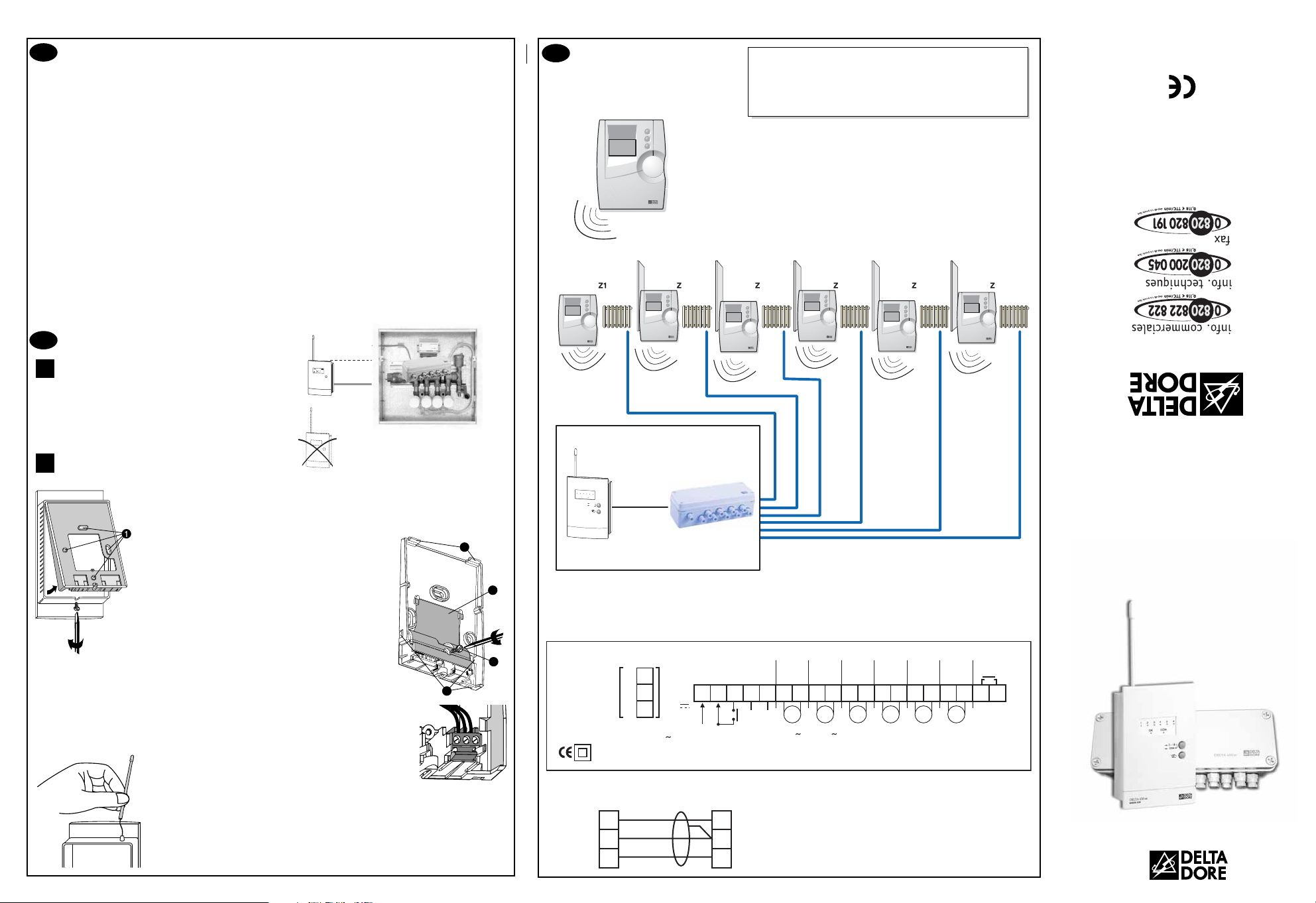
DELTA 600 is made up of a receiver unit and a technical control unit.
Installation
Positioning options
The receiver must be placed in a high position.
The receiver antenna must be kept away from
conductors (electrical cables, electrical switchboard,
metallic surface).
Mountings
To mount the unit on the wall, it must be separated from its base.
To do this, unscrew the clamp screw as shown opposite.
Once separated from the unit, the base must be fixed to the wall with screws and plugs or
on a flush-mounted box (distance between centres 60 mm) using the holes labelled ➊.
To do this:
Unscrew the screw ➋
to remove the terminal box cover ➎.
Temporary partitions, labelled ➌, are provided
to make room for the connection wire if needed.
- Connect the connection wires (see section 3).
- Replace the terminal box cover and secure it with
the screw ➋.
Position the unit on the support by first inserting the tabs ➍, then by pushing it until it is
securely fastened to the support.
3.5 Mounting the antenna
Slide the flexible wire into the tube, then push the tube in
as far as it will go.
Technical unit
• 230 V, 50 Hz power supply, ±10%
• Class II insulation
• Power consumption: 4 VA
• 6 power-supplied operating contact output, 1A,
250V (valves)
• 1 auxiliary contact output, 5 A, 250 V
(burner, circulator, etc.)
• 1 fixed-wire connection bus with the receiver unit
(DELTA 600 BR)
• Dimensions: 80 x 230 x 65 mm
Receiver unit
• TBTS 24 Volt power supply provided by the
technical unit
• Fixed-wire connection bus with the technical unit
(SYT 6/10-type 2 pair telephone cable with shield
and continuity wire, 5 metres max.)
• Receiver frequency: 868 MHz (standard 300 220)
• Radio range 100 to 300 metres outside depending
on the linked equipment (the range can be altered
depending on the installation conditions and the
electromagnetic environment)
• Flexible antenna that slides into its support
• 2 buttons to configure outputs
• Wall mounted
• Dimensions: 128 x 85 x 31 mm
• Protection index: IP 30
• Operating temperature: 0 to +40°C
• Storage temperature: -10 to +70°C
1
2
2700621 Rev.3
Connections
Switch off the mains power before
handling the device.
3
The diagrams provided are simplified for greater clarity.
The protective devices and other accessories required by the standards are
not illustrated.
- Standard UTE C15-100 and good practice must be complied with.
- Connected or nearby equipment must not generate excessive
interference (directive 89/336/EEC).
Technical unit connecting terminal box
Connection between the receiver unit and the technical unit
l
Fixed-wire connection bus (SYT 6/10-type 2 pair
telephone cable with shield and continuity wire,
5 metres max.)
The continuity wire is connected to terminal 2 of
the technical unit.
Product compliant with the requirements of directives
89/336/EEC (electromagnetic compatibility) and 73/23/EEC
modified 93/68/EEC (low voltage)
DELTA 600
Control receiver for 6-channel
heating/air-conditioning
control system
Receiver
YES
NO
Option 1
Centralized
control
Delta 600 COM
Programming
zone
Programming
zone
2
Delta 600 TH
Transmitters
Delta 600
Programming
zone
3
Programming
zone
456
Programming
zone
Programming
Delta 600 TH
Transmitters
zone
pro.deltadore.com
E-mail : deltadore@deltadore.com
DELTA DORE TALCO - Bonnemain - 35270 COMBOURG
Technical unit
1
2
3
456
OK
ZS
....
16
ZS
4
Receiver unit
Solenoid
valve control
5
2
To
8
3
receiver
unit
2721159 Rev. 2
Power supply 230V 4VA
1
2
7
3
6
50Hz / 60 Hz
BUS
24V
N
L
Change-over
power supply
1 A
1 A
1 A
1 A
Max.
Max.
Max.
Max.
1 A
Max.
7854 6 9 10111213141516171819202122
V1 V2 V3 V4 V5 V6
Val ve
24 V to 230 V
1 A
Max.
5 A
Max.
Auxiliary
contact
(Burner,
circulator,
etc.)
Receiver
unit
8
7
6
1
2
3
Technica
unit
Page 2
Starting up
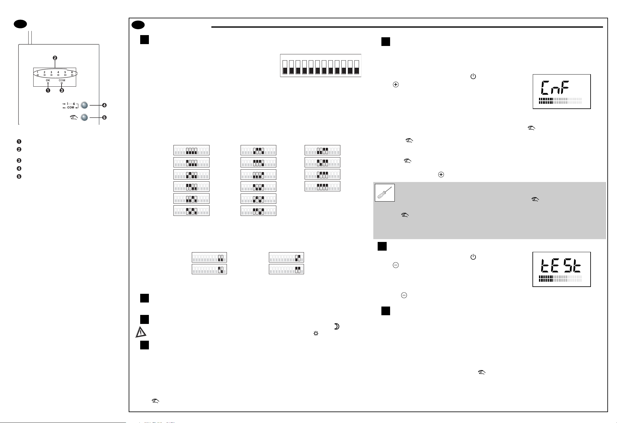
Configuring the technical unit outputs
Remove the receiver unit from its base to access the configuration switches.
SW1: Type of relay control (1A outputs)
ON: Normally closed OFF: Normally open
This selection affects all 6 relay outputs simultaneously.
SW2: Burner or circulator selection (output 5A)
ON: Circulator (activates SW3 function) OFF: Burner
SW3: Anti-seizing function of the circulator (active if the SW2 selection is ON)
ON: Anti-seizing OFF: No anti-seizing
SW4: Keep last valve controlled open
(for constant water circulation in the hydraulic circuit).
ON: Keep last valve controlled open OFF: Authorizes closure of last valve controlled
SW5 to SW8: Solenoid valve opening times
Selection to be made according to the solenoid valves' technical characteristics.
SW9: Control time base
ON: 10 minutes (recommended for air-flow systems)
OFF: 20 minutes (best for hot-water radiant floors)
SW10 to SW11: Limit the cooling operation percentage
Limit according to the installation's cooling over-power.
SSW12: Not used
Technical control unit operation
LThe auxiliary contact is closed when one of the transmitters is in need of heat or cold.
Cooling mode operation (air-flow system)
When change-over is activated (Cooling mode), the Economy set-point temperature
on the thermostats must be higher than the Comfort set-point temperature .
Radio receiver operation
The 2 Heating and Cooling controls are calculated simultaneously. The LEDs on the receiver unit's front
side allow either Heating or Cooling controls to be viewed.
Selection method:
from normal display, press the 2 buttons for 5 sec. (the 6 LEDs flash quickly
indicating "control view selection" mode):
• for heating periods (change-over open), use the browsing button “1...6, COM” to select the red LED
(Com).
The unit displays the Heating control.
• for cooling periods (change-over closed), use the browsing button “1...6, COM” to select the green
LED (OK).
The unit displays the Cooling control.
Use the button to exit this mode (automatic exit after 2 min. of inactivity).
Radio configuration / reconfiguration
Configuration mode lets you couple a transmitter (Thermostat Delta 600 TH, Delta 600 COM centralized
control) with the Delta 600 BT receiver (no conflict possible with neighbouring installations). It is also used
to check the radio transmission.
➊ On the transmitter, turn the knob to the position.
➋ Press (~3 sec.) until CnF is displayed.
The transmitter sends its information to the receiver.
➌ On the receiver, push “1...6, COM” repeatedly until the LED of
the relative channel flashes.
• If the green LED (OK) is on steady, the receiver channel is already configured.
To reconfigure it (with another transmitter, for example), press the button for 10 sec. until the
green "OK" LED flashes slowly, then release it.
Press the button again.
The green "OK" LED comes on steady; the receiver channel has been "reconfigured".
• If the green LED (OK) is flashing slowly, the receiver channel is not configured.
Press the button.
The green "OK" LED comes on steady. The receiver channel is configured.
➍ On the transmitter, press to exit configuration mode.
Radio transmission check
➊ On the transmitter, turn the knob to the position.
➋ Press (~3 sec.) until tESt is displayed.
The transmitter sends its information to the receiver.
➌ Transmission is correct if, on the receiver, the "OK" LED and
“the LED of the relative channel” flash together.
➍ Press the button to exit the radio transmission test mode.
Problems?
A channel's red LED flashes (the receiver has not received information from the transmitter of the
relevant channel for more than an hour).
1) Check the transmitter batteries.
2) Go to transmission test mode.
- If the "OK" LED and "the LED of the relative channel" are not flashing together each time
information is received, move the transmitter.
- If the problem persists, reconfigure the units.
Note:
In the event of malfunction, pressing the button on the receiver changes the status of the
selected channel (exemption) until the next transmission from the thermostat (which continues to have
priority). For an override, the red LED flashes.
5.7
5.6
5.5
5.4
5.3
5.2
5.1
5
Description
The
Delta 600
control receiver is made up of 2
units:
- a receiver unit that receives information from
the transmitters (Delta 600 TH programmable
thermostats, Delta 600 COM centralized
control) by radio waves
- a technical unit, connected to the receiver unit
by a fixed-wire bus, which acts as a power
interface for controlling the installation's
valves.
Delta 600
will manage up to 6 hot-water heating or
air-conditioning outputs.
Delta 600
is designed for:
•
hot-water heating (underfloor or radiators)
• air-flow air-conditioning
• cooling floors equipped with dewpoint control
2 operating modes:
•
Current mode:
- Channel status display
- Display of the presence or absence of a
centralized control
•
Configuration mode:
- Display of whether or not a channel is
configured
- Manual activation of the channels in case of
a fault
Because of changes in standards and equipment, the characteristics given
in the text and the illustrations of this document are not binding unless
confirmed by Delta Dore.
4
Unconfiguring a channel
➊ To select a channel to unconfigure,
press “1...6, COM” repeatedly on the
receiver until the LED of the relevant
channel flashes.
➋ Hold the button down until the green "OK"
LED flashes (~30 sec.).
➌ Press the “1...6, COM” repeatedly until you exit
the mode.
Unconfiguring all channels
On the receiver, from the current operating
mode, press the button and hold it down until
the green "OK" LED flashes (~60 sec.).
The unit is now unconfigured.
Normal operation LED
Control status of the programmable
radio thermostats (Delta 600 TH)
Presence of the Delta 600 COM control unit
Scrolling button
Configuration button
ON
123456789101112
Valve opening delay
ON
0 sec.
123456789101112
ON
30 sec.
123456789101112
ON
1min.
123456789101112
1min. 30s.
2min. sec.
ON
123456789101112
ON
2min.
123456789101112
ON
123456789101112
3min.
3min. 30sec.
4min.
4min. 30sec.
5min.
5min. 30sec.
ON
123456789101112
ON
123456789101112
ON
123456789101112
ON
123456789101112
ON
123456789101112
ON
123456789101112
6min. 30sec.
7min. 30sec.
ON
6min.
123456789101112
ON
123456789101112
ON
7min.
123456789101112
ON
123456789101112
56789101112
No limit
75% limit
ON
12345678910 11 12
ON
12345678910 11 12
50% limit
25% limit
ON
12345678910 11 12
ON
12345678910 11 12
Page 3

Characteristics
• Runs on two LR03-type 1.5 V alkaline batteries
(autonomy greater than 1 year)
• Battery level indicator
• Operating mode selector knob (7 positions)
• Choice between 3 continuous temperatures:
Frost protection, Economy, Comfort
and 1 customizable program per day
• The 3 set-point temperatures can be adjusted
from:
5° to 30°C for Economy and Comfort,
5° to 15°C for Frost Protection
• Built-in proportional control (category B), time
basis: 15 min.
• Stand-by mode
• 868 MHz transmission frequency
(300 220 standard)
• Radio range 100 to 300 metres outside
depending on the linked equipment (the range
can be altered depending on the installation
conditions and the electromagnetic environment)
• Addressing: 65536 combinations
• Digital display
• Room unit: 126 x 85 x 31 mm
• Wall-mounted or on base
• Protection index: IP 30
• Class III insulation
Installer commissioning
Installation
2.1 Positioning options
2.1.1 Radio transmission
The thermostat must be positioned correctly.
In dwellings, the propagation of radio waves is reflected
and attenuated by the structures encountered.
We recommend that you check radio transmission
quality using the radio transmission test mode (§ 3.4).
2.1.2 Measuring temperature
Place the unit in a room whose temperature represents
the mean temperature in your dwelling. The recommended
height is 1.5 m; it should be accessible and away from
heat sources (fireplace, sunlight) and from draughts
(window, door).
If the thermostat is on its foldaway base, it can be used as
a genuine heating remote control and taken with you from
room to room.
1
2
3
➃ On the receiver, press “1...6, COM” repeatedly until
the LED of the relevant channel flashes.
• If the green LED (OK) is flashing slowly,
the receiver channel is not configured.
Press the button.
The green "OK" LED comes on steady. The receiver
channel is configured.
• If the green LED (OK) is on steady, the receiver
channel is already configured.
To reconfigure it, press the button for 10 sec.
until the green "OK" LED flashes slowly, then release
it.
Press the button once again.
The green "OK" LED comes on steady. The receiver
channel is "reconfigured".
→ On the transmitter, press to exit configuration
mode.
3.1 Fitting batteries
The unit is powered by 2 LR03 or AAA-type 1.5 V
alkaline batteries.
See user guide overleaf (§ 5.1).
3.2 Time setting
See user guide overleaf (§ 5.2).
3.3 Configuration / Reconfiguration
For each receiver output there is a transmitter.
The configuration mode is used to couple the receiver
output with a transmitter (no conflict possible with
other outputs). It is also used to check the radio
transmission.
Associating a receiver output with a transmitter
Turn the knob on the transmitter to the position.
➀ Press the button (3 sec.) until CnF is displayed.
The transmitter is sending its information to
the receiver.
3.4 Radio transmission check
On the transmitter, turn the knob to the position.
➀ Press the button (~3 sec.)
until the following is displayed:
The transmitter is sending
its information to the
receiver.
➃ Transmission is correct if, on the receiver, the "OK"
LED and “the LED of the relevant channel” flash
together.
→ Press the button to exit radio transmission test
mode.
3.5 Problems?
On the receiver, a channel's red LED flashes
(the receiver has not received information from
the transmitter of the relevant channel for more
than an hour).
1) Check the transmitter batteries.
2) Go to transmission test mode.
- If the "OK" LED and “the LED of the relevant
channel” are not flashing together each time
information is received, move the transmitter.
- If the problem persists, reconfigure the units.
Note:
In the event of malfunction, pressing
the button on the receiver changes the status
of the selected channel (exemption) until the next
transmission from the thermostat (which continues
to have priority). For an override, the red LED flashes.
2.2 Mounting
2.2.1 Wall-mount (preferred)
To mount the unit on the wall, it
must be separated from its base.
Once separated from the case,
the support must be fixed to the wall
with screws and plugs or on a
flush-mounted box (distance
between centres 60 mm).
2.2.2 Using the foldaway base (option)
Using the support provided,
you can place the transmitter
on an item of furniture or a table,
remembering to adhere to
the conditions for transmission
and thermal location.
DELTA 600 TH
Installation . Installation . Installation . Installation . Installation .Installation . Installation . Installation . Installation . Installation . Installation .
1.50 m
Min. 20 cm
Page 4

2700620 Rev.2_GB
Use . Use . Use . Use . Use . Use . Use . Use . Use . Use . Use . Use . Use . Use . Use . Use . Use . Use . Use . Use . Use . Use . Use . Use .
Temperatures
6.1 Setting the Frost Protection temperature
When starting up: Frost Protection = 7°C
Turn the knob to the position.
➀ Press the or buttons.
Temperature selection (5 to 15°C)
6.2 Setting the Economy temperature
When starting up: Economy = 16°C.
Turn the knob to the position.
➀ Press the or buttons.
Temperature selection (5 to 30°C)
IMPORTANT: In air conditioning mode, the economy
set-point temperature must be higher than the Comfort
set-point temperature.
6.3 Setting the Economy temperature
Default setting: Comfort = 19°C.
Turn the knob to the position.
➀ Press the or buttons.
Temperature selection (5 to 30°C)
6.4 Viewing the measured temperature
Press button.
The temperature of the room
is displayed.
Set the daily program
There are 4 preset programs.
You can select one of them
by turning the knob.
Continuous Frost
Protection (adjustable
from 5°C to 15°C)
Continuous Economy
mode (adjustable from
5°C to 30°C)
Permanent comfort
(adjustable from 5°C
to 30°C)
By default, Comfort
from 6:00 a.m. to
11:00 p.m. throughout
the week.
This program can be modified.
User start-up
5.1 Fitting batteries
Two LR03-type or AAA 1.5V alkaline batteries
(autonomy >1 year).
"No rechargeable batteries"
.
To install them, remove the unit from its base, insert
the batteries, being careful to put them in the correct
direction, then return the unit to its base.
Replacing batteries:
If the low battery LED comes on, do not leave the
flat batteries in the unit (the guarantee does not cover
damage caused by leakage from batteries).
You have approximately 1 minute to insert the new
batteries before the time you have set is erased.
The programs remain saved no matter what.
Presentation
5.2 Time setting
Turn the knob to the position.
Set the time and day by pressing and .
Each time you pass 24:00 you
change the day.
Press and release
Changes in 1-minute steps
Press and hold
Fast forward
5
7
6
4
Heating shutdown /
Standby mode
Switching to standby for operation outside heating
periods.
Turn the knob to the position.
The unit displays 4 dashes.
Modifying and saving your program
Turn the knob to PROG
The temperature display goes off.
The program assigned to the 1st day appears.
The 1st time slot flashes on and off.
➀ Press for 1 Comfort hour or for 1 Economy hour
(goes to next time slot).
Repeat the operation for each time slot.
➃ You must press to confirm and go to the next day
Repeat operations ➀ and ➃ for
each day
.
→ When you have finished programming, turn the knob to
AUTO.
For the , and AUTO modes, the displayed
temperature is the set-point temperature for the current
time slot.
E.g.: Day 3, it is 8:15 p.m
.
The relevant time slot flashes.
The comfort temperature
is requested and its value
is displayed.
or
Day 3, it is 4:20 a.m
.
The Economy set-point
temperature is displayed.
8
Because of changes in standards and equipment, the characteristics given
in the text and the illustrations of this document are not binding unless
confirmed by Delta Dore.
DELTA 600 TH
Wireless room thermostat
with one-week programming
Ref. 6000015
This appliance complies with the requirements of the directive
R&TTE1999/5/CE
OK
Current day
Temperature display
Battery level indicator
Daily program profile
( = Comfort, = Economy)
Modification buttons
Display of the measured
temperature or validation
in programming mode
6
Knob selection mark
7
Operating mode selector
knob (7 positions)
8
1
2
3
4
5
6
7
pro.deltadore.com
E-mail : deltadore@deltadore.com
DELTA DORE TALCO - Bonnemain - 35270 COMBOURG
Diagnosis / Solutions
Nothing appears
on the screen.
The whole display
is flashing.
The symbol appears.
No power supply.
Change the batteries or check
their polarity (correctly fitted).
The thermostat has just
been switched on.
Check the clock and the
temperatures and adjust them
if necessary, otherwise press
any button.
The batteries are low.
Change the batteries.
A
U
T
O
1
2
3
4
5
6
7
1
2
3
4
5
6
7
0h 2 4 6 8 10 12 1416 18 20 22 24
1
2
3
4
5
6
7
0h 2 4 6 81012141618202224
1
2
3
4
5
6
7
0h 2 4 6 81012141618202224
P
R
O
G
1
2
3
4
5
6
7
0h 2 4 6 8 10 12 1416 18 20 22 24
1
2
3
4
5
6
7
0h 2 4 6 8 10 12 1416 18 20 22 24
Page 5

Characteristics
• Runs on two LR03-type 1.5 V alkaline batteries
(autonomy greater than 1 year)
• Class III insulation
• Battery level indicator
• Operating mode selector knob (5 positions)
• Choice between 5 operating modes:
Frost protection, Economy, Comfort, Shutdown
or Auto
• Long absence adjustable from 1 to 99 days
• Transmission frequency 868 MHz:
(I-ETS 300 220 standard)
• Radio range: 100 to 300 metres outside
depending on the equipment associated
(the range can be altered depending on the
installation conditions and the electromagnetic
environment)
• Addressing: 65536 combinations
• Digital display
• Room unit: 128 x 85 x 31 mm
• Wall-mounted or on base
• Protection index: IP 30
• Operating temperature: 0 to +40°C
• Storage temperature: -10°C to +70°C
Installer commissioning
3.1 Fitting batteries
Two LR03-type or AAA 1.5V alkaline batteries
(autonomy >1 year).
"No rechargeable batteries".
To install them, remove the unit from its base, insert
the batteries, being careful to put them in the correct
direction, then return the unit to its base.
Replacing batteries:
If the low battery LED comes on, do not leave
the flat batteries in the unit (the guarantee does not
cover damage caused by leakage from batteries).
3.2 Configuration / Reconfiguration
Configuration mode lets you couple the Delta 600 COM
control unit with the Delta 600 BT receiver (no conflict
possible with neighbouring installations).
It is also used to check the radio transmission.
Installation
2.1 Positioning options
The thermostat must be positioned correctly.
In dwellings, the propagation of radio waves is reflected
and attenuated by the structures encountered.
We recommend that you check radio transmission
quality using the radio transmission test mode (§ 3.4).
2.2 Mounting
2.2.1 Wall-mount (preferred)
To mount the unit on the wall, it must
be separated from its base.
Once separated from the case,
the support must be fixed to
the wall with screws and plugs or
on a flush-mounted box (distance
between centres 60 mm).
1
2
3
Turn the knob on the Delta 600 COM control unit to
the position
➀ Press (~3 sec.) until CnF is displayed.
The control unit sends
its information to the
receiver.
➃ On the receiver, push “1...6, COM” repeatedly until
the “COM” LED flashes.
• If the green LED (OK) is flashing slowly, the
receiver's COM channel is not configured.
Press the button.
The green "OK" LED comes on steady.
The receiver's COM channel is configured.
• If the green LED (OK) is on steady, the receiver's
COM channel is already configured.
To reconfigure it (with another control unit, for
example), press the button for 10 sec. until
the green "OK" LED flashes slowly, then release it.
Press the button again.
The green "OK" LED comes on steady; the
receiver's COM channel has been "reconfigured".
→ Press to exit from configuration mode.
3.4 Radio transmission check
On the control unit, turn the knob to the position.
➀ Press (~3 sec.)
until tESt is displayed.
The transmitter sends
its information to
the receiver.
➃ Transmission is correct if, on the receiver, the "OK"
and “COM” LED flash together.
→ Press the button to exit the radio transmission test
mode.
3.5 Problems?
On the receiver, the “COM” LED flashes (the receiver
has not received information from the transmitter of
the relevant channel for more than an hour).
1) Check the transmitter batteries.
2) Go to transmission test mode.
- If the "OK" and “COM” LEDs are not flashing
together each time information is received, move
the control unit.
- If the problem persists, reconfigure the units.
Note:
In the event of malfunction, pressing the
button on the receiver changes the status of
the selected channel (exemption) until the next
transmission from the thermostat (which continues
to have priority). For an override, the red LED flashes.
2.2.2 Using the foldaway base (option)
Using the support provided,
you can place the transmitter on
an item of furniture or a table,
remembering to adhere to
the conditions for transmission
and thermal location.
DELTA 600 COM
Installation . Installation . Installation . Installation . Installation .Installation . Installation . Installation . Installation . Installation . Installation .
Page 6

Description
The
Delta 600 COM
control unit is
a centralized control that determines
the operating mode of the system.
The control of each zone is determined
by its thermostat (Delta 600 TH).
• AUTO Mode: Each zone applies the
thermostat program associated with it
(Delta 600 TH)
• Comfort Mode: Each zone is controlled
with respect to the Comfort setting of its
thermostat (Delta 600 TH)
• Economy Mode: Each zone is controlled
with respect to the Economy setting of its
thermostat (Delta 600 TH)
• Frost Protection mode: Each zone
is controlled with respect to the Frost
Protection setting of its thermostat
(Delta 600 TH)
• Shutdown mode: The entire system is
shut down.
• Long absence mode is used to enable an
override depending on the mode and period
that you select.
Operating mode selection
The Delta 600 COM control unit determines the operating mode of the system.
Continuous comfort, economy or frost protection
From one of these modes, you can change the mode up to the next change of program (see 5.3).
Automatic Mode
From the AUTO mode, you can change the mode up to the next change of program (see 5.3).
Long absence
5.3.1 Selecting the mode and override period
5.3.2 Enabling the override
You can enable the required override from the auto, comfort, economy and frost protection modes (see 5.3.1).
To do this, all you have to do is press the “OK”/ button.
Example:
Mode selected: Auto. Override programmed: 9 days in frost protection mode
• To cancel an override, press the button “OK”
/
• If you need to change the override period, repeat the programming operation described in 5.3.1
The following functions are not possible:
- From Comfort mode, it is impossible to enable an override to the Comfort mode.
- From Eco mode, it is impossible to enable an override to the Eco mode.
- From Frost Protection mode, it is impossible to enable an override to the Frost Protection mode.
- From Shutdown mode, it is impossible to enable an override.
Heating shutdown
5.4
5.3
5.2
5.1
Use . Use . Use . Use . Use . Use . Use . Use . Use . Use . Use . Use . Use . Use . Use . Use . Use . Use . Use . Use . Use . Use . Use . Use .
Because of changes in standards and equipment, the characteristics given
in the text and the illustrations of this document are not binding unless
confirmed by Delta Dore.
4
Turn the knob
to AUTO
Each zone applies the programming
of its thermostat (Delta 600TH)
5
2700622 Rev.2_GB
DELTA 600 COM
Centralized control for
a 6-channel hot water
control system
Device complying with the requirements of
the R&TTE 1999/5/EC directive
Ref. 6000016
4
1
5
6
7
8
Continuous Comfort
Turn the
knob to
Continuous Economy
Turn the
knob to
Continuous Frost Protection
Turn the
knob to
pro.deltadore.com
E-mail : deltadore@deltadore.com
DELTA DORE TALCO - Bonnemain - 35270 COMBOURG
2
3
Current operating mode
Current automatic mode
Current long absence (Frost Protection)
(e.g. 9 days)
Battery level indicator
Modification buttons
Long absence or validation
Knob selection mark
Operating mode selector knob
Turn the
knob to
The previous
mode flashes
Select the mode
(e.g. Economy)
Confirm
The number of days
flash on and off
Example: Starting on 10 January,
return to the normal program on
19 January: enter 9 days
Turn the knob to Auto
Confirm
The countdown begins
The entire system is shut down
Turn the
knob to
Confirm
The countdown begins
 Loading...