

Page 1

INSTRUCTION MANUAL
Portable Single-Stage Dust Collector
(Model 50-820)
D AT E D 6-8-98 PA RT NO. 1348468
'Delta International Machinery Corp. 1998
Page 2

2
TABLE OF CONTENTS
W ARRANTY . . . . . . . . . . . . . . . . . . . . . . . . . . . . . . . . . . . . . . . . . . . . . . . . . . . . . . . . . . . . . . . . . . . . . . . . . . 2
IMPORTANT SAFETY RULES. . . . . . . . . . . . . . . . . . . . . . . . . . . . . . . . . . . . . . . . . . . . . . . . . . . . . . . . . . . . 3
IMPORTANT SAFETY RULES FOR DUST COLLECTO R S . . . . . . . . . . . . . . . . . . . . . . . . . . . . . . . . . . . . . 4
UNPACKING . . . . . . . . . . . . . . . . . . . . . . . . . . . . . . . . . . . . . . . . . . . . . . . . . . . . . . . . . . . . . . . . . . . . . . . . . . 5
ASSEMBLY
Assembling Intake Flange To Dust Collector . . . . . . . . . . . . . . . . . . . . . . . . . . . . . . . . . . . . . . . . . . . 6
Assembling Support Tube And Connector To Dust Collector Body . . . . . . . . . . . . . . . . . . . . . . . . 6
Assembling Vacuum Hose To Dust Collector . . . . . . . . . . . . . . . . . . . . . . . . . . . . . . . . . . . . . . . . . . . 7
Assembling Dust Bag To Dust Collector . . . . . . . . . . . . . . . . . . . . . . . . . . . . . . . . . . . . . . . . . . . . . . 8
CONNECTING MACHINE TO POWER SOURCE . . . . . . . . . . . . . . . . . . . . . . . . . . . . . . . . . . . . . . . . . . . . . 9
Power Connections . . . . . . . . . . . . . . . . . . . . . . . . . . . . . . . . . . . . . . . . . . . . . . . . . . . . . . . . . . . . . . . . 9
Motor Specifications . . . . . . . . . . . . . . . . . . . . . . . . . . . . . . . . . . . . . . . . . . . . . . . . . . . . . . . . . . . . . . . 9
Grounding Instructions . . . . . . . . . . . . . . . . . . . . . . . . . . . . . . . . . . . . . . . . . . . . . . . . . . . . . . . . . . . . . 9
EXTENSION CORDS . . . . . . . . . . . . . . . . . . . . . . . . . . . . . . . . . . . . . . . . . . . . . . . . . . . . . . . . . . . . . . . . . . 10
OPERATING CONTROLS AN D ADJUSTMENTS
Starting And S topping Dust Collector . . . . . . . . . . . . . . . . . . . . . . . . . . . . . . . . . . . . . . . . . . . . . . . 10
Locking The Switch in The OFF Position . . . . . . . . . . . . . . . . . . . . . . . . . . . . . . . . . . . . . . . . . . . 10
Safety Gates . . . . . . . . . . . . . . . . . . . . . . . . . . . . . . . . . . . . . . . . . . . . . . . . . . . . . . . . . . . . . . . . . . . . . 10
OPERATIONS . . . . . . . . . . . . . . . . . . . . . . . . . . . . . . . . . . . . . . . . . . . . . . . . . . . . . . . . . . . . . . . . . . . . . . . . 11
TRANSPORTATION A N D STORAGE . . . . . . . . . . . . . . . . . . . . . . . . . . . . . . . . . . . . . . . . . . . . . . . . . . . . . 14
MAINTENANCE . . . . . . . . . . . . . . . . . . . . . . . . . . . . . . . . . . . . . . . . . . . . . . . . . . . . . . . . . . . . . . . . . . . . . . 14
Delt a will rep air or replace, at it s expense and at it s option, any Delt a machine, machine part, or machine
accessory which in normal use has proven to be defective in workmanship or material, provided that the
customer returns the product prepaid to a Delt a factory service center or authorized service st ation with
proof of purchase of the product within two years and provides Delta with reasonable opportunity to ver ify the alleged defect by inspection. Delt a may require that electric motors be returned prep aid to a motor
manufacturer s authorized st ation for inspection and repair or replacement. Delt a will not be responsible
for any asserted defect which has resulted from normal wear, misuse, abuse or rep air or alteration made
or specifically authorized by anyone other than an authorized Delta Service facility or representative.
Under no circumstances will Delt a be liable for incidenta l or consequential damages resulting from defec tive products. This warranty is Delt a s sole warranty and set s forth the customer s exclusive remedy, with
respect to defective products; all other warranties, express or implied, whether of merchantability , fitness
for purpose, or otherwise, are expressly disclaimed by Delt a.
Delt a Building Trades and Home Shop Machinery
Two Y ear Limited Warranty
Printed in U.S.A.
Page 3

3
IMPORTANT SAFETY RULES
W oodworking can be dangerous if safe and proper operating procedures are not followed. As with all machinery, there are cert ain
hazards involved with the operation of the product. Using the machine with respect and caution will considerably lessen the possi bility of personal injury . However, if normal safety precautions are overlooked or ignored, personal injury to the operator may result.
Safety equipment such as guards, push sticks, hold-downs, featherboards, goggles, dust masks and hearing protection can reduce
your potential for injury . But even the best guard won t make up for poor judgment, carelessness or inattention. Always use common
sense and exercise caution in the workshop. If a procedure feels dangerous, don t try it. Figure out an alternative procedure that feels
safer . REMEMBER: Your personal safety is your responsibility .
This machine was designed for cert ain applications only . Delt a Machinery strongly recommends that this machine not be modified
and/or used for any application other than that for which it was designed. If you have any questions relative to a p articular applica tion, DO N O T use the machine until you have first cont acted Delta to determine if it can or should be performed on the product.
DE LTA INTERNATIONAL MACHINERY CORP.
MANAGER OF TECHNICAL SE RVICES
246 ALPHA DRIVE
PITTSBURGH, PENNSYLVANIA 15238
(IN CANADA: 644 IMPERIAL ROAD, GUELPH, ONTARIO N1H 6M7)
W ARNING: FAILURE TO FOLLOW THESE RULES
M AY RESULT IN SERIOUS PERSONAL INJURY
1. FOR YOURO W N SAFETY, READ INSTRUCTION
MANUAL BEFORE OPERATING T HE TO O L. Learn the
tool s application and limit ations as well as the specific
hazards peculiar to it.
2. KEEP GUARDS IN PLACE and in working order.
3. ALWAYSWEAREYEPROTECTION.
4. GROUND ALLTOOLS. If tool is equipped with threeprong plug, it should be plugged into a three-hole electrical
recept acle. I f a n adapter is used to accommodate a twoprong recept acle, the adapter lug must be att ached to a
known ground. Never remove the third prong.
5. REMOVE ADJUSTING KEYS AND WRENCHES. Form
habit of checking to see that keys and adjusting wrenches are
removed from tool before turning it on.
6. KEEP WORKAREA CLEAN. Cluttered areas and
benches invite accident s.
7. DON T USE IN DANGEROUS ENVIRONMENT. Don t
use power tools in damp or wet locations, or expose them
to rain. Keep work area well-lighted.
8. KEEP CHILDREN A N D VISITO R S A W AY . All children
and visitors should be kept a safe dist ance from work area.
9. MAKE WORKSHOPCHILDPROOF with p adlocks,
master switches, or by removing st arter keys.
10. DON T FORCE TO O L. It will do the job better and be
safer at the rate for which it was designed.
11. U SE RIGHT TOO L. Don t force tool or att achment to do
a job for which it was not designed.
12. WEARPROPER APPAREL. No loose clothing, gloves,
neckties, rings, bracelet s, or other jewelry to get caught in
moving parts. Nonslip footwear is recommended. Wear
protective hair covering to cont ain long hair.
13. ALW AYS USE SAFETY GLASSES.W ear safety glasses.
Everyday eyeglasses only have impact resist ant lenses;
they are not safety glasses. Also use face or dust mask if
cutting operation is dusty.
14. SECURE WORK. Use clamp s or a vise to hold work
when practical. It s safer than using your hand and frees
both hands to operate tool.
15. D O N T O V E R R E A C H . Keep proper footing and balance
at all times.
16. MAINTAIN TOOLSIN TO PCONDITION. Keep tools
sharp and clean for best and safest performance. Follow
instructions for lubricating and changing accessories.
17. DISCONNECT TOOLS before servicing and when
changing accessories such as blades, bit s, cutters, etc.
18. USERECOMMENDED ACCESSORIES. The use of
accessories and att achments not recommended by Delt a
may cause hazards or risk of injury to persons.
19. REDUCE THE RISK O F UNINTENTIONAL STAR TI NG . Make sure switch is in OFF position before plugging
in power cord.
20. NEVER STAND O NTO O L. Serious injury could occur
if the tool is tipped or if the cutting tool is accident ally
cont acted.
21. CHECK DAMAGEDPARTS. Before further use of the
tool, a guard or other p art that is damaged should be carefully checked to ensure that it will operate properly and
perform it s intended function check for alignment of moving
part s, binding of moving p arts, breakage of p art s, mounting,
and any other conditions that may af fect it s operation. A
guard or other p art that is damaged should be properly
rep aired or replaced.
22. DIRECTION O F FEED. Feed work into a blade or cutter
against the direction of rot ation of the blade or cutter only.
23.
NEVER LEAVE TOOL RUNNING UNATTENDED. TURN
POWEROFF
. Don t leave tool until it comes to a complete
stop.
24. DRUGS, ALCOHOL, MEDICATION. Do not operate
tool while under the influence of drugs, alcohol or any
medication.
25. MAKESURE TOO L IS DISCONNECTED FROM POWER
SUPPLY
while motor is being mounted, connected or re-
connected.
26. W ARNING: The dust generated by cert ain woods and
wood products can be injurious to your health. Always oper ate machinery in well ventilated areas and provide for proper
dust removal. Use wood dust collection systems whenever
possible.
Page 4

4
IMPORTANT SAFETY RULES FOR
DUST COLLECTORS
W ARNING:
Basic precautions should
always be followed when using your dust collector.
To reduce the risk of injury, electrical shock or fire,
comply with the safety rules listed below:
1. READand underst and the instruction manual before
operating the dust collector .
2. D O N O T leave the dust collector plugged into the
electrical outlet. Unplug dust collector from the outlet
when not in use and before servicing, changing bags,
unclogging and cleaning.
3. A L W A Y S turn the power switch OFF before unpluggi ng the dust collector.
4. W ARNING: TO REDUCE THE RISK O F ELECTRICAL SHOCK, do not use on wet surfaces. Do not expose
to rain. S tore indoors.
5. FOLLOWall electrical and safety codes, including
the National Electric Code (NEC) and the Occup ational
Safety and Health Regulations (OSHA). All electrical
connections and wiring should be made by qualified
personnel only.
6. D O N O T use the dust collector to pick up flammable
or combustible liquids, such as gasoline. NEVERuse the
dust collector near any flammable or combustible liquids.
7. U S E the dust collector to pick up wood materials
only . D O N O T use the dust collector to pick up met al
shavings, met al dust, or p arts.
8. NEVER use the dust collector to dissip ate fumes
or smoke. NEVER pick up anything that is burning or
smoking, such as cigarettes, matches or hot ashes.
9. U S E only as described in this manual. U S E only accessories recommended by Delt a.
10. D O N O T pull the dust collector by the power cord.
NEVER allow the power cord to come in contact with
sharp edges, hot surfaces, oil or grease.
11. D O N O T unplug the dust collector by pulling on the
power cord. A L W A Y S grasp the plug, not the cord.
12. D O N O T handle the plug or dust collector with wet
hands.
13. REPLACE a damaged cord immediately. D O N O T
use a damaged cord or plug. If the dust collector is not
operating properly, or has been damaged, lef t outdoors
or has been in cont act with water, return it to an
Authorized Service Center for service.
14. D O N O T use the dust collector as a toy . D ONOT
use near or around children.
15. D O N O T insert fingers or foreign object s into the
dust int ake port. Keep hair , loose clothing, fingers, and all
body parts away from openings and moving part s of the
dust collector .
16. D O N O T use the dust collector without the dust col lection bag in place and properly secured.
17. A L W A Y S use safety gates to cover dust port s when
the dust collector is not in use or mounted to a support ing surface for storage.
18. PERIODICALLY INSPECT dust bag for any cut s,
rip s or tears. NEVER operate the dust collector with a
damaged bag or vacuum hose.
19. The dust collector is designed for home use or light
commercial duty O N LY!
20. CONNECT dust collector to a properly grounded outlet only . See grounding instructions.
SAVE THESE INSTRUCTIONS
Page 5
5
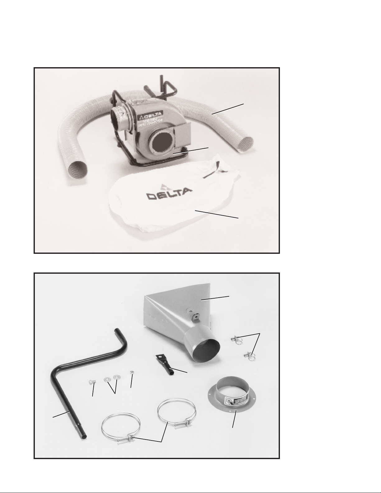
UNPACKING
Y our 50-820 Dust Collector is shipped complete in one cont ainer . Carefully remove the dust collector and all
loose p art s from the cont ainer . Figs. 2 and 3 illustrate the component s of the dust collector . W ARNING: D O N O T
CONNECT THE DUST COLLECTO R TO THE POWERSOURCE UNTIL TH E MACHINE IS COMPLETELY
ASSEMBLED AND YO U H AVE READAND UNDERSTAND THE ENTIRE OWNER S MANUAL.
1 -Dust Collector
2 -10’ long, 4 Diameter
Vacuum Hose
3 -Dust Collector Bag
Fig. 2
Fig. 3
4 -Dust Collector Hood
5 -Clamps for Tubular
Supports (2)
6-Int ake Flange
7 -Hose Clamps (2)
8 -Angled Support Tu b e
9 -5/16-18 x 5/8
Hex Head Screw
10 -5/16 Flat Washers (2)
11 -5/16-18 Hex Nut
12 -Upper Support T u be
2
1
3
4
5
6
12
7
8
9
11
10
Page 6

6
Fig. 4
ASSEMBLY
Fig. 5
Fig. 6
Fig. 7
ASSEMBLING
INTAKE FLANGE TO
DUST COLLECTO R
1. Loosen and remove four screws (A) Fig. 4, from
flange (B) of air cleaner .
2. Align holes in flange (B) Fig. 4, with four holes in
flange adapter (C) and fasten connector to dust collector
as shown in Fig. 5, with screws (A) removed in STEP 1.
NOTE: WARNING LABEL O N FLANGE ADAPTER (C)
MUST FACE TO WARD THE TOP OF DUST COLLECTOR.
ASSEMBLING SUPPORT
TUBE AND CONNECTOR TO
DUST COLLECTO R BODY
1. Assemble clamp (D) Fig. 6, onto the end of tube
(E) and insert smaller end of angled support tube (F) into
tube (E) and tighten clamp (D), as shown properly
assembled in Fig. 7.
A
C
B
A
A
C
F
D
E
Page 7

7
Fig. 8
Fig. 9
Fig. 10
Fig. 1 1
2. Align hole in upper support tube (G) Fig. 8, with
flange (H) located at the bottom connector (J) and fasten
support tube to flange with screw (K), flat washers (L),
and hex nut (M). NOTE: Flat washers will be positioned
on each side of flange.
3. Place the remaining small clamp (D) Fig. 9, onto the
split end of angle support tube (F). Insert upper support
tube assembly (G) with connector (J) att ached, and tighten
clamp (D) as shown assembled in Fig. 9.
ASSEMBLING
VACUUM HOSE TO
DUST COLLECTO R
1. Place hose clamp (A) Fig. 10, onto one end of 4
diameter vacuum hose (B) and slide hose around con nector (C) as shown in Fig. 11. Tighten hose clamp (A).
G
H
K
L
L
M
J
D
G
F
J
A
B
C
A
Page 8

8
Fig. 12
Fig. 13
Fig. 14
Fig. 15
2. Place the remaining hose clamp (A) Fig. 12, around
the other end of vacuum hose (B) and slide hose (B) onto
connector (C) and tighten hose clamp (A). NOTE: If
desired, connector (C) can be rot ated in the vertical posi tion, as shown in Fig. 13.
ASSEMBLING DUST BAG
TO DUST COLLECTO R
Loosely thread end of dust bag strap (A) through clamp
(B) as shown in Fig. 14. Place open end of dust bag (C)
Fig. 15, over outlet flange (D) and firmly pull strap (A) to
fasten dust collection bag to outlet flange.
C
A
B
C
A
B
C
A
D
Page 9

9
CONNECTING MACHINE TO POWER SOURCE
POWER CONNECTIONS
A s e p arate electrical circuit should be used for your tools. This circuit should not be less than #12 A W G a n d
should be protected with a 20 amp, time lag fuse. Have a certified electrician rep air or replace damaged or
worn cord immediately. Before connecting the motor to the power line, make cert ain the switch is in the OFF
position and be sure that the electric current is of the same characteristics as st amped on the motor nameplate. All line connections should make good cont act. Running on low voltage will damage the motor.
W ARNING: D O N O T EXPOSE THE DUST COLLECTO R TO RAIN O R OPERATETHE MACHINE IN
DAMPLOCATIONS.
M O TO R SPECIFICATIONS
The motor of the Model 50-820 Dust Collector is shipped wired for 120 Volt s. Before connecting the dust
collector to the power source, make cert ain the switch is in the OFF position.
GROUNDING INSTRUCTIONS
W ARNING: THIS TO O L MUST BE GROUNDEDWHILE IN US E TO PROTECT THE OPERATO R FROM
ELECTRIC SHOCK.
This dust collector must be grounded. If it should malfunction or break down, grounding provides a p ath of
least resist ance for electric current to reduce the risk of electric shock. This dust collector is equipped with a
cord having an equipment-grounding conductor and grounding plug. The plug must be inserted into an
appropriate outlet that is properly inst alled and grounded in accordance with all local codes and ordinances.
W ARNING: Improper connection of the equipment-grounding conductor can result in a risk of
electric shock. Check with a qualified electrician or service person if you are in doubt as to whether the out let is properly grounded. Do not modify the plug provided with the dust collector . If it will not fit the outlet, have
a proper outlet inst alled by a qualified electrician.
Fig. 16
Fig. 17
GROUNDED OUTLET BOX
CURRENT
CARRYING
PRONGS
GROUNDING BLADE
IS LONGEST O F THE 3 BLADES
GROUNDED OUTLET BOX
GROUNDING MEANS
ADAPTER
This dust collector is for use on a normal 120-volt circuit
and has a grounded plug that looks like the plug illustrat ed in Fig. 16.
If a properly grounded outlet is not available, a temporary
adapter, shown in Fig. 17, may be used for connecting
the 3-prong grounding type plug to a 2-prong recept acle.
The temporary adapter should be used only until a
properly grounded outlet can be inst alled by a qualified
electrician. The green colored rigid ear, lug, or the like
extending from the adapter must be connected to a
permanent ground such as a properly grounded outlet
box cover. Whenever the adapter is used, it must be held
in place with a met al screw.
NOTE: In Canada, the use of a temporary adapter is
not permitted by the Canadian Electric Code .
Page 10

10
EXTENSION CORDS
Use proper extension cords. Make sure your extension
cord is in good condition and is a 3-wire extension cord
which has a 3-prong grounding type plug and a 3-hole
recept acle which will accept the tool s plug. When using
an extension cord, be sure to use one heavy enough to
carry the current of the dust collector . An undersized cord
will cause a drop in line volt age resulting in loss of power
and overheating. Fig. 18, shows the correct size to use
depending on cord length. If in doubt, use the next heavier
gage. The smaller the gage number, the heavier the cord.
TO TAL LENGTH OF
CORDIN FEET
0-25
26 - 50
51 - 100
101 - 150
GAGEOF EXTENSION
CORDTO USE
16 A W G
16 A W G
14 A W G
12 A W G
Fig. 18
OPERATING CONTROLS & ADJUSTMENTS
Fig. 19
Fig. 20
Fig. 21
W ARNING: BE FORE OPERATING T H E MACHINE,
FOR OPERATO R SAFETY, MAKE CERTAIN THE DUST
INTAKE PORTIS COVEREDWITH THE VACUUM HOSE.
TH E R O TATING FA N INSIDE T H E BLOWER HOUSING IS ACCESSIBLE THROUGH THE DUST INTAKE
PORT A ND IS HAZARDOUS. ALW AYS WEARPROPER
APPAREL.D O NOT WEAR JEWELRY,AN D KEEP
FINGERS A N D ALL FOREIGN OBJECTS OU T OF
THE DUST INTAKE PORT.ALW AYS FOLLOW THE
SAFETY RULES DESCRIBED O N PAGES3 A N D 4 OF
THIS MANUAL.
STARTING A N D STOPPING
DUST COLLECTO R
The ON/OFF power switch (A) Fig. 19, is located on the
side of the motor . To turn the machine ON , move the
switch toggle (B) upward. To turn the switch OFF , move
the switch toggle (B) downward.
LOCKING SWITCH IN
T H E OFF POSITION
W e suggest that when the dust collector is not in use, the
switch be locked in the OFF position. This can be done
by grasping the switch toggle (B) Fig. 20, and pulling it
out of the switch (A) as shown. With the switch toggle
removed, the switch will not operate. However, should
the switch toggle be removed while the machine is
running, the switch can be turned OFF once, but
cannot be rest arted without inserting switch toggle (B).
SAFETY G ATES
1. The dust collector is equipped with two safety gates
(A) Fig. 21. IMPORTANT:When the dust collector is in
use, the safety gates (A) Fig. 21, should always be in the
open position, to allow dust and wood chip s to flow freely
through the vacuum hose (B) and into the dust collection
bag (C).
2. IMPORTA N T:When the dust collector is not in use,
the safety gates (A) Fig. 21, should always be pushed
inward into the closed position over the inlet and outlet
housings (as shown) to avoid anyone coming in cont act
with the fan blade or sharp edges and promote operator
safety .
A
B
A
B
B
A
A
C
Page 11

11
OPERATIONS
Fig. 22
1. This versatile dust collector is light, comp act and can
easily be transported to a variety of locations for use
in and out of the workshop. It s sturdy tubular frame (A)
Fig. 22, featuring four rubber feet, three of which are
shown at (B), allows the dust collector to sit securely on the
floor or supporting shelf without creeping or walking
across the supporting surface during operation.
A
B
B
2. Fig. 23, illustrates the dust collector positioned on the floor and at the rear of a wood
lathe to ef fectively clear the wood chip s away from the work area. Note how the support
tube (A) keeps the vacuum hose and collector hood (B) in position behind the work area,
without hindering the operator.
Fig. 23
B
A
Page 12

12
Fig. 24
Fig. 25
3. Fig. 24 illustrates the dust collector
positioned on a lower shelf and used to
collect dust in a small router applica tion. In this p articular application, the
angular support tube is not being used
to support the dust collector hood and
vacuum hose (B). However, the dust
collector hood is shown clamped at
(C) to the t able top for ef fective dust
collection.
4. The vacuum hose (B) Fig. 25, can
be fitted with a variety of connectors to
accommodate any type of woodworking machine. Fig. 25, illustrates the
dust collector positioned behind a t able
saw and att ached to the dust chute of
the saw through a specially designed
dust connector hood (D) which accept s
a 4 diameter hose.
C
B
B
D
Page 13

13
Fig. 26
Fig. 27
5. Fig. 26 illustrates the dust collector
att ached to a portable bench top planer
through an accessory dust connector
hood.
6. Cleaning out the truck bed is another application for the dust collector ,
as shown in Fig. 27; however, it should
not be us e d t o p ick u p m e t allic object s.
Page 14

14
TRANSPORTATION A N D STORAGE
Fig. 29
Fig. 30
Fig. 28
1. The dust collector features a convenient carrying
handle with rubber grip (A) Figs. 28 and 29, which allows
the unit to be carried easily from one job area to another .
IMPORTANT:THE DUST COLLECTO R WEIGHS
APPROXIMATELY 39 LBS. CARE SHOULD BE TAKEN
WHENLIFTING A N D TRANSPORTING THE MACHINE.
2. In addition to the carrying handle, the machine
features a welded mounting bracket (B) Fig. 28, with hole
for mounting the dust collector to a wall or wooden sup port (when not in use) as shown in Fig. 30. Two rubber
feet (C) Fig. 28, on the tubular frame help s support the
unit for storage and prevent s damage to wall or support ing surface. IMPORTANT:ALW AYS use safety gates to
cover dust port s when the dust collector is not in use or
mounted to a supporting surface for storage.
MAINTENANCE
NOTE: Before any maintenance or service is performed, be sure the dust collector is disconnected from the power source to prevent accident al st arting and the safety gates closed. All main tenance other than the items recommended in this manual should be performed by an authorized
Delt a Service Center.
1. IMPORTA N T:Always disconnect the machine from the power source before performing any
maintenance procedures.
2. The condition of the dust bag should be checked periodically for damage and emptied on a
regular basis. Do not transport the machine with a full dust bag.
3. Clean and apply a dry silicone lubricant monthly to the impeller to remove any dirt or build-up
of pitch, gum and wood shavings.
A
C
B
 Loading...