

Page 1
INSTRUCTION MANUAL
MACHINERY
DATED 6-22-00 PART NO. 1345771
Copyright © 2000 Delta Machinery
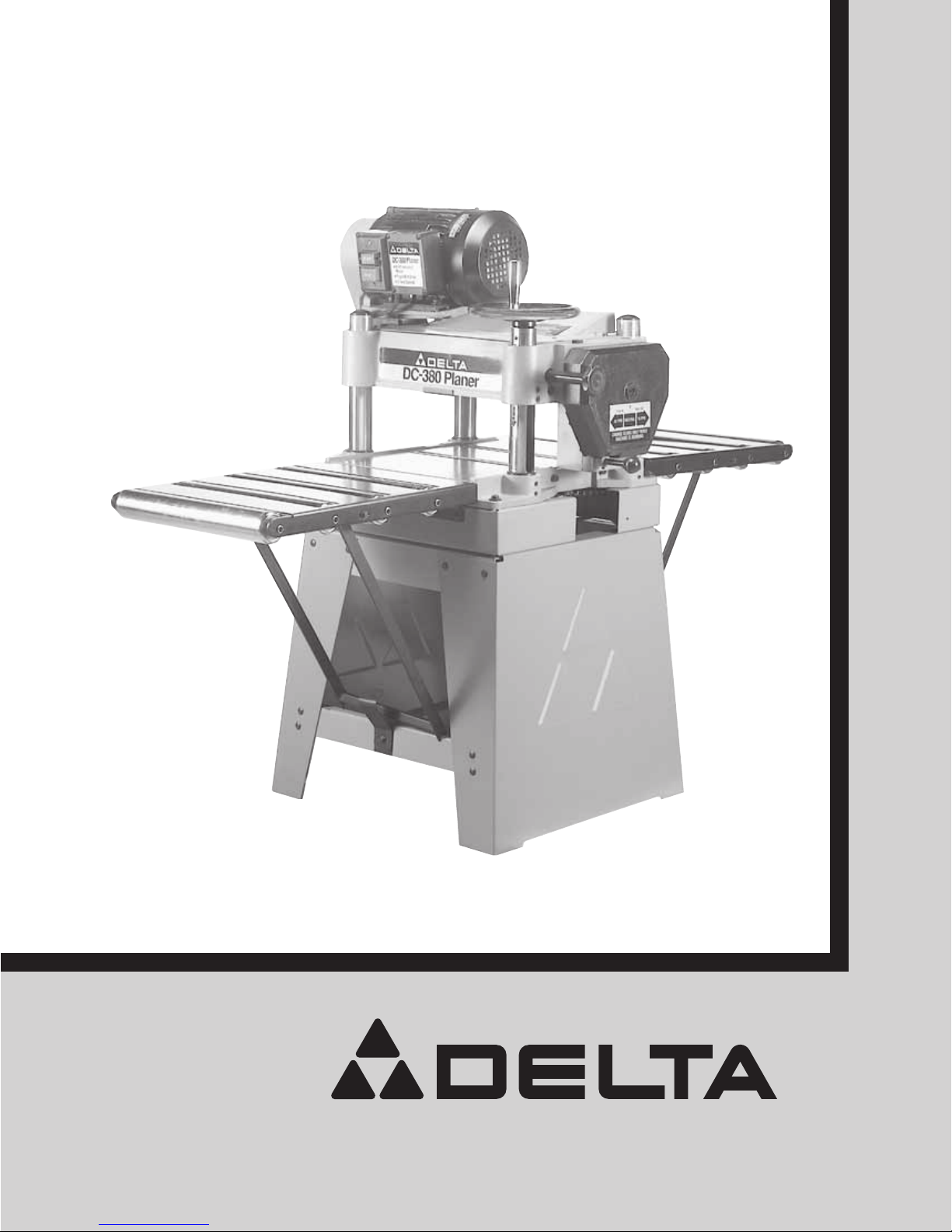
50-785 Accessory Planer Stand
and Roller Extension Tables
Planer Stand shown with
Delta Model DC-380
15
″ Planer
Page 2
2
INTRODUCTION
This manual illustrates the stand with roller extension tables assembled to a Delta DC-380 15″ Planer. The accessory
heavy-duty steel planer stand not only gives a stable support surface for the 15″ planer, but is equipped with two roller
extension tables that provide added work support and prevent sniping of the wood when planing longer workpieces. Each
table features four (4) large 2-1/4″ diameter rollers which will allow smoother, easier infeed and outfeed operations.
UNPACKING AND CLEANING
Your 15″ planer stand with roller extension tables is shipped in one container. Carefully remove the protective coating
from the machined surfaces of the extension tables. This coating may be removed with a soft cloth moistened with
kerosene. DO NOT USE ACETONE, GASOLINE OR LACQUER THINNER FOR THIS PURPOSE. Figure 2, illustrates
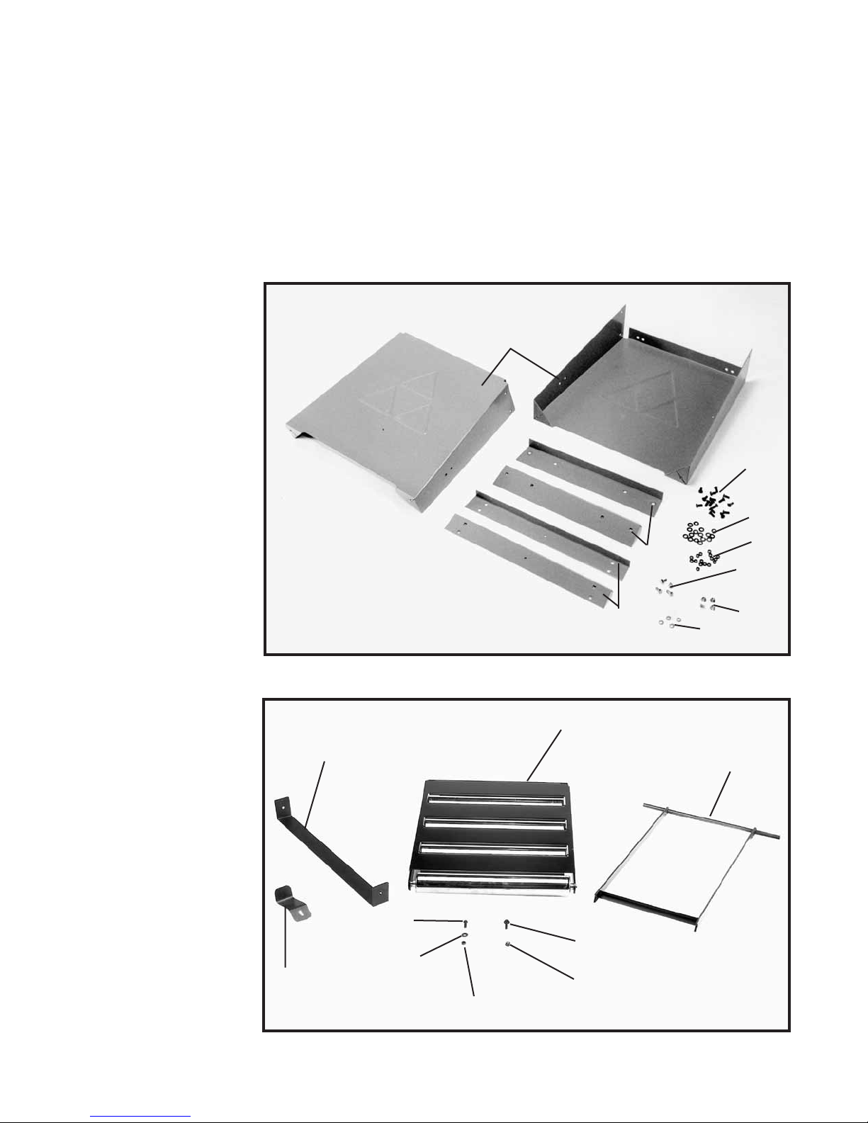
the components of the stand. Figure 3 illustrates the components of the roller extension tables.
Fig. 2
Fig. 3
1. Side Supports (2)
2. Upper Stand Support
Brackets (2)
3. Lower Stand Support
Brackets (2)
4. 5/16-18 x 3/4
″ Carriage
Head Screws (16)
5. M8 Flat Washers (16)
6. 5/16-18 Hex Nuts (16)
7. M8 x 30MM Hex Head
Screws (4)
8. M8 Flange Nuts (4)
9. M8.1 Lockwashers (4)
10. Stand Supports (2)
11. Roller Extension Tables (2)
12. 1/4-20 x 3/4″ Hex Head
Screws (6)
13. 1/4″ Flat Washers (8)
14. 1/4-20 Hex Nuts (2)
15. M6 x 20 Hex Flange
Screws (6)
16. M6 Flange Nuts (6)
17. Clips (2)
18. Leg Support
1
2
3
7
8
9
6
5
4
11
10
17
15
16
12
14
13
18
Page 3

3
Fig. 4
Fig. 6
Fig. 5
ASSEMBLING PLANER TO STAND
1. Carefully lift the planer (E) Fig. 5, onto the stand (B) as
shown. CAUTION: EXTREME CARE SHOULD BE TAKEN
WHEN LIFTING THE PLANER ONTO THE STAND AS
THE CUTTERHEAD KNIVES ARE EXTREMELY SHARP
AND THE PLANER IS VERY HEAVY. IF IT IS NOT DONE
MECHANICALLY, A MINIMUM OF FOUR PEOPLE ARE
REQUIRED TO MANUALLY LIFT THE MACHINE.
2. Align the four holes in the bottom of the planer (E)
Fig. 5, with the mounting holes in the top of stand (B), and
mount the planer to the stand with four M8 x 30MM hex
head screws (F) Fig. 5, lockwashers and flange nuts.
NOTE: Screws (F) Fig. 6, one of which is shown, are
started upward from the inside of stand (B). Later planer
models may not need flange nuts.
3. Once the planer is assembled to the stand, push
down on top of the planer so the legs of the stand adjust
to the floor surface. Tighten all stand mounting
hardware.
ASSEMBLING STAND
1. Assemble the two longer support brackets (A) Fig. 4,
one of which is shown, to the inside of end panels (B) with
eight 5/16-18 x 3/4″ carriage head screws (C), flat
washers, and 5/16-18 hex nuts. DO NOT COMPLETELY
TIGHTEN HARDWARE AT THIS TIME.
2. Assemble the two shorter support brackets (D) Fig. 4,
to the inside top of end panels (B) with the remaining
eight 5/16-18 x 3/4″ carriage head screws (C), flat washers
and 5/16-18 hex nuts. DO NOT COMPLETELY TIGHTEN
HARDWARE AT THIS TIME. NOTE: Make certain the top
lip of support brackets (D) are positioned under the top
lips of end panels (B) as shown in Fig. 4.
B
D
B
A
C
E
B
E
B
F
F
Page 4

4
Fig. 7
Fig. 8
Fig. 9
Fig. 10
ASSEMBLING SUPPORT
BRACKETS TO ROLLER
EXTENSION TABLES
1. Place extension table (A) Fig. 7, on a firm supporting
surface. Align ends of support assembly (B) Fig. 7, with
slotted holes (C) at both sides of extension table (A), and
fasten support bracket assembly to extension table with
two 1/4-20 x 3/4″ hex head screws and flat washers (D).
IMPORTANT: In the position shown in Fig. 7, make
certain the longer side of notches (E) will be closest to
hinge (F) of support table.
2. Assemble the remaining support bracket to other
extension table in the same manner.
ASSEMBLING ROLLER
EXTENSION TABLES TO
PLANER AND STAND
1. Assemble bracket clips (A) and leg support (F) Fig. 8,
to the front and rear lower stand brackets (B), one of
which is shown assembled, with two 1/4-20 x 3/4″ hex
head screws (C), four flat washers (D) and two 1/4-20 hex
nuts (E). Adjustment to height of clip can be made later.
2. Align the three holes in the hinge of extension table
(G) Fig. 9, with three holes in the front of the planer base
(H) and loosely fasten the extension table to the planer as
shown with three M6 x 20MM hex flange screws (K) and
flange nuts. NOTE: Only finger tighten the three screws at
this time as height adjustment to the table will be
necessary as explained later in STEP 4. Later planer
models may not need flange nuts.
3. Place the notches at the bottom of extension table
support (B) Fig. 10, so the longer edge of the support
rests on the ledge of bottom support bracket (L) as
shown. Adjust bracket clip (A) so it contacts the horizontal
support bar (M). Tighten screw (N) after adjustment is
made.
NOTE: Clip (A) acts as a safety device so the
extension table will not fall accidentally during operation
of the planer. Assemble the remaining roller extension
table to the rear of the planer in the same manner.
B
E
F
C
D D
A
B
A
C
E
D
G
K
K
H
L
B
M
N
A
F
Page 5

5
Fig. 12Fig. 11
Fig. 13
Fig. 14
P
A
G
B
G
4. IMPORTANT: Make certain the rollers on the
extension tables are level with the table surface of the
planer. This will provide maximum work support and
prevent sniping of the wood being planed.
5. Place a straight edge (P) Fig. 11, on the table surface
and extending out of the entire surface of the table
extension rollers as shown. Align the two surfaces and
carefully tighten three screws (K) Fig. 9, that are holding
the extension table to the base of the planer. Readjust
bracket clip (A) if necessary.
6. When not in use, the roller extension tables (G) Fig. 12,
one of which is shown, can be lowered in front and back
of the planer to prevent accidental movement, which
could result in misalignment of the rollers. To lower the
tables, raise the end of extension table (G) Fig. 13,
slightly to relieve pressure on the table support (B) and
move the table support inward away from clip (A), while
lowering extension table (G).
7. Fig. 14, illustrates the stand with roller extension
tables assembled to a Delta 15″ DC-380 Planer.
A
Page 6

6
Delta will repair or replace, at its expense and at its option, any Delta machine, machine part, or
machine accessory which in normal use has proven to be defective in workmanship or material,
provided that the customer returns the product prepaid to a Delta factory service center or authorized service station with proof of purchase of the product within two years and provides Delta with
reasonable opportunity to verify the alleged defect by inspection. Delta may require that electric
motors be returned prepaid to a motor manufacturer’s authorized station for inspection and repair
or replacement. Delta will not be responsible for any asserted defect which has resulted from
normal wear, misuse, abuse or repair or alteration made or specifically authorized by anyone other
than an authorized Delta Service facility or representative. Under no circumstances will Delta be
liable for incidental or consequential damages resulting from defective products. This warranty is
Delta’s sole warranty and sets forth the customer’s exclusive remedy, with respect to defective
products; all other warranties, express or implied, whether of merchantability, fitness for purpose,
or otherwise, are expressly disclaimed by Delta.
MACHINERY
Delta Building Trades and Home Shop Machinery
Two Year Limited Warranty
MACHINERY
PARTS, SERVICE OR WARRANTY ASSISTANCE
All Delta Machines and accessories are manufactured to high quality standards and are serviced by a
network of Porter-Cable/Delta Factory Service Centers and Delta Authorized Service Stations. To obtain
additional information regarding your Delta quality product or to obtain parts, service, warranty assistance, or
the location of the nearest service outlet, please call 1-888-848-5175.
Printed in U.S.A.
 Loading...