

Page 1
2004-7 Delta Elite Manual
Warranty Registration Card must be filled out by the customer and mailed within thirty (30) days of installation in order to gain warranty coverage.
When receiving Triangle Tube units, any claims for damage or shortage in shipment must be filed immediately against the transportation company by the consignee.
Leave all documentation received with appliance with owner for future reference.
WARNING
* I N S
* I N S TTAALLLLAATT
I O N
I O N AA
N D M
N D M AA
I N
I N TT
E N
E N AA
N C E *
N C E *
M
M AA
N U
N U AALL
- Input from 100,000 to 199,000 Btu/hr -
NOTICE
F-25/30/35/40 & 45
Combination Heaters
If the information in this manual is not followed exactly, a fire or explosion may
result causing property damage, personal injury or death.
For Your Safety
• Do not store or use gasoline or other flammable vapors and liquids in the vicinity of this or any other
appliance.
• WHAT TO DO IF YOU SMELL GAS
- Do not try to light any appliance
- Do not touch any electrical switch; do not use any phone in your building.
- Immediately call your gas supplier from a neighbor’s phone. Follow the gas supplier’s instructions.
- If you cannot reach your gas supplier, call the fire department.
Installation and service must be performed by a qualified installer, service agency or the gas supplier
The
CONFORMS TO
ANSI Z 21-10-3/UL 732
CERTIFIED TO
90870
CSA B 140.12
CGA/CAN 1-4.3-M85
Page 2
Table of Contents
i
PRODUCT AND SAFETY INFORMATION
Definitions . . . . . . . . . . . . . . . . . . . . . . . . . . . . . . . . . . . . . . . . . . . . . . . . 1
Product Warnings . . . . . . . . . . . . . . . . . . . . . . . . . . . . . . . . . . . . . . . . . . . 2-3
Operating Restrictions . . . . . . . . . . . . . . . . . . . . . . . . . . . . . . . . . . . . . . . 4
Code Restrictions . . . . . . . . . . . . . . . . . . . . . . . . . . . . . . . . . . . . . . . . . . . 4
SECTION I - PRE-INSTALLATION ITEMS
Code Compliance . . . . . . . . . . . . . . . . . . . . . . . . . . . . . . . . . . . . . . . . . . . 5
Determining Product Location . . . . . . . . . . . . . . . . . . . . . . . . . . . . . . . . . 5
Boiler Replacement . . . . . . . . . . . . . . . . . . . . . . . . . . . . . . . . . . . . . . . . . 5
Recommended Clearances . . . . . . . . . . . . . . . . . . . . . . . . . . . . . . . . . . . . 5-6
Flooring and Foundation. . . . . . . . . . . . . . . . . . . . . . . . . . . . . . . . . . . . . . 6
Residential Garage Installations . . . . . . . . . . . . . . . . . . . . . . . . . . . . . . . . 6
SECTION II - COMBUSTION AIR AND VENTING
Providing Air for Combustion and Ventilation . . . . . . . . . . . . . . . . . . . . . 7-8
Removal of an Existing Boiler from a Common Vent . . . . . . . . . . . . . . . . 8
SECTION III - UNIT PREPARATION
Handling Instructions . . . . . . . . . . . . . . . . . . . . . . . . . . . . . . . . . . . . . . . . 9
Hydrostatic Pressure Test
Hydrostatic Test Preparation . . . . . . . . . . . . . . . . . . . . . . . . . . . . . 9
Hydrostatic Test Procedures . . . . . . . . . . . . . . . . . . . . . . . . . . . . . 9-10
Completion of Hydrostatic Test and Draining . . . . . . . . . . . . . . . . 10
SECTION IV - DOMESTIC PIPING
General Piping Requirements . . . . . . . . . . . . . . . . . . . . . . . . . . . . . . . . . . 11
Domestic Supply Pressure . . . . . . . . . . . . . . . . . . . . . . . . . . . . . . . . . . . . 11
Thermal Expansion. . . . . . . . . . . . . . . . . . . . . . . . . . . . . . . . . . . . . . . . . . 11
Water Hammer . . . . . . . . . . . . . . . . . . . . . . . . . . . . . . . . . . . . . . . . . . . . . 11
Temperature / Pressure Relief Valve . . . . . . . . . . . . . . . . . . . . . . . . . . . . . 11-12
Thermostatic Mixing Valve. . . . . . . . . . . . . . . . . . . . . . . . . . . . . . . . . . . . 12
Page 3
Table of Contents
ii
U-Tube Assembly . . . . . . . . . . . . . . . . . . . . . . . . . . . . . . . . . . . . . . . . . . . 12-13
Domestic Drain Valve. . . . . . . . . . . . . . . . . . . . . . . . . . . . . . . . . . . . . . . . 13
Multiple Units Installation . . . . . . . . . . . . . . . . . . . . . . . . . . . . . . . . . . . . 13
Storage Tank Application . . . . . . . . . . . . . . . . . . . . . . . . . . . . . . . . . . . . . 13
TR/Smart Series Application. . . . . . . . . . . . . . . . . . . . . . . . . . . . . . . . . . . 14
Domestic Piping Diagrams . . . . . . . . . . . . . . . . . . . . . . . . . . . . . . . . . . . . 14-16
SECTION V - PRIMARY PIPING
General Piping Requirements
Low Water Cut-off Device . . . . . . . . . . . . . . . . . . . . . . . . . . . . . . 17
Backflow Preventer. . . . . . . . . . . . . . . . . . . . . . . . . . . . . . . . . . . . 17
Primary System Piping Applications. . . . . . . . . . . . . . . . . . . . . . . . . . . . . 17
Expansion Tank and Makeup Water
Diaphragm (Bladder) Expansion Tank . . . . . . . . . . . . . . . . . . . . . . 17
Closed-Type (Standard) Expansion Tank . . . . . . . . . . . . . . . . . . . . 17
Circulator . . . . . . . . . . . . . . . . . . . . . . . . . . . . . . . . . . . . . . . . . . . . . . . . . 18
Closet (Zero Clearance) Applications . . . . . . . . . . . . . . . . . . . . . . . . . . . . 18
Sizing Primary Piping. . . . . . . . . . . . . . . . . . . . . . . . . . . . . . . . . . . . . . . . 18
System Piping - Zone Circulators . . . . . . . . . . . . . . . . . . . . . . . . . . . . . . . 18
System Piping - Zone Valves . . . . . . . . . . . . . . . . . . . . . . . . . . . . . . . . . . 18
System Piping - Radiant Heating with Mixing Valves . . . . . . . . . . . . . . . . 18-19
System Piping - Multiple Units Installation. . . . . . . . . . . . . . . . . . . . . . . . 19
Primary Piping Diagrams . . . . . . . . . . . . . . . . . . . . . . . . . . . . . . . . . . . . . 20-23
SECTION VI - VENTING
General Requirements. . . . . . . . . . . . . . . . . . . . . . . . . . . . . . . . . . . . . . . . 24
Oil Vent Piping . . . . . . . . . . . . . . . . . . . . . . . . . . . . . . . . . . . . . . . . . . . . . 24-25
Oil Vent -Direct Vent Applications . . . . . . . . . . . . . . . . . . . . . . . . . . . . . . 25
Gas Venting - General Requirements . . . . . . . . . . . . . . . . . . . . . . . . . . . . 26
Masonry and Metal Chimneys . . . . . . . . . . . . . . . . . . . . . . . . . . . . . . . . . 26
Type B Vent Systems . . . . . . . . . . . . . . . . . . . . . . . . . . . . . . . . . . . . . . . . 26
Vent Connectors . . . . . . . . . . . . . . . . . . . . . . . . . . . . . . . . . . . . . . . . . . . . 27
Common Vent System . . . . . . . . . . . . . . . . . . . . . . . . . . . . . . . . . . . . . . . 27
SECTION VII - FUEL PIPING
Gas Supply Piping Connection . . . . . . . . . . . . . . . . . . . . . . . . . . . . . . . . . 28
Pipe sizing -Natural Gas . . . . . . . . . . . . . . . . . . . . . . . . . . . . . . . . . . . . . . 29
Natural Gas Supply Pressure Requirements . . . . . . . . . . . . . . . . . . . . . . . 29
Page 4
iii
Table of Contents
Pipe Sizing - Propane Gas . . . . . . . . . . . . . . . . . . . . . . . . . . . . . . . . . . . . 30
Propane Gas Supply Pressure Requirements . . . . . . . . . . . . . . . . . . . . . . . 30
General Oil Piping Guidelines . . . . . . . . . . . . . . . . . . . . . . . . . . . . . . . . . 30
SECTION VIII - INTERNAL WIRING
General Requirements. . . . . . . . . . . . . . . . . . . . . . . . . . . . . . . . . . . . . . . . 31
Internal Control Wiring Diagrams. . . . . . . . . . . . . . . . . . . . . . . . . . . . . . . 31-32
SECTION IX - EXTERNAL WIRING
Installation Compliance . . . . . . . . . . . . . . . . . . . . . . . . . . . . . . . . . . . . . . 33
Line Voltage Connections . . . . . . . . . . . . . . . . . . . . . . . . . . . . . . . . . . . . . 33
Thermostat Wiring . . . . . . . . . . . . . . . . . . . . . . . . . . . . . . . . . . . . . . . . . . 33
Outdoor Temperature Limit . . . . . . . . . . . . . . . . . . . . . . . . . . . . . . . . . . . 33
External Control Wiring Diagrams . . . . . . . . . . . . . . . . . . . . . . . . . . . . . . 34-36
SECTION X - START-UP PREPARATION
Check System and Domestic Water Chemistry
Water pH Level 6.0 to 8.0 . . . . . . . . . . . . . . . . . . . . . . . . . . . . . . . 37
Water Hardness Less Than 7 Grains . . . . . . . . . . . . . . . . . . . . . . . 37
Chloride Concentration Less Than 80mg/L . . . . . . . . . . . . . . . . . . 37
Chlorinated Water . . . . . . . . . . . . . . . . . . . . . . . . . . . . . . . . . . . . . 37
Flush Primary and Domestic System. . . . . . . . . . . . . . . . . . . . . . . . . . . . . 37
Check and Test Antifreeze . . . . . . . . . . . . . . . . . . . . . . . . . . . . . . . . . . . . 37
Use of Antifreeze in the Primary System . . . . . . . . . . . . . . . . . . . . . . . . . 38
Filling the Inner (Domestic) Tank and System . . . . . . . . . . . . . . . . . . . . . 38
Filling the Outer (Primary) Tank and System . . . . . . . . . . . . . . . . . . . . . . 38-39
Check Low Water Cut-off Device . . . . . . . . . . . . . . . . . . . . . . . . . . . . . . 39
Check for Gas Leaks . . . . . . . . . . . . . . . . . . . . . . . . . . . . . . . . . . . . . . . . 39
Check Thermostat Circuit . . . . . . . . . . . . . . . . . . . . . . . . . . . . . . . . . . . . . 39
SECTION XI - START-UP PROCEDURES
Final Checks Before Start-up . . . . . . . . . . . . . . . . . . . . . . . . . . . . . . . . . . 40
ELITE Start-up. . . . . . . . . . . . . . . . . . . . . . . . . . . . . . . . . . . . . . . . . . . . . 40-41
Page 5
iv
Table of Contents
SECTION XII - TEMPERATURE LIMITS
Setting Primary Thermostat Limit. . . . . . . . . . . . . . . . . . . . . . . . . . . . . . . 42
Adjustment of Secondary Thermostat Limit . . . . . . . . . . . . . . . . . . . . . . . 42
Setting the Thermostatic Mixing Valve . . . . . . . . . . . . . . . . . . . . . . . . . . . 43
SECTION XIII - CHECK-OUT PROCEDURES
Check-out Procedures . . . . . . . . . . . . . . . . . . . . . . . . . . . . . . . . . . . . . . . . 44
SECTION XIV - INSTALLATION RECORD
Installation Record . . . . . . . . . . . . . . . . . . . . . . . . . . . . . . . . . . . . . . . . . . 45
SECTION XVII - REPLACEMENT PARTS
Replacement Parts . . . . . . . . . . . . . . . . . . . . . . . . . . . . . . . . . . . . . . . . . . 46-49
PRODUCT SPECIFICATIONS
Specifications . . . . . . . . . . . . . . . . . . . . . . . . . . . . . . . . . . . . . . . . . . . . . . 50-51
Page 6
Product & Safety Information
1
Indicates the presence of a hazardous
situation which, if ignored, will result
in death, serious injury or substantial
property damage.
Indicates a potentially hazardous situation which, if ignored, can result in
death, serious injury or substantial
property damage.
Indicates a potentially hazardous situation which, if ignored, may result in
minor injury or property damage.
Indicates special instructions on installation, operation or maintenance,
which are important to equipment but
not related to personal injury hazards.
Indicates recommendations made by
Triangle Tube for the installers which
will help to ensure optimum operation
and longevity of the equipment
BEST PRACTICES
NOTICE
CAUTION
WARNING
DANGER
The following terms are used throughout this manual to bring attention to the presence of
potential hazards or to important information concerning the product.
Triangle Tube reserves the right to modify the technical specifications and components of
its products without prior notice.
NOTICE
Page 7
Product & Safety Information
2
Bacteria can develop in the domestic
water system if certain minimum water
temperatures are not maintained.
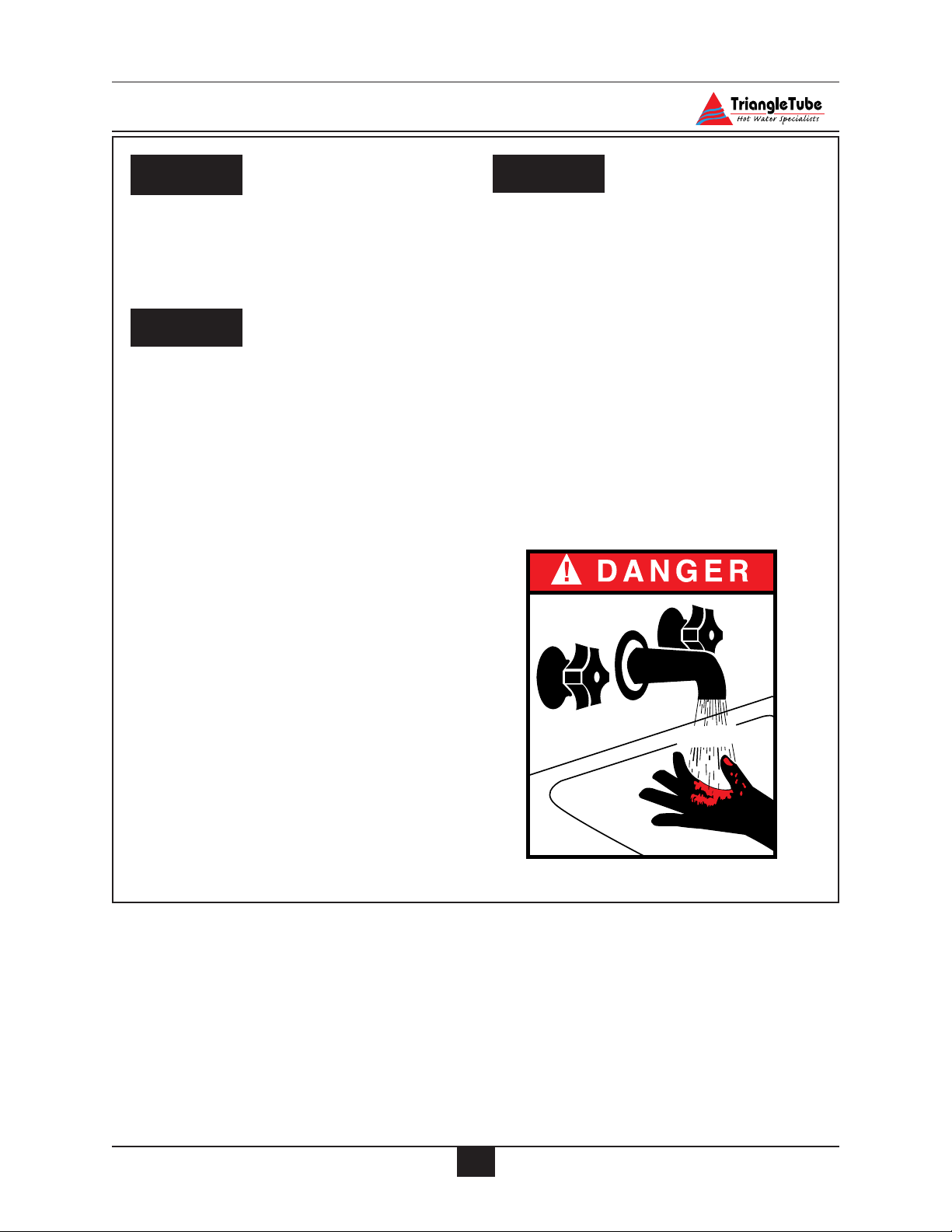
Water temperature over 125ºF can cause
severe burns instantly or death from
scalds.
• Children, disabled and elderly are at
highest risk of being scalded.
- Never leave them unattended in or
near shower, bathtub or sink.
- Never allow small children to use a
hot water faucet or draw their own
bath.
• If any one using hot water in the building
fits this description or codes require specific water temperatures at hot water
faucet, we recommend:
a) ensure the factory installed thermosta-
tic mixing valve is working properly.
b)to set the thermostatic mixing valve
for the lowest temperature which satisfies your hot water need.
.
Protection must be taken against excessive
temperature and pressure!
TO PROTECT AGAINST EXCESSIVE
TEMPERATURE AND PRESSURE
• Check if the Temperature and
Pressure (T&P) relief valve is in the
location provided. (Domestic Water)
• Check if the 30 psi relief valve supplied is in the location provided.
(Primary water)
•To avoid injury, install the relief
devices to comply with local code
requirements.
CAUTION
DANGER
WARNING
HOT
BURN
Page 8
3
Product & Safety Information
Do not use this appliance if any part
has been under water. Immediately call
a qualified service technician to inspect
the appliance and to replace any part of
the control system which has been
under water.
WHAT TO DO IF YOU SMELL GAS
- Do not try to light any appliance
- Do not touch any electrical switch; do
not use any phone in your building.
- Immediately call your gas supplier
from a neighbor’s phone. Follow the
gas supplier’s instructions.
- If you cannot reach your gas supplier, call the fire department.
Installation and service must be performed by a qualified installer, service
agency or the gas supplier.
Should overheating occur or the gas
supply fails to shut off, turn OFF the
manual gas control valve external to
the appliance.
To prevent damage to inner tank,
installer must:
• Fill inner tank prior to outer tank
during start-up.
• Relieve primary system pressure
below 15 psig prior to draining
inner tank.
CAUTION
WARNING
DANGER
DANGER
Qualified Installer:
Prior to installing this product read all
instructions included in this manual.
Perform all installation steps required in this
manual in the proper order given. Failure to
adhere to the guidelines within this manual
can result in severe personal injury, death or
substantial property damage.
Homeowner:
-This product should be maintained / serviced and inspected annually by a qualified service technician.
- This manual is intended for use by a
qualified Installer/Service Technician.
Please reference the unit’s model number and the serial number from the rating label when inquiring about service or
troubleshooting.
Triangle Tube accepts no liability for any
damage resulting from incorrect installation or from the use of components or
fittings not specified by Triangle Tube.
NOTICE
NOTICEWARNING
Page 9

4
Product & Safety Information
OPERATING RESTRICTIONS
• Maximum working pressure for inner
(domestic water) tank is 150 psig.
• Maximum working pressure for outer
(primary water) tank is 45 psig.
• Inner tank has factory installed
Temperature & Pressure Relief Valve
with an AGA rating of 100,000 Btu/hr
for PG-25 and 200,000 Btu/hr for PG30/35/40/45.
• Outer tank has a factory installed 30
psig relief valve rated at 535,000 Btu/hr
• Electrical rating:120 V, 60 Hz, less
than 12 amperes
• pH & chloride limits for the ELITE are:
- Chloride, less than 80 mg/l.
- pH, 6.0 - 8.0.
Any water conditioning system must be
installed and maintained in accordance
with manufacturer’s specifications.
• 180º Maximum operating temperature primary side.
• 120º Maximum outlet/mixed temperature - domestic side.
CODE RESTRICTIONS
Single wall heat exchanger in the ELITE
complies with National Standard Plumbing
Code, provided that:
- Outer tank water (including additives)
is practically non-toxic, having toxicity
rating or Class of 1, as listed in Clinical
Toxicology of Commercial Products,
- Outer tank pressure is limited to maximum 30 psig by approved relief valve.
Single wall heat exchangers are permitted under
the Uniform Plumbing code - Paragraph L3.2. if
they satisfy all of the following requirements.
1. The heat transfer medium is potable
water or contains only substances which
are recognized as safe by the U.S. Food
and Drug Administration.
2. The pressure of the heat transfer medium
is maintained less than the normal minimum operating pressure of the potable
water system
3. The equipment is permanently labeled
to indicate that only additives recognized as safe by the FDA shall be used in
the heat transfer medium.
Or, per Uniform Plumbing Code paragraph L3.3
as follows:
Other heat exchanger designs may be permitted
where approved by the Administrative Authority.
NOTICE
Page 10

Pre-Installation Items
5
SECTION I - Pre-Installation Items
Code Compliance
This product must be installed in accordance to the following:
• All applicable local, state, national and
provincial codes, ordinances, regulations and laws.
• The National Fuel Gas Code NFPA54/
ANSI Z332.1 - Latest edition.
• Installation of Oil Burning Equipment
NFPA 31 - Latest Edition
• National Electric Code ANSI/NFPA 70.
• For installations in Canada -“Installation
Code for Gas Burning Equipment”
CGA/B149.
• For installations in Canada - Installation
code for Oil Burning Equipment CSA/B139.
Determining Product Location
Before locating the ELITE check for convenient locations to:
- Domestic water supply piping
- Heating system piping
-Venting
- Gas or oil supply piping
- Electrical service
Ensure the area chosen for the installation of
the ELITE is free of any combustible materials,
gasoline and other flammable liquids.
Failure to remove or maintain the area
free of combustible materials, gasoline
and other flammable liquids or vapors
can result in severe personal injury,
death or substantial property damage.
Ensure the ELITE and its controls are protected from dripping or spraying water during normal operation or service.
The ELITE should be installed in a location so
that any water leaking from the tank or piping
connections or relief valves will not cause
damage to the area surrounding the unit or any
lower floors in the structure.
- When such a location is unavoidable a
suitable drain pan with adequate
drainage should be placed under the
unit. The drain pan must not restrict the
flow of combustion air to the unit.
Boiler Replacement
If the ELITE is replacing an existing boiler /
hot water heater system, the following items
should be checked and corrected prior to installation:
• Primary and domestic piping leaks and
corrosion.
• Improper location and sizing of the
expansion tank on the primary heating
loop.
• Improper sizing of the thermal expansion tank (if used) on the domestic supply line.
•Vent condition and sizing.
Recommended Clearances
The ELITE is approved for zero clearance to
combustibles, excluding the vent hood and
vent piping.
Vent hood and vent piping - 6 inches from
combustible materials when using type “L”
double wall vent.
Vent Piping - 18 inches from combustible
materials when using single wall vent.
Primary and domestic hot water piping - 1 inch
from combustible material.
WARNING
Page 11

Pre-Installation Items
To provide serviceability to the unit it is
recommended that the following clearances be maintained:
Top and vent hood area - 36 inches.
Front and burner area - 24 inches.
Rear and primary piping areas - 12
inches.
When installing the ELITE in a confined
space, sufficient air must be provided for
proper combustion and venting and to
allow under normal operating condition,
proper air flow around the product to
maintain ambient temperatures within
safe limits to comply with the National
Fuel Gas Code NFPA 54 - latest edition.
Flooring and Foundation
The ELITE is approved for installation on
combustible floors, but never on carpeting.
Do not install the ELITE on carpeting
even with a metal or wood foundation
base. Fire can result causing severe personal injury, death or substantial property damage.
Installer should provide a solid brick or concrete foundation pad, at least 2 inches above
the floor level if:
- There is a potential for the floor to
become flooded. The height of the
foundation should be such to sufficiently elevate the unit.
- The floor is dirt, sand, gravel or other
loose material.
- The flooring is severely uneven or
sloped.
The minimum foundation size required is 24
inches x 23 inches.
Residential Garage Installations
When installing the ELITE in a residential
garage the following special precautions per
NFPA 54/ANSI Z223.1 must be taken:
- Mount the unit with a minimum 18
inches above the floor level of the
garage. Ensure the burner and ignition
devices / controls are no less than 18
inches above the floor level.
- Locate or protect the unit in a matter
so it cannot be damaged by a moving
vehicle.
WARNING
WARNING
BEST PRACTICES
6
Page 12

Combustion Air and Venting
7
SECTION II - Providing Air for
Combustion and Ventilation
The installer must provide adequate
combustion and ventilation to the area in
which the ELITE is installed. Providing
adequate air ensures proper combustion
and reduces the potential risk of severe
personal injury or death from carbon
monoxide emissions if a flue gas leakage
occurred.
The installer should not install an
exhaust fan in the room with the ELITE.
The exhaust fan could affect the combustion of the burner or cause potential flue
gas leakage resulting in severe personal
injury or death.
The installer should take the condition
and age of the building when determining air for ventilation. Older building
(buildings with single pane windows and
minimal weather-stripping around doors
and windows) tend to have adequate natural infiltration and ventilation without
providing dedicated air openings.
Newer buildings (buildings with double
pane windows and weather-stripped
doors and windows) are unlikely to have
natural infiltration and ventilation, thus
must be provided with dedicated air
openings.
The installer must follow the requirements of
state, provincial or local codes when sizing and
locating adequate air openings for combustion
and ventilation.
In absence of the codes the installer may opt to
use the following guidelines when the ELITE
is installed in a confined room as defined by
NFPA 31 as a room with less than 7200 cubic
feet per 1 GPH of input of all appliances located in the area (7200 cubic feet is define as a
room with 8 foot ceiling and 33.5 ft x 33.5 ft in
dimension):
Two Permanent Openings - One opening
must commence within 12 inches of the ceiling
and the other opening within 12 inches of the
floor. The opening must have a minimum
height or length dimension of 3 inches, the
actual dimensions are based on:
Using Inside Air - Each opening must be connected freely to the areas having adequate infiltration from the outside. Each opening should
be at least 140 sq. inches per 1 GPH of input (1
sq. inch per 1000 BTU input). This input
should include all appliances (gas and/or oil)
plus any appliances that may draw air from the
room such as clothes dryers.
Using Outside Air - Each opening should be
connected directly or by ducts to the outdoors
or to a crawl space or attic area that is freely
connected with the outdoors. The openings
should be sized as follows:
Through outside wall or vertical ducts -
The openings should be a minimum 35 sq
inches per 1 GPH input (1 sq. inch per 4000
BTU input) of all appliances (gas and/or
oil) plus any appliances that may draw air
from the room such as clothes dryers.
Through horizontal ducts - The openings
should be a minimum 70 sq. inches per 1
GPH input (1 sq. inch per 2000 BTU input)
of all appliances (gas and/or oil) plus any
appliances that may draw air from the room
such as clothes dryers.
Where ducts are used, the size of the duct
should equal the free area of the opening in
which the duct is connected to.
NOTICE
WARNING
WARNING
Page 13

8
Combustion Air and Venting
The installer should compensate for any louvers, grilles or screens when determining the
free air of the opening. The installer should
refer the louver or grille manufacturer’s
instruction for determining free area. In
absence of the manufacturer’s instructions the
installer should use the following as a guideline:
-Wood louvers will provide 20 to 25%
free area
-Metal louvers or grilles will provide 60
to 75% free air
Installers should lock louvers in the open position or provide an interlock system to prove the
louvers are in the open position prior to operation of the ELITE.
Removal of an Existing Boiler from a
Common Vent System
For installations in which the ELITE is
replacing an existing boiler / hot water
heater system, which was connected to a
common vent system with other appliances, the following steps shall be conducted with each remaining appliance
connected to the common venting system:
1. Any unused openings in the common
venting system must be sealed.
2. A visual inspection of the venting system must be conducted for proper sizing and horizontal pitch. The inspection should ensure no blockage or
restriction is within the vent system,
and there is no leakage, corrosion or
other items, which could cause an
unsafe condition.
3. To adequately test the venting system,
close all exterior doors and windows
and all doors between the area containing the remaining appliances connected
to the common vent system and other
areas of the building. Turn on any
clothes dryers and any other gas appli-
ance not connected to the common vent
system. Turn on all exhaust fans, i.e.
range hoods and bathroom exhaust
fans, preferably at maximum speed.
Close any fireplace dampers.
4. Place in operation the first appliance
being inspected that is connected to the
common vent system. The remaining
appliances should not be in operation.
Follow the appliance’s lighting instructions and adjust the thermostat to allow
the appliance to operate continuously.
5. Test for spillage at the draft hood relief
opening after 5 minutes of main burner
operation. Spillage can be detected
using the flame of a match or candle or
with smoke from a cigarette.
6. Once it has been determined that each
remaining appliance connected to the
common vent system is properly vented, return doors, windows, exhaust
fans, fireplace dampers and any operating gas appliance to their previous
condition.
Should any improper operation of the common
venting system be detected in the outlined test,
the condition should be corrected so the vent
system conforms with the National Fuel Gas
Code, NFPA 54/ ANSI Z223.1 - latest edition.
Canadian installations must conform with
B149.1 or 149.2 Installation Code.
BEST PRACTICES
Page 14

9
Unit Preparation
SECTION III - Unit Preparation
Handling Instructions
The ELITE is generally easier to handle and
maneuver once removed from the shipping carton and pallet.
To remove the shipping carton and pallet:
a. Remove the shipping straps and open
the top of the shipping carton to remove
the wood shipment insert.
b. Lift the shipping carton over the unit to
remove. If ceiling height is limited the
carton maybe cut open using care not to
damage the exterior jacket of the unit.
c. Discard all packing materials.
Hydrostatic Pressure Test
Prior to permanently connecting water,
oil/gas supply or electrical supply, perform a pressure hydrostatic test of the
outer tank to ensure all piping connections were not damaged during shipment.
Hydrostatic Test Preparation
1. Mount the circulator on the supply pipe as
shown in Fig. 7 page 20.
2. Temporarily plug the primary return connections as shown in Fig. 7 page 20 using a
1” NPT pipe plug. Use pipe dope sparingly to allow removal of the plugs upon completion of the test.
3. On the outlet flange of the circulator pipe
install a 1” NPT nipple and shut-off valve.
Use pipe dope sparingly to allow removal
of the fittings upon completion of the test.
To avoid getting water onto the unit
and/or surrounding area additional piping from the shut-off to a catch bucket or
drain may be required.
4. Connect a hose to the primary circuit drain
valve located per Fig. 28 page 50, Item 2
and connect the other end to a fresh water
supply. Ensure the hose can be used as a
drain hose upon completion of the test.
Hydrostatic Test Procedures
1. Open the shut-off valve installed on the
outlet flange of the circulator.
2. Open the fresh water supply valve and then
open slowly the primary circuit drain valve
to fill the outer tank with water.
3. When the water within the outer tank
reaches the shut-off on the primary supply,
close the primary circuit drain valve.
4. Close the shut-off valve, on the top of the
circulator.
5. Slowly reopen the primary circuit drain
valve until the test pressure on the temperature / pressure gauge reaches 10 psig
maximum. Close the primary circuit drain
valve.
To prevent damage to the inner tank the
test pressure must not exceed 10 psig.
6. Allow the test pressure to remain for 10
minutes.
Do not leave the unit unattended while
pressurized. A cold water fill could
expand and cause excessive pressure,
resulting in severe personal injury, death
or substantial property damage.
WARNING
CAUTION
NOTICE
BEST PRACTICES
Page 15

10
Unit Preparation
7. Ensure constant gauge pressure has been
maintained throughout the 10 minute test.
Check for leaks at all fitting joints. Repair
if found.
Leaks must be repaired immediately
when detected. Failure to repair leaks
can damage the unit, resulting in substantial property damage.
8. Check continuity using a voltmeter across
the terminals of the LWCO device. The
contacts on the LWCO should be closed.
See item 6 in Fig. 24 page 47 for location
of the LWCO.
Completion of Hydrostatic Test and Draining
1. Disconnect the fill hose from the fresh
water source and direct the hose to a suitable place of drainage.
2. Open the primary drain valve and completely drain the unit. To aid in draining, open the
shut-off valve on the primary supply.
3. Remove the hose from the primary drain
valve when draining is complete.
4. Remove the plugs, nipple, shut-off valve
and any other piping unless they will
remain for use in the system piping.
WARNING
Page 16
11
Domestic Piping
SECTION IV - Domestic Piping
General Piping Requirements
• All plumbing must meet or exceed all
local, state and national plumbing codes.
• Use pipe dope or tape suitable for
potable water.
• Use isolation valves to isolate system
components.
• Install unions for easy removal of the
ELITE from the system piping.
Domestic Supply Pressure
For applications in which the domestic supply pressure exceeds 70 psig it is recommended to install a pressure reducing valve
on the cold water supply.
Maintaining the cold water supply at or
below 70 psig will prevent normal thermal
expansion from repeatedly forcing the T&P
relief valve open.
Thermal Expansion
If the cold water supply contains a backflow
preventer, check valve and / or a pressure
reducing valve, the installer must install a
domestic thermal expansion tank on the cold
water supply. (See Fig. 2 page 14)
Installing a thermal expansion tank will
prevent normal thermal expansion from
repeatedly forcing the T&P relief valve
open.
When installing a thermal expansion tank
ensure the charge pressure of the tank is
equal to the cold water supply pressure at
the point of installation. Consult the thermal expansion tank manufacturer’s instructions for further information on installation
and sizing.
The Temperature / Pressure relief valve
is not intended for constant duty, such as
relief of pressure due to normal thermal
expansion.
Water Hammer
Water hammer is the effect of sudden pressure changes occurring in the domestic piping. These pressure changes are typically
the result of “fast acting” positive shut-off
valves closing. These types of valves can
be typically found on dishwashers and
clothes washers.
The effects of water hammering can cause
damage to system components and tank
welds on the unit.
Installation of hammer arresters is recommended at these types of appliances, which
incorporate “fast-acting” positive shut-off
valves. Consult the manufacturer of water
hammer arresters for recommendation on
sizing and installation requirements.
Temperature / Pressure Relief Valve
The ELITE has a factory installed
Temperature / Pressure Relief valve.
Ensure the rating of the T&P relief valve is
correctly sized as follows per AGA:
CAUTION
Model AGA Rating
F-25 100,000 Btu/hr
F-30 200,000 Btu/hr
F-35 200,000 Btu/hr
F-40 200,000 Btu/hr
F-45 200,000 Btu/hr
Page 17

Domestic Piping
12
The installer must install discharge piping
onto the T&P relief valve. The discharge
piping must be:
• Made of material serviceable for temperatures of 250ºF or greater.
• Directed so that any hot water discharge flows away from all persons.
• Directed to a suitable place of drainage.
• Installed as to allow complete draining
of the T&P relief valve and the discharge piping.
•Terminated with a plain end, not with
threads.
Failure to properly direct the discharge
piping of the T&P relief valve may result
in flooding of the area adjacent to the
unit and or lower floors in the structure
causing substantial property damage.
The installer must not install the T&P
relief valve discharge piping in a manner
that is:
• Excessively long: Using more than 2
elbows and/or 15 feet of discharge piping can reduce the discharge capacity.
•Terminated directly into a drain: The
discharge piping must terminate within
6 inches of the drain. Check with local
plumbing codes for termination guidelines.
• The discharge piping is plugged, reduced
in size or restricted in any manner.
• The discharge piping is subject to freezing.
DO NOT install any valves between the
T&P relief valve and the discharge piping. DO NOT plug the T&P relief valve
or the discharge piping. Improper placement and piping of the T&P relief valve
can cause severe personal injury, death
or substantial property damage.
Thermostatic Mixing Valve
The ELITE contains a factory installed thermostatic mixing valve with built-in check valve.
The operating range of the thermostatic mixing
is 90ºF to 120ºF.
For applications with a domestic recirculation
loop, the recirculation pump should be controlled by an aquastat. The maximum recommended setting of the aquastat is 10ºF lower
than the thermostatic mixing valve setting.
For proper operation of the thermostatic
mixing valve and to prevent potential
scalding hazards, the recirculation loop
should be controlled by an aquastat. DO
NOT use continuous recirculation.
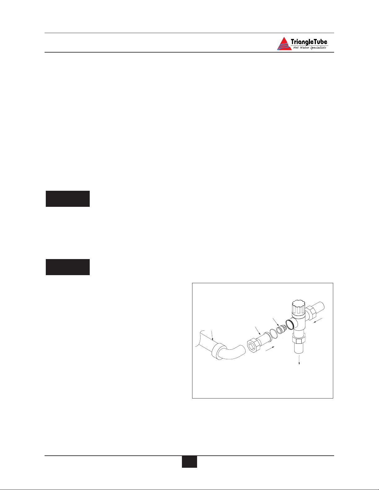
U-Tube Assembly
The ELITE is supplied with a U-Tube
Assembly that directs cold water to the
thermostatic mixing valve.
To install the U-Tube Assembly the
installer must:
1. Disconnect the cold inlet adapter/union
from the thermostatic mixing valve.
2. Using needle-nose pliers remove the
plastic check valve assembly from the
adapter.
DANGER
WARNING
CAUTION
Page 18
Domestic Piping
3. Solder the U-Tube Assembly onto the
adapter. (See Fig. 1)
4. Once the adapter has sufficiently
cooled, re-insert the check valve assembly making sure of orientation and
reconnect onto the mixing valve.
If the installation of the ELITE requires
domestic hot water for a commercial dishwasher, the installer may insert a tee connection between the unit and the mixing
valve to provide 140ºF domestic hot water.
The installer must reference local plumbing
codes to ensure if this type of application is
permissible.
The thermostatic mixing valve MUST be
installed and utilized on the ELITE.
Removal of the thermostatic mixing
valve will result in severe personal injury
or death.
The manual valve on the U-Tube assembly must remain in the full open position
for proper operation of the thermostatic
mixing valve.
Domestic Drain Valve
- The installer must install a drain valve
and drain leg as shown in Fig. 2 page
14 or Fig. 3 page 15.
- The drain valve should be positioned
close to the floor to aid in the siphon
action required to drain the inner tank.
Multiple Units Installation
For applications using multiple units the
domestic piping should be piped using a balanced manifold arrangement.
The installer should remove the thermostatic
mixing valve from the units and install a single
thermostatic mixing valve at the outlet of the
hot water manifold. The thermostatic mixing
valve should be sized according to the required
flow rate and pressure drop. Refer to the thermostat mixing valve manufacturer specification and installation instructions for more
details.
Reference Fig. 4, page 15 for piping diagram.
Storage Tank Application
For applications requiring large volumes of
domestic hot water in a relative short period,
the installer may include a storage type tank
(see Fig. 5 page 16) in the domestic piping.
The installer must:
1. Relocate the thermostatic mixing valve
from the ELITE to the outlet of the storage tank.
2. Provide recirculation from the storage
tank back to the ELITE using a bronze
type circulator. Maximum recommended flow rate is 5 to 10 gpm.
CAUTION
DANGER
13
Fig. 1: Mixing Valve Assembly
Check Valve
U-Tube Assembly
Adapter
Cold
Mixed
ot
H
Page 19

14
Domestic Piping
TR/SMART Series Application
For applications requiring large volumes of
domestic hot water over an extended period,
the installer may include a Triangle Tube
TR/SMART Indirect Water Heater in conjunction with the ELITE. (See Fig. 6 page 16)
The domestic system recirculation, if used, is
directed to the TR/SMART Series Tank. The
circulator should be controlled by an aquastat.
The primary piping to the TR/SMART Series
tank must comply with the piping methods
details in SECTION V - Primary Piping or with
other recognized piping methods.
Additional information regarding domestic and
primary piping can be found in the TR/SMART
Installation Manual.
Fig. 2: ELITE Without Recirculation
Note: All shut off valves shown in
this figure must be shut when siphon
draining the ELITE.
Domestic Piping Diagrams
1. Mixing valve with check valve
3. Shut off valve
4. Backflow preventer or pressure reducing valve*
6. Thermal expansion tank
8. Domestic drain valve
9. Vacuum breaker*
* Optional devices may be required by local Codes
1
To dishwasher if
permitted by codes
U-Tube
assembly
3*
12" Heat trap
3
9
4
3
Cold water
inlet
8
6
Page 20

15
Domestic Piping
Fig. 3: ELITE With Recirculation
1. Mixing valve with check valve
2. Flow check valve
3. Shut off valve
4. Backflow preventer or pressure reducing valve*
6. Thermal expansion tank
7. Circulator (controlled by aquastat)
8. Domestic drain valve
9. Vacuum breaker*
Note: All shut off valves
shown in this figure must be
closed when siphon draining
the ELITE
* Optional devices may be required by local Codes
Fig. 4: Multiple Units Installation With Recirculation
To dishwasher if
permitted by codes
Optional recirculation line
3
2
7
3
1
12" Heat trap
3
8
9
4
6
3
Cold water
inlet
7
1
2
3
Optional recirculation line
12" Heat trap
3
6
8
4
9
inlet
Cold water
3
Page 21

16
Domestic Piping
Fig. 6: ELITE with TR/SMART Indirect Water Heater
Fig. 5 : ELITE with Storage Tank
1. Mixing valve with check valve
2. Flow check valve
3. Shut off valve
4. Backflow preventer or pressure reducing valve*
6. Thermal expansion tank
7. Circulator (controlled by aquastat)
8. Domestic drain valve
9. Vacuum breaker*
Domestic Piping
* Optional devices may be required by local Codes
3
2
7
1
To dishwasher if
permitted by codes
3
1
To dishwasher if
permitted by codes
12" Heat trap
Cold water
3
6
3
8
2
7
3
2
7
12" Heat trap
3
3
9
4
3
9
4
inlet
Cold water
inlet
6
8
Page 22

Primary Piping
SECTION V - Primary Piping
General Piping Requirements
Low Water Cutoff Device
- The ELITE is equipped with a factory
installed pressure switch style Low Water
Cut Off device.
- The minimum operating system pressure
allowable with this device is 10 psig.
- Check local codes which require a low
water cutoff device for compliance of
this device.
Backflow Preventer
- Use a backflow preventer valve in the
make-up water supply to the unit as
required by local codes.
Primary System Piping Applications
All piping applications shown in this installation manual utilize a primary/ secondary
piping arrangement. This method is recommended as a means to provide priority
to the production of domestic hot water.
For other piping arrangements, consult the
Engineering Department at Triangle Tube
or consult other approved/recognized
design arrangements.
On piping applications utilizing a single
zone or other recognized piping design
arrangements it is recommended the
installer uses flow/check valves with
weighted seats at or near the appliance to
prevent gravity circulation.
Expansion Tank and Makeup Water
Ensure the expansion tank is properly sized
for the outer tank volume (22 gallons) and
the system volume and temperature.
Undersized expansion tanks will cause system water to be lost through the pressure
relief valve and cause additional makeup
water to be added to the system. Eventual
primary tank failure can result due to this
excessive makeup water addition.
The expansion tank must be located as
shown in Fig. 7, 7A or 7B page 20 or as per
recognized design methods. Refer to the
expansion tank manufacturer instructions
for additional installation details.
Connect the expansion tank to an air separator only if the air separator is located on
the suction side (inlet) of the system circulator. Always locate and install the system
fill connection at the same location as the
expansion tank connection to the system.
Diaphragm (Bladder) Expansion Tank
Always install an automatic air vent on the
top of the air separator to remove residual
air from the system.
Closed-Type (Standard) Expansion Tank
It is recommended to pitch any horizontal
piping toward the expansion tank 1 inch per
5 feet of piping. Use 3/4” piping for the
expansion tank to allow air within the system to rise.
For proper operation of the expansion tank
and system, remove the factory installed
automatic air vent from the ELITE and
plug the connection. (See Item 10, Fig. 28
page 50)
CAUTION
BEST PRACTICE
BEST PRACTICE
17
Page 23

Primary Piping
DO NOT install automatic air vents on a
closed-type expansion tank system. Air
must remain in the system and be
returned to the expansion tank to provide an air cushion. An automatic air
vent would cause air to be vented from
the system resulting in a water-logged
expansion tank.
Circulator
The ELITE is supplied with a circulator that
is pre-wired to allow for domestic priority.
Locate the circulator in the return or supply
piping as shown in the piping diagrams
included in this manual.
Closet (Zero Clearance) Applications
For applications in closets or zero clearances, the installer may use the upper primary connection shown as Item 4 Fig. 28 on
page 50 as a primary return connection. The
air elimination, expansion tank and make-up
water system should then be piped directly
into the primary loop of the space heating
prior to the system circulator.
Sizing Primary Piping
See Fig. 8 through 11, pages 21 - 22, for
recommended piping arrangements based
on various applications. In all diagrams,
the space heating system is isolated from
the ELITE using primary / secondary piping connections.
Size the piping and system components
required in the space heating system using
recognized design methods.
System Piping - Zone Circulators
Connect the ELITE to the system piping as
shown in Fig. 9 page 21 when zoning with
zone circulators. The circulator supplied
with the ELITE should not be used for a
heat zone. It must supply only the primary loop.
Install a separate circulator for each zone of
space heating.
To control the zone circulators refer to Fig.
19, page 35.
To ensure adequate flow rate through
the ELITE, maintain a minimum 1 inch
diameter on the system piping connecting the unit to and from the primary /
secondary connection.
System Piping - Zone Valves
Connect the ELITE to the system piping as
shown in Fig. 9 page 21 when zoning with
zone valves. The primary / secondary piping ensures the priority is given to the production of domestic hot water.
To control the system zone valve refer to
Fig. 18, page 34.
To ensure adequate flow rate through
the ELITE, maintain a minimum 1 inch
diameter on the system piping connecting the unit to and from the primary /
secondary connection.
System Piping - Radiant Heating with Mixing
Valve
Connect the ELITE to the system piping as
shown with a radiant system using a thermostatic mixing valve as shown in Fig. 11 page
22. The primary / secondary piping ensures
sufficient return temperature to the ELITE.
NOTICE
NOTICE
CAUTION
18
Page 24

19
Primary Piping
If the radiant system tubing contains no
oxygen barrier, a stainless steel heat
exchanger must be used. Failure to
install a heat exchanger could lead to
premature failure of the outer tank and
void any warranty claim.
Radiant heating system piping should
include a means of regulating the boiler
return water. The return water temperature to the unit should be maintained at
130ºF or higher. Failure to prevent low
return water temperature to the unit
could cause premature failure of the unit
and it’s burner system resulting in severe
personal injury, death or substantial
property damage.
Size the system piping and circulator to provide the flow needed for the radiant system.
To control the zone circulators refer to Fig.
19, page 35.
To ensure adequate flow rate through
the ELITE, maintain a minimum 1 inch
diameter on the system piping connecting the unit to and from the primary /
secondary connection.
System Piping - Multiple Units Installation
Use a balance manifold system as the primary / secondary connection to the space
heating piping as shown in Fig. 12 page 23.
Refer to Fig. 7 page 20 to install air elimination and expansion tank.
For the space heating piping refer to the
applications mentioned in this manual or
use recognized design methods.
To ensure adequate flow rate through
the ELITE, maintain a minimum 1 inch
diameter on the system piping connecting the unit to and from the primary /
secondary connection.
NOTICE
NOTICE
WARNING
NOTICE
Page 25

20
Primary Piping
Near Appliance Piping
1. Appliance Circulator
2. Shut Off valve
3. Expansion tank
4. Auto fill valve
5. Tank fitting
6. Automatic air vent
7. Air Separator
8. Plug (by others)
To
system
From system
Supply
flow
Return
flow
Cold Water
fill supply
2
1
7
6
8
2
12"
Max.
3
42
2
2
Fig. 7 : Near Appliance Primary
Piping with a Diaphragm
Type Expansion Tank
Fig. 7A : Near Appliance Primary
Piping with Closed Type Expansion Tank
Fig. 7B : Near Appliance Primary Piping
with Diaphragm - Type Expansion
Tank (Alternate Circulator Location)
3
To
system
2
Supply
flow
12"
Max.
2
6
2
7
8
3
4
From system
2
Cold Water
fill supply
To
system
Supply
flow
12"
2
Max.
2
1
2
2
Return
flow
5
4
7
8
Cold Water
2
fill supply
From system
Return
flow
2
1
Page 26

21
Primary Piping
Fig. 8: Primary piping - Zoning with Circulators
Fig. 9: Primary Piping - Zoning with Zone Valves
1. Appliance circulator
2. Shut-off valves
3. Flow check valve
4. Zone valve
5. System purge valve
6. System circulator
Note: See page 20 for near appliance piping.
• Install balancing valves to
adjust flow to distribute
heat to all zones
• Size primary manifold for
total flow of all circulators
• Size each circulator to individual circuit requirements
• Install balancing valves to
adjust flow to distribute
heat to all zones
6
3
2
2
1
12" max.
2
5
2
2
L
O
A
D
2
3
6
3
2
L
O
A
D
2
3
6
2
1
12" max.
2
4
L
O
A
D
5
4
2
2
2
L
O
A
D
2
Page 27

22
Primary Piping
Fig. 10: Primary Piping - Low Temperature Radiant System
Note: Adjust system temperature
valve to establish maximum supply/return temperature differential of 30ºF and a minimum
130ºF return water temperature
to the ELITE
1. Circulator
2. Shut Off valves
3. Flow check valve
4. Zone valve
5. Purge valve
6. System circulator
7. 3-way mixing valve
8. System Temperature valve (See note above)
Fig. 11: Primary Piping - Multi Temperature System
2
LOAD
6
HMC
3
7
2
8
1
5
2
5
2
2
12" Max.
1
12" Max.
12" Max.
2
2
8
2
6
2
H
2
6
2
Baseboard
Load
3
7
M
C
6
Radiant
3
3
Air Handler
Load
Load
Page 28

23
Primary Piping
1. Unit Circulator
2. Shut Off Valves
3. Flow Check Valve
4. System Circulator
Fig. 12: Primary Piping - Multi Units Installation
System
From the
12"
Max.
4
Recommended placement
of expansion tank and
make up water supply.
e
s
a
h
-
P
I
I
I
e
s
2
3
1
n
h
o
t
t
u
B
h
s
u
e
P
R
o
T
e
s
a
h
-
P
I
I
I
e
s
I
I
I
a
h
P
c
t
i
w
S
t
e
s
I
I
I
a
h
P
h
P
-
h
a
s
e
I
I
I
-
P
h
a
s
e
I
I
I
-
h
P
-
h
a
s
e
I
I
I
h
a
s
e
I
I
I
-
S
p
e
a
a
c
t
e
i
n
g
D
o
m
e
s
t
i
Primary
c
Primary
Hot Water Specialists
TriangleTube
S
p
e
a
a
c
t
e
i
n
g
-
P
D
o
m
e
s
t
i
c
Domestic
Heating
Temperature/Pressure
Heating
To the System
2
S
p
h
e
a
a
c
P
-
t
h
e
I
I
a
i
I
s
n
e
e
s
g
I
a
I
I
h
-
-
P
I
I
I
P
D
h
e
o
a
s
s
m
a
e
h
P
I
I
I
-
e
s
Heating
t
i
Primary
c
Primary
2
3
1
Temperature/Pressure
n
h
o
c
t
t
t
i
u
w
B
S
t
h
e
s
s
u
e
P
R
o
T
Hot Water Specialists
TriangleTube
S
p
h
e
a
a
c
P
-
t
h
I
e
I
a
i
I
s
n
e
e
s
g
I
a
I
I
h
-
-
P
I
I
I
P
D
h
e
o
a
s
s
m
a
e
h
P
I
I
I
-
e
s
t
Heating
i
c
Domestic
2
S
p
h
e
a
a
c
P
-
t
h
e
I
I
a
i
I
s
n
e
e
s
g
I
a
I
I
h
-
-
P
I
I
I
P
D
h
e
o
a
s
s
m
a
e
h
P
I
I
I
-
e
s
Heating
t
i
Primary
c
Primary
2
3
1
Temperature/Pressure
n
h
o
c
t
t
t
i
u
w
B
S
t
h
e
s
s
u
e
P
R
o
T
Hot Water Specialists
TriangleTube
S
p
h
e
a
a
c
P
-
t
h
e
I
I
a
i
I
s
n
e
e
s
g
I
a
I
I
h
-
-
P
I
I
I
P
D
h
e
o
a
s
s
m
a
e
h
P
I
I
I
-
e
s
t
Heating
i
c
Domestic
2
Page 29

24
Venting
SECTION VI - Venting
Oil Vent - General Requirements
Improper installation of vent system
could cause improper draft causing flue
gas leakage and carbon monoxide emissions, which could cause severe personal
injury or death.
Installation must comply with local requirements for oil burning appliances. In absence of
local codes the installer should refer to:
• NFPA 31, Installation of Oil-Burning
Equipment
• NFPA 211, Standard for Chimneys,
Fireplaces, Vents and Solid Fuel
Burning Appliances.
• In Canada, the installer should refer to
CSA B139, Installation Code for OilBurning Equipment.
NFPA 211 requires the chimney to be lined
before connecting to the ELITE appliance.
Inspect existing chimney before
installing the ELITE. Failure to complete the following guidelines will result
in severe personal injury or death:
- Clean the chimney, including
removal of any blockages
- Repair or replace any deteriorating
or damaged vent pipe or liner
- Repair any damaged chimney mortar or joints
The chimney must extend a minimum 3 feet
above the highest point where it passes through
the roof and 2 feet higher than any portion of
the building within 10 feet.
The cross sectional area of the chimney and the
height must be increased at minimum 4% per
1,000 feet of elevation above sea level.
The installer must maintain minimal clearances
from the vent pipe to combustible material as
follows:
-Type “L” doublewall vent - 6 inches
- Single wall vent pipe - 18 inches
The chimney size should be maintained as minimal, oversize chimneys could result in the formation of condensate in the chimney.
Oil Vent Piping
Long horizontal vent runs, excessive
number of tees or elbows or other fittings
that restrict the combustion flue gas flow
can result in potential flue condensation,
flue gas leakage and/or carbon monoxide
emissions, which can lead to severe personal injury or death.
When the burner and the ELITE are properly
installed, the overfire draft on the ELITE should
be approximately (-)0.01”w.c to (-)0.02”w.c.
WARNING
DANGER
WARNING
ELITE Flue Outlet Minimum
Model Diameter Chimney Height
Rectangle Round
F-25
F-30 5 inch 6"
F-35
F-40
F-45
8" x 8"
15 ft
Minimum I=B=R
Chimney Size
Minimum Chimney Size - Oil Fired
7 inch
7"
8" x 8"
15 ft
Page 30

25
Venting
Install a barometric control device in the vent
connector as shown in Fig. 13 and 13A and
adjust per the manufacturer’s instruction when
excess draft needs to be relieved or when
applicable codes require a device.
Install an induced draft fan in the chimney for
applications in which:
- Excessive resistance to the flow of flue
gases is excepted
- The cross-sectional area of the chimney
is smaller than the minimal area
required
- The chimney height is less than the
minimal requirement
When using an induced draft fan the installer
should seal all vent joints and provide an interlock system for the ELITE to ensure fan operation.
Oil Vent - Direct Vent Applications
The installer must read and comply with the
direct vent instruction outline in Triangle Tube
Oil-Fired Direct Vent Instructions.
The installer should give attention to the location of the ELITE prior to installation. The
installer should:
- Locate the unit for shortest possible
vent length and the most direct path to
the outside wall.
- Note that flue gases will form a white
plume in colder climates which may
obstruct window views
- Note that prevailing winds could cause
nuisance lockouts, freezing of condensate and water/ice build-up may occur
on buildings, plants and roofs.
The installer should consider the following
when determining the location of the vent termination:
- Locate or guard the vent termination in
a manner to prevent accidental contact
by people or pets.
-Vent must terminate at least 4 feet
below and 4 feet horizontally or 1 foot
above any window, door or gravity air
inlet to the building.
-Vent must terminate not less than 7 feet
above grade when located adjacent to a
public sidewalk.
-Terminate the vent at least 6 feet from
adjacent walls
- The bottom of the vent termination
shall be located at least 1 foot above the
grade, including normal snowline.
- DO NOT terminate the vent into window wells, stairwells, alcoves, courtyards or other recess area.
- DO NOT terminate vent above any
window, door or gravity inlet as condensate can freeze causing ice formations.
Fig. 13
Fig. 13A
Oil Fired Installations
Damper
Damper
Page 31

Venting
26
Gas Venting -General Requirements
The venting system must be installed in accordance with:
- NFPA 54 National Fuel Gas Code, ANSI
Z223.1.
- NFPA 211 Standard for Chimneys, Vent
and Solid Fuel Burning Appliances.
For installations in Canada the venting system
must be installed in accordance with:
- CGA / B149 Installation Code for Gas
Burning Equipment.
- Prior to installing the appliance into an
existing chimney or venting system, the
vent system should be inspected for
condition and obstructions.
If the inspection reveals the vent system
is not safe for the intended use, it shall be
repaired, rebuilt, lined, relined or
replaced with a vent or chimney to conform to NFPA 211, latest edition. Failure
to conduct such an inspection and/or
repair could result in severe personal
injury, death or substantial property
damage.
- No portion of the venting system shall
extend into or pass through any circulating air duct or furnace plenum.
- The gas venting system shall be
installed, supported and spaced in
accordance with their listings and the
manufacturer’s instructions.
Masonry and Metal Chimneys
- The NFPA code book severely limits the
installation of the ELITE into a masonry
chimney. For applications using either
interior or exterior masonry chimney a
listed, approved metal chimney lining
system should be used.
For any applications using an exterior
chimney it is recommended that an insulated or stainless steel chimney lining
system be used.
A chimney with one or more sides
exposed to the outside of the structure is
considered to be an exterior chimney.
- The chimney shall extend at least 5 feet
above the highest connected appliance
flue collar.
- The chimney shall extend at least 3 feet
above the highest point where it passes
through a roof of a building and at least
2 feet higher than any portion of a
building within a horizontal distance of
10 feet.
Type B Vent Systems
- The vent system should terminate in
accordance with NFPA 54, latest edition, provided the termination is at least
8 feet from a vertical wall or similar
obstruction.
The Type B vent system shall extend in a
general vertical direction with offsets not
exceeding 45 degrees. A vent system
having not more than one 60 degree offset shall be permitted. Any angle greater
than 45 degrees is considered horizontal.
The total horizontal distance of a vent
plus the horizontal vent connector shall
not be greater than 75% of the vertical
height of the vent.
BEST PRACTICE
BEST PRACTICE
NOTICE
BEST PRACTICE
WARNING
Page 32

27
Venting
Vent Connectors
- When a vent connector must be located
in or pass through an un-conditioned
space, attic or crawl space, that portion
of the vent connector must be listed as
Type B or other approved material having equivalent insulation qualities.
- The minimum clearance to combustibles for single wall vent connectors shall be 6 inches.
- The minimum clearance to combustibles for Type B vent connectors
shall be 1 inch or per vent manufacturer’s instructions.
- The vent connector shall be installed in a
manner to avoid excessive turns or other
construction features that create excessive
resistance to the flow of the vent gases.
- The vent connector should be installed in
a manner without any dips or sags and
should slope upward toward the vent or
chimney at least 1/4 inch per 1 foot.
- The location of the appliance should be
located as close to the vent or chimney
to maintain the vent connector length as
short as possible.
The maximum horizontal length allowable should not exceed 75% of the height
of the vent or chimney assuming no offsets in the vertical vent.
- The entire length of a vent connector
shall be readily accessible for inspection, cleaning and replacement.
- The diameter of the vent connector should
not be upsized more than two sizes greater
than the flue outlet diameter.
The vent system must be designed and
installed in compliance with all applicable codes. Failure to properly size and
install the vent system could result in
severe personal injury, death or substantial property damage.
Common Vent Systems
The ELITE may be vented into a common vent
system using the guidelines and sizing Tables
of the National Fuel Gas Code NFPA 54 ANSI
Z223.1 latest edition.
The ELITE may also be vented into a common
multi story vent using the guidelines and sizing
Tables of the National Fuel Gas Code NFPA 54
ANSI Z223.1 latest edition.
WARNING
BEST PRACTICE
Fig. 14
Fig. 14A
Gas Fired Installations
Dual Acting
Barometric
Damper
Dual Acting
Barometric
Damper
Tee (drip leg)
Bottom Cap.
Page 33

28
Fuel Piping
SECTION VII - Fuel Piping
Gas Supply Piping Connection
The gas supply piping must be installed
in accordance to all applicable local,
state and national codes and utility
requirements.
1. Remove the burner jacket hood. Refer to
Fig. 15 to pipe gas supply to the burner.
a. Install a pipe union at the factory sup-
plied gas nipple, for ease of service.
b. Install a manual shutoff valve in the gas
supply piping as shown in Fig. 15. For
installations in Canada the installer
must tag and identify the main shutoff
valve.
c. Install a drip leg on the gas supply line
prior to connecting to the ELITE gas
train as shown in Fig. 15.
2. Support the gas piping using hangers. Do
not support the piping by the unit or its
components.
3. Purge all air from the gas supply piping.
4. Before placing the ELITE into operation,
check and test all connections for leaks.
Close the manual shutoff valve during
any pressure test with less than 13”w.c..
Disconnect the ELITE and its gas valve
from the gas supply piping during any
pressure test greater than 13”w.c..
Do not check for gas leaks with an open
flame. Use a gas detection device or bubble test. Failure to check for gas leaks
can cause severe personal injury, death
or substantial property damage.
5. Use pipe dope compatible with natural and
propane gases. Apply sparingly only to the
male threads of pipe joints so that pipe
dope does not block gas flow.
Failure to apply pipe dope as detailed
above can result in severe personal
injury, death or substantial property
damage.
Use a two-wrench method of tightening
gas piping near the unit and its gas valve.
Use one wrench to prevent the gas valve
line connection from turning and the second to tighten adjacent piping. Failure
to support the gas valve connection piping could damage the valve and the gas
line components.
WARNING
WARNING
WARNING
NOTICE
Fig. 15: Recommended Gas Supply Piping
Page 34

29
Fuel Piping
Pipe Sizing - Natural Gas
1. Refer to Table 1 for pipe length and diameter requirements. Based on rated ELITE
input (divide by 1,000 to obtain cubic feet
per hour).
-Table 1 is based on Natural Gas with a
specific gravity of 0.60 and a pressure
drop through the gas piping of
0.30”w.c..
- For additional gas piping sizing infor-
mation, refer to ANSI Z223.1. For
Canadian installations refer to B149.1
or B149.2.
Natural Gas Supply Pressure Requirements
1. Pressure required at the gas valve inlet
supply pressure port:
- Maximum 13”w.c. at flow or no flow
conditions to the burner.
- Minimum 5”w.c. during flow condi-
tions to the burner. Must be verified
during start up.
2. Install 100% lockup gas pressure regulator
in the gas supply line if inlet pressure can
exceed 13”w.c at any time. Adjust the lockup pressure regulator for 13”w.c maximum.
Pipe Sizing - Propane Gas
1. Contact the local propane gas supplier for
recommended sizing of piping, tanks and
100% lockup gas regulator.
Propane Gas Supply Pressure Requirements
1. Adjust the propane supply regulator provided by the gas supplier for 13”w.c. maximum pressure
2. Pressure required at the gas valve inlet supply pressure port:
- Maximum 13”w.c. at flow or no flow
conditions to the burner
- Minimum 5”w.c. during flow condi-
tions to the burner. Must be verified
during start up.
Length of Pipe
in Feet
SCH 40 1/2" 3/4" 1" 1-1/4" 1-1/2"
10 132 278 520 1050 1600
20 92 190 350 730 1100
30 73 152 285 590 860
40 63 130 245 500 760
50 56 115 215 440 670
75 45 93 175 360 545
100 38 79 150 305 460
150 31 64 120 250 380
Capacity of Pipe in Cubic Feet of Gas Per Hour
(based on 0.60 specific gravity, 0.30" w.c. pressure drop)
Table 1: Gas piping sizing - Natural Gas
Page 35

30
Fuel Piping
General Oil Piping Guidelines
Location and installation of oil tanks, oil piping
and burners must comply with:
- NFPA 31, Standard for the Installation
of Oil-Burning Equipment
- Local codes and regulations
- Manufacturer’s information provided
with the burner and oil pump.
For installations in Canada, CSA B139,
Installation of Oil-Burning Equipment
If the fuel tank is installed or any part of the
fuel tank is above the level of the burner, an
anti-siphon device must be installed to prevent
the spillage of oil in the event of an oil line
break.
Support oil line as required by local codes.
All tank connections should be made using
swing joints or copper tubing to prevent possible line breakage in the event of tank settlement. When using swing joints ensure they are
made to tighten as the tank settles. All thread
connections should be made with a non-hardening pipe joint compound.
Do not use Teflon tape to seal any oil connections. Teflon tape can cause oil valves
to fail, creating potential hazards. Do
not use compression type fittings at the
burner all fittings should be flare type.
WARNING
Page 36

31
Internal Wiring
SECTION VIII - Internal Wiring
ELECTRICAL SHOCK HAZARD. For
your safety, disconnect electrical power
supply to the unit before servicing or
making any electrical connections to
avoid possible electric shock hazard.
Failure to do so can cause severe personal injury or death.
All electrical contacts shown in Figures
15 & 16 pages 31 & 32 do not have electrical power applied. Shown as “offshelf” condition.
General Requirements
-Wiring must be N.E.C Class 1.
-If original wiring as supplied with the
unit must be replaced, use only type
90ºC wire or equivalent.
- The ELITE must be electrically
grounded as required by National
Electrical Code ANSI/NFPA 70 - latest
edition.
NOTICE
WARNING
Fig. 15: ELITE Factory Internal Wiring
R2A
BB
120 VAC
B
B
3
H
On-Off
Switch
Manual
Reset
Limit
1
W
Circulator
N
H
Wire Color Code
Equipment
Ground
2
Burner Control
4
Br
120V
24V
Y
Primary
T-Stat
Secondary
T-Stat
Y
B
5
LWCO
R1A
r
Y
B
7
Factory
Jumper
W
BL
Room T-Stat
Snap-Set
BB
OR
V
9
BL
10
Factory
Jumper
BL
BL
R2B
12
12
BL
T
13
PP
11
Auto
Reset
Limit
R2
T
V
14
R1
6
V
V
Page 37

32
Internal Wiring
Fig. 16: Factory Wiring Schematic
Relay R2
BL
1
B
4
T
BL
3
B
6
T
T
Room T-Stat
Snap-Set
C
B
B
1
Relay R1
1
4
V
LWCO
B
B
3
6
V
R
BL
BL
Burner
W
B
Transformer
BL
B
Y
B
Y
V
Circulator
Y
B
W
G
B
B
Wire Color Code
Y
O
BL
1
C
2
Secondary T-Stat
2
4
P
1
3
2
Y
G
C
2
Primary T-Stat
1G
V
1
W
G
G
G
B
G
120V Incoming
N
Supply Wiring
H
120V Field Wiring (by others)
120V Factory Wiring
T
14
G
13 12
11
9
10
Manual Reset
Safety Limit
8
765
Safety Limit
P
C
Auto Reset
24V Factory Wiring
On-Off
Switch
Page 38

33
External Wiring
SECTION IX - External Wiring
Installation Compliance
All field wiring made during installation must
comply with:
- National Electrical Code NFPA 70 and
any other national, state, provincial or
local codes or requirements.
- In Canada, CSA C22.1 Canadian
Electrical Code Part 1, and any other
local codes.
Line Voltage Connections
1. Connect 120 VAC power wire to the line
voltage leads located behind the front control panel.
2. Route the incoming 120 VAC power wire
through the right side jacket panel.
3. Use the wire nuts provided to ensure a tight
and secure connection.
4. The unit is provided with a service switch,
check local code requirements for compliance.
If local electrical codes or conditions
require an additional service switch, the
installer must provide and install a fused
disconnect or 15 amp (minimum) service
switch.
Thermostat Wiring
1. Connect room thermostat or the end switch
(isolated contact only) of a relay control
panel to the Room Thermostat Snap-set
located on the rear jacket panel.
2. Remove the snap-set cover and connect the
thermostat wiring to terminals C and 1 per
Fig. 17.
3. For proper operation install the room thermostat on an inside wall away from influ-
ences of heat and cold, i.e. water pipes,
areas of draft, lighting fixtures and fireplaces.
4. Set the thermostat anticipator (if applicable) as follows:
- Set for 0.2 amps when wired directly to
the Room Thermostat Snap-set.
- Set to match the total electrical power
requirements of the connected devices
when wired to zone relays or other
devices. Refer to the relay manufacturers’ specifications and the thermostat
instructions for additional information
on the anticipator setting.
Outdoor Temperature Limit
1. The ELITE may operate with a variable
primary operating temperature using an
outdoor reset control provided by the
installer.
2. Remove the factory jumper across terminals 9 and 10 of the wiring terminal.
Connect the outdoor limit control to those
terminals.
3. Set the operating limits of the outdoor limit
control as follows:
- Maximum operating temperature of
180ºF.
- Minimum operating temperature of
150ºF.
NOTICE
Fig. 17: Room Thermostat Snap-set Wiring
Page 39

External Wiring
34
4 Wire Zone Valve
Fig. 18: Multiple Zone Field Wiring Using Zone Valves
3 Wire Zone Valve
*Use isolation relay on 3-wire
zone valve with non-isolated
end switch. Transformer and
the ELITE control can burn out
if isolation relay is not used.
High Voltage
V.A.C.
24
V.A.C.
Room
Thermostat
Room
Thermostat
Zone 1
Zone 2
Additional zones
Additional zones may
be added as shown above
To ELITE
"Room Thermostat"
Snap Set
Transformer
(Power)
Zone
Valve
Zone Valve
C
1
H
120
V.A.C.
H
High Voltage
Transformer
(Power)
24
V.A.C.
Room
Zone Valve
Zone 1
Thermostat
Zone 2
Room
Thermostat
Zone
Valve
Additional zones
Additional zones may
be added as shown above
* Isolation relay
1
C
To ELITE
"Room Thermostat"
Snap Set
Page 40

35
External Wiring
Fig. 19: Field wiring with zone circulators.
120
H
VA C
N
Honeywell
R845A
Relay
Circulator
Zone 1
TT
T
T
1
2
T
T
1
2
Thermostat
zone 1
4
3
Thermostat
zone 2
4
3
5
6
5
6
Circulator
Zone 2
Additional zones may be
added as shown above
1
C
To ELITE
" Room Thermostat"
Snap Set
Page 41

36
External Wiring
Fig. 20: Typical Zone Relay Panel Wiring
Fig. 21: Storage Tank Recirculation Wiring
N
120V
H
C
ELITE
"Room Thermostat"
Snap-Set
Thermostat
Zone 1
R
C
T1 T1 T2T2 T3 T3
X2X1L1L2 ZC
1
Zone 1
Circulator
Thermostat
Zone 2
C2C2C1C1PRPR
Zone 2
Circulator
Thermostat
Zone 3
C3
C3
Zone 3
Circulator
TT
T
120
VA C
H
N
2
Bronze
Circulator
Storage Tank
Thermostat
T
1
4
Honeywell
R845A
Relay
3
5
6
Page 42

37
Start-Up Preparation
4. Set the primary thermostat to the highest
possible setting.
SECTION X - Start Up Preparation
Check System and Domestic Water
Chemistry
Do not use petroleum-base cleaning or
sealing compounds in the primary system. Damage to seals and gaskets in the
system components could occur, resulting in substantial property damage.
System water including additives must be
practically non-toxic, having a toxicity
rating or Class of 1, as listed in Clinical
Toxicology of Commercial Products.
Water pH Level 6.0 to 8.0
Maintain the primary system water pH
between 6.0 and 8.0. Check using litmus
paper or contact a water treatment company for a chemical analysis.
If the pH does not meet this requirement,
do not operate the ELITE or leave the unit
filled until the condition is corrected.
Water Hardness Less Than 7 Grains
For areas with unusually hard water (hardness above 7 grains) consult a water treatment company.
Chloride Concentration Less Than 80 mg/L
For those installations that use a water softener or conditioner, consult the water treatment company.
Any water conditioning system must
be installed and maintained in accordance with the water conditioner’s
manufacturer’s specifications and
within the operating guidelines of the
ELITE.
Chlorinated Water
Do not use the ELITE inner or outer tank to
heat a swimming pool or spa directly.
Maintain the chlorine level of the water in
the inner and outer tanks at levels considered safe for drinking.
Flush Primary and Domestic System to
Remove Sediment
The installer must flush both the primary
and domestic system to remove any sediment to allow proper operation of the
ELITE.
Flush the systems until the water runs clean
and is free of sediment.
For primary zoned systems, each zone
should be flushed through a purge valve.
Purge valves and isolation valves should be
installed on each zone to allow for proper
flushing of the system.
Check and Test Antifreeze
For primary systems containing antifreeze
solutions, follow the antifreeze manufacturer’s instructions in verifying the
inhibitor level and to ensure the fluid characteristics are within specification requirements.
Due to the degradation of inhibitors over
time, antifreeze fluids must be periodically
replaced. Refer to the manufacturer of the
antifreeze for additional instructions.
NOTICE
NOTICE
WARNING
Page 43

Start-Up Preparation
38
System water including additives must be
practically non-toxic, having a toxicity
rating or Class of 1, as listed in Clinical
Toxicology of Commercial Products.
Use of Antifreeze in the Primary System
NEVER use automotive or ethylene glycol antifreeze or undiluted antifreeze in
the primary system as freeze protection.
This can cause severe personal injury,
death or substantial property damage if
ignored.
Determine the antifreeze fluid quantity
using the system water content volume and
following the antifreeze manufacturer
instructions.
The primary outer tank volume of the
ELITE is 20 gallons. Remember to include
the volume of the expansion tank.
Check with local codes requirements for
the installation of back flow preventers or
actual disconnect from the make up water
supply line.
Ensure the concentration of antifreeze to
water does not exceed a 50/50 ratio.
System water including additives must be
practically non-toxic, having a toxicity
rating or Class of 1, as listed in Clinical
Toxicology of Commercial Products.
Filling the Inner (Domestic) Tank and
System
Proceed with filling instructions for the
inner and outer tanks only after ensuring the water meets the requirements
listed in this installation manual. Failure
to comply could result in damage and
improper operation of the unit.
Never operate the ELITE unless both the
inner and outer tanks are completely
filled.
Always fill the inner tank prior to filling
and pressurizing the outer tank. Failure
to properly fill the inner tank could
result in damage to the inner tank.
1. Ensure the domestic drain valve is closed.
2. Open the isolation valves on the domestic
cold supply piping to the ELITE and on the
domestic hot outlet piping to the building.
3. Vent any air from the domestic piping system by opening faucets near the unit.
Continue filling the domestic system until
there is a constant flow of water from the
faucets.
4. Close the hot water faucets.
Filling the Outer (Primary) Tank and
System
1. Close the primary drain valve located
on the rear of the unit and any manual
or automatic air vent in the system.
2. Open all system isolation valves.
CAUTION
CAUTION
WARNING
NOTICE
WARNING
NOTICE
Page 44

39
Start-Up Preparation
3. Fill the outer tank to correct system
pressure. Correct pressure will vary
with each application.
Typical residential system fill pressure is
12 psi. System pressure will increase
when system temperature increases.
Operating pressure of the system should
never exceed 25 psi.
4. Allow air to escape from the outer tank by
opening the automatic air vent provided
with the ELITE.
5. Purge air in each zone of the primary system through the purge valve. Open air
vents to allow air to be purged in the zones.
6. Once the system is completely filled and
purged of all air, check the system pressure
and check for leaks.
Check Low Water Cut-Off Device
- The ELITE is provided with a factory
installed Low Water Cut-Off device
that measures system pressure of more
than 10 psi.
- Remove the front jacket panel and
check for continuity across the low
water cut-off device wire terminals.
The contacts should be closed when system pressure is greater than 10 psi.
Check For Gas Leaks (if applicable)
Prior to start-up and during initial operation, smell near the floor and around the
unit for gas odorant or any unusual odor.
Do not proceed with the start-up if there
is any indication of a gas leak. Any leaks
found must be repaired immediately.
Propane installations only - The propane
supplier mixes an odorant with the
propane to make its presence detectable.
In some cases the odorant can fade and
the gas may no longer have an odor.
Prior to start-up of the unit and periodically after start-up have the propane
supplier check and verify the odorant
level.
Check Thermostat Circuit
- Unplug the Room Thermostat Snap-set
located on the rear of the unit.
- Connect a voltmeter across the end terminals of the male half of the Room
Thermostat Snap-set.
- Close each thermostat, zone valve and
relay in the external circuit one zone at
a time and check the voltage reading
across the plug.
- There should NEVER be voltage measured at the plug.
- If voltage is measured at the plug under
any condition, check and correct the
external wiring.
In systems using 3-wire zone valves
backfeed of voltage to the unit is a common problem. Use an isolation relay to
prevent voltage from the external circuit
entering the Room Thermostat Snapset.
NOTICE
WARNING
WARNING
NOTICE
Page 45

40
Start-Up Procedures
SECTION XI - Start-Up Procedures
Final Checks Before Start-up
Verify the ELITE and the primary and
domestic systems are full of water and
all system components are correctly set
for operation.
Verify Start-up Preparation items outlined
on pages 37 thru 39 have been completed.
Verify all electrical connections are
correct and securely fasten.
Inspect vent piping and combustion air
inlet piping for signs of deterioration from
corrosion, physical damage or sagging.
Verify combustion air piping and vent piping are intact and correctly installed.
Adjustment of the Secondary Thermostat
Limit.
The Secondary (Domestic) Thermostat
located on left side of the control panel
maintains the minimum domestic water
storage temperature.
Set the thermostat knob as shown in
Fig. 22 page 42.
Maximum limit setting is 140ºF
ELITE Start-up
Turn the ON-OFF switch located on the
front control panel to the OFF position.
Turn the electrical supply or any service
switch to the unit in the ON position.
Check Domestic Piping.
Check domestic piping and system
components for leaks. If found, shut
down the unit and repair immediately.
Check Primary Piping.
Check primary system piping and components for leaks. If found, shut down
the unit and repair immediately.
Purge any remaining air from the system
piping. Air in the system piping will
interfere with circulation creating heat
distribution problems and system noise.
Check Vent Piping
Check for gas-tight seal at every connection and seam of the venting.
Venting system must be sealed gas-tight
to prevent flue gas spillage and potential
carbon monoxide emissions, which will
result in severe personal injury or death.
Check Gas Piping (if applicable)
1. Check around the unit for gas odor following the procedure outlined in this
manual on Page 39.
If any gas leaks are found or suspected,
shut the unit down immediately. Use a
gas detection device or bubble test to
locate the source of the gas leak and
repair at once. Do not operate the unit
until the leak is corrected. Failure to
comply with this procedure could result
in severe personal injury, death or substantial property damage.
Check Oil piping (if applicable)
Check for any leakage at the pump and
all fittings
Verify Flame Pattern and Combustion
Check the flame pattern through the
inspection port of the burner. The
flame should be stable.
Test for CO2 or O2 and for CO. The
combustion reading should be within
the range listed in Table 2 page 41. The
CO level should not exceed 100 ppm
when combustion is correct.
WARNING
WARNING
Page 46
41
Start-Up Procedures
A combustion test must be performed
after any burner adjustments are made.
Allow the unit to operate for approximately 10 minutes after adjustment
before measuring any combustion levels.
Failure to comply with these procedures
could result in severe personal injury,
death or substantial property damage.
Check overfire draft
The overfire draft should measure typically (-) 0.01” w.c to(-) 0.02” w.c in the
combustion chamber. Refer to Triangle
Tube’s Burner Specification for actual
measurements.
Measure Input - Natural Gas Only
1. Operate the unit for approximately 10
minutes.
2. Turn off all gas appliances within the
building.
3. At the gas meter, record the time
required to use one cubic foot of gas.
4. Calculate gas input using the following
equation:
3600 x 1000 / number of second recorded for one cubic of gas = BTU/H.
5. The BTU/H calculated should approximate the input rating listed on the unit.
WARNING
Natural Gas Propane Oil
O2 Min. 3.00% 3.00% 4.60%
O2 Max. 5.00% 5.00% 6.00%
CO2 Min 9.00% 10.50% 11.00%
CO2 Max 10.00% 12.00% 12.00%
Table 2: Recommended Combustion Levels
Page 47
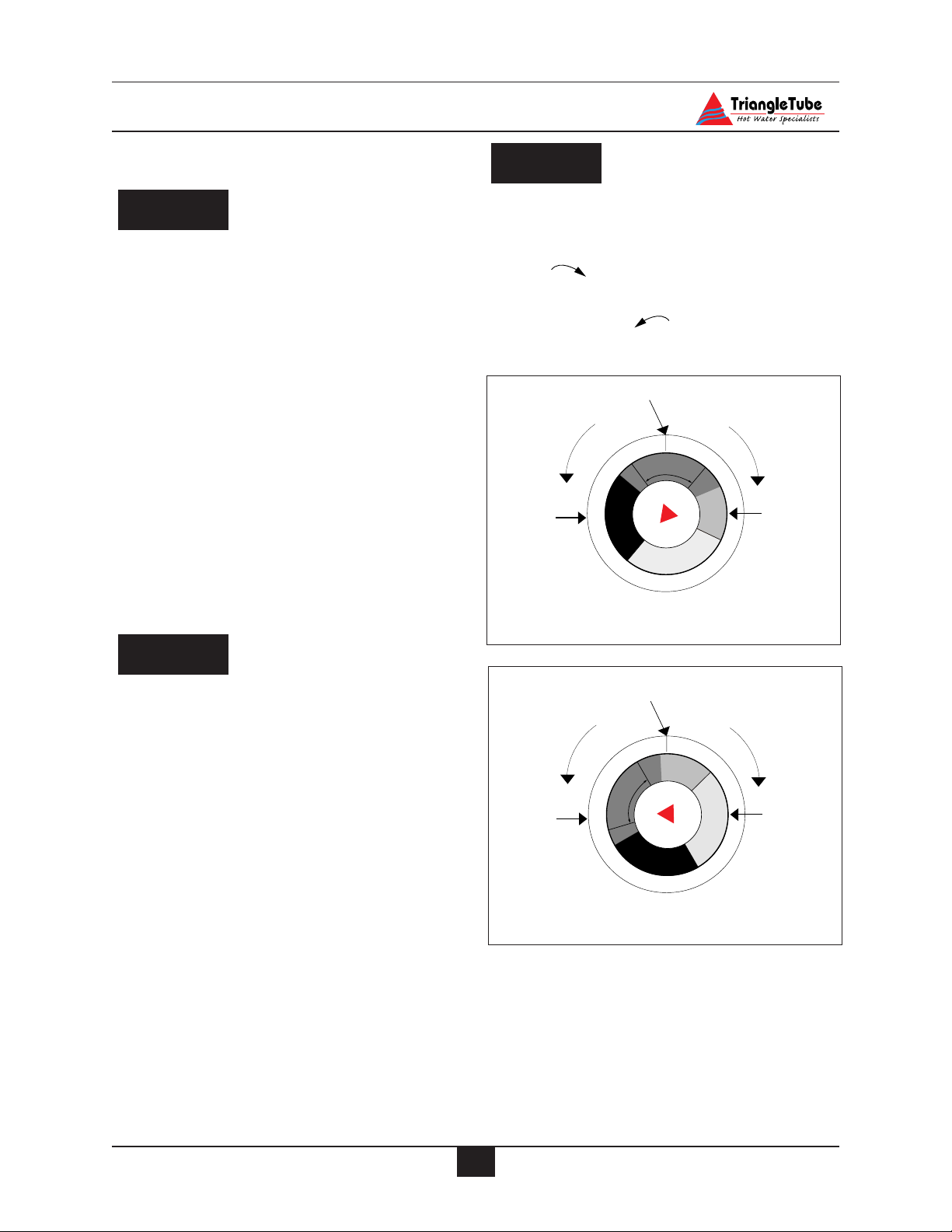
42
Temperature Limits
SECTION XII - Temperature Limits
Studies have indicated that dangerous
bacteria can form in the potable water
distribution system if certain minimum
water temperatures are not maintained.
For prevention of this, it is recommended that the Secondary Thermostat be set
as shown in Fig. 23 and maintained at
130ºF to 140ºF.
Setting Primary Thermostat Limit.
- The Primary (Space Heating) Thermostat
located on the right side of the control
panel acts as the high limit during the
space heating function.
- Set the thermostat knob as shown in
Fig. 22.
- Maximum limit setting is 180ºF
To ensure proper function of the limits
the Primary Thermostat must be set
higher than the Secondary Thermostat.
Adjustment of Secondary Thermostat Limit
- The Secondary (Domestic) Thermostat
located on left side of the control panel
maintains the minimum domestic water
storage temperature.
- Set the thermostat knob as shown in
Fig. 23.
- Maximum limit setting is 140ºF.
To adjust the thermostat settings:
-Turn thermostat knob clockwise
to increase water temperature
-Turn thermostat knob counter-
clockwise to decrease water
temperature.
NOTICE
NOTICE
DANGER
Fig. 23: Recommended Secondary
Thermostat Setting
Fig. 22: Recommended Primary Thermostat
Setting
Temperature Indicator
Temperature UpTemperature Down
a
c
p
e
S
t
a
i
n
e
g
h
D
e
I
I
o
s
I
a
-
Back
Plate
h
P
-
I
I
I
e
s
a
h
P
-
I
I
I
m
P
h
e
a
s
s
t
e
i
c
I
I
I
-
P
h
a
s
e
Knob
Temperature Indicator
Temperature UpTemperature Down
e
m
s
t
o
i
c
D
g
e
a
s
h
e
P
n
Back
Plate
c
i
a
t
a
p
e
S
h
I
I
-
I
I
-
I
I
e
s
a
P
h
a
h
s
e
P
I
I
-
I
I
-
P
I
I
h
a
e
s
Knob
Page 48

43
Temperature Limits
Setting the Thermostatic Mixing Valve
The thermostatic mixing valve controls
the outlet hot water temperature delivered to the faucets.
POTENTIAL SCALD HAZARD The
mixing valve must be installed on the
ELITE. Removal of the mixing valve
will create a potential scald hazard
resulting in severe personal injury or
death.
If any adjustment needs to be made on the
valve:
- Use a L-Key to remove the set screw
securing the knob to the valve.
- Remove the knob and lock ring from
the valve.
- Replace the knob and adjust the set
temperature of the valve to the desired
temperature.
To calibrate the outlet temperature,
allow the water to run for approximately
2 minutes and measure the water with a
thermometer. To adjust the valve setting,
rotate the knob clockwise to decrease the
water temperature or counter-clockwise
to increase the water temperature.
- Once the desired temperature is
achieved, remove the knob and refit the
lock ring onto the valve aligning the
ring indicator mark with the valve’s
“Mix” marking.
- Locate the tab on the inner face of the
knob into the retainer in the locking
ring. Secure the knob with setscrew.
- Record the valve performance on the
Installation Record included in this
manual.
For proper operation of the thermostatic
mixing valve, the manual valve on the Utube assembly MUST remain open to
avoid a potential scald hazard.
DANGER
NOTICE
WARNING
NOTICE
Page 49

44
Check-Out Procedures
SECTION XIII- Check-Out Procedures
Perform the following check-out procedures as outlined and check off items as
completed. When procedures are completed, the installer should complete the
installation record on page 45.
Check-out Procedures
Both inner and outer tanks filled with
water.
Water chemistry checked and verified
as outlined on page 37.
The automatic air vent on the unit and
any place within the system are open
one full turn.
Air is purged from the heating zones
and primary system.
Domestic piping is purged of air and
has been checked for leaks.
Thermostat circuit wiring checked and
verified that no voltage is present to the
Room Thermostat Snap-set as outlined
on page 39.
Combustion levels and flame pattern
verified as outlined on page 40.
Measure the rate of input on Natural
Gas as outlined on page 41.
Primary and Secondary Thermostat
properly set as shown in Fig. 22 and 23
page 42.
The thermostatic mixing valve adjusted
to the desired domestic hot outlet temperature.
Adjusted balancing valves and system
limit controls to provide design temperatures to the primary space heating system.
In multiple zone applications, adjusted
for correct flow of primary heating
water to each zone.
Check and verified room thermostat
function properly and the thermostat
heat anticipator (if used) was properly
set.
Observed several operating cycles for
proper operation of the ELITE and the
system.
Set the room thermostat(s) to the
desired room temperature.
Reviewed all instructions shipped with
the ELITE with the homeowner or
maintenance personnel.
Complete the Installation Record on
page 45.
Ensure all manuals and other documen-
tation are returned to the Installation
envelope and given to the owner for
safekeeping.
NOTICE
Page 50

45
Installation Record
SECTION XIV - Installation Record
Measured Rate of Input:
Thermostatic Mixing Valve Setting:
Measured Domestic Outlet Temperature:
Combustion Readings:
2
CO
O2
CO
The following items were completed during installation:
Installation instructions have been followed and completed
Check-out procedures have been followed and completed
Information regarding the unit and installation received and left with owner / maintenance
personal.
Installer Information
(Company)
%
%
ppm psig
____________________________________________________________________
Nozzle Size
Nozzle Angle
Pump Pressure
gph
(Address)
(Address)
(Phone Number)
____________________________________________________________________
____________________________________________________________________
_________________________________________________________________
Page 51

46
Replacements Parts
SECTION XVII - Replacement Parts
Replacement Parts
Replacement parts can be ordered and
purchased through a local Triangle Tube
distributor. When ordering parts, specify the Model Number and Serial
Number. Include a description of the
part and a replacement part number.
Using modified or other manufacturer
parts will not be covered by warranty
and may damage or cause improper
function of the unit.
Refer to pages 47 and 49 for description
and replacement part numbers.
NOTICE
WARNING
Page 52

Replacements Parts
47
Fig. 24: Jacket Components
Item Part No. Description Quantity required by Model
F-25/ 30/35/40 F-45
HMJKTF25 Complete Jacket Set 1
HMJKTF40 Complete Jacket Set 1
HMJKT25F Jacket, Front 1
HMJKT40F Jacket, Front 1
HMJKT25L Jacket, Left side 1
HMJKT40L Jacket, Left side 1
HMJKT25R Jacket, Right side 1
HMJKT40R Jacket, Right side 1
HMJKT25B Jacket , Back 1
HMJKT40B Jacket , Back 1
HMJKT25TOP Jacket, Top cover 1
HMJKT40TOP Jacket, Top cover 1
6 PGRKIT20 Low Water Cut-Off Device LWCO 1 1
7 Burner Mounting Plate 1 1
7 HMINS04 Burner Plate Insulation 1 1
51234
HMHOO0611
Burner Jacket Panel
2
4
6
1
3
8
7
5
Page 53

48
Replacements Parts
Item Part No. Description
Operating Thermostat
Primary or Secondary
Manual Reset Hight Limit
Pre-set at 205ºF
Auto Reset High Limit
Pre-Set at 194ºF
Temperature / Pressure
Gauge
Control Panel
PGRKIT21
PGRKIT 22
HMCS01
PGRKIT23
HMGAU01
7118910
Fig. 25: Control Panel Components
9
11
8
7
10
7
Page 54

49
Replacements Parts
Item Part No. Description
R1 Relay - Controls
Burner Function
R2 Relay - Controls
Domestic Priority & Circulator
120 V-24 V 40VA
Transformer
13
PGRKIT18
12A
PGRKIT19
12B
PGRKIT 19
Fig. 26: Electrical Panel Components
Part No. Description
HMRLV01 Pressure Relief Valve 30 psi
P3AVT01 Air Vent
HMVLV07 Thermostatic Mixing valve 3/4"
HNSNP02 Snap sets Male / Female
HMTPV01 Temperature/Pressure Relief Valve (PG PLUS-30/35/40/45 only)
HMTPV03 Temperature/Pressure Relief Valve (PG PLUS-25 only)
12B
14
13
12A
12
11
10
9
8
24V Circuit
7
6
5
4
3
13
2
1
G
120 V Circuit
Page 55

Specifications
50
Fig. 28: Rear view
Fig. 27: Side view
1. Primary circuit, ø 1” NPT
2. Primary circuit drain valve connection, ø 1/2” NPT
3. Domestic temperature/pressure relief valve (150
psi), ø 3/4” NPT
4. Primary circuit & pressure relief valve (30 psi), ø 1”
NPT
5. Domestic cold water inlet, ø 3/4” NPT
6. Hot water outlet & secondary thermostat sensor, ø
3/4” NPT
7. Manual reset safety sensor & pressure indicator sensor, ø 3/4” NPT
8. Primary thermostat sensor, temperature indicator
sensor and automatic reset safety sensor, ø 1/2” NPT
9. L.W.C.O. pressure sensor, ø 1/2” NPT (shown as
Item 6 on page 47)
10. Primary circuit & air vent, ø 1” NPT
Fig. 29: Top view of ELITE
13" Approx.
11"
C
10
Domestic
A
cold
5
D
H
E
G
B
3
4
Domestic
hot
6
F
1
2
J
6
7
4
3
10
5
8
Page 56

Specifications
51
Table 4: ELITE Data
Table 3: Dimensional Data
Graph 1: ELITE Pressure Loss - Primary Side
Model 10 Min. Peak 1st Hour Continuous Flow
Flow Rating @ 80ºF Rise
(gallons) (gallons) (gph)
F-25 56 163 128
F-30 61 188 153
F-35 65 214 179
F-40 74 249 210
F-45 81 292 254
Type F-25 F-30 F-35 F-40 F-45
Input Nat. Gas Btu/hr 100,000 120,000 140,000 165,000 199,000
Inner Tank Capacity Gal 20 20 20 22 22
Outer Tank Capacity Gal 22 22 22 18 18
Dimensions Inches
A5959596767
B2121212121
C2222222222
D 54.5 54.5 54.5 60.5 60.5
E1414141414
F54545462.5 62.5
G 88888
H 11.5 11.5 11.5 11.5 11.5
J 55555
Vent size 55577
Connections:
TP Valve (domestic) 3/4" 3/4" 3/4" 3/4" 3/4"
Domestic water ø 3/4" 3/4" 3/4" 3/4" 3/4"
Primary connection ø 1 " 1 " 1 " 1 1/4 " 1 1/4 "
Drain ø 1/2" 1/2" 1/2" 1/2" 1/2"
Empty weight lb 345 345 345 485 485
Heat exchanger surface Sq. Ft. 17 17 17 26.5 26.5
7
6
5
4
3
Head Loss (Ft.)
2
1
4
2
8
6
Flow Rate (gpm)
10
12
14
16
Page 57
Additional quality water heating equipment available
from
Triangle Tube/Phase III
- Exclusive “Tank-in-Tank” design
-Stainless steel construction
-Available in 8 sizes and 2 models
- Limited LIFETIME residential warranty
- 15 year limited commercial warranty
- Self cleaning/self descaling design
- Construction of high quality corrosion resistant stainless steel (AISI 316)
- Specially designed built-in flow restrictor to assure
maximum heat exchange
- Compact and light weight
-Available in 5 sizes that can accommodate any size
pool or spa
TTP Brazed Plate Heat Exchangers
- For domestic water, snow melting, radiant floor,
refrigeration
- Plates made of stainless steel, with a 99.9 % copper
and brazed, ensuring a high resistance to corrosion
- Self cleaning and self descaling
- Computerized sizing available from Triangle
Tube/Phase III
-Available in capacities from 25,000 BTU/hr to
5,000,000 BTU/hr
Phase III Indirect Fired Water Heaters
Maxi-flo Pool and Spa Heat Exchangers
Freeway Center - 1 Triangle Lane - Blackwood, NJ 08012
Tel: (856) 228 8881 - Fax: (856) 228 3584
http://www.triangle tube.com
E-mail: Info@triangle tube.com
Member of
Group
 Loading...