

Page 1
INSTRUCTIONS
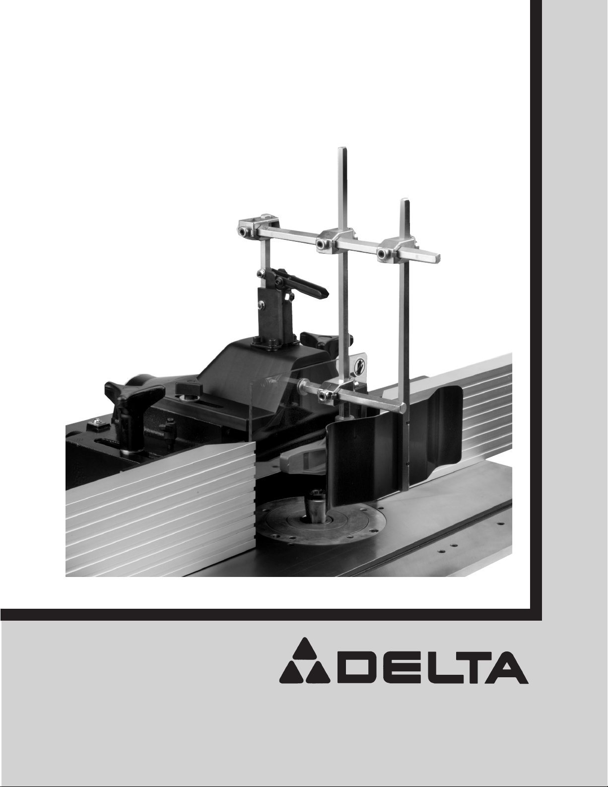
Deluxe Shaper Fence
(Model 43-812)
(Model 43-812X)
PART NO. 432-02-651-0039 - 06-09-03
Copyright © 2003 Delta Machinery
To learn more about DELTA MACHINERY
visit our website at: www.deltamachinery.com.
For Parts, Service, Warranty or other Assistance,
please call
1-800-223-7278 (In Canada call 1-800-463-3582).
Page 2
2
Indicates an imminently hazardous situation which, if not avoided, will result in death or serious injury.
Indicates a potentially hazardous situation which, if not avoided, could result in death or serious injury.
Indicates a potentially hazardous situation which, if not avoided, may result in minor or moderate injury.
Used without the safety alert symbol indicates potentially hazardous situation which, if not avoided, may
result in property damage.
This manual contains information that is important for you to know and understand. This information relates to protecting YOUR SAFETY and PREVENTING EQUIPMENT PROBLEMS. To help you recognize this information, we use the
symbols to the right. Please read the manual and pay attention to these sections.
SAFETY GUIDELINES - DEFINITIONS
NOTICE: THE MANUAL COVER PHOTO ILLUSTRATES THE MODEL 43-812. ALL OTHER ILLUSTRATIONS ARE
OF THE 43-812 WITH THE EXCEPTION OF THE 43-812X CARTON CONTENTS AND FIG 3A.
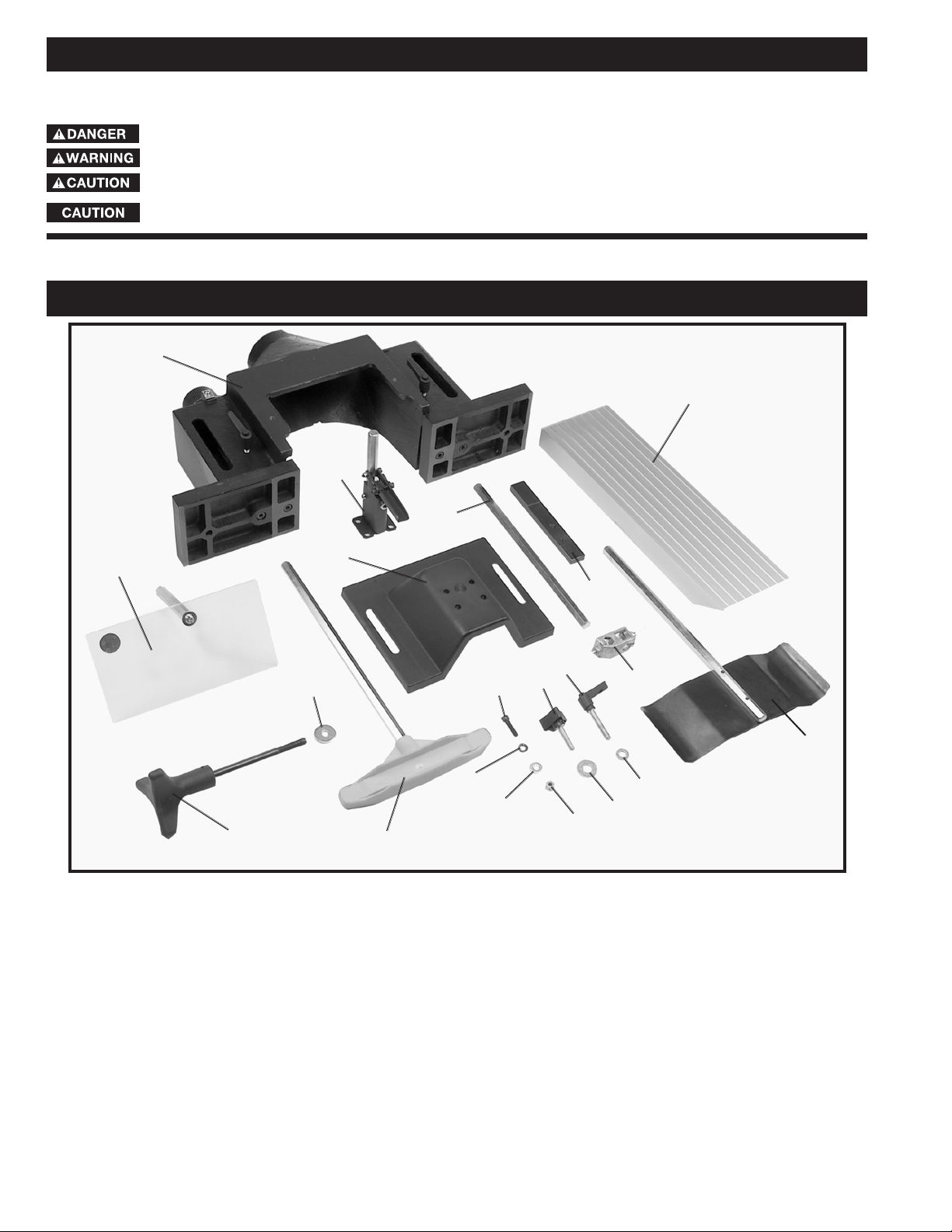
MODEL 43-812 CARTON CONTENTS
Fig. 2
1
2
17
18
20
5
4
3
14
13
12
11
10
19
16
15
9
8
7
6
1. Fence Body
2. Left and Right fence halves (2)
3. Clear Plastic Guard
4. Guard Mounting Bracket
5. Top Cover
6. Rod for fence guard
7. Lock Bars (2) for fence halves
8. Fence Locking Handles (2) for mounting fence
to shaper
9. 1/2" Flat Washers (2) for fence locking handles
10. Holddown for fence guard
11. 1/4-20x1" Hex Soc. Hd. Screw (4) for mounting
guard mounting bracket to top cover
12. 1/4" Lock Washers for mounting guard mounting
bracket to top cover (4)
13. 1/4" Flat Washers for mounting guard mounting
bracket to top cover (4)
14. 1/4-20 Hex Nuts (4) for mounting guard mounting
bracket to top cover
15. Lock Knobs (2) for mounting top cover to
fence body
16. 1/2" Flat washers (2) for mounting top cover to
fence body
17. Locking Levers for fence halves (2)
18. 11/32" Flat Washers for locking levers (2)
19. Brackets for fence guard (4)
20. Spring clamp for fence guard
* 5/32" T-handle allen wrench (* not shown)
Page 3
3
MODEL 43-812X CARTON CONTENTS
1. Fence Body
2. Left and Right fence halves (2)
3. Clear Plastic Guard
4. Guard Mounting Bracket
5. Top Cover
6. Rod for fence guard
7. Lock Bars (2) for fence halves
8. Fence Locking Handles (2) for mounting fence
to shaper
9. 1/2" Flat Washers (2) for fence locking handles
10. Holddown for fence guard
11. 1/4-20x1" Hex Soc. Hd. Screw (4) for mounting
guard mounting bracket to top cover
12. 1/4" Lock Washers for mounting guard mounting
bracket to top cover (4)
13. 1/4" Flat Washers for mounting guard mounting
bracket to top cover (4)
14. 1/4-20 Hex Nuts (4) for mounting guard mounting
bracket to top cover
15. Lock Knobs (2) for mounting top cover to
fence body
16. 1/2" Flat washers (2) for mounting top cover to
fence body
17. Locking Levers for fence halves (2)
18. 11/32" Flat Washers for locking levers (2)
19. Brackets for fence guard (4)
20. Spring clamp for fence guard
21. 1/4-20x1½" Pan Head Screw (2) for fence lock knob
22. Spring (2) for fence lock knob
23. Fence Lock Knob (2)
* 5/32" T-handle allen wrench (* not shown)
Fig. 2A
1
2
3
4
5
6
7
8
9
10
11
12
13
14
15
16
17
18
19
20
21
22
23
Page 4
4
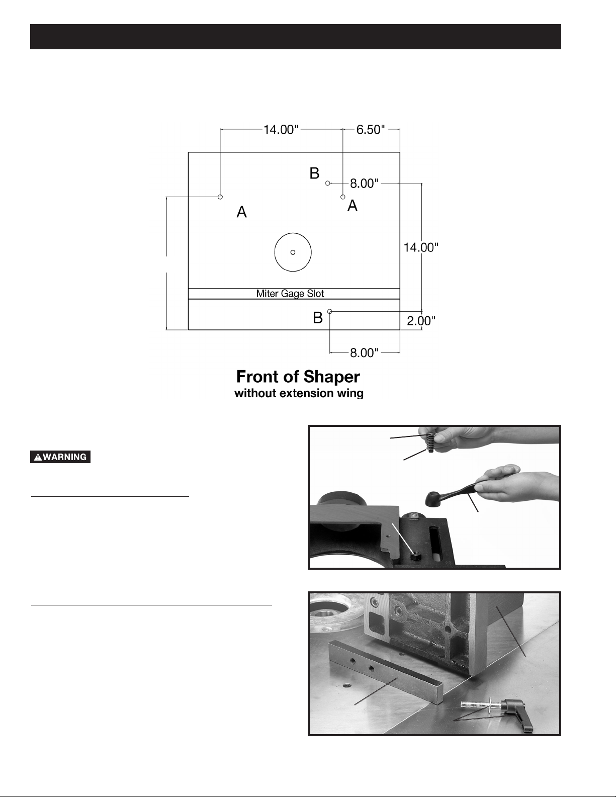
If you are assembling this fence to an early model Heavy Duty Shaper, the table will need to have four holes drilled and
tapped to accept the fence locking handles. The four holes are indicated at (A) and (B) Fig. 3. Using measurements
from Fig. 3, mark and drill the top of the shaper table in the desired locations using a 21/64" diameter drill bit, then tap
the four holes using a 3/8"-24 tap (not supplied). NOTE: Two holes (A) Fig. 3, will permit the fence to be mounted
parallel to the miter gage slot, and two holes (B) will permit the fence to be mounted 90 degrees to the miter gage slot.
Fig. 3
FENCE TO SHAPER TABLE
DISCONNECT MACHINE FROM
POWER SOURCE.
FOR MODEL 43-812X ONLY
1. Place the fence lock knob (A) Fig. 3A, on the hex
head screw (B). Place spring (C) on 1/4-20x1½" pan
head screw (D). Insert screw (D) through the hole in the
fence lock knob (A) and thread into the hex head screw
(B) and tighten securely. Repeat this process for the
remaining fence lock knob.
FOR BOTH MODELS 43-812 AND 43-812X
2. Place fence body (C) Fig. 4, on the table as shown,
and locate the two fence locking levers with 11/32"
washers (D) and fence lock bars (E).
Fig. 4
C
D
E
15.75"
ASSEMBLY
Fig. 3A
A
B
C
D
Page 5

5
Fig. 5
Fig. 6
Fig. 7
Fig. 9
Fig. 8
4. Locate the two fence locking handles and 1/2"
washers, one of which is shown at (F) Fig. 7, and fasten
fence body (C) through the slot in fence body to one of
the set of holes located on the shaper table illustrated in
Fig. 3.
5. Figure 8, illustrates fence body (C) fastened to the
table with the two fence locking handles (F).
6. Loosen locking lever (D) Fig. 9, and slide rear of
fence half (G) onto locking bar (E). Assemble remaining
fence half in the same manner. Then tighten locking
lever (D).
3. Fasten bar (E) to the front of the fence half using
the locking lever and 11/32" flat washers (D), as shown
in Figs. 5 and 6. Assemble the remaining bar to the other
fence half in the same manner. NOTE: Locking levers
(D) are spring-loaded and can be repositioned by
pulling out the handle and repositioning it on the nut
located underneath the hub of the handle.
D
E
E
D
F
C
F
C
G
E
D
Page 6

6
Fig. 10
Fig. 11
Fig. 13
Fig. 14
7. Align the four holes in the bottom of the guard
mounting bracket (H) Fig. 10 with the four holes in the
top of the top cover (J). Place a 1/4" lockwasher onto a
1/4-20x1" screw. Insert the screw through the hole in the
guard mounting bracket (H) and the top cover (J). Place
a 1/4" flat washer onto the screw and thread a 1/4-20
hex nut onto the screw and tighten securely. Repeat this
process for the three remaining holes in the guard
mounting bracket and the top cover.
8. Assemble top cover (J) Fig. 11, to top of fence body
(C) using the two locking knobs (K) and 1/2" flat washers
(L).
9. Fig. 12, illustrates top cover (J) properly assembled
to the fence body.
GUARDS TO FENCE BODY
1. Assemble guard bracket (A) Fig. 13, and hex rod (B)
to upright hex shaft (C) as shown.
2. Assemble two guard brackets (A) Fig. 14, and clear
plastic guard (D) to holddown (E) as shown.
H
J
M
N
O
P
J
C
K
L
Fig. 12
B
C
A
D
E
A
L
K
L
K
J
Page 7

7
Fig. 15
Fig. 16
Fig. 17
Fig. 18
3. Assemble holddown/clear plastic guard assembly to
hex rod (B) as shown in Fig. 15.
4. Assemble guard bracket (A) Fig. 16, and spring
clamp (F) to hex rod (B) as shown, then tighten all set
screws.
5. The spring guard (F), holddown (E), and clear plastic
guard (D) can be flipped up out of the way as shown
in Fig. 17, by lifting up on locking lever (G), when not in
use or when making adjustments. CAUTION: When the
guard assembly is in the down position as shown in
Fig. 16, make certain locking lever (G) is in the locked
position as shown.
6. Fig. 18, illustrates complete fence and guard
assembly mounted 90 degrees to miter gage slot.
B
B
A
G
F
F
E
D
G
Page 8

8
FENCE CONTROLS
AND ADJUSTMENTS
1. The fence halves (A) Fig. 19, should
be adjusted endwise so the opening at the spindle is
never more than is required to clear the cutter.
2. To adjust the fence halves (A) Fig. 19 endwise, loosen
the two fence locking levers (B), slide the fence halves to
the required positions, and tighten locking levers (B).
3. Each fence half (A) Fig. 19, can be moved
independently, in or out, depending on the type of
shaping operation that is being performed. To move the
fence halves in or out, loosen one of the lock knobs (C)
and turn one of the adjusting knobs (D), depending on
which fence half is being moved. Turn knob (D) until the
correct setting is obtained and tighten lock knob (C).
4. The complete fence assembly can be rapidly
positioned on the table by loosening two clamp handles
(E) Fig. 19, moving the fence assembly to the desired
position and tightening the two clamp handles (E).
5. Indicator pointers (F) Fig. 20, are supplied to give the
exact dimension each fence half is moved.
Make sure that the pointer does not rub
against the adjusting knobs, if the pointer does rub
against the adjustment knob the pointer will have to
be adjusted. Loosen the round head screw (G) Fig.
20, that holds the pointer to the fence assembly and
pull the pointer out until it does not come in contact
with the adjusting knob and then retighten the round
head screw.
Fig. 19
Fig. 20
OPERATING CONTROLS AND ADJUSTMENTS
Fig. 21
Fig. 22
6. Using a straight edge (G) Fig. 21, check to see if the two fence halves (H) are parallel to each
other. If parallelism cannot be achieved by adjusting one of the two fence halves (H) in or out,
shims (J) Fig. 22 (not supplied), can be placed between the fence mount (K) and the ram (M),
which is bolted to fence mount (K).
A
A
B
B
C
C
E
E
D
D
F
G
H
G
K
M
J
Page 9

9
Fig. 23
Fig. 24 Fig. 25
GUARD CONTROLS AND ADJUSTMENTS
DISCONNECT MACHINE FROM POWER SOURCE.
The spring clamp (A) Fig. 23, holddown (B), and clear plastic guard (C) are fully adjustable to
provide safe protection for most applications. NOTE: For certain applications, the spindle guard
supplied with the shaper may have to be used or a custom guard may need to be fabricated.
1. Using a square (not shown), check to see if shaft (D) Fig. 23, on spring clamp (A) is 90 degrees
to the table surface. If an adjustment is necessary, proceed as follows:
Lift up on guard locking handle (E) Fig. 24, loosen lock nut (F), and turn screw (G) until shaft (D)
Fig. 23, is 90 degrees to the table surface. Then tighten lock nut (F) Fig. 24.
Push down on guard locking handle (E) Figs. 24 and 25, until it locks in place as shown in Fig.
25. If the locking action is too loose or tight, loosen screw (H) Fig. 25, and adjust cam washer (J),
then tighten screw (H). Repeat this adjustment on the screw and cam washer located on the other
side of guard locking handle (E).
C
A
D
B
E
F
G
E
H
J
Page 10

10
4. Loosen set screws on guard mounting bracket (P) Fig. 27, and adjust spring clamp (N) so it will provide
inward pressure on workpiece, then tighten set screws. NOTE: Set screws on guard mounting bracket (R)
Fig. 27, can be loosened to provide additional extension of guard assembly.
TURN THE CUTTER BY HAND TO MAKE CERTAIN CUTTER DOES NOT CONTACT ANY
OF THE GUARDING OR FENCE HALVES BEFORE CONNECTING THE SHAPER TO
POWER SOURCE.
Always make certain guard locking handle (E) Fig. 27, is in the locked position as shown
and all set screws on guarding assembly are tight before turning shaper on.
Fig. 26
2. Adjust holddown (B) Fig. 26, by placing a piece of material which will be used on the table as shown.
Loosen set screws on guard mounting bracket (K) and adjust holddown (B) over top of workpiece to provide
some downward pressure and tighten set screws.
3. Adjust clear plastic guard (L) Fig. 26, by loosening set screws on guard mounting bracket (M) and
locating the guard so it will deflect the wood chips and provide protection from reaching the cutter, then
retighten set screws.
Fig. 27
K
L
M
B
P
E
R
N
Page 11

11
PARTS, SERVICE OR WARRANTY ASSISTANCE
All Delta Machines and accessories are manufactured to high quality standards and are serviced by a network
of Porter-Cable • Delta Factory Service Centers and Delta Authorized Service Stations. To obtain additional
information regarding your Delta quality product or to obtain parts, service, warranty assistance, or the location
of the nearest service outlet, please call 1-800-223-7278 (In Canada call 1-800-463-3582).
A complete line of accessories is available from your Delta Supplier, Porter-Cable • Delta Factory Service Centers,
and Delta Authorized Service Stations. Please visit our Web Site
www.deltamachinery.com for a catalog or
for the name of your nearest supplier.
Since accessories other than those offered by Delta have not been tested with this
product, use of such accessories could be hazardous. For
safest operation, only Delta
recommended accessories should be used with this product.
ACCESSORIES
Two Year Limited New Product Warranty
Delta will repair or replace, at its expense and at its option, any new Delta machine, machine part, or machine accessory
which in normal use has proven to be defective in workmanship or material, provided that the customer returns the product
prepaid to a Delta factory service center or authorized service station with proof of purchase of the product within two
years and provides Delta with reasonable opportunity to verify the alleged defect by inspection. For all refurbished Delta
product, the warranty period is 180 days. Delta may require that electric motors be returned prepaid to a motor
manufacturer’s authorized station for inspection and repair or replacement. Delta will not be responsible for any asserted
defect which has resulted from normal wear, misuse, abuse or repair or alteration made or specifically authorized by
anyone other than an authorized Delta service facility or representative. Under no circumstances will Delta be liable for
incidental or consequential damages resulting from defective products. This warranty is Delta’s sole warranty and sets
forth the customer’s exclusive remedy, with respect to defective products; all other warranties, express or implied, whether
of merchantability, fitness for purpose, or otherwise, are expressly disclaimed by Delta.
Page 12

The following are trademarks of PORTER-CABLE·DELTA (Las siguientes son marcas registradas de PORTER-CABLE S.A.): Auto-Set®,
BAMMER®, B.O.S.S.®, Builder’s Saw®, Contractor’s Saw®, Contractor’s Saw II™, Delta®, DELTACRAFT®, DELTAGRAM™, Delta Series
2000™, DURATRONIC™, Emc²™, FLEX®, Flying Chips™, FRAME SAW®, Homecraft®, INNOVATION THAT WORKS®, Jet-Lock®,
JETSTREAM®, ‘kickstand®, LASERLOC®, MICRO-SET®, Micro-Set®, MIDI LATHE®, MORTEN™, NETWORK™, OMNIJIG®, POCKET
CUTTER®, PORTA-BAND®, PORTA-PLANE®, PORTER-CABLE®&(design), PORTER-CABLE®PROFESSIONAL POWER TOOLS, Posi-Matic®,
Q-3®&(design), QUICKSAND®&(design), QUICKSET™, QUICKSET II®, QUICKSET PLUS™, RIPTIDE™&(design), SAFE GUARD II®, SAFELOC®, Sanding Center®, SANDTRAP®&(design), SAW BOSS®, Sawbuck™, Sidekick®, SPEED-BLOC®, SPEEDMATIC®, SPEEDTRONIC®,
STAIR EASE®, The American Woodshop®&(design), The Lumber Company®&(design), THE PROFESSIONAL EDGE®, THE PROFESSIONAL
SELECT®, THIN-LINE™, TIGER®, TIGER CUB®, TIGER SAW®, TORQBUSTER®, TORQ-BUSTER®, TRU-MATCH™, TWIN-LITE®,
UNIGUARD®, Unifence®, UNIFEEDER™, Unihead®, Uniplane™, Unirip®, Unisaw®, Univise®, Versa-Feeder®, VERSA-PLANE®, WHISPER
SERIES®, WOODWORKER’S CHOICE™.
Trademarks noted with ™ and ® are registered in the United States Patent and Trademark Office and may also be registered in other
countries. Las Marcas Registradas con el signo de ™ y ® son registradas por la Oficina de Registros y Patentes de los Estados Unidos y
también pueden estar registradas en otros países.
PORTER-CABLE • DELTA SERVICE CENTERS
(CENTROS DE SERVICIO DE PORTER-CABLE
• DELTA)
Parts and Repair Service for Porter-Cable •Delta Machinery are Available at These Locations
(Obtenga Refaccion de Partes o Servicio para su Herramienta en los Siguientes Centros de Porter-Cable
•
Delta)
Authorized Service Stations are located in many large cities. Telephone 800-438-2486 or 731-541-6042 for assistance locating one.
Parts and accessories for Porter-Cable
·
Delta products should be obtained by contacting any Porter-Cable·Delta Distributor, Authorized
Service Center, or Porter-Cable
·
Delta Factory Service Center. If you do not have access to any of these, call 800-223-7278 and you will
be directed to the nearest Porter-Cable
·
Delta Factory Service Center. Las Estaciones de Servicio Autorizadas están ubicadas en muchas
grandes ciudades. Llame al 800-438-2486 ó al 731-541-6042 para obtener asistencia a fin de localizar una. Las piezas y los accesorios
para los productos Porter-Cable
·
Delta deben obtenerse poniéndose en contacto con cualquier distribuidor Porter-Cable·Delta, Centro
de Servicio Autorizado o Centro de Servicio de Fábrica Porter-Cable
·
Delta. Si no tiene acceso a ninguna de estas opciones, llame al
800-223-7278 y le dirigirán al Centro de Servicio de Fábrica Porter-Cable
·
Delta más cercano.
ARIZONA
Tempe 85282 (Phoenix)
2400 West Southern Avenue
Suite 105
Phone: (602) 437-1200
Fax: (602) 437-2200
CALIFORNIA
Ontario 91761 (Los Angeles)
3949A East Guasti Road
Phone: (909) 390-5555
Fax: (909) 390-5554
San Leandro 94577 (Oakland)
3039 Teagarden Street
Phone: (510) 357-9762
Fax: (510) 357-7939
COLORADO
Arvada 80003 (Denver)
8175 Sheridan Blvd., Unit S
Phone: (303) 487-1809
Fax: (303) 487-1868
FLORIDA
Davie 33314 (Miami)
4343 South State Rd. 7 (441)
Unit #107
Phone: (954) 321-6635
Fax: (954) 321-6638
Tampa 33609
4538 W. Kennedy Boulevard
Phone: (813) 877-9585
Fax: (813) 289-7948
GEORGIA
Forest Park 30297 (Atlanta)
5442 Frontage Road,
Suite 112
Phone: (404) 608-0006
Fax: (404) 608-1123
ILLINOIS
Addison 60101 (Chicago)
400 South Rohlwing Rd.
Phone: (630) 424-8805
Fax: (630) 424-8895
Woodridge 60517 (Chicago)
2033 West 75th Street
Phone: (630) 910-9200
Fax: (630) 910-0360
MARYLAND
Elkridge 21075 (Baltimore)
7397-102 Washington Blvd.
Phone: (410) 799-9394
Fax: (410) 799-9398
MASSACHUSETTS
Braintree 02185 (Boston)
719 Granite Street
Phone: (781) 848-9810
Fax: (781) 848-6759
Franklin 02038 (Boston)
Franklin Industrial Park
101E Constitution Blvd.
Phone: (508) 520-8802
Fax: (508) 528-8089
MICHIGAN
Madison Heights 48071 (Detroit)
30475 Stephenson Highway
Phone: (248) 597-5000
Fax: (248) 597-5004
MINNESOTA
Minneapolis 55429
5522 Lakeland Avenue North
Phone: (763) 561-9080
Fax: (763) 561-0653
MISSOURI
North Kansas City 64116
1141 Swift Avenue
Phone: (816) 221-2070
Fax: (816) 221-2897
St. Louis 63119
7574 Watson Road
Phone: (314) 968-8950
Fax: (314) 968-2790
NEW YORK
Flushing 11365-1595 (N.Y.C.)
175-25 Horace Harding Expwy.
Phone: (718) 225-2040
Fax: (718) 423-9619
NORTH CAROLINA
Charlotte 28270
9129 Monroe Road, Suite 115
Phone: (704) 841-1176
Fax: (704) 708-4625
OHIO
Columbus 43214
4560 Indianola Avenue
Phone: (614) 263-0929
Fax: (614) 263-1238
Cleveland 44125
8001 Sweet Valley Drive
Unit #19
Phone: (216) 447-9030
Fax: (216) 447-3097
OREGON
Portland 97230
4916 NE 122 nd Ave.
Phone: (503) 252-0107
Fax: (503) 252-2123
PENNSYLVANIA
Willow Grove 19090
520 North York Road
Phone: (215) 658-1430
Fax: (215) 658-1433
TEXAS
Carrollton 75006 (Dallas)
1300 Interstate 35 N, Suite 112
Phone: (972) 446-2996
Fax: (972) 446-8157
Houston 77055
West 10 Business Center
1008 Wirt Road, Suite 120
Phone: (713) 682-0334
Fax: (713) 682-4867
WASHINGTON
Auburn 98001(Seattle)
3320 West Valley HWY, North
Building D, Suite 111
Phone: (253) 333-8353
Fax: (253) 333-9613
CANADIAN PORTER-CABLE • DELTA SERVICE CENTERS
ALBERTA
Bay 6, 2520-23rd St. N.E.
Calgary, Alberta
T2E 8L2
Phone: (403) 735-6166
Fax: (403) 735-6144
BRITISH COLUMBIA
8520 Baxter Place
Burnaby, B.C.
V5A 4T8
Phone: (604) 420-0102
Fax: (604) 420-3522
MANITOBA
1699 Dublin Avenue
Winnipeg, Manitoba
R3H 0H2
Phone: (204) 633-9259
Fax: (204) 632-1976
ONTARIO
505 Southgate Drive
Guelph, Ontario
N1H 6M7
Phone: (519) 836-2840
Fax: (519) 767-4131
QUÉBEC
1515 ave.
St-Jean Baptiste,
Québec, Québec
G2E 5E2
Phone: (418) 877-7112
Fax: (418) 877-7123
1447, Begin
St-Laurent, (Montréal),
Québec
H4R 1V8
Phone: (514) 336-8772
Fax: (514) 336-3505
 Loading...