

Page 1

-
Z
20"
Variable
Speed
tJ)
;a
Scroll
Saw
c:
-I
with
Quickset
Blade
Changing
Feature
o
(Model
40-640)
-
-I
z
3:
»
z
c:
»
r-
DATED
8-15-91
PART
NO.
1344248
@Delta Inlernational
Machinery
Corp.
1991
.·.CELTA
Page 2
TABLE OF CONTENTS
SAFETY RULES 3
ADDITIONAL SAFETY RULES FOR SCROLL SAWS 4
UNPACKING AND CLEANING 5
ASSEMBLY INSTRUCTIONS 5
FASTENING SCROLL SAW
TO
SUPPORTING SURFACE 6
CONNECTING SCROLL SAW
TO
POWER SOURCE
Power
Connections
7
Grounding
Instructions
7
OPERATING CONTROLS AND ADJUSTMENTS
On-Off
Switch
8
Speed
Control
8
Locking
Switch
In
The
"OFF"
Position
8
Changing
Blades
8
Table
Insert
9
Blade Breakage 9
Adjusting
Blade Tension "
10
Tilting
The
Table
10
Leveling
The
Table
11
Adjusting
Holddown
11
Adjusting
Dust
Blower
11
Tool
Holder
12
OPERATION
Following A Line
12
Inside
Cutting
13
MAINTENANCE
Lubrication
14
Brush
Inspection
And
Replacement
15
Replacing
Fuse
15
PARTS, SERVICE OR WARRANTY ASSISTANCE
17
AUTHORIZED SERVICE STATIONS
18
WARRANTY 20
2
Page 3

-=====
SAFETY RULES
As with all machinery there are certain hazards involved with operation and use of the machine. Using the machine
with respect and caution will considerably lessen the possibility of personal injury. However, if normal safety precautions
are overlooked or ignored, personal injury to the operator
may
result.
This
machine
was designed for certain applications only. Delta Machinery strongly recommends that this machine NOT
be modified and/or used for any application other than for which it was designed. If you have any questions relative
to its application DO NOT use the
machine
until you have written Delta Machinery and we have advised you
DELTA
INTERNATIONAL
MACHINERY CORP.
MANAGER
OF TECHNICAL SERVICES
246
ALPHA
DRIVE
PITTSBURGH,
PENNSYLVANIA
15238
(IN
CANADA:
644
IMPERIAL
ROAD, GUELPH,
ONTARIO
N1H 6M7)
WARNING: FAILURE TO FOLLOW THESE RULES
MAY RESULT
IN
SERIOUS PERSONAL INJURY
1. FOR YOUR OWN
SAFETY,
READ
INSTRUCTION
15.
DON'T
OVERREACH. Keep proper footing and
MANUAL
BEFORE
OPERATING
THE
TOOL.
Learn the balance at all times.
tool's application and limitations as well as the specific
16.
MAINTAIN
TOOLS
IN
TOP CONDITION. Keep tools
hazards peculiar to it.
sharp and clean for best and safest performance. Follow
2. KEEP
GUARDS
IN
PLACE
and
in
working order.
instructions for lubricating and changing accessories.
3.
ALWAYS
WEAR
EYE
PROTECTION.
17.
DISCONNECT
TOOLS
before servicing and when
changing accessories such as blades, bits, CUllers,
4. GROUND
ALL
TOOLS.
If tool is equipped with three-
prong plug, it should be plugged into a three-hole elec-
etc.
trical receptacle. If an adapter is used to
accommodate
18. USE RECOMMENDED ACCESSORIES. The use of
a two-prong receptacle, the adapter lug must be attach-
improper accessories may cause hazards.
ed to a known ground. Never remove the third prong.
19. AVOID ACCIDENTAL STARTING. Make sure switch
5. REMOVE
ADJUSTING
KEYS
AND
WRENCHES.
is in
"OFF"
position before plugging
in
power cord.
Form habit of checking to see that keys and adjusting
20. NEVER
STAND
ON
TOOL.
Serious injury could
wrenches are removed from tool before turning it
"on."
occur
if the tool is tipped or if the CUlling tool is accident-
6. KEEP
WORK
AREA
CLEAN.
Cluttered areas and ally contacted.
benches invite accidents.
21. CHECK
DAMAGED
PARTS. Before further use of the
7.
DON'T
USE
IN
DANGEROUS ENVIRONMENT. Don't
tool, a guard or other part that
is
damaged
should be
use power tools in
damp
or wet locations, or expose them
carefully checked to ensure that it will operate properly
to rain. Keep work area well-lighted.
and perform its intended function - check for alignment
of moving parts, binding of moving parts, breakage of
8. KEEP CHILDREN
AND
VISITORS
AWAY.
All children
parts, mounting, and any other conditions that may affect
and visitors should be kept a safe distance from work area.
its operation. A guard or other part that
is
damaged should
9.
MAKE
WORKSHOP
CHILDPROOF
- with padlocks,
be properly repaired or replaced.
master switches, or by removing starter keys.
22.
DIRECTION OF FEED. Feed work into a blade or
10.
DON'T
FORCE
TOOL.
It will do the job
beller
and
culler against the direction of rotation of the blade or culler
be safer at the rate for which it was designed.
only.
11. USE RIGHT
TOOL.
Don't
force tool or
allachment
23. NEVER
LEAVE
TOOL
RUNNING
UNATTENDED.
to do a job for which it was not designed.
TURN
POWER
OFF.
Don't
leave tool until it comes to a
complete stop.
12.
WEAR
PROPER
APPAREl.
No loose clothing,
gloves, neckties, rings, bracelets, or other jewelry to get
24. DRUGS,
ALCOHOL,
MEDICATION.
Do not operate
caught
in
moving parts. Nonslip foot wear
is
recommend-
tool while under the influence of drug, alcohol or any
ed. Wear protective hair covering
to
contain long hair.
medication.
13.
ALWAYS
USE
SAFETY
GLASSES.
Wear safety
25.
MAKE
SURE
TOOL
IS DISCONNECTED FROM
glasses (must
comply
with ANSI Z87.1). Everyday eye-
POWER
SUPPLY
while motor
is
being mounted, con-
glasses only have impact resistant lenses; they are not
nected or reconnected.
safety glasses. Also use face or dust mask
if
CUlling opera-
26. WARNING: The dust generated by certain woods and
tion is dusty.
wood
products
can be injurious to your health. Always
14. SECURE
WORK.
Use
clamps
or a vise to hold work
operate machinery
in
well ventilated areas and provide
when practical.
It's
safer than using your hand and frees
for proper dust removal. Use wood dust collection systems
both hands to operate tool.
whenever possible.
3
Page 4

ADDITIONAL SAFETY RULES FOR SCROLL SAWS
1. WARNING: Do not operate your scroll saw until it is
completely assembled and installed according to the
instructions.
2. IF YOU ARE NOT thoroughly familiar with the operation of scroll saws, obtqin advice from your supervisor,
instructor or other qualified person.
3. YOUR SCROLL
SAW
MUST be securely fastened
to
a stand or workbench. If there
is
any tendency for the
stand or workbench
to
move during operation, the stand
or workbench MUST be fastened
to
the floor.
4. THIS SCROLL
SAW
is intended for indoor use only.
5. MAKE SURE blade
is
properly tensioned before
operating saw.
6. TO AVOID blade breakage
ALWAYS
adjust blade
tension correctly.
7. MAKE SURE the blade teeth point downward toward
the table.
8. NEVER turn the saw
"ON"
before clearing the table
of all objects (tools, scraps of wood, etc.).
9.
DO
NOT cut material that is too small to
be
safely
supported.
10. AVOID awkward hand positions where a sudden slip
could cause a hand to move into the blade.
11.
ALWAYS
keep hands and fingers away from the
blade.
12.
ALWAYS
adjust holddown foot for each new
operation.
13. DO NOT USE dull or bent blades.
14. DO NOT attempt
to
saw material that does not have
a flat surface, unless a suitable support is used.
15.
MAKE
"relief"
cuts before cutting long curves.
16. NEVER attempt to cut a curve that is too tight for
the blade being used.
17. WHEN backing a blade out of a workpiece, the blade
may bind in the saw kerf. This is usually caused by
sawdust
in
the kerf. If this happens, turn
"OFF"
the switch
and remove plug from power source outlet. Wedge open
the kerf and back blade out of the workpiece.
4
18.
ALWAYS
hold the work firmly against the table.
19. DO NOT feed the material too fast while cutting.
Only feed the material fast enough so that the blade will
cut.
20. NEVER start the Scroll Saw with the stock pressed
against the blade.
21. WHEN cutting a large workpiece
MAKE
SURE the
material is supported at table height.
22. USE CAUTION when cutting material which
is
ir-
regular
in
cross section, which could pinch the blade
before the cut is completed. A piece of moulding, for
example, must lay flat on the table and not be permitted
to
rock while being cut.
23. USE CAUTION when cutting round material such
as
dowel rods or tubing. They have a tendency
to
roll while
being cut, causing the blade to
"bite."
Use a V-block to
control the piece.
24.
ALWAYS
release blade tension before loosening the
blade holder screw.
25. MAKE CERTAIN table tilting lock
is
tightened before
starting the machine.
26. NEVER reach under the table while the machine is
running.
27. NEVER perform layout, assembly or set-up work on
the table while the saw
is
operating.
28.
ALWAYS
STOP the saw before removing scrap
pieces from the table.
29. SHOULD any part of your scroll saw be missing,
damaged, or fail
in
any way, or any electrical component
fail
to
perform properly, shut off switch and remove plug
from power supply outlet. Replace missing, damaged or
failed parts before resuming operation.
30.
ADDITIONAL
INFORMATION regarding the safe
and proper operation of this product is available from the
National Safety Council, 444
N.
Michigan Avenue,
Chicago, IL 60611,
in
the Accident Prevention Manual for
Industrial Operations and also in the Safety Data Sheets
provided by the NSC. Please also refer
to
the American
National Standards Institute ANSI 01.0 Safety Requirements for Woodworking Machinery and the U.S. Depart-
ment of Labor OSHA 1910.213 Regulations.
Page 5
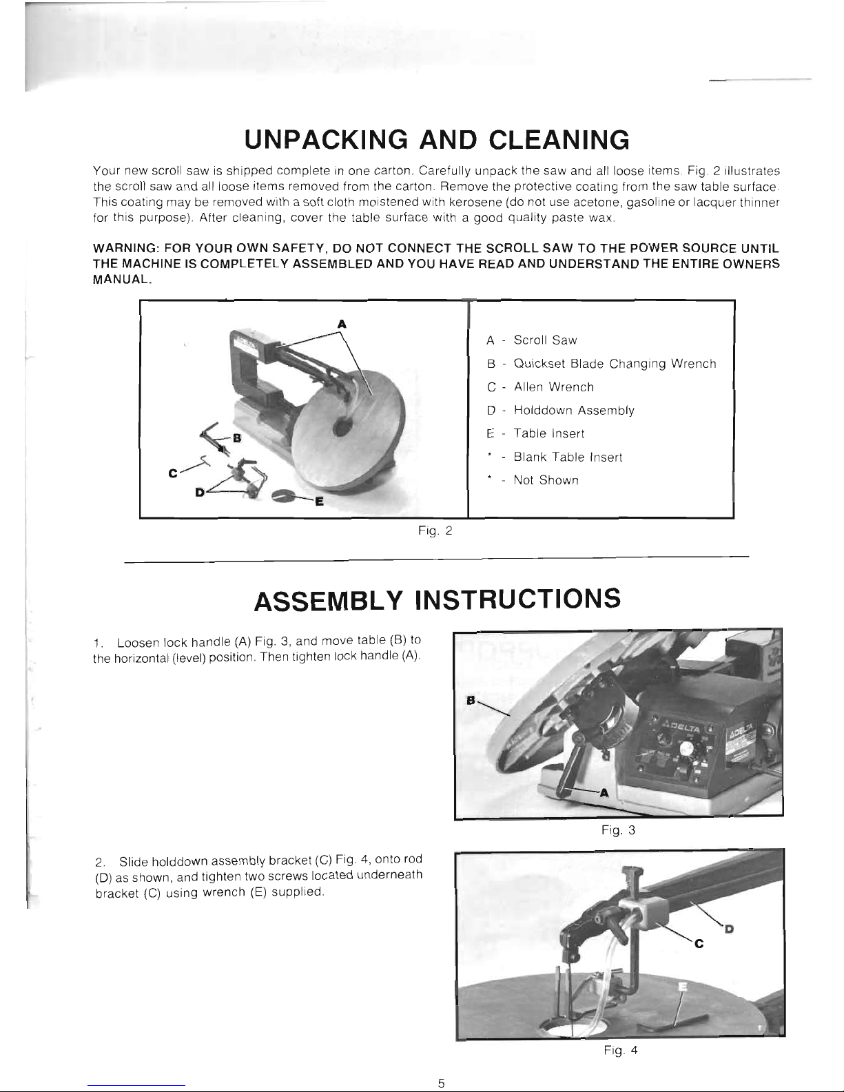
UNPACKING AND CLEANING
Your
new scroll saw is
shipped
complete
in
one
carton. Carefully
unpack
the
saw
and all loose items. Fig. 2 Illustrates
the scroll saw and all loose items removed from the carton
Remove
the
protective
coating from the saw table surface.
This coating
may
be removed with a soft cloth moistened with kerosene (do not use acetone,
gasoline
or
lacquer thinner
for this purpose). After cleaning,
cover
the table
surface
with a
good
quality
paste wax.
WARNING: FOR
YOUR
OWN
SAFETY,
DO
NOT
CONNECT
THE
SCROLL
SAW
TO
THE
POWER
SOURCE
UNTIL
THE MACHINE IS
COMPLETELY
ASSEMBLED
AND
YOU
HAVE READ AND
UNDERSTAND
THE
ENTIRE
OWNERS
MANUAL.
A
A Scroll
Saw
B -
Quickset
Blade
Changing
Wrench
C - Allen
Wrench
o -
Holddown
Assembly
E
Table
Insert
Blank
Table
Insert
Not
Shown
Fig. 2
ASSEMBLY INSTRUCTIONS
1.
Loosen
lock
handle
(A) Fig. 3, and
move
table (B) to
the horizontal (level) position. Then tighten lock handle (A).
Fig. 3
2.
Slide holddown assembly bracket
(C)
Fig. 4, onto rod
(D) as shown, and tighten two screws located
underneath
bracket
(C)
using
wrench
(E) supplied.
Fig. 4
5
Page 6

3.
Connect air hose
(F)
Fig.
5,
to end of blower tube (G)
as shown.
Fig. 5
4. Assemble table insert (H) Fig.
6,
to opening in table,
as shown.
Fig. 6
FASTENING SCROLL SAW
TO SUPPORTING SURFACE
Your scroll saw MUST be securely fastened to a stand or workbench using the three mounting holes in the base of
the saw, two of which are shown at (A) Fig.
7.
IMPORTANT: If there is any tendency for the stand or workbench to move during operation, the stand or workbench
must be fastened to the floor.
Fig. 7
6
Page 7

CONNECTING SCROLL SAW TO POWER SOURCE
POWER CONNECTIONS
A separate electrical circuit should be used for your tools. This circuit should not be less than
#12 wire and should be protected with a 20
Amp
time lag fuse. If an extension cord is used, use
only 3-wire extension cords which have 3-prong grounding type plugs and 3-pole receptacles which
accept the tools plug. For distances up to 100 feet use #12 wire. For distances up to 150 feet
use #10 wire. Have a certified electrician replace or repair damaged or worn cord immediately.
Before connecting the motor to the power line, make sure the switch
is
in the
"OFF"
position
and be sure that the electric current
is
of the same characteristics
as
stamped on motor nameplate.
All line connections should make good contact. Running on low voltage will injure the motor.
GROUNDING INSTRUCTIONS
WARNING: THIS TOOL MUST
BE
GROUNDED WHILE
IN
USE
TO PROTECT THE OPERATOR FROM ELECTRIC SHOCK.
In
the event of a malfunction or breakdown, grounding
Use only 3-wire extension cords that have 3-prong ground-
provides a path of least resistance for electric current to
ing type plugs and 3-hole receptacles that accept the tool's
reduce the risk of electric shock. This tool
is
equipped with
plug, as shown
in
Fig.
8.
an
electric cord having
an
equipment-grounding conductor
and a grounding plug. The plug must be plugged into a
Repair or replace damaged or worn cord immediately.
matching outlet that
is
properly installed and grounded
in
accordance with all local codes and ordinances.
This tool is intended for use on a circuit that has an outlet
and a plug that looks like the one shown
in
Fig.
8.
A
Do not modify the plug provided - if it will not fit the outlet,
temporary adapter, which looks like the adapter illustrated
have the proper outlet installed by a qualified electrician.
in Fig.
9,
may be used to connect this plug to a 2-pole
receptacle, as shown
in
Fig.
9,
if a properly grounded
Improper connection of the equipment-grounding conduc-
outlet is not available. The temporary adapter should be
tor can result
in
risk of electric shock. The conductor with
used only until a properly grounded outlet can be installed
insulation having
an
outer surface that
is
green with or
by a qualified electrician.
THIS ADAPTER
IS
NOT
without yellow stripes is the equipment-grounding con-
APPLICABLE
IN
CANADA. The green-colored rigid ear,
ductor. If repair or replacement of the electric cord or plug lug, and the like, extending from the adapter must be
is necessary, do not connect the equipment grounding
connected to a permanent ground, such as a properly
conductor to a live terminal.
grounded outlet box,
as
shown
in
Fig.
9.
Check with a qualified electrician or service personnel if
CAUTION:
IN
ALL CASES, MAKE CERTAIN THE RE-
the grounding instructions are not completely understood,
CEPTACLE
IN
QUESTION
IS
PROPERLY GROUNDED.
or if in doubt as to whether the tool is properly grounded.
IF YOU ARE NOT SURE HAVE A CERTIFIED ELECTRICIAN CHECK THE RECEPTACLE.
GROUNDED
OUTLET
BOX
---r'-
GROUNDED
OUTLET
BOX
----f
CURRENT
rI
;:DING
MEANS
CARRYING
PRONGS
~
""m
GROUNDING
BLADE
~
IS
LONGEST
OF
THE 3 BLADES
fl
Fig. 8
Fig. 9
7
Page 8

OPERATING CONTROLS AND ADJUSTMENTS
ON-OFF SWITCH
The switch (A) Fig. 10, is located on the front of the saw.
To turn the saw
"ON,"
pullout
switch (A) and
to
turn the
saw
"OFF"
push in switch (A).
SPEED CONTROL
Your scroll saw can be operated at speeds of 400 to 1800
strokes per minutes. The strokes per minute
is
indicated
on the nameplate and a pointer is supplied on the switch
Fig. 10
(A) Fig. 10 To increase the strokes per minute, rotate
switch
(A)
clockwise
and
to
decrease
the strokes per
minute rotate switch (A) counterclockwise.
LOCKING SWITCH
IN
THE
"OFF"
POSITION
IMPORTANT:
We suggest that when the scroll saw
is
not
in use the switch (A) Fig. 11, be locked in the
"OFF"
position using a padlock (B) as shown.
The
padlock
(B)
prevents the switch (A) from being pulled out to the
"ON"
position.
Fig.
11
CHANGING BLADES
1.
WARNING: TO AVOID INJURY FROM ACCIDENTAL
STARTING
ALWAYS
TURN
SWITCH
"OFF"
AND
REMOVE
POWER
CORD PLUG FROM
ELECTRICAL
OUTLET BEFORE REMOVING OR REPLACING BLADE.
2.
Remove table insert and release blade tension by
pulling tension lever (A) Fig. 12, forward, as shown.
3.
Insert long end of
quickset
blade
changing
wrench
(B) Fig. 12, into hole
(C)
in
upper blade holder. This will
automatically align wrench
(0)
with blade holder screw (E).
Fig. 12
4. Turn handle
(F)
Fig. 13, of
quickset
blade
changing
wrench counterclockwise to loosen blade holder screw (E)
and remove blade (G).
5.
Repeat this operation on the lower blade holder and
remove blade
6.
Insert new blade into the lower and upper blade
holders
in
the
same
manner
making certain the blade
teeth are pointing down toward the table.
7.
Apply
blade tension by
moving
tension lever (A)
Fig. 13, to the rear.
Fig. 13
8
Page 9

Fig. 14 Fig. 15
TABLE
INSERT
The
table insert (A) can be
assembled
to the
saw
table with the
opening
in the insert
pointing
to the front
of
the table, as
shown
in Fig. 14,
or
to the right of the table, as
shown
in Fig. 15.
With
the table in the level position, 90
degrees
to the blade, the insert (A)
should
be
positioned
as
shown
in Fig. 14.
This
allows for the blade to be pivoted forward
after
it is
unclamped
from
the top blade holder,
enabling
you to
quickly
insert the blade into the next hole in a pattern when
doing
inside
cutting, as you will see later in this manual.
When
tilting the table for bevel
cutting
operations, the insert (A)
should
be
positioned
as
shown
in Fig.
15.
This
allows
clearance
for the blade
when
tilting the table.
A table insert
blank
(B) Fig. 16, is
supplied
as
standard
equipment
with
your
scroll
saw
and can be used
when
cutting
very small
workpieces
to
give
added
support
to
the bottom of the
workpiece.
Simply
cut
a slot into the
blank
and replace the
standard
insert
(A)
with the
blank
(B).
The
slot
cut
into the
blank
(B) will
only
be
as
wide
as
the blade
giving
maximum
support
to the
bottom
of
the
workpiece.
Fig.
16
BLADE BREAKAGE
Blade
breakage
is
usually
caused
by
one
or
more
of
the
following:
1.
Bending
the blade
during
installation.
2.
Improper
blade tension.
3.
Improper
blade
selection
for the
work
being
cut.
4. Forcing the
work
into the blade too rapidly.
5.
Cutting too
sharp
a turn for the blade being used.
6.
Improper
blade speed.
9
Page 10

ADJUSTING BLADE TENSION
Tension
is
applied
to
the
blade
when
the
blade
tension
lever (A) is in the rear position, as
shown
in Fig. 17.
When
the
lever
(A) is
moved
forward, as
shown
in Fig. 18, blade
tension
is released.
To increase blade tension, turn knob (8) Fig. 18, clockwise
and to decrease blade tension, turn knob
(8) counterclock-
wise.
When
adjusting
blade
tension,
lever
(A)
should
be
in the forward position, as
shown
in Fig. 18.
NOTE:
It
is
necessary
to
adjust
the
blade
tension
knob (8)
only
when
the
blade
is
removed
from both
upper
and
lower
blade
holders and a
new
or
different
type of blade is
assembled
to
the
holders. It is not
necessary
to
adjust
blade
tension
when the blade is removed and replaced
in
only the
upper
blade
holder
as in
performing
inside
CUlling
operations.
Adjusting
the
blade
for
proper
tension
is
usually
accomp-
lished
by trial and error;
however, a good
method
to
use
is to
pluck
the
rear
of
the
blade,
like a guitar
string
after
the
tension
lever
(A) Fig. 18, is
moved
to
the
rear. A
high
pitched tone
of
the blade should be heard
and
this usually
indicates
proper
tension.
Finer
blades
require
more
ten-
sioning
(a
higher
pitched
sound)
while
thicker
blades
require less tension.
TILTING THE TABLE
The
table
on
your
scroll
saw
can
be
tilted
45
degrees
to
the left for bevel CUlling operations by loosening table lock
handle
(A) Fig. 19, tilt
the
table
to the
desired
angle
and
tighten
lock
handle
(A).
NOTE:
The
table
lock
handle
(A)
can be repositioned by
removing
screw
(0)
and
removing
and
repositioning
handle
(A) on the
hex
rod located
underneath
the
hub
of the
handle.
When
bevel CUlling,
the
holddown
(8)
Fig. 20, can be
adjusted
to lay flat on
the
stock
by
loosening
screw
(C)
and tilting
the
holddown
(8)
accordingly.
Then
tighten
screw
(C).
If the
workpiece
is too thick,
causing
the
stock
to
contact
the holddown arm, the complete holddown assembly
must
be
removed,
since
thick
stock
is
heavy
enough
to resist
lifting
off
the
table
during
the
blade
up
stroke.
Fig. 17
Fig. 18
Fig. 19
Fig. 20
10
Page 11

LEVELING THE TABLE
1.
Loosen table lock handle and
move
the
table all the
way
to the right.
2. Using a
square
(A) Fig. 21,
check
to see if the table
is 90
degrees
to the saw blade, as shown.
Fig.
21
3. If the table is not at 90
degrees
to the blade, adjust
the table
accordingly
making
certain
screw
(8) Fig. 22,
contacts bottom of table surface when table is 90 degrees
to the blade.
Screw
(8) can be adjusted by loosening nut
(C), thread
screw
(8) in
or
out
the desired
distance
and
tighten nut
(C).
Fig. 22
ADJUSTING HOLDDOWN
The
holddown (A) Fig. 23,
should
be adjusted so it con-
tacts the top surface of the
work
being cut by loosening
lock handle (8) and moving holddown rod
(C)
up
or down.
Then tighten lock handle
(8). NOTE:
Handle
(8) is spring
loaded and can be repositioned by pulling
out
the handle
and repositioning it on the serrated nut located underneath
the
hub
of the handle.
Fig. 23
ADJUSTING DUST BLOWER
The
dust
blower (A) Fig. 24,
may
be moved to
direct
air
to the most effective point on the cutting line by loosening
screw
(8),
adjust
nozzle (A)
accordingly
and tighten
screw
(8).
Fig. 24
11
Page 12

TOOL HOLDER
A tool holder
(A)
Fig. 25,
is
provided on the right hand side
of the saw frame and
is
used to hold the quickset blade
changing wrench (B), allen wrench
(C) and extra blades
(D),
as
shown.
Fig. 25
OPERATION
Fig. 26
FOLLOWING A LINE
Fig. 26 illustrates a typical scroll saw operation being made following the outside line on a
pattern. With your scroll saw you should be able to cut a straight or curved line with ease. Most
beginners will experience blade wandering; however, they eventually learn to control it
as
they
become more familiar with the machine. Use scrap material to practice cuts before starting
a project. This enables you to develop your own way of cutting and you will find out what you
can and cannot do with your saw. Always hold the work firmly against the table and do not
feed the workpiece too fast while cutting. Feed the workpiece only fast enough so that the blade
will cut. Scroll saws cut faster across the grain than they do with the grain. Allow for this tendency
when cutting patterns that shift rather quickly from with-the-grain cuts to cross-grain cuts. Make
"relief"
cuts before cutting long curves and never attempt to cut a curve that
is
too tight for
the blade being used.
12
Page 13

INSIDE CUTTING
Inside cutting
is
where the blade must be threaded through a hole
in
the workpiece. The Delta
20"
Scroll Saw has
the capability
of
performing this operation quickly and easily as follows:
Fig. 27
1.
Let's assume you are performing
an
inside cutting operation on a project, similar to the one shown
in
Fig. 27, that
has numerous inside cuts to be made. This can be accomplished quickly with the Delta saw.
In
Fig. 27, the operator
has just completed one of the inside cuts and must move to the next hole.
2.
Loosen lock handle (A) Fig. 28, and raise holddown bar (B). Release blade tension by moving tension lever
(C)
forward and loosen upper blade holder screw using the quickset blade changing wrench (D). Move the blade forward
and insert it into the next hole
in
the pattern, as shown. Reassemble blade back into upper blade holder and tighten
upper blade holder screw with wrench (D).
3.
Remove quickset blade changing wrench and move
tension lever
(C)
Fig. 29, to the rear,
as
shown. Lower hold-
down and you are ready to make the next inside cut.
Fig. 29
13
Page 14

MAINTENANCE
LUBRICATION
A
To keep the scroll
saw
operating
at
peak
efficiency, we
recommend that a
simple
maintenance
procedure
be
performed
after
approximately
each 20
hours
of use.
Proceed as follows:
1. MAKE CERTAIN THE MACHINE IS DISCON-
A
NECTED FROM THE POWER SOURCE.
2. Remove four screws (A) Fig. 30, and remove side
panel
(B) from the scroll saw.
Fig. 30
3.
Release blade tension by pulling tension lever (C)
Fig. 31, forward as shown.
Fig.
31
4. Lubricate
the
shafts of
the
two special screws (D)
Fig. 32, with a few drops of light
machine
oil in the areas
where
they
pass through the
connecting
link (E). NOTE:
DO NOT REMOVE SPECIAL SCREWS TO LUBRICATE.
5.
Remove two pivot bolts (F) Fig. 32.
D
Fig. 32
6.
Thoroughly
clean
grease
from shafts (G) Fig. 33, of
both pivot bolts (F) and lubricate shafts
(G) with a few
drops of light
machine
oil.
7.
Reassemble
two pivot bolts (F) Fig. 33, to machine.
8. Replace side panel removed in STEP 2 and reapply
tension to the blade.
Fig. 33
14
Page 15

BRUSH INSPECTION
AND REPLACEMENT
CAUTION: BEFORE INSPECTING THE BRUSHES,
DISCONNECT THE MACHINE FROM THE POWER
SOURCE.
Brush life varies. It
depends
on the load on the motor.
Check the brushes after the first 50 hours of use for a new
machine
or after a new set of brushes has been installed.
After the first check,
examine
them
after
about
10
hours
of
use until
such
time that
replacement
is necessary.
Fig.
34
The brush holders,
one
of
which
is shown at (A) Fig. 34,
are located on the
motor
housing opposite each other.
Fig.
35, illustrates one of the brushes removed for inspec-
tion. When the carbon (B) on either brush is worn to
3/16"
in length or if
either
spring (C) or
shunt
wire is burned or
damaged in any way, replace both brushes. If the brushes
are found serviceable after removing, reinstall them in the
same position as removed.
Fig.
35
REPLACING FUSE
If due to overloading it
becomes
necessary to replace the
fuse in your scroll saw,
DISCONNECT THE MACHINE
FROM THE POWER SOURCE
and
unscrew
and remove
the fuse
holder
(A) Fig. 36.
Fig.
36
Fig. 37, illustrates the fuse
holder
(A) and fuse (B) re-
moved.
NOTE: Use
only 3 amp
AG type fuse for replace-
ment.
Fig.
37
15
Page 16

A
AACELTA
PARTS, SERVICE OR
WARRANTY
ASSISTANCE
All
Delta Machines and accessories are manufactured to
mation regarding your Delta quality product or to obtain
high quality standards and are serviced by a network
parts, service or warranty assistance, please call or fax
of factory service centers and authorized service stations
Delta's toll-free 'hotline' number.
listed
in
your
owner's
manual. To obtain additional infor-
Delta maintains a modern, efficient Parts Distribution Center, maintaining an inventory of over 15,000
parts located in Memphis, Tennessee.
Highly qualified and experienced Customer Service Representatives are standing by to assist you
on weekdays from 8:00 A.M. to 5:00 P.M. Memphis time.
MEMPHIS, TN 38118
4290 Raines Road
Phone: (901) 363-8800
800-223-PART
FAX:
800-535-6488
17
 Loading...