

Page 1
INSTRUCTION MANUAL
Sliding Table Attachment
(Model 34-555)
PART NO. 1346924 - 09-18-03
Copyright © 2003 Delta Machinery
To learn more about DELTA MACHINERY
visit our website at: www.deltamachinery.com.
For Parts, Service, Warranty or other Assistance,
please call
1-800-223-7278 (In Canada call 1-800-463-3582).
Page 2

2
Woodworking can be dangerous if safe and proper operating procedures are not followed. As with all machinery, there
are certain hazards involved with the operation of the product. Using the machine with respect and caution will
considerably lessen the possibility of personal injury. However, if normal safety precautions are overlooked or ignored,
personal injury to the operator may result. Safety equipment such as guards, push sticks, hold-downs, featherboards,
goggles, dust masks and hearing protection can reduce your potential for injury. But even the best guard won’t make
up for poor judgment, carelessness or inattention. Always use common sense
and exercise caution in the workshop.
If a procedure feels dangerous, don’t try it. Figure out an alternative procedure that feels safer. REMEMBER: Your
personal safety is your responsibility. For additional information please visit our website www.deltamachinery.com.
This machine was designed for certain applications only. Delta Machinery strongly recommends that this
machine not be modified and/or used for any application other than that for which it was designed. If you have any
questions relative to a particular application, DO NOT use the machine until you have first contacted Delta to determine
if it can or should be performed on the product.
Technical Service Manager
Delta Machinery
4825 Highway 45 North
Indicates an imminently hazardous situation which, if not avoided, will result in death or serious injury.
Indicates a potentially hazardous situation which, if not avoided, could result in death or serious injury.
Indicates a potentially hazardous situation which, if not avoided, may result in minor or moderate injury.
Used without the safety alert symbol indicates potentially hazardous situation which, if not avoided, may
result in property damage.
This manual contains information that is important for you to know and understand. This information relates to protecting YOUR SAFETY and PREVENTING EQUIPMENT PROBLEMS. To help you recognize this information, we use the
symbols to the right. Please read the manual and pay attention to these sections.
SAFETY GUIDELINES - DEFINITIONS
SOME DUST CREATED BY POWER SANDING, SAWING, GRINDING, DRILLING, AND OTHER
CONSTRUCTION ACTIVITIES contains chemicals known to cause cancer, birth defects or other reproductive harm.
Some examples of these chemicals are:
· lead from lead-based paints,
· crystalline silica from bricks and cement and other masonry products, and
· arsenic and chromium from chemically-treated lumber.
Your risk from these exposures varies, depending on how often you do this type of work. To reduce your exposure to
these chemicals: work in a well ventilated area, and work with approved safety equipment, always wear MSHA/NIOSH
approved, properly fitting face mask or respirator when using such tools.
READ AND UNDERSTAND ALL WARNINGS AND OPERATING INSTRUCTIONS BEFORE
USING THIS EQUIPMENT. Failure to follow all instructions listed below, may result in electric shock,
fire, and/or serious personal injury or property damage.
GENERAL SAFETY RULES
IMPORTANT SAFETY INSTRUCTIONS
Page 3

3
1. FOR YOUR OWN SAFETY, READ THE INSTRUCT-
TION MANUAL BEFORE OPERATING THE
MACHINE. Learning the machine’s application,
limitations, and specific hazards will greatly
minimize the possibility of accidents and injury.
2. USE CERTIFIED SAFETY EQUIPMENT. Eye
protection equipment should comply with ANSI
Z87.1 standards, hearing equipment should
comply with ANSI S3.19 standards, and dust mask
protection should comply with MSHA/NIOSH
certified respirator standards. Splinters, air-borne
debris, and dust can cause irritation, injury, and/or
illness.
3. DRESS PROPERLY. Do not wear tie, gloves, or
loose clothing. Remove watch, rings, and other
jewelry. Roll up your sleeves. Clothing or jewelry
caught in moving parts can cause injury.
4. DO NOT USE THE MACHINE IN A DANGEROUS
ENVIRONMENT. The use of power tools in damp
or wet locations or in rain can cause shock or
electrocution. Keep your work area well-lit to
prevent tripping or placing arms, hands, and
fingers in danger.
5. MAINTAIN ALL TOOLS AND MACHINES IN PEAK
CONDITION. Keep tools sharp and clean for best and
safest performance. Follow instructions for lubricating
and changing accessories. Poorly maintained tools and
machines can further damage the tool or machine and/or
cause injury.
6. CHECK FOR DAMAGED PARTS. Before using the
machine, check for any damaged parts. Check for
alignment of moving parts, binding of moving
parts, breakage of parts, and any other conditions
that may affect its operation. A guard or any other
part that is damaged should be properly repaired
or replaced. Damaged parts can cause further
damage to the machine and/or injury.
7. KEEP THE WORK AREA CLEAN. Cluttered areas and
benches invite accidents.
8. KEEP CHILDREN AND VISITORS AWAY. Your shop is
a potentially dangerous environment. Children and visitors
can be injured.
9. REDUCE THE RISK OF UNINTENTIONAL STARTING.
Make sure that the switch is in the “OFF” position
before plugging in the power cord. In the event of
a power failure, move the switch to the “OFF”
position. An accidental start-up can cause injury.
10. USE THE GUARDS. Check to see that all guards
are in place, secured, and working correctly to
prevent injury.
11. REMOVE ADJUSTING KEYS AND WRENCHES
BEFORE STARTING THE MACHINE. Tools, scrap
pieces, and other debris can be thrown at high
speed, causing injury.
12. USE THE RIGHT MACHINE. Don’t force a
machine or an attachment to do a job for which it
was not designed. Damage to the machine and/or
injury may result.
13. USE RECOMMENDED ACCESSORIES. The use
of accessories and attachments not recommended by Delta may cause damage to the
machine or injury to the user.
14. USE THE PROPER EXTENSION CORD. Make
sure your extension cord is in good condition.
When using an extension cord, be sure to use one
heavy enough to carry the current your product will
draw. An undersized cord will cause a drop in line
voltage, resulting in loss of power and overheating.
See the Extension Cord Chart for the correct size
depending on the cord length and nameplate
ampere rating. If in doubt, use the next heavier
gauge. The smaller the gauge number, the heavier
the cord.
15. SECURE THE WORKPIECE. Use clamps or a vise to
hold the workpiece when practical. Loss of control
of a workpiece can cause injury.
16. FEED THE WORKPIECE AGAINST THE DIRECTION
OF THE ROTATION OF THE BLADE, CUTTER, OR
ABRASIVE SURFACE. Feeding it from the other
direction will cause the workpiece to be thrown out
at high speed.
17. DON’T FORCE THE WORKPIECE ON THE
MACHINE. Damage to the machine and/or injury
may result.
18. DON’T OVERREACH. Loss of balance can make
you fall into a working machine, causing injury.
19. NEVER STAND ON THE MACHINE. Injury could occur if
the tool tips, or if you accidentally contact the cutting tool.
20. NEVER LEAVE THE MACHINE RUNNING UNATTEN-
DED. TURN THE POWER OFF. Don’t leave the machine
until it comes to a complete stop. A child or visitor could
be injured.
21. TURN THE MACHINE “OFF”, AND DISCONNECT THE
MACHINE FROM THE POWER SOURCE before
installing or removing accessories, before adjusting
or changing set-ups, or when making repairs. An
accidental start-up can cause injury.
22. MAKE YOUR WORKSHOP CHILDPROOF WITH
PADLOCKS, MASTER SWITCHES, OR BY
REMOVING STARTER KEYS. The accidental
start-up of a machine by a child or visitor could
cause injury.
23. STAY ALERT, WATCH WHAT YOU ARE DOING,
AND USE COMMON SENSE. DO NOT USE THE
MACHINE WHEN YOU ARE TIRED OR UNDER
THE INFLUENCE OF DRUGS, ALCOHOL, OR
MEDICATION. A moment of inattention while
operating power tools may result in injury.
24. THE DUST GENERATED by certain woods and
wood products can be injurious to your health.
Always operate machinery in well-ventilated areas,
and provide for proper dust removal. Use wood
dust collection systems whenever possible.
FAILURE TO FOLLOW THESE RULES MAY RESULT IN SERIOUS PERSONAL INJURY.
Page 4
4
FOREWORD
Delta Model 34-555 Sliding Table Attachment is an accessory for providing support for large capacity wood-working
operations. The fence can be positioned in the front or rear of the movable table and can be positioned to make miter
cuts. The adjustable stock stop is excellent for repetitive cutting.
FUNCTIONAL DESCRIPTION
UNPACKING AND CLEANING
Carefully unpack the accessory and all loose items from the shipping container(s). Remove the protective coating from
all unpainted surfaces. This coating may be removed with a soft cloth moistened with kerosene (do not use acetone,
gasoline or lacquer thinner for this purpose). After cleaning, cover the unpainted surfaces with a good quality household
floor paste wax.
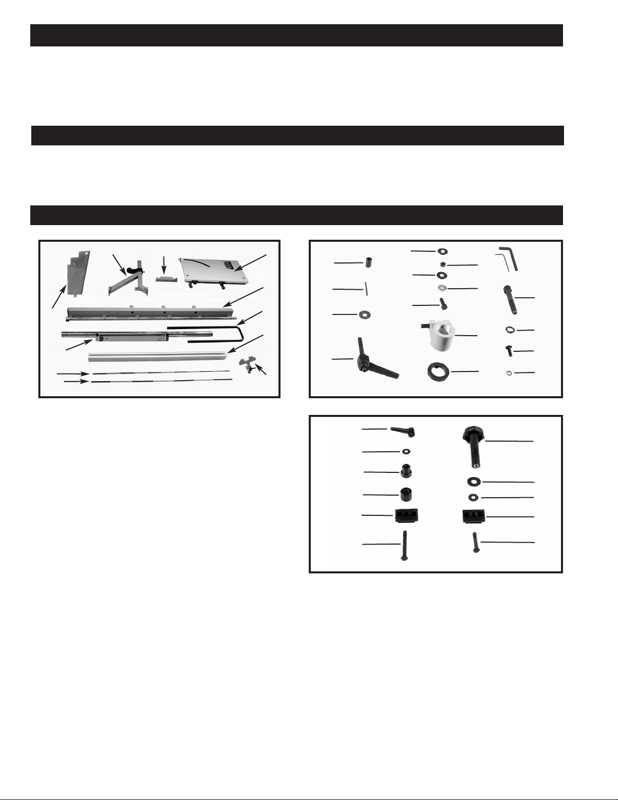
CARTON CONTENTS
Fig. 1
Fig. 2
1
2
8
7
6
4
5
3
9
10
1. Table Assembly
2. Upper Rail Assembly
3. Handle
4. Fence
5. Fence Stop Assembly
6. English (Inch) Scale
7. Metric Scale
8. Lower Rail Assembly
9. Sheet Metal Bracket
10. Table Assembly Support Frame
11. Handle Support Bracket
12. Lock Handle Assembly
13. 5/16" Flat Washer
14. Roll Pin
15. Rear Fence Cam
16. Rubber Bumper Stop
17. Table lock/stop Bracket
18. 1" Hex Head Screw
19. Special Washer (2)
20. 5/16" Flat Washer
21. 5/16" Hex Nut (2)
22. 5/16" Flat Washer (4)
23. 1/4" Lockwasher (4)
24. 3/4" Screw (4)
25. Lockwasher (3)
26. 2-1/2"Socket Head Cap Screw (3)
Fig. 3
12
13
14
15
16
18
19
20
21
22
17
23
24
25
26
27
28
29
30
31
32
33
34
35
36
37
38
27. Hex Head Wrenches
28. Ratchet Handle
29. 5/16" Flat Washer
30. Rear Fence Cam
31. Spacer
32. Slide Bracket
33. Special Bolt
34. Lock Knob
35. Nylon Flat Washer
36. 5/16" Flat Washer
37. Slide Bracket
38. Special Bolt
11
Page 5
5
ASSEMBLY
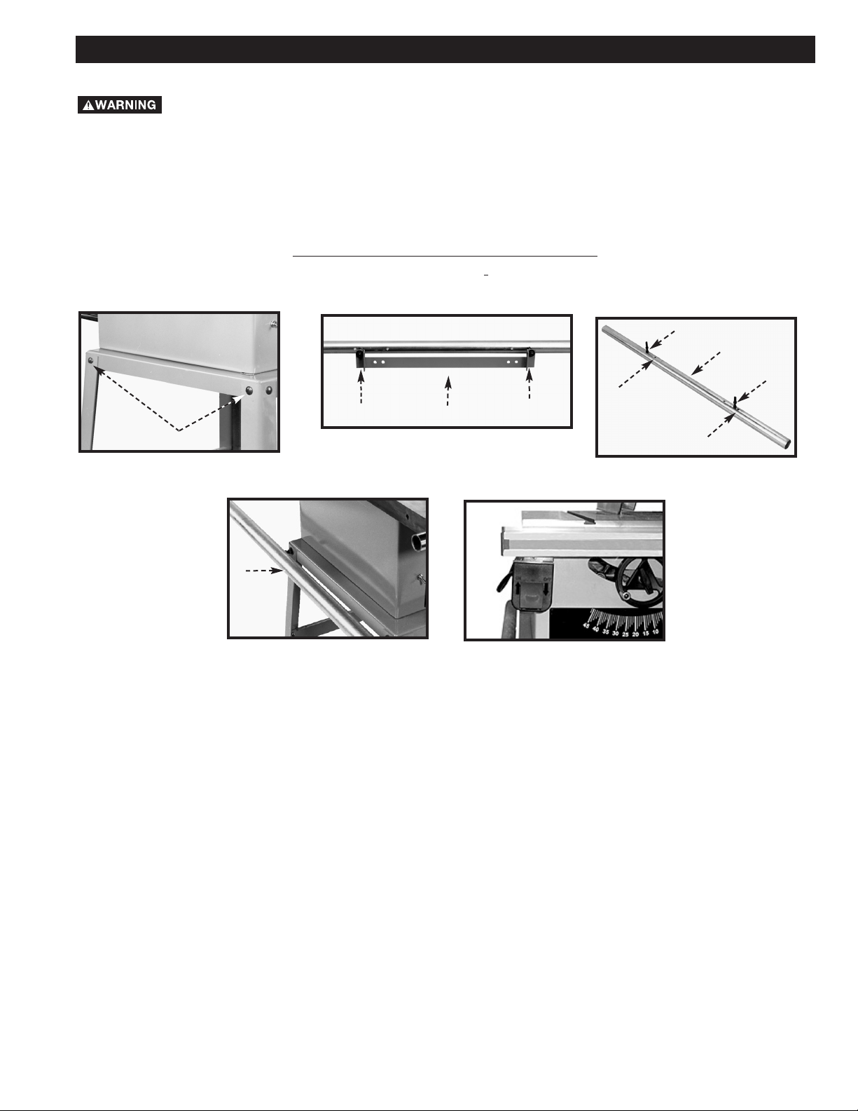
If your saw is equipped with the Delta Jet-Lock Rip Fence with round guide rails, cut 5-1/2" off of the left end of both
the front and rear guide rails. If your saw is equipped with a Beisemeyer fence, measure 1-1/2" to the left from the left
side of the table and cut the rail. If your saw is equipped with the Delta Unifence Saw Guide, cut 8" off the left end of
the front guide rail. Another option for the old Unifence is to redrill the mounting holes in the front guide rail 8" to the
left and reposition the rip scale. On the new Unifence, the rail can slide by loosening the two bolts and repositioning
the rip scale.
DISCONNECT MACHINE FROM POWER SOURCE.
Fig. 4
Fig. 5
Fig. 6
A
Fig. 7
E
D
F
D
E
F
B
B
C
(Contractor II Saws and Contractor Saw (Current Style) instructions follow in another section).
1. If your switch is attached to the left extension wing, remove it. (After installation of the sliding table, re-attach the
switch to the location shown in Fig. 8).
2. Remove the left-hand table extension. (It will not be used with the Sliding Table.)
3. Remove the two top left carriage bolts (A) Fig. 4, washers, and nuts from saw stand and discard. Enlarge the holes
using a 7/16" drill bit.
4. Locate the lower rail assembly (Fig. 5), and remove one nut and washer (B) from each side. Remove the mounting
bracket (C). (It is not used in this assembly.)
NOTE: Save the two nuts and washers (B) for use later.
5. Move the studs (E) Fig. 6 on the lower guide rail (F) to the holes (D) in the guide rail. Holes should be 20-1/4" apart.
6. Attach the lower guide rail (F) Fig. 7 to the two holes in the stand using the two flat washers and nuts that were
removed from the lower rail assembly in STEP 3.
NOTE: Position the end of the rail (F) Fig. 7 with the stud closest to the end toward the front.
7. Tighten the four nuts that attach the guide rail (F) Fig. 7 to the stand. Leave a space of 1-1/4" between the guide
rail and the stand. Final adjustments will be made later.
FOR 10" CONTRACTOR’S SAWS
(OLD STYLE)
Fig. 8
Page 6

6
FOR 10" CONTRACTOR’S SAWS
(CURRENT STYLE)
Fig. 9
Fig. 10
1. If your switch is attached to the left extension wing, remove it. (After installation of the sliding table, re-attach
the switch to the location shown in Fig. 9.)
2. Remove the left-hand table extension. (It will not be used with the Sliding Table.)
3. Confirm that the rail/bracket has been assembled as shown in Fig. 9, and that the short end of the rail (stud
closest to the end) is on the right. (If the rail has been previously attached with the long end of the rail to the
right, remove the bracket, turn the rail 180 degrees, and re-attch the bracket.
4. Locate the lower rail assembly (Fig. 9), two 1" hex head screws, two flat washers, two special washers, and
two hex nuts.
5. Attach the rail as assembled (Fig. 10). Place the studs in the holes on the lower guide rail. These studs should
be 21-3/4" apart.
6. Hold the lower rail assembly against the saw cabinet (Fig. 10) and mark and drill the two mounting holes in the
side of the leg panels using a 7/16" drill. NOTE: Hold the rail assembly level with the bottom edge of the saw
cabinet.
7. Fasten the lower rail assembly to the left side of the saw cabinet (Fig.10), using the hardware from Step 1.
Fig. 11
A
Fig. 14
F
G
E
FOR 10" CONTRACTOR II SAWS ONLY
Fig. 12
Fig. 13
F
D
E
B
B
C
1. If your switch is attached to the left extension wing, remove it. (After installation of the sliding table, re-attach the
switch to the location shown in Fig. 6C.)
2. Remove the left-hand table extension. (It will not be used with the Sliding Table.)
3. Remove the two top left carriage bolts (A) Fig. 11, washers and nuts from saw stand and discard. Enlarge the holes
using a 7/16" drill bit.
4. Locate the lower rail assembly (Fig. 12), and remove one nut and washer (B) from each side. Remove the mounting
bracket (C) Fig. 12.
NOTE: Discard the bracket, but save the two nuts and washers (B) Fig. 12. They will be used to mount the rail to the
stand.
5. Move the stud (E) Fig. 13 on the lower guide rail (F) to hole (D) in the guide rail. Hole spacing should be 18-1/4".
6. Attach the lower guide rail (E) Fig. 19 to the two holes in the stand, using the two flat washers and nuts that were
removed from the lower rail assembly in STEP 2.
NOTE: Place the long end of rail (E) Fig. 19 (stud farthest from the end) toward the front.
7. Tighten the four nuts that attach the guide rail (F) Fig. 19 to the stand. Leave a space of 2-1/8" between the guide
rail and the stand. Final adjustments will be made later.
Page 7

7
Fig. 15
Fig. 16
FOR 10" TILTING ARBOR SAWS ONLY
1. Remove the motor cover. (To use the Sliding table, replace the motor cover with the part #734557 Hinged Motor
Cover. Refer to the instructions that accompany the cover for installation.)
2. Locate the rail (Fig.15), two 1" hex head screws, 2 flat washers, 2 special washers, and 2 hex nuts. Make sure that
the rail/bracket is assembled as shown in Fig. 15, and that the short end of the rail is on the right of the bracket.
(If the rail has been previously attached with the long end to the right, remove the bracket, turn the rail 180 degrees,
and re-attach the bracket.)
3. Measure down 21" from the surface of the saw table, draw a line, then hold up the rail (with the short end of the
rail to the front of the saw) and mark the drill guides on the marked line. Drill 7/16" holes at these marked locations.
4. Fasten the lower rail assembly to the saw cabinet (Fig. 16), using the hardware From STEP 1.
NOTE: Position the special washers between the lower rail mounting bracket and the cabinet. Place the lockwashers
and nuts inside the cabinet. Make sure that the head of the bolts and flat washers are on the outside of the mounting
brackets.
Fig. 17
J
J
FOR HEAVY DUTY SHAPERS ONLY
Fig. 20
Fig. 21
K
Fig. 22
K
J
1. If your switch bracket looks the same as the bracket in Fig 18, order a new switch bracket (#432-02-014-0017)
that looks the same as the bracket in Fig. 19 .
2. Remove the front table extension.
3. Locate the rail (Fig.20), two 1" hex head screws, 2 flat washers, 2 special washers, and 2 hex nuts. Make sure that
the rail/bracket is assembled as shown in Fig. 20, and that the short end of the rail (stud closest to the end) is on
the right of the bracket. (If the rail has been previously attached with the long end to the right, remove the bracket,
turn the rail 180 degrees, and re-attach the bracket.)
4. Measure down 21" from the surface of the shaper table and draw a line on the cabinet door side (Fig. 22). Hold
the rail against the cabinet with the short end of the rail to the front of the saw, and mark the drill guides on the
marked line. Drill 7/16" holes at these marked locations (J) Fig. 22.
5. Fasten the lower rail assembly to the front side of the shaper cabinet (Fig. 21), using the hardware From STEP 1.
NOTE: Position the special washers between the lower rail mounting bracket and the cabinet. Place the lockwashers
and nuts inside the cabinet. Make sure that the head of the bolts and flat washers are on the outside of the mounting
brackets.
Fig. 18
Fig. 19
Page 8

1. Attach the upper rail assembly (L) Fig. 27 to the side of the table where the extension wing was previously
mounted, using the three 2-1/2" socket head screws (M) and lockwashers (N) through the holes (C) Fig. 28.
2. Use a square (D) Fig. 28 with a straight edge (A) on the machine table with the other end extending over the top
of the upper rail assembly (B). The top of the upper rail assembly (B) must be slightly below the table surface.
Check the square (A) to confirm that the rail (E) is the same distance below the table surface at the front and the
rear. To adjust, loosen the three screws located in holes (C) and adjust the upper guide rail assembly (B). After
adjustment, tighten screws (C).
4. Attach the table support frame (P) Fig. 29 to the bottom of the table assembly using the four 3/4" screws (Q) and
1/4" lockwashers (R).
5. Insert the long end of the handle (S) Fig. 30 through the hole in the table support frame (P).
6. Place the 5/16" flat washer (T) Fig. 31 on the shaft end of the lock handle assembly (U) and place the handle
support bracket (V) in position over the handle (S). Insert the threaded end of the handle assembly (U) through the
hole (W) in the support bracket (V) and tighten the handle assembly (U).
7. Insert the roll pin (X) in the end of the handle rod (S) Fig. 32.
The roll pin (X) prevents the handle (S) from pulling out of the support frame (P).
8. Slide the table assembly on the upper rail with the handle (S) Fig. 33 in the front position.
The guide rail (C) must be between the two V roller bearings and the two flat roller bearings underneath the
table assembly (Fig 35).
9. Make sure lower bearing (Y) Fig. 34, contacts lower rail (F) in the center of the rail. If necessary, loosen screw (Z)
and move bracket (A) up or down until bearing (Y) contacts rail (F).
FOR ALL PRODUCTS
NOTE:
NOTE:
8
Fig. 25
J
FOR 10" RIGHT-TILT UNISAWS ONLY
Fig. 23
Fig. 24
1. If the switch is mounted to the left table extension, remove the switch and
discard the hardware.
2. Remove the left-hand table extension. (It will not be used with the sliding
table.)
3. Locate the rail (Fig.23), two 1" hex head screws, 2 flat washers, 2 special
washers, and 2 hex nuts. Make sure that the rail/bracket is assembled as
shown in Fig. 20, and that the short end of the rail is on the right of the
bracket. (If the rail has been previously attached with the long end to the
right, remove the bracket, turn the rail 180 degrees, and re-attach the
bracket.)
4. Measure down 19-3/4" from the top surface of the saw table, draw a line,
then hold up the rail (with the short end of the rail to the front of the saw). Mark the drill guides on the marked line.
Drill 7/16" holes at these marked locations.
5. Fasten the lower rail assembly to the left side of the saw cabinet (Fig. 24), using the hardware From STEP 1.
NOTE: Position the special washers between the lower rail mounting bracket and the cabinet. Place the lockwashers
and nuts inside the cabinet. Make sure that the head of the bolts and flat washers are on the outside of the
mounting brackets.
6. If your unit has the GPE switch (different from the one in Fig. 26), remove the bracket from the switch and attach
the sheet metal bracket (#9 in CARTON CONTENTS). Attach it by moving from the original position to the position
shown in Fig. 26.
7. If your unit has the LVC switch, use the front rail mounting hardware and secure it with the nut on the backside.
Attach this assembly in the same location and with the same hardware as in STEP 6.
Fig. 26
Page 9

99
Fig. 27
Fig. 28
Fig. 29
Fig. 30
Fig. 31
L
M N
C
E
B
D
A
R
Q
Q
P
S
P
W
U
T
S
V
Fig. 32
Fig. 33
Fig. 34
P
S
X
S
E
Z
A
Y
F
Fig. 35
Fig. 36
E
F
B
D
C
C
H
G
Fig. 37
F
Y
J
Fig. 38
K
M
L
For Old Contractor’s Saws, turn bracket (A) Fig. 34 upside down so that the bearing (Y) contacts the rail (F).
10. Adjust the two lower bearings, one of which is shown at (B) Fig. 35, so that the upper guide rail (C) will be between
the two lower bearings (B) and two upper bearings (D). Adjust the bearing (B) by loosening the nut (E) and turning
the eccentric (F) to move the bearing (B) up or down. Adjust the rear bearing in the same manner.
This is a temporary adjustment. The final adjustment will be made later.
11. Attach the rubber bumper stop (G) Fig. 36, and table lock/stop bracket (H) to the front end of the upper rail (C).
12. Pull the sliding table toward the front of the saw until the lower bearing (Y) Fig. 37 is near the end of the lower rail
(F).
13. Push the rubber bumper stop (G) Fig. 36 and the table lock/stop bracket (H) in until they contact the upper bearing
on the sliding table. Tighten the set screw (J) Fig. 36 to hold the stop (H) in place.
14. Fig. 38 illustrates the sliding table (K) locked in the forward position. The lock pin (L) is moved to the left through
the hole (M) in the table bracket to lock the table in place. To slide the table on the rail, move the lock pin (L) to
the right.
NOTE:
NOTE:
Page 10

10
Fig. 43
Fig. 44
F
G
H
F
G
Fig. 39
Fig. 40
Fig. 41
Fig. 42
N
P
R
V
S
N
P
R
X
Y
W
C
D
E
C
E
NOTE: Never operate the sliding table with the table lock/stop bracket removed.
15. Place the special threaded bolt (N) Fig. 39 through the hole in the slide bracket (P) and the spacer and flat washer (R),
then through the bushing (S) in the table and frame. Fasten in place with a flat washer and knob (V) from underneath the
table. Make sure that the hex head on the bolt seats in the hex on the slide bracket.
16. Place the special threaded bolt (N) Fig. 40 through the hole in the remaining slide bracket (P) and the spacer (R) then
down through the hole in the sliding bracket (W). Fasten in place with a flat washer (X) and locking lever (Y).
17. Insert the rear fence cam (C) Fig. 41 into hole (D) in the bracket. Tighten the set screw (E) Fig. 41 and Fig. 42 to hold the
cam (C) in place. Adjustment to the cam (C) will be made later.
18. Attach fence (F) Fig. 43 to right fence clamp (G) and into left fence clamp (H) Fig. 44.
19. After the fence is attached to the sliding table, tighten the fence lock handle (G) Fig. 44 and lock knob (J) Fig 47.
20. Attach the fence stop assembly (K) Fig. 45 to the top of the fence and tighten the lock handle (L).
21. Position fence (F) Fig. 46 on the table to provide a clearance of 1/4" or more between the right end of fence (F) and the
blade guard. Place a 12" rule (M) against the saw blade and along the fence. Loosen the lock handle (L) and move the
stop (N) against end of rule (M) to place it 12" from the blade.
22. Decide whether to use the metric or English scale. Peel the backing from the scale. (The English scale is used in these
examples.) Apply the scale inside the fence channel, lining up the 12" mark on the scale with the pointer (O) Fig. 48.
Make adjustments to the pointer (O) by loosening the screw (R), adjusting the pointer (O) and tightening the screw (R).
Fig. 45
Fig. 46
L
K
L
N
M
Fig. 48
P
O
R
F
SCALE
J
Fig. 47
Page 11

11
H
C
A
B
Fig. 50
Fig. 51
Fig. 52
Fig. 53
Fig. 54
A
B
C
A
B
C
F
G E
D
K
F
G
E
H
J
M
L
ADJUSTING HEIGHT OF RIGHT EDGE OF SLIDING TABLE
L
The right edge of the sliding table should be slightly higher than the machine table, both front and rear. To check and adjust:
1. Use the fence (A) Figs. 49 and 50 or a suitable straight edge to see if the sliding table (B) is slightly higher than the
machine table (C) at the front of the machine table (Fig. 49) and the rear of the machine table (Fig. 50).
2. The height of the sliding table is controlled by raising or lowering the two sets of upper and lower bearings that ride on
the upper guide rail (K) Fig. 51. The front upper and lower bearings are shown at (D) and (E) Fig. 51.
NOTE: For clarity, the table/lock stop has been removed from the guide rail.
3. To adjust the lower bearing (E) Figs. 51 and 52 out of the way, loosen the nut (F) and turn the eccentric (G).
4. To adjust the upper bearing (D) Fig. 51, loosen the nut (H) Fig. 52, and turn the eccentric (J) until the table is slightly higher
than the saw table. Tighten the nut (H). Readjust the lower bearing. Maintain a smooth sliding fit between the bearings
and the upper guide rail.
5. IMPORTANT: If after adjusting, the height of the sliding table is still below the machine table surface, loosen the six
screws that fasten the upper rail (M) to the mounting bracket, five of which are shown at (L) Fig. 53. Raise the rail parallel
with the table surface. Then re-adjust the bearings.
Fig. 49
Fig. 55
D
H
G
E
F
ADJUSTING LOWER RAIL PARALLEL TO UPPER RAIL
To adjust the lower rail parallel to the upper rail:
1. Confirm that the fence is attached to the sliding table and that the right end of the fence extends across the surface of
the table to the miter gauge slot.
2. Confirm that the gap between the bottom of the fence and the table at points (A) and (B) Fig. 54 is equal.
3. Move the sliding table to the front of the saw until the fence is at the front edge of the table.
4. Make any adjustments with the two nuts (C) Fig. 54. The other nut is located inside the stand or cabinet on the old style
and contractor’s saw II. (For the other machines, both nuts are located on the bracket.) Adjusting the nuts (C) will move
the lower rail (H) closer to or farther away from other side of the bracket or the stand/cabinet. Do not adjust the nut next
to the guide rail (H). Adjust the nuts until the gap between the bottom of the fence and the table is the same at points
(A) and (B) Fig. 54.
5. Move the sliding table to the rear position until the bearing (D) Fig. 55 is positioned opposite the rear lower rail mounting
bolt (G).
6. Check the gap between the bottom of the fence and the saw table at points (E) and (F) Fig. 55 to see if the gap is the
same at both points.
7. Make any adjustments with the two nuts, one of which is shown at (G) Fig. 55. The other nut is located inside the stand
or cabinet on the contractor’s saw. (For the other machines, both nuts are located on the bracket.) Adjusting the nuts
(G) will move the lower rail (H) closer to or farther away from the other side of the bracket or the stand/cabinet. Do not
adjust the nut next to the guide rail (H). Adjust the nuts until the gap between the bottom of the fence and the table is
the same at points (E) and (F) Fig. 55.
Page 12

Adjust the sliding table so that it is parallel with the machine table. (The sliding table must also be slightly higher
than the machine table.) To check and adjust:
Fig. 56 Fig. 57
A
B
C
E
F
D
ADJUSTING SLIDING TABLE PARALLEL WITH MACHINE TABLE
L
12
1. Place a straight edge or the fence (A) Fig. 56 over the sliding table (B) and machine table (C).
2. The sliding table (B) Fig. 56 should be parallel with the machine table (C).
3. To adjust, loosen locknut (D) Fig. 57 and turn eccentric (E) to move bearing (F) in or out. Moving bearing (F) will raise or
lower the right end of the sliding table. After adjustment is complete, tighten locknut (D).
ADJUSTING FENCE 90 AND 45 DEGREE POSITIVE STOPS
Positive stops are provided on the fence mounting bracket of your sliding table that will enable you to rapidly position
the fence at 90 and 45 degrees to the blade. To check and adjust the fence positive stops:
1. With the fence (A) Fig. 58 in the forward operating position on the sliding table, loosen both fence locking handles,
one of which is shown at (B). Pull the left end of fence as far toward the front as possible and tighten both locking
handles (B).
2. Place a square against the fence and the saw blade to check for a 90 degree angle. If the angle is incorrect, refer
to STEP 4. Remove the square and connect the machine to the power source.
3. Make a test cut on a piece of stock (Fig. 59). Make sure that the edge of the stock against the fence is straight.
Check to see that the cut portion of the stock is 90 degrees to the edge of the stock (against the fence). If the cut
is not 90 degrees, refer to STEP 4.
4. Loosen the locknut (C) Fig. 60 and adjust the screw (D) until it contacts the bracket (E) with the fence 90 degrees
to the blade. Tighten the locknut (C). Connect the machine to the power source, and make additional cuts until
the cut is 90 degrees.
5. After adjusting the fence positive stops, check the miter scale (M) Fig. 64. To adjust, loosen the two screws, one
of which is shown at (N). Adjust the scale (M) and tighten the screws (N).
6. Loosen both fence locking handles and rotate left end of fence (A) to the rear until the pointer aligns with the 45
degree mark on the scale. (Fig. 61). Tighten both fence locking handles.
NOTE: When moving the left end of the fence for miter cutting, slide the fence by moving the lock handle (B) Fig. 60
with your hand.
7. Make a test cut on a piece of stock (Fig. 62). (Make sure that the edge of the stock against the fence is straight.
If the cut is not 45 degrees to the edge against the fence, refer to STEP 8.
8. Loosen the locknut (F) Fig. 63 and adjust the screw (G) until it contacts the bracket (H) with the fence at 45 degrees
to the blade. Tighten the locknut (F).
9. Move the fence (A) Fig. 65 to the rear operating position by following the instructions “MOVING FENCE TO REAR
POSITION ON SLIDING TABLE” later in this manual. Tighten both fence locking handles.
10. Place a square against the fence and the saw blade to check for a 90 degree angle. If the angle is incorrect, refer
to STEP 12. Remove the square and connect the machine to the power source.
11. Make a test cut on a piece of stock (Fig. 66).Make sure that the edge of the stock against the fence is straight.
See if the cut is 90 degrees to the edge (against the fence). If the cut was not 90 degrees, refer to STEP 12.
12. Slightly loosen both fence locking handles. Loosen the set screw (J) Fig. 67. Use a nail or some other suitable
instrument in the hole (K) to rotate the eccentric bushing (L) until the fence is 90 degrees to the blade. Tighten the
set screw (J). Connect the machine to the power source and make additional test cuts until the cut is 90 degrees.
DISCONNECT MACHINE FROM POWER SOURCE.
DISCONNECT MACHINE FROM POWER SOURCE.
DISCONNECT MACHINE FROM POWER SOURCE.
DISCONNECT MACHINE FROM POWER SOURCE.
Page 13

13
Fig. 66
Fig. 64
Fig. 65
A
Fig. 58
Fig. 59
A
Fig. 60
Fig. 61
Fig. 62 Fig. 63
B
B
E
C
D
A
G
F
H
Fig. 67
K
L
J
N
M
Page 14

1414
Fig. 68
1. Loosen the clamp handle (A) and the clamp knob (D) Fig. 68. Slide the fence (C) Fig. 68 from the two fence clamps (B).
2. Remove the fence locking handle, the clamp knob, and the fence clamps (B) and re-position the fence clamps (B), clamp
handle, and clamp knob to the rear of the sliding table (Fig. 68).
3. Slide the fence (C) Fig. 69 back on the fence clamps and tighten the lock handles, one of which is shown at (A).
NOTE: When the fence (C) is used in the rear table position (Fig. 69), flip the fence stop (D) to the front.
Fig. 69
A
B
C
A
C
D
MOVING FENCE TO REAR POSITION ON SLIDING TABLE
L
Fig. 70 Fig. 71
A
D
When you use the fence in the rear position, you increase your cut-off capacity from 24" to 36". To move the fence:
B
A
A handle (A) Figs. 70 and 71 (used to slide the table) is supplied on the front of the sliding table mechanism. Depending
on the size of the workpiece and/or operator convenience, you can move the handle (A) (Fig. 70) out by loosening the
clamp handle (B) Fig. 71, sliding the handle (A) to the desired position, and tightening the clamp handle (B).
Page 15

15
PARTS, SERVICE OR WARRANTY ASSISTANCE
All Delta Machines and accessories are manufactured to high quality standards and are serviced by a network
of Porter-Cable • Delta Factory Service Centers and Delta Authorized Service Stations. To obtain additional
information regarding your Delta quality product or to obtain parts, service, warranty assistance, or the location
of the nearest service outlet, please call 1-800-223-7278 (In Canada call 1-800-463-3582).
Two Year Limited New Product Warranty
Delta will repair or replace, at its expense and at its option, any new Delta machine, machine part, or machine accessory
which in normal use has proven to be defective in workmanship or material, provided that the customer returns the product
prepaid to a Delta factory service center or authorized service station with proof of purchase of the product within two
years and provides Delta with reasonable opportunity to verify the alleged defect by inspection. For all refurbished Delta
product, the warranty period is 180 days. Delta may require that electric motors be returned prepaid to a motor
manufacturer’s authorized station for inspection and repair or replacement. Delta will not be responsible for any asserted
defect which has resulted from normal wear, misuse, abuse or repair or alteration made or specifically authorized by
anyone other than an authorized Delta service facility or representative. Under no circumstances will Delta be liable for
incidental or consequential damages resulting from defective products. This warranty is Delta’s sole warranty and sets
forth the customer’s exclusive remedy, with respect to defective products; all other warranties, express or implied, whether
of merchantability, fitness for purpose, or otherwise, are expressly disclaimed by Delta.
Page 16

The following are trademarks of PORTER-CABLE·DELTA (Las siguientes son marcas registradas de PORTER-CABLE S.A.): Auto-Set®,
BAMMER®, B.O.S.S.®, Builder’s Saw®, Contractor’s Saw®, Contractor’s Saw II™, Delta®, DELTACRAFT®, DELTAGRAM™, Delta Series
2000™, DURATRONIC™, Emc²™, FLEX®, Flying Chips™, FRAME SAW®, Homecraft®, INNOVATION THAT WORKS®, Jet-Lock®,
JETSTREAM®, ‘kickstand®, LASERLOC®, MICRO-SET®, Micro-Set®, MIDI LATHE®, MORTEN™, NETWORK™, OMNIJIG®, POCKET
CUTTER®, PORTA-BAND®, PORTA-PLANE®, PORTER-CABLE®&(design), PORTER-CABLE®PROFESSIONAL POWER TOOLS, Posi-Matic®,
Q-3®&(design), QUICKSAND®&(design), QUICKSET™, QUICKSET II®, QUICKSET PLUS™, RIPTIDE™&(design), SAFE GUARD II®, SAFELOC®, Sanding Center®, SANDTRAP®&(design), SAW BOSS®, Sawbuck™, Sidekick®, SPEED-BLOC®, SPEEDMATIC®, SPEEDTRONIC®,
STAIR EASE®, The American Woodshop®&(design), The Lumber Company®&(design), THE PROFESSIONAL EDGE®, THE PROFESSIONAL
SELECT®, THIN-LINE™, TIGER®, TIGER CUB®, TIGER SAW®, TORQBUSTER®, TORQ-BUSTER®, TRU-MATCH™, TWIN-LITE®,
UNIGUARD®, Unifence®, UNIFEEDER™, Unihead®, Uniplane™, Unirip®, Unisaw®, Univise®, Versa-Feeder®, VERSA-PLANE®, WHISPER
SERIES®, WOODWORKER’S CHOICE™.
Trademarks noted with ™ and ® are registered in the United States Patent and Trademark Office and may also be registered in other
countries. Las Marcas Registradas con el signo de ™ y ® son registradas por la Oficina de Registros y Patentes de los Estados Unidos y
también pueden estar registradas en otros países.
PORTER-CABLE • DELTA SERVICE CENTERS
(CENTROS DE SERVICIO DE PORTER-CABLE
• DELTA)
Parts and Repair Service for Porter-Cable •Delta Machinery are Available at These Locations
(Obtenga Refaccion de Partes o Servicio para su Herramienta en los Siguientes Centros de Porter-Cable
•
Delta)
Authorized Service Stations are located in many large cities. Telephone 800-438-2486 or 731-541-6042 for assistance locating one.
Parts and accessories for Porter-Cable
·
Delta products should be obtained by contacting any Porter-Cable·Delta Distributor, Authorized
Service Center, or Porter-Cable
·
Delta Factory Service Center. If you do not have access to any of these, call 800-223-7278 and you will
be directed to the nearest Porter-Cable
·
Delta Factory Service Center. Las Estaciones de Servicio Autorizadas están ubicadas en muchas
grandes ciudades. Llame al 800-438-2486 ó al 731-541-6042 para obtener asistencia a fin de localizar una. Las piezas y los accesorios
para los productos Porter-Cable
·
Delta deben obtenerse poniéndose en contacto con cualquier distribuidor Porter-Cable·Delta, Centro
de Servicio Autorizado o Centro de Servicio de Fábrica Porter-Cable
·
Delta. Si no tiene acceso a ninguna de estas opciones, llame al
800-223-7278 y le dirigirán al Centro de Servicio de Fábrica Porter-Cable
·
Delta más cercano.
ARIZONA
Tempe 85282 (Phoenix)
2400 West Southern Avenue
Suite 105
Phone: (602) 437-1200
Fax: (602) 437-2200
CALIFORNIA
Ontario 91761 (Los Angeles)
3949A East Guasti Road
Phone: (909) 390-5555
Fax: (909) 390-5554
San Leandro 94577 (Oakland)
3039 Teagarden Street
Phone: (510) 357-9762
Fax: (510) 357-7939
COLORADO
Arvada 80003 (Denver)
8175 Sheridan Blvd., Unit S
Phone: (303) 487-1809
Fax: (303) 487-1868
FLORIDA
Davie 33314 (Miami)
4343 South State Rd. 7 (441)
Unit #107
Phone: (954) 321-6635
Fax: (954) 321-6638
Tampa 33609
4538 W. Kennedy Boulevard
Phone: (813) 877-9585
Fax: (813) 289-7948
GEORGIA
Forest Park 30297 (Atlanta)
5442 Frontage Road,
Suite 112
Phone: (404) 608-0006
Fax: (404) 608-1123
ILLINOIS
Addison 60101 (Chicago)
400 South Rohlwing Rd.
Phone: (630) 424-8805
Fax: (630) 424-8895
Woodridge 60517 (Chicago)
2033 West 75th Street
Phone: (630) 910-9200
Fax: (630) 910-0360
MARYLAND
Elkridge 21075 (Baltimore)
7397-102 Washington Blvd.
Phone: (410) 799-9394
Fax: (410) 799-9398
MASSACHUSETTS
Braintree 02185 (Boston)
719 Granite Street
Phone: (781) 848-9810
Fax: (781) 848-6759
Franklin 02038 (Boston)
Franklin Industrial Park
101E Constitution Blvd.
Phone: (508) 520-8802
Fax: (508) 528-8089
MICHIGAN
Madison Heights 48071 (Detroit)
30475 Stephenson Highway
Phone: (248) 597-5000
Fax: (248) 597-5004
MINNESOTA
Minneapolis 55429
5522 Lakeland Avenue North
Phone: (763) 561-9080
Fax: (763) 561-0653
MISSOURI
North Kansas City 64116
1141 Swift Avenue
Phone: (816) 221-2070
Fax: (816) 221-2897
St. Louis 63119
7574 Watson Road
Phone: (314) 968-8950
Fax: (314) 968-2790
NEW YORK
Flushing 11365-1595 (N.Y.C.)
175-25 Horace Harding Expwy.
Phone: (718) 225-2040
Fax: (718) 423-9619
NORTH CAROLINA
Charlotte 28270
9129 Monroe Road, Suite 115
Phone: (704) 841-1176
Fax: (704) 708-4625
OHIO
Columbus 43214
4560 Indianola Avenue
Phone: (614) 263-0929
Fax: (614) 263-1238
Cleveland 44125
8001 Sweet Valley Drive
Unit #19
Phone: (216) 447-9030
Fax: (216) 447-3097
OREGON
Portland 97230
4916 NE 122 nd Ave.
Phone: (503) 252-0107
Fax: (503) 252-2123
PENNSYLVANIA
Willow Grove 19090
520 North York Road
Phone: (215) 658-1430
Fax: (215) 658-1433
TEXAS
Carrollton 75006 (Dallas)
1300 Interstate 35 N, Suite 112
Phone: (972) 446-2996
Fax: (972) 446-8157
Houston 77055
West 10 Business Center
1008 Wirt Road, Suite 120
Phone: (713) 682-0334
Fax: (713) 682-4867
WASHINGTON
Auburn 98001(Seattle)
3320 West Valley HWY, North
Building D, Suite 111
Phone: (253) 333-8353
Fax: (253) 333-9613
Printed in U.S.A. PC-0403-149
CANADIAN PORTER-CABLE • DELTA SERVICE CENTERS
ALBERTA
Bay 6, 2520-23rd St. N.E.
Calgary, Alberta
T2E 8L2
Phone: (403) 735-6166
Fax: (403) 735-6144
BRITISH COLUMBIA
8520 Baxter Place
Burnaby, B.C.
V5A 4T8
Phone: (604) 420-0102
Fax: (604) 420-3522
MANITOBA
1699 Dublin Avenue
Winnipeg, Manitoba
R3H 0H2
Phone: (204) 633-9259
Fax: (204) 632-1976
ONTARIO
505 Southgate Drive
Guelph, Ontario
N1H 6M7
Phone: (519) 836-2840
Fax: (519) 767-4131
QUÉBEC
1515 ave.
St-Jean Baptiste,
Québec, Québec
G2E 5E2
Phone: (418) 877-7112
Fax: (418) 877-7123
1447, Begin
St-Laurent, (Montréal),
Québec
H4R 1V8
Phone: (514) 336-8772
Fax: (514) 336-3505
 Loading...