

Page 1
DELTA 6 in. x 89 in. OsciLLATing
EDgE sAnDEr
Ponceuse oscillante pour champs de
15,24 cm x 226,06 cm
Lijadora de borde oscilante de
15,24 cm x 226,06 cm
Français (16)
Español (30)
www.DeltaMachinery.com
Operating Instructions and Parts Manual
Manuel d’utilisation
Manual de instrucciones
INSTRUCTIVO DE OPERACIÓN, CENTROS
DE SERVICIO Y PÓLIZA DE GARANTÍA.
LÉASE ESTE INSTRUCTIVO
ANTES DE USAR EL PRODUCTO.
31-482
Page 2

TABLE OF CONTENTS
IMPORTANT SAFETY INSTRUCTIONS ................................... 2
SAFETY GUIDELINES - DEFINITIONS .................................... 3
GENERAL SAFETY RULES ...................................................... 3
POWER CONNECTIONS .......................................................... 5
MOTOR SPECIFICATIONS ....................................................... 5
GROUNDING INSTRUCTIONS ................................................ 5
EXTENSION CORDS ................................................................ 6
KEY FEATURES AND COMPONENTS .................................... 6
FUNCTIONAL DESCRIPTION .................................................. 7
PRODUCT SPECIFICATIONS ................................................... 7
UNPACKING ..............................................................................7
ASSEMBLY ................................................................................ 8
Cabinet Assembly ............................................................... 8
Mounting the Table to the Cabinet ...................................... 8
Sanding Belt ........................................................................ 9
Drum Guard ......................................................................... 9
Contour Sanding Table ...................................................... 10
Workpiece Support ............................................................10
Sanding Fence ................................................................... 11
ADJUSTMENTS ....................................................................... 11
Changing the Sanding Angle ............................................ 11
Re-tensioning the Platen Locking Lever ........................... 11
Changing the Sanding Belt ............................................... 11
Adjusting the Belt Tracking................................................ 12
Adjusting the Motor Mount Tracking ................................ 12
Re-positioning the Table Height ........................................ 12
MAINTENANCE PROCEDURES ............................................ 13
Routine Inspection
Lubrication
Cleaning the Sanding Belts
TROUBLESHOOTING ............................................................. 13
ACCESSORIES ........................................................................ 14
WARRANTY .............................................................................14
FRANÇAIS ................................................................................ 16
ESPAÑOL .................................................................................32
IMPORTANT SAFETY INSTRUCTIONS
READ AND UNDERSTAND ALL WARNINGS AND OPERATING INSTRUCTIONS BEFORE USING THIS
EQUIPMENT. Failure to follow all instructions listed below, may result in electric shock, fire, and/or
serious personal injury or property damage.
Woodworking can be dangerous if safe and proper operating procedures are not followed. As with all
machinery, there are certain hazards involved with the operation of the product. Using the machine with
respect and caution will considerably lessen the possibility of personal injury. However, if normal safety
precautions are overlooked or ignored, personal injury to the operator may result. Safety equipment such
as guards, push sticks, hold-downs, featherboards, goggles, dust masks and hearing protection can reduce your
potential for injury. But even the best guard won’t make up for poor judgment, carelessness or inattention. Always
use common sense and exercise caution in the workshop. If a procedure feels dangerous, don’t try it. Figure out
an alternative procedure that feels safer. REMEMBER: Your personal safety is your responsibility. For additional
information please visit our website www.DeltaMachinery.com.
This machine was designed for certain applications only. DELTA® Power Equipment Corporation
strongly recommends that this machine not be modified and/or used for any application other than
that for which it was designed. If you have any questions relative to a particular application, DO NOT use the
machine until you have first contacted DELTA® to determine if it can or should be performed on the product.
If you have any questions relative to its application DO NOT use the product until you have written DELTA
Equipment Corporation and we have advised you. Contact us online at www.DeltaMachinery.com or by mail at
Technical Service Manager, DELTA® Power Equipment Corporation, 4825 Highway 45 North, Jackson, TN 38305.
Information regarding the safe and proper operation of this tool is available from the following sources:
• Power Tool Institute, 1300 Sumner Avenue, Cleveland, OH 44115-2851or online at www.powertoolinstitute.com
• National Safety Council, 1121 Spring Lake Drive, Itasca, IL 60143-3201
• American National Standards Institute, 25 West 43rd Street, 4 floor, New York, NY 10036 www.ansi.org - ANSI 01.1
Safety Requirements for Woodworking Machines
• U.S. Department of Labor regulations www.osha.gov
®
Power
2
Page 3

SAFETY GUIDELINES - DEFINITIONS
This manual contains information that is important for you to know and understand. This information relates to
protecting YOUR SAFETY and PREVENTING EQUIPMENT PROBLEMS. To help you recognize this information, we
use the symbols below. Please read the manual and pay attention to these sections.
Indicates an imminently hazardous situation which, if not avoided, will result in death or serious
injury.
Indicates a potentially hazardous situation which, if not avoided, could result in death or serious
injury.
Indicates a potentially hazardous situation which, if not avoided, may result in minor or moderate
injury.
Used without the safety alert symbol indicates potentially hazardous situation which, if not avoided,
may result in property damage.
GENERAL SAFETY RULES
WARNING FAILURE TO FOLLOW THESE RULES MAY RESULT IN SERIOUS PERSONAL INJURY.
FOR YOUR OWN SAFETY, READ AND UNDERSTAND THE INSTRUCTION MANUAL BEFORE OPERATING THE
•
UNIT.
Learn the unit’s application and limitations as well as the specific hazards peculiar to it.
KEEP WORK AREA CLEAN.
•
DON’T USE IN DANGEROUS ENVIRONMENT.
•
Keep work area well-lighted.
KEEP CHILDREN AND VISITORS AWAY.
•
DISCONNECT UNIT
•
CHECK DAMAGED PARTS.
•
before servicing.
Cluttered areas and benches invite accidents.
Don’t use this unit in damp or wet locations, or expose it to rain.
All children and visitors should be kept a safe distance from work area.
Before further use of the unit, properly repair or replace any part that is damaged.
FAILURE TO FOLLOW THESE RULES MAY RESULT IN SERIOUS INJURY.
1. Read and understand the warnings posted on the
machine and in this manual. Failure to comply with
all of these warnings may cause serious injury.
2. Replace the warning labels if they become
obscured or removed.
3. This Oscillating Edge Sander is designed
and intended for use by properly trained and
experienced personnel only. If you are not familiar
with the proper and safe operation of an edge
sander, do not use until proper training and
knowledge have been obtained.
4. Do not use this machine for other than its intended
use. If used for other purposes, Delta Power
Equipment Company, Inc. disclaims any real or
implied warranty and holds itself harmless from any
injury that may result from that use.
5. Always wear approved safety glasses/face shields
while using this Oscillating Edge Sander.
6. Before operating this edge sander, remove tie,
rings, watches and other jewelry, and roll sleeves
up past the elbows. Remove all loose clothing and
confine long hair. Non-slip footwear or anti-skid
floor strips are recommended. Do not wear gloves.
7. Wear ear protectors (plugs or muffs) during
extended periods of operation.
8. Some dust created by power sanding, sawing,
grinding, drilling and other construction activities
contain chemicals known to cause cancer,
birth defects or other reproductive harm. Some
examples of these chemicals are:
• Lead from lead based paint.
• Crystalline silica from bricks, cement and other
masonry products.
• Arsenic and chromium from chemically treated
lumber.
Your risk of exposure varies, depending on how often
you do this type of work. To reduce your exposure to
these chemicals, work in a well-ventilated area and
work with approved safety equipment, such as face or
dust masks that are specifically designed to filter out
microscopic particles.
1. Do not operate this machine while tired or under
the influence of drugs, alcohol or any medication.
2. Make certain the switch is in the OFF position
before connecting the machine to the power
source.
3. Make certain the machine is properly grounded.
4. Make all machine adjustments or maintenance with
the machine unplugged from the power source.
continued on page 4
3
Page 4

5. Form a habit of checking to see that all extra
equipment such as adjusting keys, wrenches,
scrap, stock, and cleaning rags are removed away
from the machine before turning on.
6. Keep safety guards in place at all times when the
machine is in use. If removed for maintenance
purposes, use extreme caution and replace the
guards immediately when maintenance is complete.
7. Make sure the edge sander is firmly secured to the
floor before use.
8. Check damaged parts. Before further use of the
machine, a guard or other part that is damaged
should be carefully checked to determine that it will
operate properly and perform its intended function.
Check for alignment of moving parts, binding of
moving parts, breakage of parts, mounting and
any other conditions that may affect its operation.
A guard or other part that is damaged should be
properly repaired or replaced.
9. Provide for adequate space surrounding work area
and non-glare, overhead lighting.
10. Keep the floor around the machine clean and free of
scrap material, oil and grease.
11. Keep visitors a safe distance from the work area.
Keep children away.
12. Make your workshop child proof with padlocks,
master switches or by removing starter keys.
13. Give your work undivided attention. Looking
around, carrying on a conversation and “horseplay” are careless acts that can result in serious
injury.
14. Maintain a balanced stance at all times so that you
do not fall or lean against the sanding belt or other
moving parts. Do not overreach or use excessive
force to perform any machine operation.
15. Use the right tool at the correct speed and feed
rate. Do not force a tool or attachment to do a job
for which it was not designed. The right tool will do
the job better and safer.
16. Use recommended accessories; improper
accessories may be hazardous.
17. Maintain machinery with care. Follow instructions
for lubricating and changing accessories.
18. Turn off the machine before cleaning. Use a brush
or compressed air to remove dust or debris — do
not use your hands.
19. Do not stand on the machine. Serious injury could
occur if the machine tips over.
20. Never leave the machine running unattended. Turn
the power off and do not leave the machine until it
comes to a complete stop.
21. At all times hold the stock firmly.
22. Do not use this sander for other than it intended
use. If used for other purposes, Delta Power
Equipment Company Inc., disclaims any real or
implied warranty and holds itself harmless for any
injury or damage which may result from that use.
SAVE THESE INSTRUCTIONS.
Refer to them often and use them to instruct others.
4
Page 5
POWER CONNECTIONS
A separate electrical circuit should be used for your machines. This circuit should not be less than #12 wire and
should be protected with a 20 Amp time lag fuse. If an extension cord is used, use only 3-wire extension cords
which have 3-prong grounding type plugs and matching receptacle which will accept the machine’s plug. Before
connecting the machine to the power line, make sure the switch (s) is in the "OFF" position and be sure that the
electric current is of the same characteristics as indicated on the machine. All line connections should make good
contact. Running on low voltage will damage the machine.
DO NOT EXPOSE THE MACHINE TO RAIN OR OPERATE THE MACHINE IN DAMP LOCATIONS.
MOTOR SPECIFICATIONS
Your machine is wired for 120/240 volts, 60 HZ alternating current. Before connecting the machine to the power
source, make sure the switch is in the "OFF" position.
GROUNDING INSTRUCTIONS
THIS MACHINE MUST BE GROUNDED WHILE IN USE TO PROTECT THE OPERATOR FROM
ELECTRIC SHOCK.
1. All grounded, cord-connected machines:
In the event of a malfunction or breakdown, grounding provides a path of least resistance for electric current to
reduce the risk of electric shock. This machine is equipped with an electric cord having an equipment-grounding
conductor and a grounding plug. The plug must be plugged into a matching outlet that is properly installed and
grounded in accordance with all local codes and ordinances.
Do not modify the plug provided - if it will not fit the outlet, have the proper outlet installed by a qualified electrician.
Improper connection of the equipment-grounding conductor can result in risk of electric shock. The conductor with
insulation having an outer surface that is green with or without yellow stripes is the equipment-grounding conductor.
If repair or replacement of the electric cord or plug is necessary, do not connect the grounding conductor to a live
terminal.
Check with a qualified electrician or service personnel if the grounding instructions are not completely understood,
or if in doubt as to whether the machine is properly grounded.
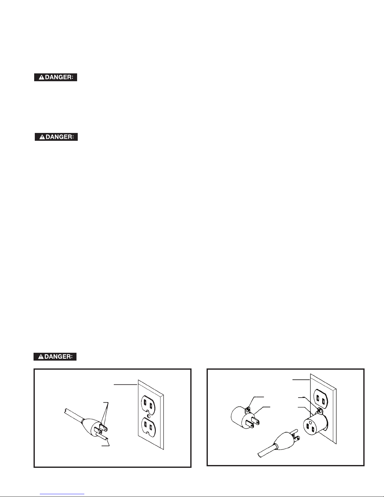
Use only 3-wire extension cords that have 3-prong grounding type plugs and matching 3-conductor receptacles that
accept the machine’s plug, as shown in Fig. A.
Repair or replace damaged or worn cord immediately.
2. Grounded, cord-connected machines intended for use on a supply circuit having a nominal rating less than
150 volts:
If the machine is intended for use on a circuit that has an outlet that looks like the one illustrated in Fig. A, the
machine will have a grounding plug that looks like the plug illustrated in Fig. A. A temporary adapter, which looks like
the adapter illustrated in Fig. B, may be used to connect this plug to a matching 2-conductor receptacle as shown
in Fig. B if a properly grounded outlet is not available. The temporary adapter should be used only until a properly
grounded outlet can be installed by a qualified electrician. The green-colored rigid ear, lug, and the like, extending
from the adapter must be connected to a permanent ground such as a properly grounded outlet box. Whenever the
adapter is used, it must be held in place with a metal screw.
NOTE: In Canada, the use of a temporary adapter is not permitted by the Canadian Electric Code.
IN ALL CASES, MAKE CERTAIN THE RECEPTACLE IN QUESTION IS PROPERLY GROUNDED.
IF YOU ARE NOT SURE, HAVE A QUALIFIED ELECTRICIAN CHECK THE RECEPTACLE.
GROUNDED
OUTLET BOX
CURRENT
CARRYING
PRONGS
GROUNDING BLADE
IS LONGEST OF THE 3 BLADES
FIG. A FIG. B
GROUNDED OUTLET BOX
GROUNDING
MEANS
ADAPTER
5
Page 6
3. 240 Volt Single-Phase Operation
The motor supplied with your machine is a dual voltage, 120/240 volt motor. It is shipped ready-to-run for 120 volt
operation. However, it can be converted for 240 volt operation.
A qualified electrician should do the conversion, or the machine can be taken to an Authorized Delta Service Center.
When completed, the machine must conform to the National Electric Code and all local codes and ordinances.
The machine is converted by re-wiring the motor for 240 volts, installing a 240 volt plug on the power supply cord and
replacing the switch with one that is rated for 240 volt operation. Be sure the 240 volt plug is only used in an outlet
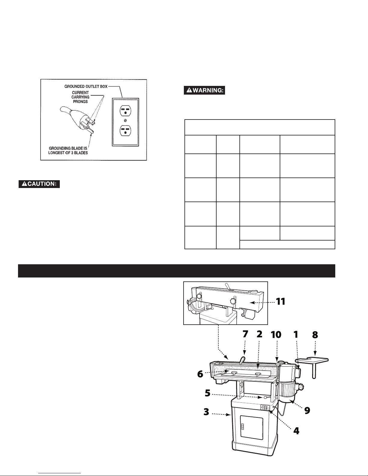
having the same configuration as the plug illustrated in Fig. C. No adapter should be used with the 240 volt plug.
In all cases, make certain that the
receptacle in question is properly
grounded. If you are not sure, have a qualified
electrician check the receptacle.
MINIMUM GAUGE EXTENSION CORD
RECOMMENDED SIZES FOR USE WITH STATIONARY ELECTRIC MACHINES
FIG. C
EXTENSION CORDS
Use proper extension cords. Make
sure your extension cord is in good
condition and is a 3-wire extension cord which has a
3-prong grounding type plug and matching
receptacle which will accept the machine’s plug.
When using an extension cord, be sure to use one
heavy enough to carry the current of the machine.
An undersized cord will cause a drop in line voltage,
resulting in loss of power and overheating. Fig. D
shows the correct gauge to use depending on the
cord length. If in doubt, use the next heavier gauge.
The smaller the gauge number, the heavier the cord.
Ampere
Rating
0-6
0-6
0-6
0-6
6-10
6-10
6-10
6-10
10-12
10-12
10-12
10-12
12-16
12-16
12-16
Volts Total Length
120
120
120
120
120
120
120
120
120
120
120
120
120
120
120
of Cord in
Feet
up to 25
25-50
50-100
100-150
up to 25
25-50
50-100
100-150
up to 25
25-50
50-100
100-150
up to 25
25-50
GREATER THAN 50 FEET NOT RECOMMENDED
FIG. D
Gauge of Extension
Cord
18 AWG
16 AWG
16 AWG
14 AWG
18 AWG
16 AWG
14 AWG
12 AWG
16 AWG
16 AWG
14 AWG
12 AWG
14 AWG
12 AWG
KEY FEATURES AND COMPONENTS
1-Dust Collection Port
2-Sanding Belt
3-Cabinet
4-Power Switch
5-Platen Lock
6-Support Fence
7-Belt Tensioning Lever
8-Contour Sanding Table
9-1-1/2HP Induction Motor
10-Workpiece Support
11-Rear Belt Guard
FIG. 1
6
Page 7

FUNCTIONAL DESCRIPTION
The DELTA® Oscillating Edge Sander is a professional-grade tool designed for both straight and angled edge-face
sanding as well as contour sanding. It is capable of sanding in either the vertical or horizontal plane. Your DELTA®
Oscillating Edge Sander comes with a 100 grit sanding belt and is mounted on a cabinet base that provides ample
storage space for accessories. This tool is powered by a 1-1/2HP, 120/240V induction motor that drives the sanding
belt and provides an oscillation stroke of ½” at a rate of 108 strokes per minute.
PRODUCT SPECIFICATIONS
Model 31-482
Fence (HxL) 4” x 24”
Abrasive Belt Size (WxL) 6” x 89”
Dust Chute Diameter 4”
Contour Sanding Table Size 9-3/4” x 11-3/4”
Table Size (LxW) 10” x 29-3/4”
Table Tilt 0-90°
Motor 1-1/2HP, 120/240V, 1PH, 60Hz, TEFC
Sanding Belt Speed 3900 FPM
Oscillation Stroke ½”
TOOLS NEEDED
FOR ASSEMBLY
• Two 12mm wrenches or
sockets
• 10mm wrench or socket
• Flat head screw driver
• Phillips head screw
driver
• Rubber mallet
Oscillations per Minute 108
Overall Dimensions (LxWxH) 51”x26.5”x20”
Net Weight, approximate 218
Shipping Weight, approximate 233
UNPACKING
Your Oscillating Edge Sander comes packed in a single container. Open the shipping container and check that all
parts are present and in good condition:
DESCRIPTION (QUANTITY)
Front Cabinet Panel with Door (1)
Rear Cabinet Panel (1)
Side Cabinet Panels (2)
Cabinet Shelf (1)
Rubber Feet (4)
Lock Knob - 35mm (1)
Lock Knob - 20mm (1)
Lock Knob - 12mm (2)
Contour Sanding Table (1)
Drum Guard/Dust Port (1)
Compare the contents of your container with the parts list to make sure all
parts are present and intact. Report any missing or damaged parts to your
distributor. Prior to tool assembly and use, read this manual thoroughly
to familiarize yourself with proper assembly, maintenance and safety
procedures.
Owner’s Manual (1)
Warranty Card (1)
Table Assembly (1)
Back Stop Bracket (1)
Belt Tension Handle (1)
Belt Tracking Tool (1)
Miter Gauge Assembly (1)
Sanding Belt (1)
Mounting Bracket (1)
HARDWARE
5/16” x 5/8” Screws (4)
5/16” Flat Washers (22)
5/16” Hex Nuts (12)
5/16” x 5/8” Hex Cap Bolts (8)
5/16” x 1-1/4” Hex Cap Bolts (2)
5/16” Flat Washers (4)
5/16” Lock Washers (10)
M5x10 Pan Head Screws (2)
M5 Flat Washers (2)
M5 Lock Washers (2)
1/4" x 5/8” Hex Cap Bolts (5)
1/4" Flat Washers (5)
1/4” Lock Washers (5)
10-24 x 3/4 Socket Head Cap
Screws (2)
Pan Head Screws (3)
T-Nuts (2)
7
Page 8
CABINET ASSEMBLY
TOOLS REQUIRED
• 12mm wrench
• Phillips head screw driver
Before beginning assembly, clean all rust protected
surfaces with a mild solvent. Do not use paint or lacquer
thinner, gasoline, or mineral spirits; as these will damage
painted surfaces.
NOTE: To ensure the top cabinet surface, where you will
mount the tool, is level and flush, assemble the cabinet
upside down on a flat surface.
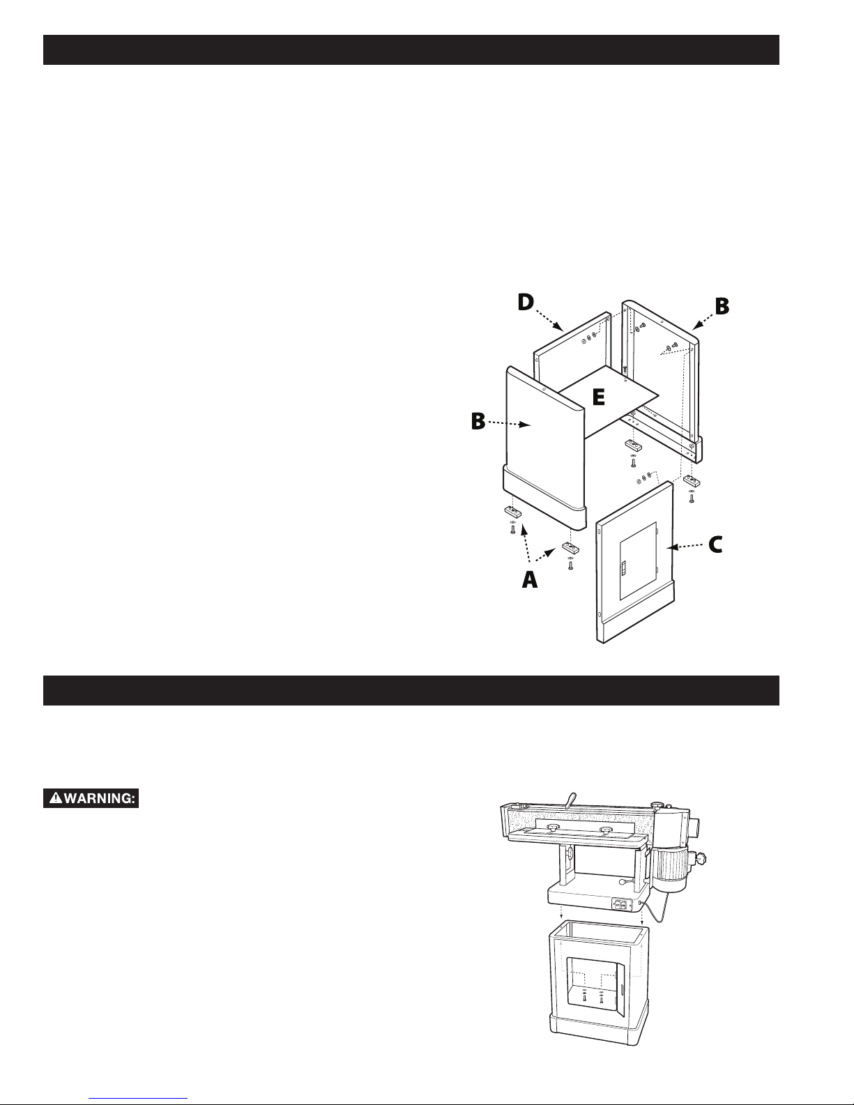
1. Referring to Fig. 2, attach the four rubber pads (A) to
the bottoms of the side panels (B) with four each 5/16”
x 5/8” screws, 5/16” flat washers and 5/16” hex nuts.
2. Use four 5/16” x 5/8” hex cap screws, eight 5/16” flat
washers, four 5/16” lock washers, and four 5/16” hex
nuts to attach the side panels (B) to the front panel (C).
Hand tighten only.
3. Attach the rear cabinet panel (D) to the side panels
using four 5/16” x 5/8” hex cap screws, eight 5/16” flat
washers, four 5/16” lock washers, and four 5/16” hex
nuts.
4. Turn cabinet right side up on a level surface and ensure
the top edges of all panels are flush.
5. Install the cabinet shelf (E) to the inside of the cabinet
using two M5x10 pan head screws, two M5 flat
washers and two M5 lock washers.
6. Tighten all hardware.
PARTS
• Rubber Feet (4)
• Side Cabinet Panels (2)
• Front Cabinet Panel with
Door (1)
• Rear Cabinet Panel (1)
• Cabinet Shelf (1))
HARDWARE NEEDED
• 5/16” x 5/8” screws (4)
• 5/16” flat washers (20)
• 5/16” hex nuts (12)
• 5/16” x 5/8” hex cap bolts (8)
• 5/16” lock washers (8)
• M5x10 pan head screws (2)
• M5 flat washers (2)
• M5 lock washers (2)
FIG. 2
MOUNTING THE TABLE ASSEMBLY TO THE CABINET
TOOLS REQUIRED
• 12 mm wrench
This step requires two adults. The table
assembly is heavy, be careful when
lifting it onto the stand! Failure to comply may cause
serious injury and/or damage to the sander and/or
property!
1. With the aid of another person, carefully lift the table
assembly onto the cabinet and position it so that the
two holes in the base of the table assembly align with
the holes located on either end of the cabinet. See
Fig. 3.
2. Open the cabinet door and, from inside the cabinet,
feed a 5/16” x 1-1/4” hex cap screw up through both
holes and secure using a 5/16” lock washer and 5/16”
flat washer. See Fig. 5.
3. Tighten hardware using a 12mm socket wrench.
PARTS
• Table Assembly
HARDWARE NEEDED
• 5/16” x 1-1/4” hex cap screws (2)
• 5/16” lock washers (2) 5/16” flat washers (2)
FIG.3
8
Page 9
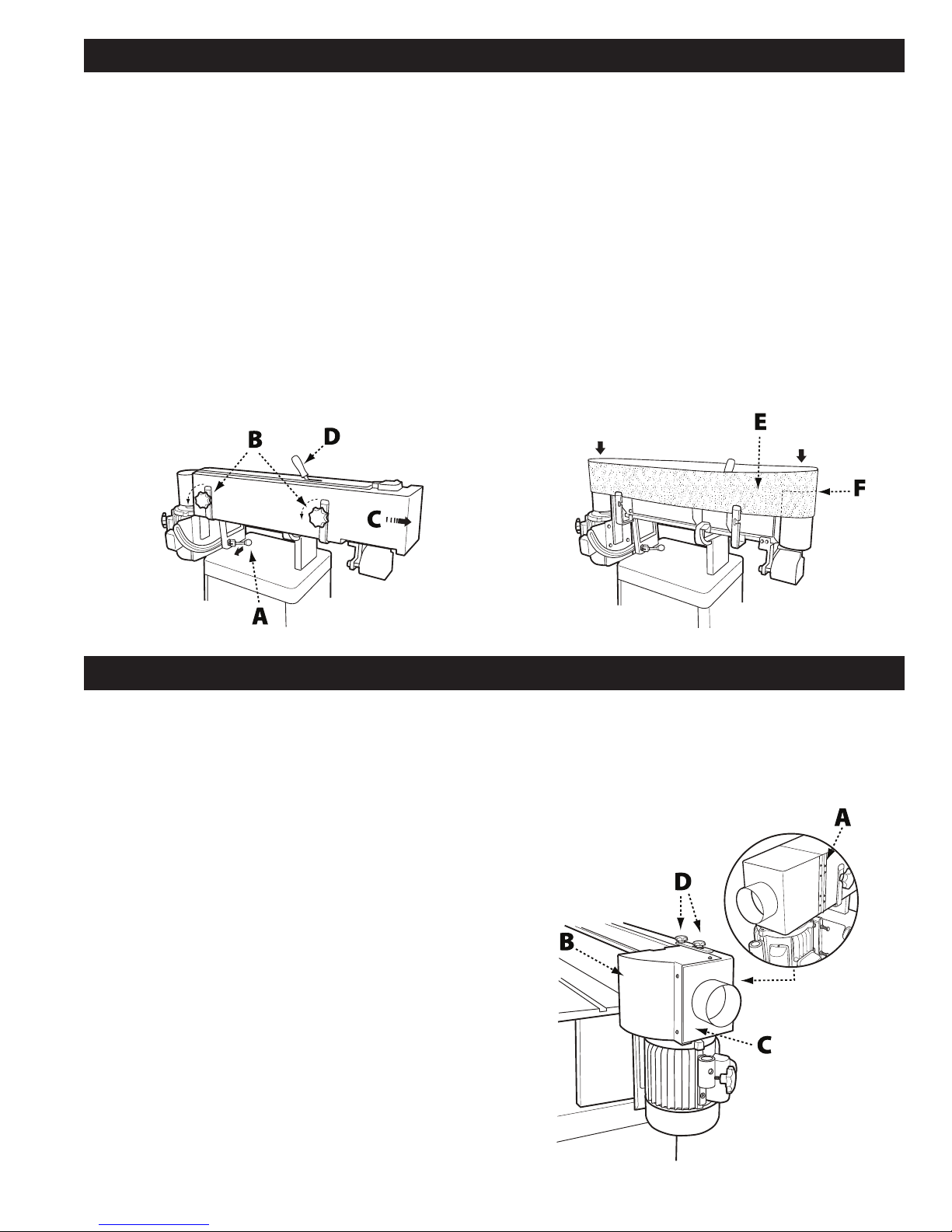
INSTALLING THE SANDING BELT
TOOLS REQUIRED
• Rubber Mallet
1. From the rear of the machine, unlock the sanding
platen assembly by pulling the lock handle(A)
toward you as indicated in Fig. 4. Rotate the
sanding platen assembly to the vertical position.
2. Push the lock handle back to its original position to
lock the platen assembly in place.
NOTE: Do not turn or rotate the lock handle as this will
change the tension of the locking assembly and make it
necessary for adjustment before using the tool.
3. Remove the belt guard by loosening the two lock
knobs (B) and sliding the belt guard to the right.
4. Place the handle (D) onto the belt tensioning lever
and gently tap into place using a rubber mallet.
PARTS
• 6” x 89” sanding belt
• Belt tensioning lever handle
HARDWARE NEEDED
• None
5. Move the lever in the direction indicated on the
label to release tension on the belt.
6. Fit the belt onto the sanding platen so that the
edge of the belt (E) is even with the edge of the
rollers (F) as shown in Fig. 5.
NOTE: Make sure that direction arrow on belt matches
the direction indicator on the top of the sanding
platen.
7. Return the belt tensioning lever to the Tight
position. Rotate the belt by hand in the direction
indicated by the arrow to ensure proper belt
tracking. If the belt tracking needs adjustment,
see Belt Tracking Adjustment on page 12.
FIG. 4
INSTALLING DRUM GUARD
TOOLS REQUIRED
• Phillips head screw driver
• Flat head screw driver
1. Attach one side of the hinge assembly (A) to the
rear belt guard using four Phillips head screws.
2. Place the drum guard (B) over the dust chute (C) as
shown in Fig. 6.
3. Secure the other side of the hinge to the drum
guard with the four remaining Phillips head screws.
4. Make sure the drum guard is in the closed position,
covering the drive belt.
NOTE: If the drum guard does not clear the motor case,
loosen the two lock knobs on the rear belt guard and
raise the rear belt guard slightly then retighten the lock
knobs.
5. Assemble one 12 mm flat washer on each of the
two 12mm lock knobs (D) and insert one lock knob
through the slot in the connection plate and the
other through the hole in the connection plate.
6. Tighten both knobs until secure.
To reposition the drum guard, loosen both lock knobs,
open or close the cover, then retighten the lock knobs.
PARTS
• Hinge
• Drum Guard
• 12mm Lock Knobs (2)
9
FIG. 5
HARDWARE NEEDED
• 8 Phillips head screws
• (size/type) washers (2)
FIG. 6
Page 10
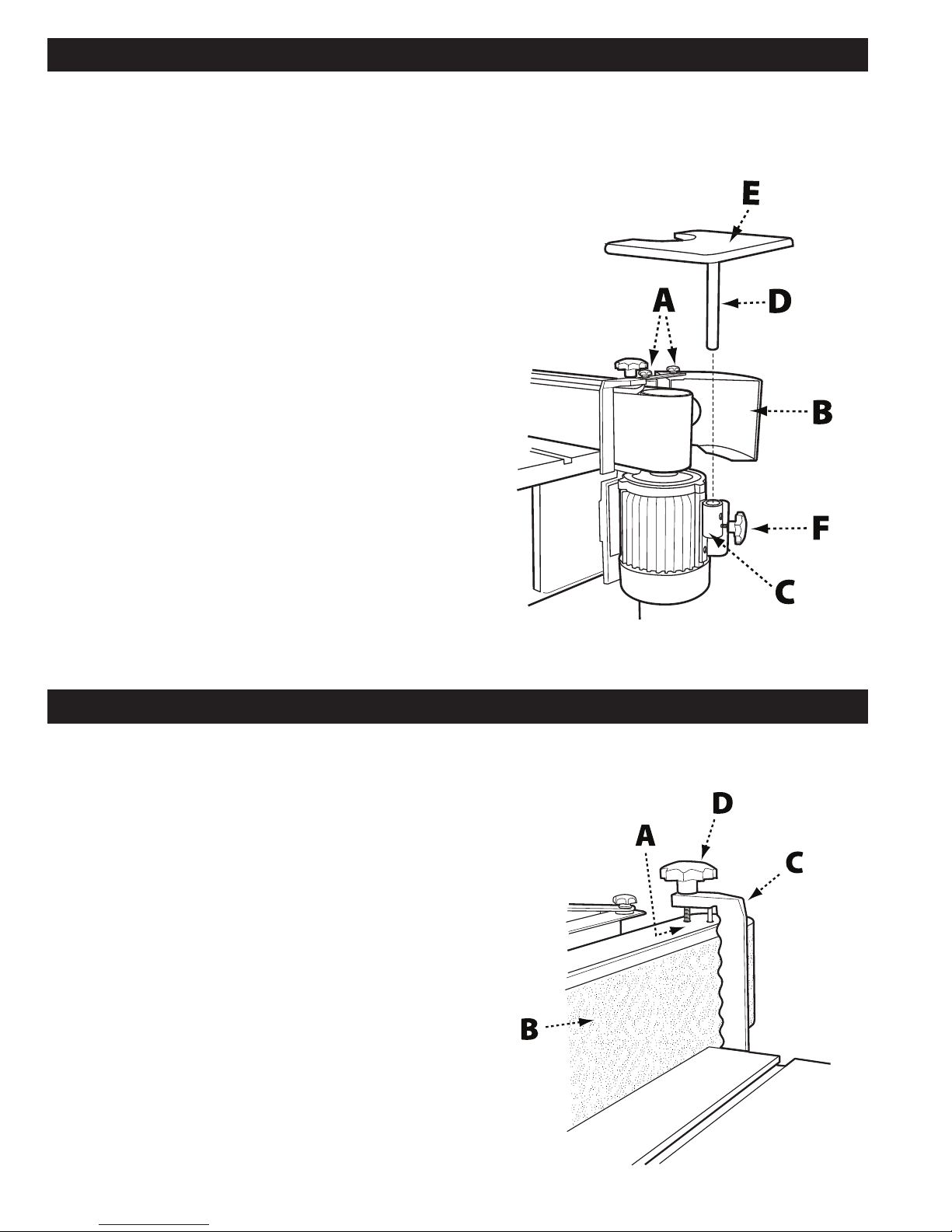
INSTALLING THE CONTOUR SANDING TABLE
TOOLS REQUIRED
• 12 mm socket wrench
1. Loosen the lock knobs (A) on the drum guard (B)
and rotate the drum guard back and out of the
way. Retighten the lock knobs.
2. Attach the mounting bracket (C) to the side of the
motor housing and secure using the two 10-24 x
3/4 socket head cap screws, as shown in Fig. 7.
The longer end of the mounted bracket should be
at the bottom.
3. Insert the mounting pole (D) into the contour
sanding table (E) and secure with 12mm hex cap
bolt and lock nut.
4. Insert the mounting pole/table assembly into the
mounting bracket. Ensure there is clearance on all
sides between the sanding belt and the contour
sanding table.
5. Secure the mounting pole/table assembly to the
mounting bracket using the (20mm) lock knob (F).
PARTS
• Contour Sanding Table
• Mounting Pole
• Mounting Bracket
• 20mm Lock Knob
HARDWARE NEEDED
• 10-24 x 3/4 Socket Head Cap Screws (2)
• 12mm Hex Cap Bolt
Important: When the contour sanding table is not in
use, the drum guard/dust port should always be in the
closed position so the drive drum is not in view.
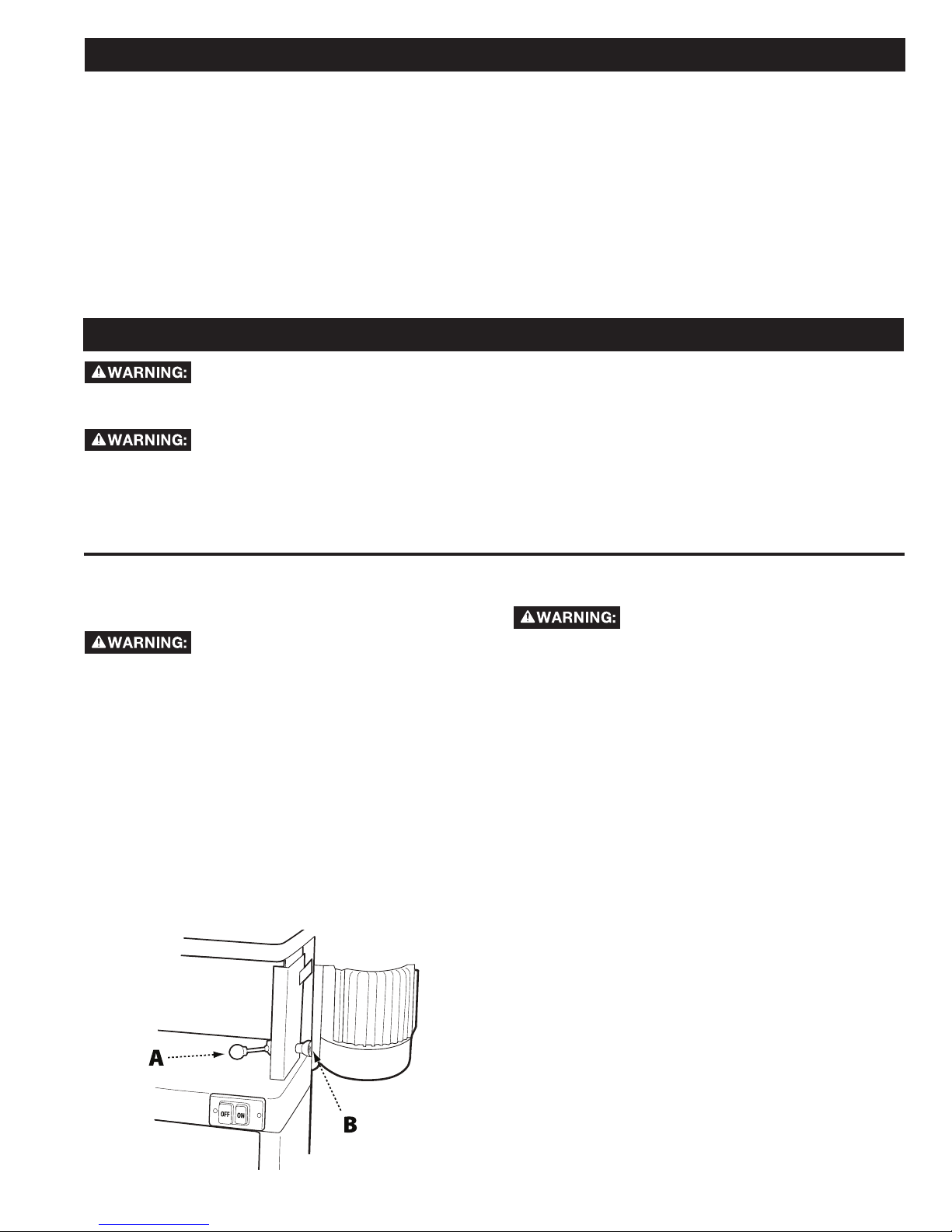
INSTALLING THE WORKPIECE SUPPORT
TOOLS REQUIRED
• None
1. Locate the two holes (A) on the right hand side of
the top of the sanding platen. See Fig. 8.
2. Insert the pin of the workpiece support (C) into the
hole closest to the front.
3. Secure the workpiece support to the sanding
platen by screwing the (35mm) lock knob (D) into
the tapped hole closest to the rear.
4. Ensure the workpiece support is as close to the
sanding belt (B) as possible without touching it.
5. Tighten the lock knob.
PARTS
• Workpiece Support
• (35mm) Lock Knob
FIG. 7
HARDWARE NEEDED
• None
FIG. 8
10
Page 11
INSTALLING THE SANDING FENCE
TOOLS REQUIRED
• None
1. Slide the two T-nuts into the slot located on the
sanding table.
2. Position the sanding fence so that one of the
t-nuts is aligned with one of the positioning slots.
3. Place a 5/16” flat washer onto a (12mm) lock knob
and thread the lock knob into the t-nut.
PARTS
• Sanding Fence
• Two (12mm) Lock Knobs
ADJUSTMENTS
Before making any adjustments to the tool, disconnect the machine from the power source.
TO ADJUST THE SANDING ANGLE
Before making any adjustments to the tool, disconnect the machine from the power source.
1. Loosen the platen locking lever by pulling forward.
2. Move the sanding platen to the desired position.
Use a combination square between the table and
sanding platen to get precise angles.
HARDWARE NEEDED
• T-Nuts (2)
• 5/16” Flat Washers (2)
4. Reposition the sanding fence so that the other
positioning slot is aligned with second t-nut.
5. Place a 5/16” flat washer onto the second (12mm)
lock knob and thread the lock knob into the
second t-nuts.
6. Position the fence to the desired distance from the
belt and securely tighten both lock knobs.
3. Hold the platen steady and push the platen locking
lever back to the locked position.
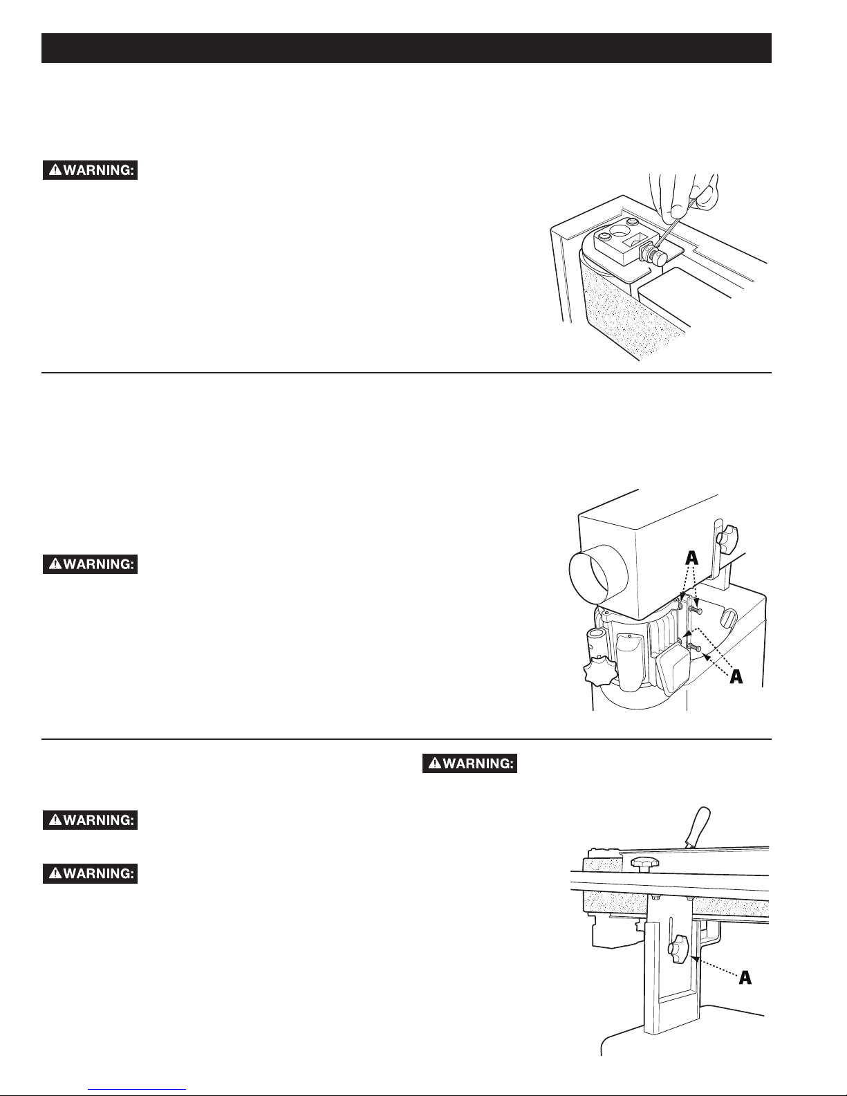
TO ADJUST THE TENSION ON
THE PLATEN LOCKING LEVER
Before making any adjustments to the
tool, disconnect the machine from the
power source.
1. Loosen the platen locking lever (A) and rotate the
platen into the horizontal (flat) position. Do not lock.
2. Adjust tension on the eccentric block by tightening
the nylon nut (B) with a 14mm wrench. See Fig. 9.
Turn the nut in ¼-turn increments and test locking
handle for proper tension.
3. The platen locking lever is properly tensioned when
it requires positive force to move the eccentric
block from one side to the other.
4. Ensure the platen and motor assembly remains
stationary when the platen locking lever is in the
locked position. Re-adjust as necessary.
TO CHANGE THE SANDING BELT
Before making any adjustments to the
tool, disconnect the machine from the
power source.
1. Ensure the sanding platen is locked in the vertical
(upright) position. Reposition if needed. (Refer to
Adjusting the Sanding Angle at the top pf this page).
2. Remove the belt guard by loosening the two lock
knobs and sliding the belt guard to the right.
3. Release tension on the belt by moving the belt
tensioning lever to the Loose position as indicated
on the label on top of the guard.
4. Remove the old belt by working it up and over the
rollers.
5. Fit the new belt onto the sanding platen. Note:
Make sure that direction arrow on belt matches the
direction indicator on the top of the sanding platen.
The edge of the belt should be even with the edge
of the rollers.
6. Re-tension the belt by moving the belt tensioning
lever to the Tight position.
7. Rotate the belt by hand in the direction indicated
by the arrow to ensure proper belt tracking. Note:
Belts stretch with wear. When replacing a belt, you
may have to adjust tracking. See Belt Tracking
Adjustment on page 12.
8. Reinstall the belt guard and tighten the lock
handles.
FIG. 9
11
Page 12
ADJUSTMENTS
TO ADJUST THE BELT
TRACKING
Tools Needed: Belt Tracking Tool (provided)
Before making any adjustments to the
tool, disconnect the machine from the
power source.
1. Rotate the belt by hand from left to right and
observe whether the belt is tracking above or below
the edges of the rollers.
2. Using the belt tracking tool (provided) loosen the
micro adjust lock nut.
3. Based on whether the belt is tracking up or
down, turn the micro adjusting screw in 1/4 – turn
increments to the left or right until the belt tracks
MOTOR MOUNT TRACKING
ADJUSTMENT
Tools Needed: Two 1/2" Wrenches
Note: The Motor Mount Tracking Adjustment is a
course adjustment. Use the Belt Tracking Adjustment
first for fine adjustment. If it cannot be adjusted, then
use the procedure described below.
Before making any adjustments to the tool, disconnect
the machine from the power source.
1. Loosen the four motor mount
nuts (A) just enough so the tracking
screws can be turned to make an adjustment. See
Fig. 11.
2. Loosen the two locking hex nuts that secure the
tracking screws.
3. Turn one screw a 1/4-turn and rotate the sanding
belt by hand to observe which direction the
adjustment is causing the belt to move. If it is
evenly on the rollers when rotated by hand. See
Fig. 10.
4. Re-tighten the micro adjusting nut.
NOTE: The Belt Tracking Adjustment provides a minor
adjustment that
should correct
most tracking
problems. If
the tracking
problem persists,
use the Motor
Mount Tracking
Adjustment (next
section).
FIG. 10
traveling in the direction needed to correct the
problem, go to step 5.
4. If the belt tracks in the wrong direction, back off
a 1/4-turn and tighten the other screw a quarter
turn. This should start the belt moving in the proper
direction.
5. Tighten both
locking nuts and
motor mount
nuts.
6. Return to the
Belt Tracking
Adjustment
section (previous
page) to fine tune
the tracking.
FIG. 11
TO ADJUST THE SANDING
TABLE HEIGHT
Before making any adjustments to the
tool, disconnect the machine from the
power source.
Never position the sanding table below
the sanding belt! Keep an overlap
of at least 1/16” between table and sanding belt to
avoid material and/or fingers getting caught! Failure to
comply may cause serious injury!
1. There are two height elevation lock knobs (A) one
on either side of the table support, shown in Fig. 12.
Loosen both lock knobs just enough to allow the
sanding table to move up and down.
The table is very heavy. Loosen lock
knobs slowly and just enough to create
play in table Failure to comply may cause serious injury!
2. Raise or lower
work table to
desired level.
3. Tighten the
lock knobs.
FIG. 12
12
Page 13

MAINTENANCE PROCEDURES
Your Oscillating Edge Sander requires little
maintenance beyond the routine inspection,
lubrication, and cleaning.
ROUTINE INSPECTION
It is a good idea to routinely inspect any quality
woodworking tool in order to keep it in optimum
condition. This includes inspecting all hardware for
tightness, ensuring drive belts are in good condition,
and cleaning debris and grime from any surfaces and
moving parts.
LUBRICATION
The sealed motor of your Oscillating Edge Sander
is maintenance-free. However, it is recommended
that you periodically lubricate the gears in the gear
box using a quality #2 grease or equivalent. To keep
the sander table and other bare metal parts in good
working condition, apply an occasional coat of quality
paste wax, free of silicone or synthetics
CLEANING THE SANDING BELT
Regularly inspect and, if necessary, clean the sanding
belt with a high quality gum rubber belt cleaner. If you
notice sanding performance is significantly decreasing,
it may be time to replace the sanding belt. Refer to
directions on page 11.
TROUBLESHOOTING GUIDE
TROUBLE POSSIBLE CAUSE
1. Sander unplugged from wall or motor
Sander will not start
Sanding belt does
not come up to
speed
Machine vibrates
excessively
Abrasive belt keeps
tearing
Sanded edge not
square
2. Fuse blown or circuit breaker tripped
3. Cord damaged
1. Extension cord too light or too long
2. Motor not wired for proper voltage
3. Low current
1. Stand on uneven floor
2. Motor mounts are loose
3. Tension spring is worn or broken
1. Belt is running in the wrong direction
1. Table not square to sanding platen 1. Use a square to adjust table to sanding platen
SOLUTION
1. Check all plug connections
2. Replace fuse or reset circuit breaker
3. Replace cord
1. Replace with adequate size and length cord
(see Recommended Extension Cord Gauges
on page 6)
2. Refer to motor junction cover for proper wiring
3. Contact a qualified electrician
1. Adjust stand so that it rests evenly on the floor
2. Tighten motor mount bolts
3. Replace spring
1. Arrow on the sanding belt and machine
should be pointing in the same direction.
Sanding marks on
wood
1. Wrong grit sanding belt
2. Feed pressure too great
3. Sanding against the grain
1. Use coarser grit for stock removal and fine grit
for finish sanding.
2. Never force work into sanding platen
3. Sand with the grain
13
Page 14

ACCESSORIES
A complete line of accessories is available from your DELTA® Supplier, DELTA® Factory Service Centers, and
DELTA® Factory Service Centers, and DELTA® Authorized Service Centers. Please visit our Web Site www.
DeltaMachinery.com for an online catalog or for the name or your nearest supplier.
Since accessories other than those offered by DELTA® have not been tested with this product,
use of such accessories could be hazardous. For safest operation, only DELTA® recommended
accessories should be used with this product.
PARTS, SERVICE OR WARRANTY ASSISTANCE
All DELTA® Machines and accessories are manufactured to high quality standards and are serviced by a network of
DELTA® Factory Service Centers and DELTA® Authorized Service Centers. To obtain additional information regarding
your DELTA® quality product or to obtain parts, service, warranty assistance, or the location of the nearest service
center, please call 1-800-223-7278.
WARRANTY
To register your tool for warranty service visit our website at www.DeltaMachinery.com.
Five Year Limited New Product Warranty
DELTA® will repair or replace, at its expense and at its option, any new DELTA® machine, machine part, or machine accessory which in normal
use has proven to be defective in workmanship or material, provided that the customer returns the product prepaid to a DELTA
center or authorized service station with proof of purchase of the product within five years and provides DELTA
to verify the alleged defect by inspection. For all refurbished DELTA
for any asserted defect which has resulted from normal wear, misuse, abuse or repair or alteration made or specifically authorized by anyone
other than an authorized DELTA
damages resulting from defective products. Some states do not allow the exclusion or limitation of incidental or consequential damages, so
the above limitation or exclusion may not apply to you. This warranty is DELTA
with respect to defective products; all other warranties, express or implied, whether of merchantability, fitness for purpose, or otherwise, are
expressly disclaimed by DELTA
1-800-223-7278. This warranty gives you specific legal rights and you may have other rights which vary in certain states or provinces.
LATIN AMERICA: This warranty does not apply to products sold in Latin America. For products sold in Latin America,
see country specific warranty information contained in the packaging, call the local company or see website for warranty
information.
®
service facility or representative. Under no circumstances will DELTA® be liable for incidental or consequential
®
. For further detail of warranty coverage and warranty repair information, visit www.DeltaMachinery.com or call
®
product, the warranty period is 180 days. DELTA® will not be responsible
®
’s sole warranty and sets forth the customer’s exclusive remedy,
®
with reasonable opportunity
®
factory service
14
Page 15

REPLACEMENT PARTS
Use only identical replacement parts. For a parts list or to order parts, visit our website at www.DeltaMachinery.com/service. You can
also order parts from your nearest factory-owned branch, Authorized Warranty Service Center or by calling Technical Service Manager at
1-800-223-7278 to receive personalized support from one of our highly-trained representatives.
FREE WARNING LABEL REPLACEMENT
If your warning labels become illegible or are missing, call
1-800-223-7278
for a free replacement.
Warning
For Your Own Safety, Read Instructions
Manual Before Operafting Sander
1. Wear eye protection
2. Suport work piece with backstop or
work table
3. Maintain 1/16 inch maximum clearance
between table and sanding belt.
SERVICE AND REPAIRS
All quality tools will eventually require servicing and/or replacement of parts. For information
about DELTA® Power Equipment Corporation, its factory-owned branches, or to locate an
Authorized Warranty Service Center, visit our website at www.DeltaMachinery.com/service
or call our Customer Care Center at 1-800-223-7278. All repairs made by our service centers are fully
guaranteed against defective material and workmanship. We cannot guarantee repairs made or attempted by
others. By calling this number you can also find answers to most frequently asked questions 24 hours/day.
You can also write to us for information at DE LTA
Jackson, TN 38305 - Attention: Technical Service Manager. Be sure to include all of the information shown
on the nameplate of your tool (model number, type, serial number, date code, etc.)
®
Power Equipment Corporation, 4825 Highway 45 North,
15
Page 16

IMPORTANTES CONSIGNES DE SÉCURITÉ
ASSUREZ-VOUS D’AVOIR BIEN LU ET COMPRIS TOUTES LES MISES EN
GARDE ET LES CONSIGNES D’UTILISATION AVANT D’UTILISER CET
ÉQUIPEMENT. Le fait de ne pas respecter toutes les instructions ci-dessous,
peut avoir pour conséquence : choc électrique, incendie et/ou blessures graves ou dégâts matériels.
Le travail du bois peut être dangereux si des procédures d’utilisation sécuritaires et adéquates ne sont pas
respectées. Comme c’est le cas pour toute pièce de machinerie, certains dangers sont assortis à l’utilisation de
ce produit. En utilisant cet appareil selon les directives et avec prudence, vous réduirez grandement la possibilité
de blessures. Cependant, si les précautions normales de sécurité sont négligées ou ignorées, la personne utilisant
l’appareil pourra être blessée. L’équipement de sécurité comme les dispositifs de protection, bâtons poussoir,
dispositif de retenue à ressort, cales-guide, lunettes, masques anti-poussière et protecteurs d’oreilles peut réduire
les risques de blessures. Mais même les dispositifs de protection les plus efficaces ne pourront vous protéger
contre un manque de jugement, de soin ou d’attention. Utilisez toujours votre bon sens et faites preuve de prudence
dans l’atelier. Si une manœuvre vous semble dangereuse, ne la tentez pas. Essayez plutôt de trouver une autre
solution qui vous paraît plus sûre. RAPPELEZ-VOUS : Vous êtes responsable de votre propre sécurité. Pour des
renseignements complémentaires, rendez-vous sur notre site web à l’adresse www.DeltaMachinery.com.
Cet appareil a été conçu seulement pour certains types d’utilisation. DELTA® Power
Equipment Corporation recommande fortement que cet appareil ne soit ni modifié ni utilisé à
toute autre fin que celles pour lesquelles il a été conçu. Si vous avez des questions sur un type d’utilisation en
particulier, N’UTILISEZ PAS l’appareil avant d’avoir d’abord contacté DELTA® pour déterminer si elle peut ou si elle
devrait être réalisée avec ce produit.
Si vous avez des questions sur son utilisation, N’UTILISEZ PAS le produit tant que vous n’avez pas écrit à
DELTA® Power Equipment Corporation et obtenu une réponse de leur part. Contactez-nous en ligne sur www.
DeltaMachinery.com ou par courrier à l’adresse suivante : responsable du service technique, DELTA® Power
Equipment Corporation, 4825 Highway 45 North, Jackson, TN 38305.
• Les informations concernant l’utilisation sûre et correcte de cet outil sont disponibles auprès des sources suivantes :
• Power Tool Institute, 1300 Sumner Avenue, Cleveland, OH 44115-2851 ou en ligne sur HYPERLINK http://www.
powertoolinstitute.com/ www.powertoolinstitute.com
• National Safety Council, 1121 Spring Lake Drive, Itasca, IL 60143-3201
• American National Standards Institute, 25 West 43rd Street, 4 floor, New York, NY 10036 HYPERLINK http://www.
ansi.org/ www.ansi.org - ANSI 01.1 Exigences de sécurité pour machines à bois
• U.S. Department of Labor regulations www.osha.gov
CONSIGNES DE SÉCURITÉ - DÉFINITIONS
Ce manuel contient des informations qu’il est important de connaître et de comprendre. Ces informations ont pour
but d’assurer VOTRE SÉCURITÉ et de PRÉVENIR LES PROBLÈMES D’ÉQUIPEMENT. Pour vous aider à reconnaître
ces informations, nous utilisons les symboles ci-dessous. Veuillez lire le manuel et prêter attention à ces sections-là.
indique une situation dangereuse imminente qui, si elle n’est pas évitée, provoquera la mort ou une
blessure grave.
indique une situation dangereuse potentielle qui, si elle n’est pas évitée, provoquera la mort
ou une blessure grave.
indique une situation dangereuse potentielle qui, si elle n’est pas évitée, peut provoquer une
blessure mineure ou modérée.
utilisé sans le symbole d’alerte de sécurité indique une situation potentiellement dangereuse qui,
si elle n’est pas évitée, peut entraîner des dommages matériels.
FRANÇAIS
16
Page 17

RÈGLES DE SÉCURITÉ GÉNÉRALES
LE NON-RESPECT DE CES RÈGLES RISQUE D’ENTRAÎNER DES BLESSURES GRAVES.
POUR VOTRE PROPRE SÉCURITÉ, LISEZ ET COMPRENEZ BIEN LE MANUEL D’UTILISATION AVANT DE
•
FAIRE FONCTIONNER L’APPAREIL.
rattachés.
GARDEZ LA ZONE DE TRAVAIL PROPRE.
•
N’UTILISEZ PAS CET APPAREIL DANS UN ENVIRONNEMENT DANGEREUX.
•
endroit humide ou mouillé, et ne l’exposez pas à la pluie. Gardez votre lieu de travail bien éclairé.
MAINTENEZ LES ENFANTS ET LES VISITEURS À L’ÉCART.
•
distance sécuritaire de l’aire de travail.
DÉBRANCHEZ L’APPAREIL
•
VÉRIFIEZ LES PIEZAS ENDOMMAGÉES.
•
endommagée.
LE NON-RESPECT DE CES RÈGLES PEUT ENTRAÎNER DES BLESSURES GRAVES.
avant toute opération d’entretien.
Apprenez à connaître son utilité et ses limites, ainsi que les dangers qui lui sont
Les aires et bancs de travail encombrés attirent les accidents.
N’utilisez pas cet appareil dans un
Tous les enfants et visiteurs doivent demeurer à une
Avant d’utiliser l’appareil, réparez ou remplacez toute partie
1. Lisez et comprenez les avertissements affichés sur
l’appareil et dans ce manuel. Ne pas se conformer
à tous ces avertissements peut entraîner des
blessures graves.
2. Remplacez les étiquettes d’avertissement si elles
sont masquées ou supprimées.
3. Cette ponceuse oscillante pour champs est conçue
et destinée pour être utilisée par un personnel
dûment formé et expérimenté seulement. Si vous
n’êtes pas habitué avec le fonctionnement adéquat
et sécuritaire d’une ponceuse oscillante pour
champs, évitez de l’utiliser avant d’avoir reçu la
formation et acquis les connaissances appropriées.
4. N’utilisez pas cet appareil à toute autre fin que
l’usage prévu. Autrement, Delta Power Equipment
Company, Inc. décline toute garantie réelle ou
implicite et se dégage de toute responsabilité
pour toute blessure qui pourrait résulter de cette
utilisation.
5. Portez toujours des lunettes de protection ou des
écrans faciaux approuvés pendant l’utilisation de
cette ponceuse oscillante pour champs.
6. Avant d’utiliser cette ponceuse oscillante pour
champs, enlevez cravate, bagues, montres et
autres bijoux et retroussez vos manches au-dessus
du coude. Retirez tous les vêtements amples et
retenez les cheveux longs. Il est recommandé de
porter des chaussures antidérapantes ou de poser
des bandes de plancher antidérapantes. Ne portez
pas de gants.
7. Portez des protecteurs pour l’ouïe (bouchons
ou manchons) pendant les longues périodes de
fonctionnement.
8. Certaines poussières produites par les activités de
ponçage, de sciage, de meulage, de perçage ainsi
que d’autres activités de construction peuvent
contenir des produits chimiques pouvant causer
le cancer, des anomalies congénitales ou d’autres
problèmes liés aux fonctions reproductrices. En
voici des exemples :
• Plomb de peintures à base de plomb;
• Silice cristalline de briques, de ciment et d’autres
produits de maçonnerie;
• Arsenic et chrome de bois de sciage traité
chimiquement.
Votre risque à ces expositions varie, selon la
fréquence à laquelle vous effectuez ce genre
d’activité. Pour réduire l’exposition à ces produits
chimiques, travaillez dans un endroit bien ventilé et
avec de l’équipement de protection approuvé, comme
les masques antipoussières spécialement conçus pour
filtrer les particules microscopiques
1. N’utilisez pas cet appareil en état de fatigue ou avec
les facultés affaiblies par la drogue, l’alcool ou les
médicaments.
2. Avant de brancher l’appareil sur la source
d’alimentation, assurez-vous que l’interrupteur est
en position « OFF » (Arrêt).
3. Assurez-vous que la machine est correctement
mise à la terre.
4. Faites les réglages de la machine ou son entretien
seulement lorsque celle-ci est débranchée de la
source d’alimentation.
5. Prenez l’habitude de vérifier que tout l’équipement
supplémentaire tel que les clés de réglage, les clés
à molette, la ferraille, le matériel et les chiffons de
nettoyage a été éloigné de la machine avant de la
mettre en marche.
6. Gardez les dispositifs de protection en place en tout
temps lorsque l’appareil est utilisé. Faites preuve
d’une extrême prudence s’ils sont enlevés à des
fins d’entretien et remettez-les en place dès la fin de
l’entretien.
7. Assurez-vous que la ponceuse oscillante pour
champs est solidement fixée au plancher avant de
l’utiliser.
8. Vérifiez s’il y a des pièces endommagées. Avant
d’utiliser l’appareil, il faut vérifier soigneusement
17
Page 18

le dispositif de protection ou toute autre partie
endommagée afin de s’assurer qu’ils fonctionnent
correctement et rempliront leur fonction prévue.
Vérifiez l’alignement des pièces mobiles et
leurs joints, tout bris de pièce et du cadrage et
toute autre condition qui pourrait en modifier le
fonctionnement. Un dispositif de protection
endommagé, ou toute autre pièce endommagée
doit être réparé et remplacé adéquatement.
9. Prévoyez un espace suffisant autour de la zone de
travail et un éclairage en plongée non éblouissant.
10. Gardez le plancher autour de l’appareil propre et
exempt de débris, d’huile et de graisse.
11. Gardez les visiteurs à une distance sécuritaire de la
zone de travail. Tenez les enfants à distance.
12. Rendez votre atelier à l’épreuve des enfants au
moyen de cadenas, de commutateurs principaux
ou en retirant les clés de mise en marche.
13. Concentrez-vous uniquement sur votre travail.
Regarder aux alentours, tenir une conversation
et faire du chahut sont des actes négligents qui
peuvent entraîner des blessures graves.
14. Maintenez une posture équilibrée en tout temps
pour éviter de tomber ou de vous appuyer contre
la courroie de ponçage ou d’autres pièces mobiles.
Évitez de vous étirer ou d’utiliser une force
excessive pour effectuer toute opération avec
l’appareil.
15. Utilisez l’outil approprié à la bonne vitesse et au
bon débit d’alimentation. Ne forcez pas un outil ou
un accessoire à effectuer une tâche pour laquelle il
n’a pas été conçu. Le bon outil fera mieux le travail
et sera plus sécuritaire.
16. Utilisez les accessoires recommandés; les
accessoires inadéquats peuvent être dangereux.
17. Entretenez les appareils avec soin. Suivez les
indications pour le graissage et le changement
d’accessoires.
18. Débranchez l’appareil avant le nettoyage. Utilisez
une brosse ou de l’air comprimé pour enlever la
poussière ou des débris; n’utilisez pas vos mains.
19. Ne vous tenez pas debout sur l’appareil. Des
blessures graves pourraient se produire si l’appareil
se renverse.
20. Ne laissez jamais l’appareil en marche sans
surveillance. Débranchez l’appareil et ne le laissez
pas sans surveillance jusqu’à son arrêt complet.
21. Tenez la poignée fermement en tout temps.
22. N’utilisez pas cette ponceuse pour d’autres fins
que celles pour lesquelles elle est prévue. Si elle
est utilisée à d’autres fins, Delta Power Equipment
Company, Inc. décline toute garantie réelle ou
implicite et se dégage de toute responsabilité
pour toute blessure qui pourrait résulter de cette
utilisation.
CONSERVER CES CONSIGNES.
Consultez-les souvent et utilisez-les pour enseigner aux autres.
18
Page 19

BRANCHEMENTS
Il faut utiliser un circuit électrique séparé pour vos appareils. Les fils du circuit doivent avoir un calibre d’au moins
12 et être protégés par un fusible à action différée de 20 ampères. Si vous utilisez une rallonge, ne prenez que des
rallonges à 3 fils avec fiche de mise à la terre à 3 branches et un réceptacle correspondant qui acceptera la prise de
l’appareil. Avant de brancher l’appareil à la ligne électrique, assurez-vous que le ou les interrupteurs sont en position
« OFF » (Arrêt) et que le courant électrique a les mêmes caractéristiques que celui indiqué sur l’appareil. Toutes les
connexions électriques doivent établir un bon contact. Une utilisation à basse tension endommagera l’appareil.
N’UTILISEZ PAS L’APPAREIL DANS UN ENDROIT HUMIDE OU MOUILLÉ, ET NE L’EXPOSEZ
PAS À LA PLUIE.
SPÉCIFICATIONS DU MOTEUR
L’appareil est conçu pour être alimenté par un courant alternatif de 120/240 volts et 60 Hz. Avant de brancher
l’appareil à la source d’alimentation, assurez-vous que l’interrupteur est en position « OFF » (Arrêt).
DIRECTIVES DE MISE À LA TERRE
CET APPAREIL DOIT ÊTRE MIS À LA TERRE LORSQU’IL EST EN MARCHE POUR PROTÉGER
CELUI QUI LE MANIPULE D’UNE DÉCHARGE ÉLECTRIQUE.
1. Pour tous les appareils branchés avec un cordon d’alimentation et mis à la terre :
En cas de mauvais fonctionnement ou d’une panne, la mise à la terre fournit un chemin de moindre résistance au
courant pour réduire le risque de décharge électrique. Cet appareil est équipé d’un cordon électrique possédant
un conducteur de terre et une fiche de terre. La fiche doit être branchée sur une prise correspondante qui a été
correctement installée et mise à la terre conformément à tous les codes et règlements locaux.
Ne pas modifier la fiche fournie; si elle n’entre pas dans la prise, faites installer une prise adéquate par un électricien
qualifié.
Un branchement incorrect du conducteur pour la mise à la terre peut entraîner un risque de décharge électrique.
Le fil conducteur avec un isolant comportant une surface extérieure verte, avec ou sans rayures jaunes, est le
conducteur de terre. S’il faut remplacer ou réparer le cordon électrique ou la fiche, ne branchez pas le conducteur de
terre à une borne sous tension.
Si les instructions de mise à la terre ne sont pas complètement comprises, ou si vous doutez que l’appareil soit
correctement relié à la terre, vérifiez avec un électricien qualifié ou le personnel de service.
Utilisez uniquement des rallonges à 3 fils avec fiche de mise à la terre à 3 branches et des réceptacles
correspondants qui accepteront la prise de l’appareil, telles qu’illustrées à la Fig. A.
Réparez ou remplacez immédiatement un cordon abîmé ou usé.
2. Pour les machines mises à la terre et branchées à un cordon d’alimentation utilisées sur un circuit
d’alimentation de régime nominal inférieur à 150 volts :
Si l’appareil est utilisé sur un circuit dont la prise de courant ressemble à celle illustrée à la Fig. A, la machine aura
alors une fiche de mise à la terre semblable à celle illustrée à la Fig. A. Un adaptateur temporaire, qui ressemble à
celui illustré à la Fig. B, peut être utilisé pour brancher cette fiche à un réceptacle à 2 conducteurs correspondant,
comme l’illustre la Fig. B, s’il n’existe aucune prise de courant correctement mise à la terre. Vous pouvez utiliser
un adaptateur temporaire seulement jusqu’à ce qu’une prise correctement mise à la terre puisse être installée par
un électricien qualifié. La patte rigide verte, la cosse et tout élément semblable sortant de l’adaptateur doivent
être correctement branchés à une masse permanente comme une boîte de sortie mise à la terre. Chaque fois que
l’adaptateur est utilisé, il doit être maintenu en place par une vis métallique.
REMARQUE : Au Canada, le Code électrique canadien n’autorise pas l’utilisation d’un adaptateur temporaire.
DANS TOUS LES CAS, ASSUREZ-VOUS QUE LE RÉCEPTACLE EN QUESTION EST BIEN MIS À
LA TERRE. EN CAS DE DOUTE, DEMANDER À UN ÉLECTRICIEN PROFESSIONNEL DE
VÉRIFIER LA PRISE.
PRISE DE
TERRE
FICHES
CONDUCTRICES DE
COURANT
FICHE DE MISE À
LA TERRE EST LA PLUS LONGUE DES 3 FICHES
FIG. A FIG. B
BOÎTE DE PRISE DE TERRE
BORNIERS
MOYENS
ADAPTATEUR
19
Page 20

3. Fonctionnement monophasé à 240 volts
Le moteur fourni avec la machine est un moteur bitension de 120/240 volts. Il est livré, prêt à fonctionner, sous
tension de 120 volts. Toutefois, il peut être converti au fonctionnement sous tension de 240 volts.
Faire appel à un électricien qualifié pour effectuer la conversion ou aux services d’un centre de réparation agréé
Delta. Une fois la conversion effectuée, l’appareil doit être conforme au Code électrique national et à tous les codes
et règlements locaux.
La conversion de l’appareil requiert un recâblage du moteur pour 240 volts, avec l’installation d’une fiche
de 240 volts au cordon d’alimentation et le remplacement de l’interrupteur par un autre homologué pour un
fonctionnement à 240 volts. Assurez-vous que la fiche de 240 volts s’insère seulement dans une prise ayant la même
configuration que la fiche illustrée à la Fig. C. Aucun adaptateur ne devrait être utilisé avec la fiche de 240 volts
BOÎTE DE SORTIE MISE À LA TERRE
BROCHES
CONDUCTRICES
question est bien mis à la terre. Si vous n’êtes pas
Dans tous les cas, assurezvous que le réceptacle en
certain, faites vérifier le réceptacle par un électricien
qualifié.
AUGE MINIMUM POUR CORDON PROLONGATEUR
CALIBRES RECOMMANDÉS POUR UNE UTILISATION AVEC DES APPAREILS ÉLECTRIQUES STATIONNAIRES
LA LAME DE MISE À LA TERRE
EST LA PLUS LONGUE DES
TROIS LAMES
FIG. C
RALLONGES
MISE EN GARDE-Utilisez des
rallonges adéquates. Assurezvous que la rallonge a 3 fils, est en bon état et est
munie d’une fiche de mise à la terre à 3 branches et
un réceptacle correspondant qui acceptera la prise de
l’appareil. Lorsque vous utilisez une rallonge, assurezvous qu’elle est suffisamment puissante pour prendre
en charge le courant de l’appareil. Un cordon sousdimensionné provoquera une chute de tension de ligne
causant une perte de courant et à une surchauffe. La
figure D illustre le bon calibre à utiliser selon la longueur
de la rallonge. Dans le doute, utilisez le prochain calibre
le plus élevé. Plus le numéro du calibre est petit, plus
lourde sera la rallonge.
Ampérage
Service
Nominal
0 À 6
0 À 6
0 À 6
0 À 6
6 À 10
6 À 10
6 À 10
6 À 10
10 À 12
10 À 12
10 À 12
10 À 12
12 À 16
12 À 16
12 À 16
Volts Longueur Totale Du Cordon
120
120
120
50 À 100 (15,24 À 30,48 M)
120
100 À 150 (30,48 À 45,72 M)
120
120
120
50 À 100 (15,24 À 30,48 M)
120
100 À 150 (30,48 À 45,72 M)
120
120
120
50 À 100 (15,24 À 30,48 M)
120
100 À 150 (30,48 À 45,72 M)
120
120
120
En Pieds
JUSQU’À 25 (7,62 M)
25 À 50 (7,62 À 15,24 M)
JUSQU’À 25 (7,62 M)
25 À 50 (7,62 À 15,24 M)
JUSQU’À 25 (7,62 M)
25 À 50 (7,62 À 15,24 M)
JUSQU’À 25 (7,62 M)
25 À 50 (7,62 À 15,24 M)
LES RALLONGES DE PLUS DE 50 PIEDS (15,24 M) NE SONT PAS
RECOMMANDÉES
FIG. D
Jauge Des Fils
Électriques De
La Rallonge
18 AWG
16 AWG
16 AWG
14 AWG
18 AWG
16 AWG
14 AWG
12 AWG
16 AWG
16 AWG
14 AWG
12 AWG
14 AWG
12 AWG
CARACTÉRISTIQUES ET COMPOSANTES IMPORTANTES
1- Goulotte à poussière
2- Courroie de ponçage
3- Armoire
4- Interrupteur d’alimentation
5- Verrouillage de patin
6- Barrière du support
7- Levier de tension de la courroie
8- Table de ponçage pour contour
9 - Moteur à induction de 1 1/2 HP
10 - Support de pièce
11- Protège-courroie arrière
FIG. 1
20
Page 21

DESCRIPTION DU FONCTIONNEMENT
La ponceuse oscillante pour champs DELTAMD est un outil de calibre professionnel conçu pour le ponçage des
surfaces droites et à angle ainsi que pour le ponçage de contour. Elle peut poncer en plan vertical ou horizontal. La
ponceuse oscillante DELTAMD est accompagnée d’une courroie de ponçage de calibre 100 grains et est montée sur
une base d’une armoire qui procure un ample espace de rangement pour les accessoires. Cet outil est alimenté par
un moteur à induction de 1 1/2 HP et de 120/240 V qui fait fonctionner la courroie de ponçage en un va-et-vient de
1,27 cm à un débit de 108 coups la minute.
SPÉCIFICATIONS DU PRODUIT
Modèle 31-482
Barrière (h x L) 10,16 cm x 60,96 cm
Taille de la courroie de ponçage (l x h) 15,24 cm x 226,06 cm
Diamètre de la goulotte à poussière 10,16 cm
Taille de la table de ponçage pour contour 24,77 cm x 29,85 cm
Taille de la table (L x l) 25,4 cm x 75,57 cm
Inclinaison de la table 0 ° à 90 °
Moteur 1 1/2 hP, 120/240 V, 1 Ph, 60 hz, TEFC
Vitesse de la courroie de ponçage 108 FPM
Course d’oscillation 1,27 cm
Oscillations par minute 108
OUTILS
NÉCESSAIRES
POUR
L’ASSEMBLAGE
• Deux clés ou douilles de
12 mm
• Clé ou douille de 10 mm
• Tournevis à tête plate
• Tournevis à tête Phillips
• Maillet en caoutchouc
Dimensions hors-tout (L x l x H) : 129,54 cm x 67,31 cm x 50,8 cm
Poids net approximatif 218
Poids approximatif à l’expédition 233
La ponceuse oscillante pour champs vient dans un seul emballage. Ouvrez l’emballage d’expédition et vérifiez que
toutes les pièces s’y trouvent et qu’elles sont en bon état :
DESCRIPTION (QUANTITÉ)
Panneau avant de l’armoire avec
porte (1)
Panneau arrière de l’armoire (1)
Panneaux latéraux de l’armoire (2)
Tablette de l’armoire (1)
Pieds en caoutchouc (4)
Bouton de verrouillage - 35 mm (1)
Bouton de verrouillage - 20 mm (1)
Bouton de verrouillage - 12 mm (2)
Table de ponçage pour contour (1)
Protège-tambour/Goulotte à
poussière (1)
Comparez le contenu de votre emballage à la liste des pièces pour
vous assurer que toutes les pièces s’y trouvent et qu’elles sont intactes.
Signalez toute pièce manquante ou endommagée à votre distributeur.
Avant de passer à l’assemblage de l’appareil et à son utilisation, lisez
attentivement le présent manuel pour vous familiariser avec les procédures
d’assemblage, d’entretien et de sécurité appropriées.
DÉSEMBALLAGE
Manuel du propriétaire (1)
Bon de garantie (1)
Ensemble de la table (1)
Support d’arrêt arrière (1)
Poignée de tension de la courroie (1)
Outil de suivi de la courroie (1)
Assemblage de la jauge à onglets (1)
Courroie de ponçage (1)
Support de fixation (1)
21
QUINCAILLERIE
Vis de 5/16 po x 5/8 po (4)
Rondelles plates de 5/16 po (22)
Écrous hexagonaux de 5/16 po (12)
Boulons à tête hexagonale de 5/16 po
x 5/8 po (8)
Boulons à tête hexagonale de 5/16 po
x 1 1/4 po (2)
Rondelles plates de 5/16 po (4)
Rondelles de blocage de 5/16 po (10)
Vis à tête cylindrique M5x10 (2)
Rondelles plates M5 (2)
Rondelles de blocage M5 (2)
Boulons à tête hexagonale 1/4 po x
5/8 po (5)
Rondelles plates 1/4 po (5)
Rondelles de blocage 1/4 po (5)
Vis à six pans creux 10-24 x 3/4 (2)
Vis à tête cylindrique (3)
Écrous à pointes à enfoncer (2)
Page 22

ASSEMBLAGE DE L’ARMOIRE
OUTILS REQUIS
• Clé de 12 mm
• Tournevis à tête Phillips
Avant de commencer l’assemblage, nettoyez toutes les surfaces
protégées de la rouille avec un solvant léger. N’utilisez pas de diluant à
peinture ou à peinture-laque, d’essence ou d’essences minérales; ces
produits pourraient endommager les surfaces peintes.
REMARQUE : Pour vous assurer que la surface supérieure de l’armoire
où vous installerez l’outil est à niveau et droite, assemblez l’armoire à
l’envers sur une surface plane.
1. En vous reportant à la Fig. 2, fixez les quatre coussinets en
caoutchouc (A) sous les panneaux latéraux (B) avec quatre vis
de 5/16 po x 5/8 po, quatre rondelles plates de 5/16 po et quatre
écrous hexagonaux de 5/16 po.
2. Utilisez quatre vis à tête hexagonale de 5/16 po x 5/8 po, huit
rondelles plates de 5/16 po, quatre rondelles de blocage de 5/16 po
et quatre écrous hexagonaux de 5/16 po pour fixer les panneaux
latéraux (B) au panneau avant (C). Serrez à la main seulement.
3. Fixez le panneau arrière de l’armoire (D) aux panneaux latéraux
à l’aide de quatre vis à tête hexagonale de 5/16 po x 5/8 po, huit
rondelles plates de 5/16 po, quatre rondelles de blocage de 5/16 po
et quatre écrous hexagonaux de 5/16 po.
4. Tournez l’armoire à l’endroit sur une surface à niveau et assurezvous que les rebords supérieurs de tous les panneaux sont de
niveau.
5. Installez la tablette (E) de l’armoire à l’intérieur de l’armoire à l’aide
de deux vis à tête cylindrique M5x10, deux rondelles plates M5 et
deux rondelles de blocage M5.
6. Serrez toute la quincaillerie.
PIÈCES
• Pieds en caoutchouc (4)
• Panneaux latéraux de l’armoire (2)
• Panneau avant de l’armoire avec porte (1)
• Panneau arrière de l’armoire (1)
• Tablette de l’armoire (1) )
QUINCAILLERIE REQUISE
• Vis de 5/16 po x 5/8 po (4)
• Rondelles plates de 5/16 po (20)
• Écrous hexagonaux de 5/16 po (12)
• Boulons à tête hexagonale de 5/16 po x
5/8 po (8)
• Rondelles de blocage de 5/16 po (8)
• Vis à tête cylindrique M5x10 (2)
• Rondelles plates M5 (2)
• Rondelles de blocage M5 (2)
FIG. 2
MONTAGE DE L’ENSEMBLE DE LA TABLE À L’ARMOIRE
OUTILS REQUIS
• Clé de 12 mm
Cette étape nécessite la présence
de deux adultes. L’ensemble de la
table est lourd, soyez prudent lorsque vous le soulevez
pour le poser sur le socle! Le non-respect peut entraîner
de graves blessures ou des dommages à la ponceuse ou à
des biens!
1. Avec l’aide d’une autre personne, soulevez avec
soin l’ensemble de la table sur le cabinet et posezle de manière à ce que les deux orifices à la base de
l’ensemble de la table soient alignés à ceux de l’une des
extrémités de l’armoire. Voir Fig. 3.
2. Ouvrez la porte de l’armoire et de l’intérieur de l’armoire,
insérez une vis à tête hexagonale de 5/16 po x 1 1/4 po
par les deux orifices puis serrez avec une rondelle de
blocage de 5/16 po et d’une rondelle plate de 5/16 po.
Voir Fig. 5.
3. Serrez la quincaillerie à l’aide d’une clé à douilles de
12 mm.
PIÈCES
• Ensemble de la table
QUINCAILLERIE REQUISE
• Vis à tête hexagonale de 5/16 po x 1 1/4 po (2)
• rondelles de blocage de 5/16 po (2)
• Rondelles plates de 5/16 po (2)
FIG.3
22
Page 23

INSTALLATION DE LA COURROIE DE PONÇAGE
OUTILS REQUIS
• Maillet en caoutchouc
1. De l’arrière de l’appareil, déverrouillez l’assemblage
du patin en tirant sur la poignée de verrouillage (A)
en votre direction, comme indiqué à la Fig. 4. Faites
pivoter l’assemblage du patin en position verticale.
2. Poussez la poignée de verrouillage dans sa position
d’origine pour fixer l’assemblage du patin en place.
REMARQUE : Ne faites pas tourner ou pivoter la
poignée de verrouillage afin d’éviter de changer la
tension de l’assemblage de verrouillage et procédez à
des réglages au besoin avant d’utiliser l’outil.
3. Retirez la protège-courroie en desserrant les deux
boutons de verrouillage (B) en faisant glisser la
protège-courroie vers la droite.
4. Placez la poignée (D) sur le levier de tension de la
courroie en tapotant légèrement à l’aide du maillet
en caoutchouc.
PIÈCES
• Courroie de ponçage de 15,2 cm x 226,1 cm
• Poignée du levier de tension de la courroie
QUINCAILLERIE
REQUISE
• Aucune
5. Déplacez le levier dans la direction indiquée sur
l’étiquette pour relâcher la tension de la courroie.
6. Ajustez la courroie au patin de ponçage de manière
à ce que l’extrémité de la courroie (E) soit de niveau
avec celle des rouleaux (F), comme indiqué à la Fig. 5.
REMARQUE : Assurez-vous que la flèche de direction de
la courroie concorde avec l’indicateur de direction de
la partie supérieure du patin de ponçage.
7. Remettez le levier de tension de la courroie en
positon resserrée. Faites pivoter la courroie
manuellement dans la direction indiquée par la
flèche pour assurer un alignement adéquat de
la courroie. Si un réglage du suivi la courroie est
nécessaire, consultez la section Réglage du suivi
de la courroie à la page 12.
INSTALLATION DU PROTÈGE-TAMBOUR
OUTILS REQUIS
• Tournevis à tête Phillips
• Tournevis à tête plate
1. Fixez un côté de l’assemblage de la charnière (A) à la protègecourroie arrière à l’aide de quatre vis à tête Phillips.
2. Placez le protège-tambour (B) sur la goulotte à poussière (C),
comme indiqué à la Fig. 6.
3. Fixez fermement l’autre côté de la charnière au protège-tambour
avec les quatre vis à tête Phillips restantes.
4. Assurez-vous que le protège-tambour est en position fermée et
couvre la courroie de transmission.
REMARQUE : Si le protège-tambour ne dégage pas le boîtier du moteur,
desserrez légèrement les deux boutons de verrouillage qui se trouvent
sur la protège-courroie arrière, soulevez la protège-courroie arrière puis
resserrez les boutons de verrouillage.
5. Assemblez une rondelle plate de 12 mm sur chacun des deux
boutons de verrouillage de 12 mm (D) et insérez l’un des boutons
de verrouillage à travers la fente de la plaque de raccordement et
l’autre par l’orifice de la plaque de raccordement.
6. Serrez les deux boutons fermement.
Pour remettre le protège-tambour en position, desserrez les deux
boutons de verrouillage, ouvrez ou fermez le couvercle, puis resserrez
les boutons de verrouillage.
PIÈCES
• Charnière
• Protège-tambour
• Boutons de verrouillage de 12 mm (2)
FIG. 4
FIG. 5
QUINCAILLERIE
REQUISE
• 8 vis à tête Phillips
• Rondelles (dimension/type) (2)
FIG. 6
23
Page 24

INSTALLATION DE LA TABLE DE PONÇAGE POUR CONTOUR
OUTILS REQUIS
• Clé à douilles de 12 mm
1. Desserrez les boutons de verrouillage (A) du
protège-tambour (B) et faites pivoter le protègetambour vers l’arrière, hors de portée. Resserrez
les boutons de verrouillage.
2. Fixez le support de fixation (C) au côté du caisson
moteur et fixez solidement à l’aide de deux vis à
six pans creux 10-24 x 3/4, comme indiqué à la
Fig. 7. L’extrémité la plus longue du support fixé
devrait être en bas.
3. Insérez la barre de fixation (D) dans la table de
ponçage pour contour (E) et fixez solidement à
l’aide d’un boulon à tête hexagonale de 12 mm et
d’un contre-écrou.
4. Insérez la barre de fixation/ensemble de la table
dans le support de fixation. Assurez-vous qu’il y a
un dégagement de tous les côtés entre la courroie
de ponçage et la table de ponçage pour contour.
5. Fixez fermement la barre de fixation/ensemble de
la table au support de fixation à l’aide du bouton
de verrouillage (20 mm) (F).
Important : Lorsque la table de ponçage pour contour
n’est pas utilisée, le protège-tambour/goulotte à
poussière doivent toujours être en position fermée
afin que le tambour ne soit pas visible..
PIÈCES
• Table de ponçage pour contour
• Barre de fixation
• Support de fixation
• Bouton de verrouillage de 20 mm
QUINCAILLERIE REQUISE
• Vis à six pans creux 10-24 x 3/4 (2)
• Boulon à tête hexagonale 12 mm
FIG. 7
INSTALLATION DU SUPPORT DE LA PIÈCE
OUTILS REQUIS
• Aucun
1. Situez les deux orifices (A) du côté droit de la
partie supérieure du patin de ponçage. Voir Fig. 8.
2. Insérez la goupille du support de la pièce (C) dans
l’orifice le plus rapproché de l’avant.
3. Fixez solidement le support de la pièce au patin
de ponçage en vissant le bouton de verrouillage
(35mm) (D) dans l’orifice bouché le plus rapproché
de l’arrière.
4. Assurez-vous que le support de la pièce est aussi
rapproché que possible de la courroie de ponçage
(B), sans qu’il n’y touche.
5. Serrez le bouton de verrouillage.
PIÈCES
• Support de la pièce
• Bouton de verrouillage (35 mm)
QUINCAILLERIE REQUISE
• Aucune
FIG. 8
24
Page 25

INSTALLATION DE LA BARRIÈRE DE PONÇAGE
OUTILS REQUIS
• Aucun
1. Faites glisser les deux écrous à pointes à enfoncer
dans la fente située dans la table de ponçage.
2. Positionnez la barrière de ponçage de manière à ce
qu’un des écrous à pointes à enfoncer soit aligné
avec l’une des fentes de positionnement.
3. Placez une rondelle plate de 5/16 po sur un bouton
de verrouillage (12 mm) et enfilez le bouton de
verrouillage dans l’écrou à pointes à enfoncer.
PIÈCES
• Support de la pièce
• Bouton de verrouillage (35 mm)
4. Remettez la barrière de ponçage en position de
5. Placez une rondelle plate de 5/16 po sur le second
6. Remettez la barrière en position à la distance désirée
RÉGLAGES
Avant de procéder à tout réglage de l’outil, débranchez l’appareil de la source d’alimentation.
RÉGLAGE DE L’ANGLE DE PONÇAGE
Avant de procéder à tout réglage de l’outil, débranchez l’appareil de la source d’alimentation.
1. Desserrez le levier de verrouillage du patin en tirant
vers l’avant.
2. Déplacez le patin de ponçage à la position désirée.
Utilisez une équerre combinée entre la table et le
3. Maintenez le patin droit et poussez le levier de
QUINCAILLERIE REQUISE
• Écrous à pointes à enfoncer (2)
• Rondelles plates de 5/16 po (16
manière à ce que l’autre fente de positionnement soit
alignée avec le second écrou à pointes à enfoncer.
bouton de verrouillage (12 mm) et enfilez le bouton
de verrouillage dans le second écrou à pointes à
enfoncer.
de la courroie et serrez fermement les deux boutons
de verrouillage.
patin de ponçage pour obtenir des angles précis.
verrouillage du patin en position verrouillée.
RÉGLAGE DE LA TENSION DU
LEVIER DE VERROUILLAGE DU PATIN
Avant de procéder à tout
réglage de l’outil, débranchez
l’appareil de la source d’alimentation.
1. Desserrez le levier de verrouillage du patin (A) et faites
pivoter le patin en position horizontale (plane). Ne
verrouillez pas.
2. Ajustez la tension du bloc excentrique en serrant
l’écrou nylon (B) avec une clé de 14 mm. Voir Fig. 9.
Tournez l’écrou en tours de 1/4 et vérifiez si la tension
de la poignée de verrouillage est adéquate.
3. La tension du levier de verrouillage du patin est
adéquate lorsqu’une force positive est nécessaire
pour déplacer le bloc excentrique d’un côté à l’autre.
4. Assurez-vous que le patin et l’assemblage du moteur
demeure stationnaire lorsque le levier de verrouillage
du patin est en position verrouillée. Modifiez ce
réglage au besoin.
FIG. 9
POUR REMPLACER LA COURROIE
DE PONÇAGE
Avant de procéder à tout
réglage de l’outil, débranchez
l’appareil de la source d’alimentation.
1. Assurez-vous que le patin de sablage est verrouillé
en position verticale. Rajustez la position au besoin.
(Reportez-vous à la section Réglage de l’angle de
ponçage au haut de cette page).
2. Retirez la protège-courroie en desserrant les deux
boutons de verrouillage et en faisant glisser la
protège-courroie vers la droite.
3. Relâchez la tension de la courroie en déplaçant le
levier de tension de la courroie en position relâchée
(Loose), comme indiqué sur l’étiquette sur la partie
supérieure de la protège-courroie.
4. Retirez la courroie usée en la montant par-dessus les
rouleaux.
5. Ajustez la nouvelle courroie sur le patin de ponçage.
Remarque : Assurez-vous que la flèche de direction
de la courroie concorde avec l’indicateur de direction
de la partie supérieure du patin de ponçage.
L’extrémité de la courroie doit être à la même égalité
que l’extrémité des rouleaux.
6. Rajustez la tension de la courroie en déplaçant le
levier de tension de la courroie en position serrée.
7. Faites pivoter la courroie manuellement dans
la direction indiquée par la flèche pour assurer un
alignement adéquat de la courroie. Remarque : Les
courroies se relâchent avec l’usure. Lorsque vous
remplacez une courroie, il est possible que vous
deviez ajuster le suivi. Voir la section Réglage du suivi
de la courroie à la page 12.
8. Réinstallez la protège-courroie et serrez les poignées
de verrouillage.
25
Page 26

RÉGLAGES
RÉGLAGE DU SUIVI DE LA
COURROIE
Outils nécessaires : Outil de suivi de la courroie (fourni)
Avant de procéder à tout
réglage de l’outil, débranchez
l’appareil de la source d’alimentation.
1. Faites pivoter la courroie manuellement de
gauche à droite et observez si elle effectue un
suivi au-dessus ou au-dessous des extrémités des
rouleaux.
2. À l’aide de l’outil de suivi de la courroie (fourni),
desserrez le micro contre-écrou de réglage.
3. Selon si la courroie effectue un suivi vers le haut
ou le bas, tournez la micro vis de réglage en tours
de 1/4 vers la gauche ou la droite jusqu’à ce que la
RÉGLAGE DU SUIVI DU
SUPPORT DU MOTEUR
Outils nécessaires : Deux clés de 1/2 po
Remarque : Le réglage du suivi du support de moteur est
une manœuvre de routine. Procédez d’abord à un réglage
du suivi de la courroie pour un réglage de pointe. S’il est
impossible de le régler, effectuez alors alors procédure
décrite ci-dessous.
Avant de procéder à tout
réglage de l’outil, débranchez
l’appareil de la source d’alimentation.
1. Desserrez les quatre écrous du support de moteur
(A), juste assez pour que les vis de suivi puissent être
tournées pour procéder au réglage. Voir Fig. 11.
2. Resserrez les deux écrous hexagonaux de
verrouillage qui fixent les vis de suivi.
3. Tournez une vis de 1/4 de tour et faites pivoter la
courroie de ponçage manuellement pour observer
dans quelle direction le réglage fait bouger la
courroie effectue un suivi uniforme sur les rouleaux
lorsque ces derniers sont pivotés manuellement.
Voir Fig. 10
4. Serrez de nouveau le micro écrou de réglage).
REMARQUE : Le
réglage du suivi de
la courroie permet
un réglage mineur
qui devrait remédier
à la plupart des
problèmes de suivi. Si
les problèmes de suivi
persistent, consultez
la section Réglage
du suivi du support
de moteur (section
suivante)
courroie. Si elle va dans la direction appropriée
pour remédier au problème, passez à l’étape 5.
4. Si la courroie effectue un suivi dans la mauvaise
direction, revenez de 1/4 de tour en arrière et serrez
l’autre vis d’un quart de tour. Cette démarche
devrait permettre à la courroie de commencer
à se déplacer
dans la direction
appropriée.
5. Serrez les deux
écrous de
verrouillage et les
écrous du support
de moteur.
6. Revenez à la
section Réglage du
suivi de la courroie
(page précédente)
pour mettre au
point le suivi.
FIG. 10
FIG. 11
POUR RÉGLER LA HAUTEUR DE
LA TABLE DE PONÇAGE
Avant de procéder à tout
réglage de l’outil, débranchez
l’appareil de la source d’alimentation.
Ne positionnez jamais la table
de ponçage sous la courroie
de ponçage. Maintenez un chevauchement d’au moins
1,57 mm entre la table et la courroie de ponçage pour
éviter que des matériaux ou des doigts ne s’y coincent.
Le non-respect de ces directives peut entraîner de
graves blessures!
1. Il y a deux boutons de verrouillage d’élévation de
la hauteur (A), soit de chaque côté du support de
la table, illustré à la Fig. 12. Desserrez les deux
boutons de verrouillage, juste assez pour permettre
à la table de ponçage de se déplacer vers le haut et
vers le bas.
La table est très lourde.
Desserrez les boutons de
verrouillage lentement et juste assez pour créer un
jeu dans la table.
Le non-respect de
ces directives peut
entraîner de graves
blessures!
2. Soulevez ou
abaissez la table
de travail au niveau
désiré.
3. Serrez les boutons
de verrouillage.
FIG. 12
26
Page 27

PROCÉDURES DE MAINTENANCE
La ponceuse oscillante pour champs requiert peu de
maintenance au-delà d’une inspection de routine, du
graissage et du nettoyage.
INSPECTION DE ROUTINE
Il convient d’inspecter périodiquement tout outil de
travail de bois de qualité afin de le préserver dans un
état optimal. Cela comprend l’inspection du serrement
de toute la quincaillerie, de s’assurer que les courroies
d’entraînement sont en bon état et de nettoyer les
débris et les saletés de toutes les surfaces et des
pièces mobiles.
GRAISSAGE
Le moteur scellé de la ponceuse oscillante pour
champs ne requiert aucune maintenance. Il est
toutefois recommandé que vous procédiez à un
graissage périodique des engrenages de la boîte
d’engrenages avec de la graisse de qualité no 2 ou
TROUBLESHOOTING GUIDE
PROBLÈME CAUSE PROBABLE
l’équivalent. Pour garder la table à poncer et les autres
pièces de métal à nu en bon état de fonctionnement,
appliquez occasionnellement une couche de cire en
pâte de qualité, sans silicone ou produits
NETTOYAGE DE LA COURROIE
DE PONÇAGE
Procédez régulièrement à une inspection, et au besoin,
nettoyez la courroie de ponçage avec un nettoyant de
qualité pour courroie en gomme-caoutchouc. Si vous
remarquez une baisse importante de la performance
de ponçage, il est peut-être temps de remplacer
la courroie de ponçage. Consulter la page 11 pour
obtenir les directives.
SOLUTION
La ponceuse refuse
de se mettre en
marche
La courroie de
ponçage ne prend
pas de vitesse
La machine vibre de
manière excessive
La courroie de
ponçage se rompt
sans cesse
L’extrémité
poncée n’est pas
perpendiculaire
1 Ponceuse débranchée du mur ou du
moteur
2. Fusible grillé ou disjoncteur déclenché
3. Cordon endommagé
1. La rallonge est trop légère ou trop
longue
2. Moteur non alimenté pour la tension
adéquate
3. Courant faible
1. Socle sur un plancher non à niveau
2. Les supports de moteur sont relâchés
3. La tension du ressort est inadéquate
ou brisée
1. La courroie tourne dans la mauvaise
direction
1. La table n’est pas perpendiculaire
avec le patin de ponçage
1. Vérifier le branchement de toutes les fiches
2. Remplacer le fusible ou réinitialiser le
disjoncteur
3. Remplacer le cordon d’alimentation
1. Remplacez avec un cordon de taille et de
longueur adéquate (consulter les jauges
recommandées pour les rallonges à la page 6)
2. Consultez le couvercle de la boîte de jonction
pour vérifier le filage adéquat
3. Communiquez avec un électricien qualifié
1. Ajustez le socle afin qu’il repose uniformément
au sol
2. Serrez les boulons du support de moteur
3. Remplacez le ressort
1. La flèche de la courroie de ponçage et
l’appareil doivent pointer dans la même
direction.
1. Utilisez une équerre pour ajuster la table avec
le patin de ponçage
1. Courroie de ponçage avec grain
inadéquat
Marques de
ponçage sur le bois
2. Pression d’alimentation trop élevée
3. Ponçage en sens inverse du grain
1. Utilisez un grain plus grossier pour le ponçage
des gros défauts et un grain plus fin pour le
ponçage de finition.
2. Ne forcez jamais le travail sur le patin de
ponçage
3. Sablez dans le sens du grain
27
Page 28

ACCESSOIRES
La gamme complète des accessoires peut être obtenue auprès de votre fournisseur DELTAMD, des centres de
service du fabricant et des centres de service DELTAMD autorisés. Rendez-vous sur notre site à l’adresse www.
DeltaMachinery.com pour obtenir un catalogue, ou pour connaître le nom de votre fournisseur le plus proche.
Étant donné que les accessoires autres que ceux offerts par DELTAMD n’ont pas été testés avec ce produit, leur
utilisation pourrait être dangereuse. Pour une utilisation en toute sécurité, seuls les
accessoires recommandés par DE LTAMD doivent être utilisés avec ce produit.
ASSISTANCE PIEZAS, SERVICE ET GARANTIE
Tous les appareils et tous les accessoires DELTAMD sont fabriqués selon des normes de qualité exigeantes et sont
soutenus par un réseau de centres de service du fabricant et de centres de service DELTAMD autorisés. Pour en
savoir plus sur votre produit de qualité DE LTAMD, obtenir des pièces, du service, une assistance quant à la garantie
ou l’emplacement du centre de service le plus proche de chez vous, veuillez composer le 1 800 223-7278.
GARANTIE
Pour l’enregistrement de votre appareil auprès du service de la garantie, rendez-vous sur notre site à l’adresse
www.DeltaMachinery.com.
Garantie limitée de cinq ans pour les produits neufs
DELTAMD réparera ou remplacera, à ses frais et à sa discrétion, tout nouvel appareil, pièce ou accessoire de l’appareil de DELTAMD qui, pour une
usure normale, est jugé défectueux en raison d’un défaut de fabrication ou de matériau, à condition que le client retourne le produit prépayé
à un centre de service du fabricant ou à un centre de service autorisé DELTA
l’achat et offre à DELTA
reconditionnés, la durée de garantie est de 180 jours. DELTA
d’une mauvaise utilisation, d’abus ou de réparations ou d’altérations faites ou expressément autorisées par quiconque autre qu’un centre
de service ou un représentant de DELTA
indirects résultant de produits défectueux. Certains États ne permettant pas l’exclusion ou la limitation des dommages directs ou indirects, la
limitation ou exclusion peut ne pas s’appliquer à votre cas. Cette garantie est la seule garantie de DELTA
client en ce qui concerne les produits défectueux; toute autre garantie, expresse ou implicite, que ce soit de la valeur marchande, de la capacité
de remplir une fonction ou autre, est expressément exclue par DELTA
informations sur les réparations sous garantie, rendez-vous sur notre site à l’adresse www.DeltaMachinery.com ou appelez le 1 800 223-7278.
Cette garantie vous donne des droits légaux spécifiques et vous pouvez avoir d’autres droits qui sont différents selon les États ou provinces.
AMÉRIQUE LATINE : Cette garantie ne s’applique pas aux produits vendus en Amérique latine. Pour les produits vendus
en Amérique latine, voir les informations de garantie relatives au pays en question contenues dans le carton, appeler la
société locale ou consulter la section garantie sur le site Web.
MD
une occasion raisonnable de vérifier le défaut allégué au moyen d’une inspection. Pour tous les produits DELTAMD
MD
autorisé. En aucun cas, DELTAMD ne pourra être tenu pour responsable des dommages directs ou
MD
ne peut être tenu responsable de tout défaut confirmé issu de l’usure normale,
MD
avec une preuve d’achat du produit dans les cinq ans après
MD
, et elle devient le recours exclusif du
MD
. Pour plus de renseignements sur la couverture de la garantie et des
28
Page 29

PIEZAS DE RECHANGE
Utilisez uniquement des pièces de rechange identiques. Pour obtenir la liste des pièces ou commander des pièces, rendezvous sur notre site à l’adresse www.DeltaMachinery.com/service. Vous pouvez aussi commander des pièces auprès de votre
représentant local, centre de service garantie autorisé ou en appelant le responsable du service technique au 1 800 223-7278 pour
recevoir une assistance personnalisée de la part d’un de nos représentants hautement qualifiés.
REMPLACEMENT GRATUIT DES ÉTIQUETTES DE MISE EN GARDE
Si vos étiquettes de mise en garde sont devenues illisibles ou si vous les avez perdues, appelez le 1 800 223-7278 pour
qu’on vous les remplace gratuitement.
Warning
For Your Own Safety, Read Instructions
Manual Before Operafting Sander
1. Wear eye protection
2. Suport work piece with backstop or
work table
3. Maintain 1/16 inch maximum clearance
between table and sanding belt.
SERVICE ET RÉPARATIONS
Tous les outils de qualité auront éventuellement besoin d’entretien et/ou de remplacement des pièces. Pour
des informations au sujet de DELTAMD Power Equipment Corporation, ses filiales ou pour trouver un centre
de service de garantie autorisé, rendez-vous sur notre site à l’adresse www.DeltaMachinery.com/service ou
appelez notre service à la clientèle au 1 800 223-7278. Toutes les réparations réalisées par nos centres de
service sont entièrement garanties contre les défauts de matériau et de fabrication. Nous ne pouvons garantir
les réparations réalisées ou tentées par d’autres. En appelant ce numéro, vous pouvez également obtenir 24
h/24 des réponses aux questions les plus fréquemment posées.
Vous pouvez aussi nous écrire à l’adresse suivante : DELTAMD Power Equipment Corporation, 4825 Highway
45 North, Jackson, TN 38305 — Attention: Technical Service Manager. Assurez-vous de fournir toutes les
informations présentes sur la plaque de votre outil (numéro de modèle, type, numéro de série, code date, etc.)
29
Page 30

IMPORTANTES CONSIGNES DE SÉCURITÉ
ASSUREZ-VOUS D’AVOIR BIEN LU ET COMPRIS TOUTES LES MISES EN
GARDE ET LES CONSIGNES D’UTILISATION AVANT D’UTILISER CET
ÉQUIPEMENT. Le fait de ne pas respecter toutes les instructions ci-dessous,
peut avoir pour conséquence : choc électrique, incendie et/ou blessures graves ou dégâts matériels.
Le travail du bois peut être dangereux si des procédures d’utilisation sécuritaires et adéquates ne sont pas
respectées. Comme c’est le cas pour toute pièce de machinerie, certains dangers sont assortis à l’utilisation de
ce produit. En utilisant cet appareil selon les directives et avec prudence, vous réduirez grandement la possibilité
de blessures. Cependant, si les précautions normales de sécurité sont négligées ou ignorées, la personne utilisant
l’appareil pourra être blessée. L’équipement de sécurité comme les dispositifs de protection, bâtons poussoir,
dispositif de retenue à ressort, cales-guide, lunettes, masques anti-poussière et protecteurs d’oreilles peut réduire
les risques de blessures. Mais même les dispositifs de protection les plus efficaces ne pourront vous protéger
contre un manque de jugement, de soin ou d’attention. Utilisez toujours votre bon sens et faites preuve de prudence
dans l’atelier. Si une manœuvre vous semble dangereuse, ne la tentez pas. Essayez plutôt de trouver une autre
solution qui vous paraît plus sûre. RAPPELEZ-VOUS : Vous êtes responsable de votre propre sécurité. Pour des
renseignements complémentaires, rendez-vous sur notre site web à l’adresse www.DeltaMachinery.com.
Cet appareil a été conçu seulement pour certains types d’utilisation. DELTA® Power
Equipment Corporation recommande fortement que cet appareil ne soit ni modifié ni utilisé à
toute autre fin que celles pour lesquelles il a été conçu. Si vous avez des questions sur un type d’utilisation en
particulier, N’UTILISEZ PAS l’appareil avant d’avoir d’abord contacté DELTA® pour déterminer si elle peut ou si elle
devrait être réalisée avec ce produit.
Si vous avez des questions sur son utilisation, N’UTILISEZ PAS le produit tant que vous n’avez pas écrit à
DELTA® Power Equipment Corporation et obtenu une réponse de leur part. Contactez-nous en ligne sur www.
DeltaMachinery.com ou par courrier à l’adresse suivante : responsable du service technique, DELTA® Power
Equipment Corporation, 4825 Highway 45 North, Jackson, TN 38305.
• Les informations concernant l’utilisation sûre et correcte de cet outil sont disponibles auprès des sources suivantes :
• Power Tool Institute, 1300 Sumner Avenue, Cleveland, OH 44115-2851 ou en ligne sur HYPERLINK http://www.
powertoolinstitute.com/ www.powertoolinstitute.com
• National Safety Council, 1121 Spring Lake Drive, Itasca, IL 60143-3201
• American National Standards Institute, 25 West 43rd Street, 4 floor, New York, NY 10036 HYPERLINK http://www.
ansi.org/ www.ansi.org - ANSI 01.1 Exigences de sécurité pour machines à bois
• U.S. Department of Labor regulations www.osha.gov
NORMAS DE SEGURIDAD: DEFINICIONES
Este manual contiene información que es importante que usted conozca y comprenda. Esta información está
relacionada con la protección de SU SEGURIDAD y la PREVENCIÓN DE PROBLEMAS CON EL EQUIPO. Para
ayudarle a reconocer esta información, usamos los símbolos a continuación. Lea este manual y preste atención
a estas secciones.
Indica una situación de peligro inminente que, si no se evita, provocará la muerte o lesiones
gravesindique une situation dangereuse potentielle qui, si elle n’est pas évitée, provoquera la mort
ou une blessure grave.
Indica una situación de peligro potencial que, si no se evita, puede provocar lesiones leves o
moderadas.
Usado sin el símbolo de alerta de seguridad indica una situación de peligro potencial que, si no
se evita, puede provocar daños en la propiedad.
ESPAÑOL
30
Page 31

REGLAS GENERALES DE SEGURIDAD
NO SEGUIR ESTAS NORMAS PUEDE PROVOCAR LESIONES PERSONALES GRAVES.
POR SU PROPIA SEGURIDAD, LEA Y COMPRENDA EL MANUAL DE INSTRUCCIONES ANTES DE OPERAR
•
LA UNIDAD.
misma.
MANTENGA LIMPIA EL ÁREA DE TRABAJO.
•
NO LA USE EN ENTORNOS PELIGROSOS.
•
lluvia. Mantenga el área de trabajo bien iluminada.
MANTENGA ALEJADOS A LOS NIÑOS Y VISITANTES.
•
distancia prudente del área de trabajo.
DESCONECTE LA UNIDAD
•
CONTROLE SI HAY PIEZAS DAÑADAS.
•
cualquier pieza que esté dañada.
NO SEGUIR ESTAS NORMAS DE SEGURIDAD PUEDE RESULTAR EN LESIONES GRAVES.
Conozca las aplicaciones y limitaciones de la unidad, así como los peligros específicos propios de la
Las áreas y los bancos desordenados pueden provocar accidentes.
No use esta unidad en lugares húmedos o mojados, ni la exponga a la
TTodos los niños y visitantes deben mantenerse a una
antes de efectuar tareas de mantenimiento.
Antes de seguir usando la unidad, repare o reemplace de forma adecuada
1. Lea y comprenda los carteles de advertencia en la
máquina y en este manual. No seguir todas estas
advertencias puede causar lesiones graves.
2. Cambie las etiquetas de advertencia si se ponen
borrosas o se desprenden.
3. Esta Lijadora de borde oscilante está diseñada y
prevista para ser utilizada únicamente por personal
experimentado y capacitado adecuadamente. Si
no está familiarizado con la operación adecuada
y segura de una lijadora de borde, no la utilice
hasta recibir la capacitación y el conocimiento
adecuados.
4. No utilice esta máquina para otra cosa que no sea
su uso previsto. Si se utiliza para otros propósitos,
Delta Power Equipment Company, Inc. se exime
de cualquier garantía real o implícita y se mantiene
indemne ante cualquier lesión que pueda derivarse
de dicha utilización.
5. Use siempre gafas de seguridad/protectores
faciales aprobados, mientras esté utilizando esta
lijadora de borde oscilante.
6. Antes de operar esta lijadora de borde, quítese
corbatas, anillos, relojes y cualquier otra joya, y
arremánguese más arriba del codo. Quítese toda
la ropa suelta y sujétese el cabello largo. Se
recomienda el uso de calzado y franjas de piso
antideslizantes. No use guantes.
7. Use protectores auditivos (tapones u orejeras)
durante períodos de operación extensos.
8. Parte del polvo creado por el lijado, el aserrado,
el amolado y la perforación eléctricos y otras
actividades de construcción contienen productos
químicos que se sabe que causan cáncer, defectos
congénitos y otros daños reproductivos. Algunos
ejemplos de estos productos químicos son:
• Plomo de pinturas a base de plomo.
• Sílice cristalino de ladrillos, cemento y otros
productos de albañilería.
• Arsénico y cromo de madera tratada químicamente.
El riesgo de exposición varía según la frecuencia
con que realice este tipo de trabajo. Para reducir su
exposición a estos productos químicos, trabaje en un
área bien ventilada y trabaje con equipos de seguridad
aprobados, como máscaras faciales y para polvo que
estén diseñadas específicamente para no dejar pasar
las partículas microscópicas.
1. No opere esta máquina cuando esté cansado o
bajo los efectos de drogas, alcohol o cualquier
medicamento.
2. Asegúrese de que el interruptor esté en la posición
OFF (APAGADO) antes de conectar la máquina a
una fuente de alimentación.
3. Asegúrese de que la máquina esté conectada a
tierra de forma adecuada.
4. Desenchufe la máquina de la fuente de alimentación
para realizar todos los ajustes y el mantenimiento
de la misma.
5. Fórmese el hábito de controlar que todos los
equipos adicionales, tales como llaves de ajuste,
llaves de tuerca, descartes, material y paños de
limpieza, se retiren lejos de la máquina antes de
encenderla.
6. Mantenga los protectores de seguridad en su
lugar en todo momento cuando la máquina esté
en uso. Si se quitan por razones de mantenimiento,
aplique extrema precaución y vuelva a colocar los
protectores inmediatamente cuando se complete el
mantenimiento.
7. Asegúrese de que la lijadora de borde esté
firmemente asegurada al piso antes de usarla.
8. Controle si hay piezas dañadas. Antes de
seguir utilizando la máquina, debe controlarse
cuidadosamente si el protector u otra pieza
está dañada, para determinar que funcionará
adecuadamente y desempeñará su función
prevista. Controle la alineación de las piezas
móviles, la unión de las piezas móviles, si hay
piezas rotas, el montaje y cualquier otra condición
que pueda afectar su funcionamiento. Un protector
31
Page 32

de seguridad u otra parte que estén dañados deben
repararse o reemplazarse correctamente.
9. Provea un espacio adecuado alrededor del área de
trabajo e iluminación superior antirreflejo.
10. Mantenga el piso alrededor de la máquina limpio y
libre de descartes de material, aceite y grasa.
11. Mantenga a los visitantes a una distancia prudente
del área de trabajo. Mantenga alejados a los niños.
12. Haga su taller a prueba de niños, usando candados,
interruptores generales o sacando las llaves de
encendido.
13. Preste absoluta atención a su trabajo. Mirar
alrededor, mantener una conversación y hacer
“payasadas” son acciones descuidadas que
pueden resultar en lesiones graves.
14. Mantenga una postura balanceada en todo
momento para que no se caiga ni se apoye sobre
la correa de lijado u otras piezas móviles. No se
extralimite ni aplique fuerza excesiva para realizar
cualquiera de las operaciones de la máquina.
15. Utilice la herramienta correcta, a la velocidad
y tasa de alimentación adecuadas. No fuerce una
herramienta o acoplamiento para que realicen
un trabajo para el cual no fueron diseñados. La
herramienta adecuada realizará mejor el trabajo y
de manera más segura.
16. Utilice los accesorios recomendados; los
accesorios incorrectos pueden ser peligrosos.
17. Realice el mantenimiento de la maquinaria con
cuidado. Siga las instrucciones para lubricar y
cambiar los accesorios.
18. Apague la máquina antes de limpiarla. Utilice un
cepillo o aire comprimido para quitar el polvo o la
suciedad; no utilice sus manos.
19. No se pare sobre la máquina. Si la máquina se
vuelca, podrían ocurrir lesiones graves.
20. Nunca deje la máquina funcionando sin supervisión.
Apague la máquina y no la deje hasta que se haya
detenido completamente.
21. Sujete el material con firmeza en todo momento.
22. No utilice esta lijadora para otra cosa que no sea
su uso previsto. Si se utiliza para otros propósitos,
Delta Power Equipment Company, Inc. se exime
de cualquier garantía real o implícita y se mantiene
indemne ante cualquier lesión o daño que pueda
derivarse de dicho uso
GUARDE ESTAS INSTRUCCIONES.
Consúltelas con frecuencia y utilícelas para instruir a los demás.
CONEXIONES DE ALIMENTACIÓN
Se debe utilizar un circuito eléctrico por separado para sus máquinas. Este circuito no debe ser inferior a un
cable calibre 12 y debe estar protegido con un fusible con retardo de tiempo de 20 Amp. Si se utiliza un alargador
eléctrico, utilice únicamente alargadores eléctricos trifilares con enchufes del tipo que tienen 3 clavijas con conexión
a tierra y el tomacorriente correspondiente que acepte el enchufe de la máquina. Antes de conectar la máquina a la
línea de alimentación, asegúrese de que el(los) interruptor(es) esté(n) en la posición “OFF” (APAGADO) y de que la
corriente eléctrica sea de las mismas características que se indican en la máquina. Todas las conexiones a la línea
deben hacer buen contacto. Hacerla funcionar en baja tensión dañará la máquina.
NO EXPONGA LA MÁQUINA A LA LLUVIA NI LA OPERE EN LUGARES HÚMEDOS.
32
Page 33

ESPECIFICACIONES DEL MOTOR
Su máquina tiene una instalación eléctrica para 120/240 voltios, 60 HZ de corriente alterna. Antes de conectar la
máquina a una fuente de alimentación, asegúrese de que el interruptor esté en la posición “OFF” (APAGADO).
INSTRUCCIONES DE CONEXIÓN A TIERRA
ESTA MÁQUINA DEBE ESTAR CONECTADA A TIERRA MIENTRAS ESTÉ EN USO PARA
PROTEGER AL OPERADOR DE SHOCK ELÉCTRICO.
1. Todas las máquinas conectadas con cables y con conexión a tierra:
En caso de mal funcionamiento o avería, la conexión a tierra proporciona un pasaje de menor resistencia para la
corriente eléctrica para reducir el riesgo de shock eléctrico. Esta máquina está equipada con un cable eléctrico,
que tiene un conductor que conecta el equipo a tierra y un enchufe de conexión a tierra. El enchufe debe estar
enchufado en un tomacorriente correspondiente, que esté instalado y conectado a tierra correctamente, según
todos los códigos y ordenanzas locales.
No modifique el enchufe suministrado; si no calza en el tomacorriente, haga instalar el tomacorriente adecuado por
un electricista certificado.
Como consecuencia de una conexión inadecuada del conductor a tierra del equipo, puede generarse riesgo de
shock eléctrico. El conductor a tierra del equipo es el que tiene un aislante de color verde en la superficie externa,
con o sin bandas amarillas. Si es necesario reparar o reemplazar el cable eléctrico o el enchufe, no conecte el
conductor de conexión a tierra a una terminal con corriente.
Consulte con un electricista certificado o con el personal de servicio de mantenimiento si las instrucciones de
conexión a tierra no se comprenden completamente o si tiene dudas sobre si la máquina está conectada a tierra
adecuadamente.
Utilice únicamente alargadores eléctricos trifilares con enchufes del tipo que tienen tres clavijas y tomacorrientes
correspondientes de 3 conductores que acepten el enchufe de la máquina, como se muestra en la Fig. A.
Repare o reemplace inmediatamente el cable que esté dañado o gastado..
2. Las máquinas conectadas por cable a tierra, diseñadas para utilizarse en un circuito de suministro con un
índice nominal menor a 150 voltios:
Si la máquina está diseñada para utilizarse en un circuito que tiene un tomacorriente como el que se muestra en
la Fig. A, tendrá un enchufe a tierra parecido al de la Fig. A. Se puede usar un adaptador temporal, similar al que
se muestra en la Fig. B, para conectar este enchufe a un tomacorriente para dos patas correspondiente, como el
que se muestra en la Fig. B si no se cuenta con un tomacorriente conectado a tierra correctamente. El adaptador
temporal únicamente debe usarse hasta que un electricista calificado instale un tomacorriente correctamente
conectado a tierra. La oreja rígida, lengüeta, o algo semejante, de color verde que sale del adaptador debe estar
conectada a tierra en forma permanente por medio de una caja de tomacorriente conectado a tierra correctamente.
Cuando se utilice el adaptador, debe estar fijo con un tornillo de metal.
NOTA: En Canadá, el Código Eléctrico Canadiense no permite el uso de adaptadores temporales.
EN TODOS LOS CASOS, ASEGÚRESE DE QUE EL TOMACORRIENTE EN CUESTIÓN
ESTÉ CONECTADO A TIERRA CORRECTAMENTE. SI NO ESTÁ SEGURO, HAGA QUE UN
ELECTRICISTA CERTIFICADO VERIFIQUE EL TOMACORRIENTE.
TOMACORRIENTE
CONECTADO A TIERRA
CLAVIJAS
PORTADORAS DE
CORRIENTE
LA CLAVIJA DE CONEXIÓN
A TIERRA ES LA MÁS LARGA DE LAS 3
FIG. A FIG. B
33
TOMACORRIENTE CONECTADO
A TIERRA
MEDIOS DE
CONEXIÓN A
TIERRA
ADAPTADOR
Page 34

3. Operación de una sola fase de 240 voltios
El motor provisto con su máquina es de doble voltaje, es decir de 120/240 voltios. Viene listo para su
funcionamiento en operaciones de 120 voltios. Sin embargo, se puede convertir para operaciones de 240 voltios.
La conversión debe ser realizada por un electricista calificado, o se puede llevar la máquina a un centro de
mantenimiento autorizado Delta. Cuando esté completa esta conversión, la máquina debe cumplir con el Código
Eléctrico Nacional y con todos los códigos y ordenanzas locales.
Para convertir la máquina, se realiza un nuevo cableado del motor para 240 voltios, luego se instala un enchufe para
240 voltios en el cable de la fuente de energía y se reemplaza el interruptor por uno adecuado para operaciones
de 240 voltios. Asegúrese de que el enchufe de 240 voltios solo se use en un tomacorriente que tenga la misma
configuración que el enchufe ilustrado en la Fig. C. No se debe usar ningún adaptador con el enchufe de 240 voltios.
CAJA DE DISTRIBUCIÓN ELÉCTRICA
CON CONEXIÓN A TIERRA
CAJA DE
DISTRIBUCIÓN
ELÉCTRICA CON
CONEXIÓN A TIERRA
conectado correctamente a tierra. Si no está seguro,
haga que un electricista certificado verifique el
tomacorriente.
CABLE DE EXTENSIÓN DE DIÁMETRO MÍNIMO
TAMAÑOS RECOMENDADOS PARA SU USO CON MÁQUINAS ELÉCTRICAS FIJAS
En todos los casos, asegúrese
de que el tomacorriente esté
LA PATA A TIERRA ES LA
MÁS LARGA DE LAS 3
FIG. C
RALLONGES
Utilice los alargadores eléctricos
adecuados. Asegúrese de que
su alargador está en buenas condiciones y que sea
del tipo que tiene 3 clavijas con conexión a tierra y
de que el tomacorriente correspondiente acepte el
enchufe de la máquina. Cuando utilice alargadores
eléctricos, asegúrese de utilizar uno lo suficientemente
fuerte para llevar la corriente de la máquina. Un cable
inferior causará una disminución en el voltaje de la línea
que resulta en pérdida de potencia y recalentamiento.
En la Fig. D se muestra el calibre correcto que se debe
usar dependiendo del largo del cable. Si tiene dudas,
utilice el siguiente calibre más pesado. Cuanto menor el
número del calibre, más pesado es el cable.
CARACTERÍSTICAS Y COMPONENTES
1-Colector de polvo
Calificación de
amperios
0-6
0-6
0-6
0-6
6-10
6-10
6-10
6-10
10-12
10-12
10-12
10-12
12-16
12-16
12-16
Voltios
120
120
120
120
120
120
120
120
120
120
120
120
120
120
120
Longitud total del
cable en pies
hasta 25
25-50
50-100
100-150
hasta 25
25-50
50-100
100-150
hasta 25
25-50
50-100
100-150
hasta 25
25-50
NO SE RECOMIENDA UNA LONGITUD MAYOR DE 50 PIES
Diámetro de cable
de extensión
18 AWG
16 AWG
16 AWG
14 AWG
18 AWG
16 AWG
14 AWG
12 AWG
16 AWG
16 AWG
14 AWG
12 AWG
14 AWG
12 AWG
FIG. D
2-Bandas de lijado
3-Gabinete
4-Interruptor de encendido
5-Placa de cierre
6-Barra de apoyo
7-Palanca tensora de la banda
8-Mesa de lijado de contorno
9-Motor de inducción de 1 1/2 HP
10-Apoyo de la pieza de trabajo
11-Protección de banda posterior
FIG. 1
34
Page 35

DESCRIPCIÓN FUNCIONAL
La Lijadora de borde oscilante DELTA® es una herramienta profesional diseñada tanto para lijados de borde recto
como angular y lijado de contorno. Tiene capacidad para lijar en un plano vertical u horizontal. Su lijadora de borde
oscilante DELTA® viene con una banda para lijado fino de calibre 100 y está montada en una base de gabinete que
permite un amplio espacio para almacenamiento de accesorios. Esta herramienta es alimentada con un motor de
inducción de 1-1/2HP, 120/240V que acciona la banda de lijado y permite un golpe de oscilación de 1,3 cm a una
tasa de 108 golpes por minuto.
ESPECIFICACIONES DEL PRODUCTO
Modelo 31-482
Guarda (Alt. x L) 10,2 cm x 60,96 cm
Tamaño de banda abrasiva (An. x L) 15,24 cm x 226,06 cm
Diámetro de descarga de polvo 10,2 cm
Tamaño de mesa de lijado de contorno 24,76 cm x 29,84 cm
Tamaño de mesa (L x An.) 25,4 cm x 75,56 cm
Inclinación de mesa 0°-90°
Motor 1-1/2hP, 120/240V, 1Ph, 60hz, TEFC
Velocidad de banda de lijado 108 pies por minuto
Golpes de oscilación 1,3 cm
HERRAMIENTAS
QUE SE NECESITAN
PARA ENSAMBLAJE
• Dos llaves de tuerca o cubo de
12 mm
• Llave de tuerca o cubo de 10 mm
• Destornillador de cabeza plana
• Destornillador en cruz Phillips
• Mazo de caucho
Oscilaciones por minuto 108
Dimensiones totales (largo x ancho x alto) 129,54 cm x 67,31 cm x 50,80 cm
Peso neto aproximado 218
Peso de transporte aproximado 233
Su Lijadora de borde oscilante DELTA® viene empacada en un único contenedor. Abra el contenedor y revise que
todas las piezas estén incluidas y en buenas condiciones:
DESCRIPCIÓN (CANTIDAD)
1 panel de gabinete frontal con
puerta
1 panel de gabinete posterior
2 paneles laterales de gabinete
1 estante de gabinete
4 patas de caucho
1 perilla de bloqueo - 35 mm
1 perilla de bloqueo - 20 mm
2 perillas de bloqueo - 12 mm
1 mesa de lijado de contorno
1 Protector del tambor/Colector
de polvo
Compare el contenido del contenedor con la lista de piezas para
asegurarse de que todas las piezas estén incluidas e intactas.
Informe a su distribuidor sobre cualquier pieza faltante o dañada.
Antes de ensamblar y utilizar la herramienta, lea este manual
íntegramente para familiarizarse con los procedimientos de
ensamblaje, mantenimiento y seguridad adecuados.
DESEMBALAJE
1 manual de propietario
1 tarjeta de garantía
1 conjunto de mesa
1 abrazadera de tope posterior
1 mango de tensión de banda
1 herramienta para tracción de
banda
1 conjunto calibrador de
inglete
1 banda de lijado
1 abrazadera de montaje
35
HERRERÍA
4 tornillos de 0,8 cm x 1,6 cm
22 arandelas planas de 0,8 cm
12 tuercas de cabeza hexagonal de 0,8
cm
8 pernos de cabeza hexagonal de
0,8 cm x 1,6 cm
2 pernos de cabeza hexagonal de
0,8 cm x 3,15 cm
4 arandelas planas de 0,8 cm
10 arandelas de bloqueo de 0,8 cm
2 tornillos de cabeza plana M5x10
2 arandelas planas M5
2 arandelas de presión M5
5 pernos de cabeza hexagonal de
0,6 cm x 1,6 cm
5 arandelas planas de 0,6 cm
5 arandelas de bloqueo de 0,6 cm
2 tornillos de cabeza troncocónica
10-24 x 1,9 cm
3 tornillos de cabeza plana
2 tuercas T
Page 36

ASSEMBLAGE DE L’ARMOIRE
HERRAMIENTAS
NECESARIAS
• Llave de tuerca de
12 mm
• Destornillador en cruz
Phillips
Antes de comenzar a ensamblar, limpie toda herrumbre u óxido de las
superficies protegidas usando un solvente suave. No use diluyente de
pintura o laca, ni gasolina o alcoholes minerales, ya que estos dañarán
las superficies pintadas.
NOTA: Para asegurar que la superficie del gabinete superior donde
montará la herramienta, esté nivelada, ensamble el gabinete boca
abajo sobre una superficie plana.
1. En referencia a la Fig. 2, coloque las cuatro (4) almohadillas de
goma (A) en la parte inferior de los paneles laterales (B) usando
cuatro tornillos de 0,8 x 1,6 cm, las arandelas planas de 0,8 cm y las
tuercas hexagonales de 0,8 cm.
2. Use cuatro tornillos de cabeza hexagonal de 0,8 cm x 1,6 cm, ocho
arandelas planas de 0,8 cm, cuatro arandelas de presión de 0,8
cm y cuatro tuercas hexagonales de 0,8 cm para fijar los paneles
laterales (B) al panel frontal (C). Ajuste únicamente con la mano.
3. Coloque el panel trasero del gabinete (D) a los paneles laterales
usando cuatro tornillos hexagonales de 0,8 cm x 1,6 cm, ocho
arandelas planas de 0,8 cm, cuatro arandelas de presión de 0,8 cm
y cuatro tuercas hexagonales de 0,8 cm.
4. Gire el gabinete y colóquelo derecho sobre una superficie nivelada
y asegúrese de que los bordes superiores de todos los paneles
estén nivelados.
5. Instale el estante del gabinete (E) en el interior del gabinete, usando
dos tornillos de cabeza plana M5x10, dos arandelas planas M5 y
dos arandelas de presión M5.
6. Apriete todos los tornillos y tuercas.
PIEZAS
• 4 patas de caucho
• 2 paneles laterales de gabinete
• 1 panel de gabinete frontal con puerta
• 1 panel de gabinete posterior
• 1 estante de gabinete
HERRERÍA NECESARIA
• 4 tornillos de 0,8 cm x 1,6 cm
• 20 arandelas planas de 0,8 cm
• 12 tuercas de cabeza hexagonal de 0,8 cm
• 8 pernos de cabeza hexagonal de 0,8 cm x
1,6 cm
• 8 arandelas de bloqueo de 0,8 cm
• 2 tornillos de cabeza plana M5x10
• 2 arandelas planas M5
• 2 arandelas de presión M5
FIG. 2
MONTAJE DEL ENSAMBLE DE MESA EN EL GABINETE
HERRAMIENTAS
NECESARIAS
• Llave de tuerca de 12 mm
Para efectuar este paso se necesitan
dos adultos. El ensamble de mesa es
pesado; por lo tanto, tenga cuidado al levantarla para ponerla
en la base. ¡No cumplir con este requisito puede causar
lesiones graves y/o daños a la lijadora y/o a la propiedad!
1. Con ayuda de otra persona, levante cuidadosamente el
ensamble de la mesa sobre el gabinete y colóquelo de
modo que los dos agujeros en la base del ensamble de
mesa queden alineados con los agujeros en cualquiera
de los extremos del gabinete. Consulte la Fig. 3.
2. Abra la puerta de gabinete, y desde el interior, meta un
tornillo de cabeza hexagonal de 0,8 cm x 3,18 cm por
ambos agujeros y fije usando una arandela de presión de
0,8 cm y una arandela plana 0,8 cm. Consulte la Fig. 5.
3. Apriete los tornillos y tuercas usando una llave de tuerca
de 12 mm.
PIEZAS
• Ensamble de mesa
HERRERÍA NECESARIA
• 2 tornillos de cabeza hexagonal de 0,8 cm x 3,18 cm
• 2 arandelas de presión de 0,8 cm
• 2 arandelas planas de 0,8 cm)
FIG.3
36
Page 37

INSTALACIÓN DE LA BANDA DE LIJADO
HERRAMIENTAS
NECESARIAS
• Mazo de caucho
1. Desde la parte posterior de la máquina, desbloquee
el conjunto de placa de lijado tirando del mango de
bloqueo (A) hacia usted como se indica en la Fig. 4. Gire
el conjunto de placa de lijado hasta la posición vertical.
2. Empuje el mango de bloqueo de vuelta a su
posición original para bloquear el conjunto de placa
en su lugar.
NOTA: No gire el mango de bloqueo ya que esto
cambiará la tensión del conjunto de bloqueo y será
necesario ajustarlo antes de usar la herramienta.
3. Saque la protección de la banda aflojando las dos
perillas de bloqueo (B) y deslizando la protección
de banda hacia la derecha.
4. Coloque el mango (D) en la palanca de tensado de
banda y golpee suavemente para que quede en su
lugar usando un mazo de caucho.
PIEZAS
• Banda de lijado de 15,24 cm x 226,06 cm
• Mango de palanca de tensionado de banda
HERRERÍA
NECESARIA
• Ninguna
5. Mueva la palanca en el sentido indicado en la
etiqueta para liberar la tensión en la banda.
6. Coloque la banda sobre la placa de lijado de modo
que el borde de la banda (E) quede nivelado con el
borde de los rodillos (F) como se muestra en la Fig.
5.
NOTA: Asegúrese de que la flecha de dirección sobre la
banda coincida con el indicador de dirección en la
parte superior de la placa de lijado.
7. Vuelva la palanca de tensado de banda a la
posición de ajuste. Gire la banda manualmente
en el sentido indicado por la flecha para asegurar
una alimentación adecuada de la banda. Si la
banda necesita ajuste, consulte la sección Ajuste
de alimentación de banda en la página 12.
INSTALACIÓN DEL PROTECTOR DEL TAMBOR
HERRAMIENTAS
NECESARIAS
• Destornillador en cruz Phillips
• Destornillador de cabeza plana
1. Coloque un lado del conjunto de bisagras (A) a la protección de
banda posterior usando cuatro tornillos Phillips.
2. Coloque el protector del tambor (B) sobre la descarga de polvo
(C) como se muestra en la Fig. 6.
3. Fije el otro lado de la bisagra al protector del tambor usando los
cuatro tornillos Phillips restantes.
4. Asegúrese de que el protector del tambor esté en la posición
cerrada, cubriendo la correa de accionamiento.
NOTA: Si el protector del tambor no se aleja de la caja del motor, afloje
las dos perillas de bloqueo en la protección de banda posterior y levante
la protección de banda posterior ligeramente y vuelva a apretar las
perillas de bloqueo.
5. Coloque una arandela plana de 12 mm en cada una de las dos
perillas de bloqueo de 12 mm (D) e inserte una perilla de bloqueo
por la ranura en la placa de conexión y la otra por el agujero en la
placa de conexión.
6. Apriete las dos perillas hasta que estén firmes.
Para volver a colocar el protector del tambor, afloje las dos perillas
de bloqueo, abra o cierre la cubierta y vuelva a apretar las perillas de
bloqueo.
FIG. 4
PIEZAS
• Bisagra
• Protector del tambor
• 2 perillas de bloqueo de 12 mm
37
FIG. 5
HERRERÍA
NECESARIA
• 8 tornillos Phillips
• 2 arandelas (tamaño/tipo)
FIG. 6
Page 38

INSTALACIÓN DE MESA DE LIJADO DE CONTORNO
HERRAMIENTAS
NECESARIAS
• Llave de tuerca de 12 mm
1. Afloje las perillas de bloqueo (A) en el protector
del tambor (B) y gire el protector del tambor hacia
atrás y aléjela. Vuelva a apretar las perillas de
bloqueo.
2. Coloque la abrazadera de montaje (C) en el lado
de la carcasa del motor y fíjela usando los dos
tornillos de cabeza troncónica 10-24 x 1,9 cm
como se muestra en la Fig. 7. El extremo más
largo de la abrazadera montada debe estar en la
parte inferior.
3. Inserte el poste de montaje (D) en la mesa de
lijado de contorno (E) y fíjelo usando el perno
de cabeza hexagonal de 12 mm y la tuerca de
presión.
4. Inserte el poste de montaje/ensamble de mesa
en la abrazadera de montaje. Asegúrese de que
quede espacio libre a los lados entre la banda de
lijado y la mesa de lijado de contorno.
5. Fije el poste de montaje/ensamble de mesa a la
abrazadera usando la perilla de bloqueo (20 mm) (F).
Importante: Cuando la mesa de lijado de contorno no
esté en uso, el protector del tambor/colector de polvo
siempre debe estar en la posición cerrada de modo
que el tambor de accionamiento no esté a la vista.
PIÈCES
• Mesa de lijado de contorno
• Poste de montaje
• Soporte de montaje
• Perilla de bloqueo de 20 mm
HERRERÍA NECESARIA
• 2 tornillos de cabeza troncónica 10-24 x 1,9 cm
• Perno de cabeza hexagonal de 12 mm
FIG. 7
INSTALACIÓN DE APOYO DE PIEZA DE TRABAJO
HERRAMIENTAS
NECESARIAS
• Ninguna
1. Busque los dos agujeros (A) en el lado derecho de
la parte superior de la placa de lijado. Consulte la
Fig. 8.
2. Inserte el pasador del apoyo de la pieza de trabajo
(C) en el agujero más cercano a la parte frontal.
3. Fije el apoyo de la pieza de trabajo a la placa de
lijado atornillando la perilla de bloqueo (35 mm)
(D) en el agujero inclinado más cercano a la parte
posterior.
4. Asegúrese de que el apoyo de la pieza de trabajo
esté lo más próximo posible a la banda de lijado
(B) sin que llegue a tocarla.
5. Ajuste la perilla de bloqueo
PIÈCES
• Apoyo de las piezas de trabajo
• (35 mm) Perilla de bloqueo
HERRERÍA NECESARIA
• Ninguna
FIG. 8
38
Page 39

INSTALACIÓN DE GUARDA DE LIJADO
HERRAMIENTAS
NECESARIAS
• Ninguna
1. Deslice las dos tuercas T en la ranura situada en la
mesa de lijado.
2. Coloque la guarda de lijado de modo que las
tuerca T queden alineadas con una de las ranuras
de posicionamiento.
3. Coloque una arandela plana de 0,8 cm en una
perilla de bloqueo (12 mm) y enrosque la perilla de
bloqueo en la tuerca T.
PIÈCES
• Guarda de lijado
• Dos perillas de bloqueo (12 mm)
4. Vuelva a colocar la guarda de lijado de modo que
la ranura de posicionamiento quede alineada con
la segunda tuerca T.
5. Coloque una arandela plana de 0,8 cm en la
segunda perilla de bloqueo (12 mm) y enrosque en
la segunda tuerca T.
6. Coloque la guarda a la distancia deseada de la
banda y asegure apretando las perillas de bloqueo
AJUSTES
Antes de hacer algún ajuste a la herramienta, desconecte la máquina de la alimentación.
PARA AJUSTAR EL ÁNGULO DE LIJADO
Avant de procéder à tout réglage de l’outil, débranchez l’appareil de la source d’alimentation.
1. Suelte la palanca de bloqueo de la placa tirando
hacia delante.
2. Mueva la placa de lijado a la posición deseada. Use
una escuadra de combinación entre la mesa y la
placa de lijado para obtener ángulos exactos.
3. Mantenga la placa firme y empuje la palanca
de bloqueo de placa de vuelta a la posición de
bloqueo.
HERRERÍA NECESARIA
• 2 tuercas T
• 2 arandelas planas de 0,8 cm
PARA AJUSTAR LA TENSIÓN EN
LA PALANCA DE BLOQUEO DE LA
PLACA
Antes de hacer algún ajuste a
la herramienta, desconecte la
máquina de la alimentación.
1. Suelte la palanca de bloqueo de la placa (A) y gire la
placa hacia la posición horizontal (plana). No bloquee.
2. Ajuste la tensión en el bloque excéntrico apretando la
tuerca de nylon (B) con una llave de tuerca de 14 mm.
Consulte la Fig. 9. Gire la tuerca en incrementos de
¼ y pruebe bloquear el mango para lograr la tensión
correcta.
3. La palanca de bloqueo de placa se tensa
correctamente cuando se requiere de fuerza positiva
para mover el bloque excéntrico a cualquiera de los
lados.
4. Asegúrese de que el ensamble de placa y motor
queden fijos cuando la palanca de bloqueo de placa
está en la posición bloqueada. Vuelva a ajustar según
sea necesario.
REEMPLAZO DE LA BANDA DE
LIJADO
Antes de hacer algún ajuste a
la herramienta, desconecte la
máquina de la alimentación.
1. Asegúrese de que la placa de lijado esté bloqueada
en la posición vertical (parada). Vuelva a colocar de
ser necesario. (Consulte la sección Ajuste de ángulo
de lijado, en la parte superior de esta página).
2. Retire la protección de la banda aflojando las dos
perillas de bloqueo y deslizando la protección de la
banda hacia la derecha.
3. Libere la tensión en la banda moviendo la palanca de
tensado de banda a la posición Loose (suelta) como
se indica en la etiqueta en la parte superior de la
protección.
4. Retire la banda antigua soltándola y pasándola sobre
los rodillos.
5. Coloque la nueva banda en la placa de lijado. Nota:
Asegúrese de que la flecha de dirección sobre la
banda coincida con el indicador de dirección en la
parte superior de la placa de lijado. El borde de la
banda debe estar a la misma altura del borde de los
rodillos.
6. Vuelva a tensar la banda moviendo la palanca de
tensado de banda a la posición de ajuste (Tight).
7. Gire la banda manualmente en el sentido indicado por
la flecha para asegurar una alimentación adecuada
de la banda. Nota: Bandas estiradas con desgaste.
Al cambiar una banda, es posible que deba ajustar
la alimentación. Consulte Ajuste de alimentación de
banda, en la página 12.
8. Vuelva a instalar la protección de banda y apriete los
mangos de bloqueo.
FIG. 9
39
Page 40

AJUSTES
PARA AJUSTAR LA
ALIMENTACIÓN DE BANDA
Herramientas necesarias: Herramienta de alimentación
de banda (incluida)
Antes de hacer algún ajuste a
la herramienta, desconecte la
máquina de la alimentación.
1. Gire la banda manualmente de izquierda a derecha
y observe que se alimente la banda sobre y bajo los
bordes de los rodillos.
2. Usando la herramienta de alimentación de banda
(incluida) afloje la tuerca de bloqueo de microajuste.
3. Según la banda se alimente por arriba o por abajo,
gire el tornillo de microajuste en incrementos de
1/4 de vuelta a la izquierda o derecha hasta que la
AJUSTE DE ALIMENTACIÓN DE
MONTAJE DE MOTOR
Herramientas necesarias: Dos llaves de tuerca de 1,3 cm
Nota: TEl Ajuste de alimentación de montaje de motor
es un ajuste de recorrido. Use primero el ajuste de
alimentación de banda para un ajuste fino. Si no se puede
ajustar, use el procedimiento que se describe abajo.
Antes de hacer algún ajuste
a la herramienta, asegúrese de
desconectar la máquina de la alimentación.
1. Afloje las cuatro tuercas de montaje del motor (A) lo
suficiente, de modo que se puedan girar los tornillos de
alimentación para hacer el ajuste. Consulte la Fig. 11.
2. Afloje las dos tuercas hexagonales de bloqueo que
fijan los tornillos de alimentación.
3. Gire un tornillo en 1/4 de vuelta y gire la banda de
lijado manualmente para observar el sentido en
que el ajuste hace que la banda se mueva. Si se
banda se alimente en forma pareja por los rodillos
cuando los haga girar con la mano. Consulte la
Fig. 10.
4. Vuelva a apretar la tuerca de microajuste.
NOTA: El ajuste de
alimentación de banda
permite un ajuste
menor, que debería
corregir la mayoría
de los problemas
de alimentación.
Si los problemas
de alimentación
persisten, use el Ajuste
de alimentación de
montaje de motor
(próxima sección).
desplaza en el sentido necesario, para corregir el
problema, vaya al paso 5.
4. Si la banda se alimenta en el sentido incorrecto, gire
hacia atrás 1/4 de vuelta y apriete el otro tornillo un
cuarto de giro. Esto debe iniciar el movimiento de la
banda en el sentido correcto.
5. Apriete tanto las
tuercas de bloqueo
como las de
montaje de motor.
6. Vuelva a la
sección Ajuste
de alimentación
de banda (página
anterior) para
ajustar más la
alimentación.
FIG. 10
FIG. 11
PARA AJUSTAR LA ALTURA DE
LA MESA DE LIJADO
Antes de hacer algún ajuste a
la herramienta, desconecte la
máquina de la alimentación.
Nunca coloque la mesa de lijado
por debajo de la banda de lijado.
Mantenga una superposición de al menos 0,16 cm
entre la mesa y la banda de lijado, ¡para evitar que
material y/o los dedos queden atrapados! ¡No hacerlo
puede ocasionar lesiones graves!
1. Existen dos perillas de bloqueo de elevación de
altura (A), una a cada lado del apoyo de la mesa,
como se muestra en la Figura 12. Afloje ambas
perillas de bloqueo lo suficiente como para permitir
a la mesa de lijado moverse hacia arriba y hacia
abajo.
La mesa es muy pesada. Afloje
lenta y suficientemente las
perillas de bloqueo como para crear juego en la mesa.
¡No hacer esto puede
causar lesiones
graves!!
2. Eleve o baje la
mesa de trabajo al
nivel deseado.
3. Apriete las perillas
de bloqueo.
FIG. 12
40
Page 41

PROCEDIMIENTOS DE MANTENIMIENTO
Su Lijadora de borde oscilante requiere poco
mantenimiento, salvo las inspecciones, lubricación y
limpieza de rutina.
INSPECCIÓN DE RUTINA
Resulta una buena idea el inspeccionar rutinariamente
toda herramienta de carpintería de calidad para
mantenerla en condiciones óptimas. Esto incluye
inspeccionar toda herrería para ver que esté apretada,
asegurarse de que las bandas de accionamiento estén
en buenas condiciones y de limpiar suciedad y restos
de cualquier superficie y pieza móvil.
LUBRICACIÓN
El motor sellado de su lijadora de borde oscilante es
libre de mantenimiento. Sin embargo, se recomienda
lubricar periódicamente los engranajes en la caja
de engranaje usando una grasa de calidad #2 o
equivalente. Para mantener la mesa de lijado y otra
TROUBLESHOOTING GUIDE
PROBLEMA CAUSA POSIBLE
parte metálica al descubierto en buenas condiciones
de trabajo, aplique un revestimiento ocasional de
cera en pasta de calidad, libre de silicona o sustancia
sintética
LIMPIEZA DE LA BANDA DE
LIJADO
Inspeccione regularmente y, si fuera necesario, limpie
la banda de lijado usando un limpiador de banda de
cauchos de alta calidad. Si observa que el desempeño
del lijado disminuye significativamente, puede que sea
tiempo de cambiar la banda de lijado. Consulte las
indicaciones en la página 11.
SOLUCIÓN
La lijadora no se
enciende
La banda de
lijado no alcanza
velocidad
La máquina vibra
excesivamente
El abrasivo de
banda se sigue
rompiendo
El borde lijado no
está encuadrado
1 Desenchufe la lijadora de la pared o
motor
2. Fusible quemado o interruptor
automático activado
3. Cable dañado
1. Cable alargador demasiado liviano o
demasiado largo
2. Motor no cableado para el voltaje
correcto
3. Corriente baja
1. Está apoyada sobre piso desnivelado
2. Montajes de motor flojos
3. Resorte de tensión desgastado o roto
1. La banda avanza en sentido incorrecto 1. Use una escuadra para ajustar la mesa a la
1. La mesa no encuadrada con placa de
lijado
1. Verifique todas las conexiones del enchufe
2. Reemplace el fusible o reinicie el interruptor
automático
3. Remplace el cable
1. Reemplace por un cable de longitud y tamaño
adecuados (ver Calibres de cable alargador
recomendados en la página 6)
2. Consulte la tapa de unión del motor para ver
el cableado correcto
3. Póngase en contacto con un electricista
calificado
1. Ajuste la base de modo que se asiente de
forma pareja en el suelo
2. Apriete pernos de montaje de motor
3. Reemplace el resorte
placa de lijado
1. Utilisez une équerre pour ajuster la table avec
le patin de ponçage
1. Arenilla incorrecta en banda de lijado
Marcas de lijado en
madera
2. Presión de alimentación muy grande
3. Lijado contra grano
1. Use arenilla más gruesa para eliminar material
y fina para lijado de terminación
2. Nunca fuerce el trabajo en la placa de lijado
3. Lije con grano
41
Page 42

ACCESORIOS
Existe una línea completa de accesorios a su disposición con su proveedor de DELTA®, los centros de
servicio de fábrica de DELTA® y estaciones de servicio autorizadas de DELTA®. Visite nuestro sitio web www.
DeltaMachinery.com si desea obtener un catálogo o el nombre de un proveedor cerca de usted.
Dado que otros accesorios diferentes a los ofrecidos por DELTA® no han sido probados con
este producto, el uso de dichos accesorios podría ser peligroso. Para un funcionamiento
seguro, debe usar únicamente accesorios recomendados por DELTA® para este producto.
ASISTENCIA DE GARANTÍA, REPUESTOS O REPARACIÓN
Todos los equipos y accesorios DELTA® se fabrican de acuerdo a altos estándares de calidad y son reparados
por una red de centros de servicio de fábrica de DELTA® y estaciones de servicio autorizadas de DELTA®. Para
obtener más información sobre su producto de calidad de DELTA® o para obtener asistencia de garantía, repuestos,
reparación o la ubicación del Centro de servicio más cercano, llame al 1-800-223-7278.
GARANTÍA
Para registrar su herramienta para que reciba servicio de garantía visite nuestro sitio web en
www.DeltaMachinery.com.
Garantía de producto nuevo limitada a cinco años
DELTA® reparará o sustituirá, a su cargo y opción, cualquier nueva máquina, repuesto o accesorio de la máquina DELTA® que, en condiciones
normales de utilización, ha demostrado ser defectuoso en mano de obra o material, siempre que el cliente devuelva el producto prepago a un
Centro de servicio de fábrica DELTA
cinco años y le proporcione a DELTA
para todo producto DELTA
del desgaste normal, mal uso, abuso o reparación o alteración realizada o autorizada específicamente por ninguna parte que no sea un Centro
de servicio DELTA
derivados de productos defectuosos. Algunos estados no permiten la exclusión o limitación de daños incidentales o consecuentes, por lo que
la limitación o exclusión anterior podría no aplicarse a usted. Esta es la única garantía de DELTA
con respecto a productos defectuosos; todas las demás garantías, expresas o implícitas, ya sea de comerciabilidad, adecuación para un
propósito o de otro tipo, están expresamente excluidas por DELTA
de la garantía de reparación, visite www.DeltaMachinery.com o llame al 1-800-223-7278. Esta garantía le otorga derechos legales específicos
y usted puede tener otros derechos que varían en ciertos estados o provincias.
AMÉRICA LATINA: Esta garantía no se aplica a los productos vendidos en América Latina. Para los productos vendidos
en América Latina, vea la información de garantía específica del país contenida en el embalaje, llame a la empresa local o
consulte el sitio web para obtener información de garantía.
®
autorizado o representante. Bajo ninguna circunstancia DELTA® será responsable por daños fortuitos o consecuentes
®
o a una estación de servicio autorizada con el comprobante de compra del producto dentro de un plazo de
®
®
reacondicionado es de 180 días. DELTA® no será responsable por ningún defecto encontrado que sea resultado
la oportunidad razonable para verificar el presunto defecto mediante inspección. El período de garantía
®
y establece el recurso exclusivo del cliente,
®
. Para obtener más detalles sobre la cobertura de la garantía e información
42
Page 43

PARTES DE REPUESTO
Utilice únicamente partes de repuesto idénticas. Para obtener una lista de partes o para pedir partes, visite nuestro sitio web en
www.DeltaMachinery.com/service. También puede pedir partes en su sucursal de fábrica más cercana, Centro autorizado de
servicio de garantía o llamando a la Dirección de Servicio Técnico al 1-800-223-7278 para recibir asistencia personalizada
de parte de uno de nuestros representantes altamente capacitados.
REEMPLAZO SIN COSTO DE ETIQUETA DE ADVERTENCIA
Si sus etiquetas de advertencia se vuelven ilegibles o se han perdido, llame al 1-800-223-7278 para pedir un reemplazo
sin costo.
Warning
For Your Own Safety, Read Instructions
Manual Before Operafting Sander
1. Wear eye protection
2. Suport work piece with backstop or
work table
3. Maintain 1/16 inch maximum clearance
between table and sanding belt.
SERVICIO Y REPARACIÓN
Todas las herramientas de calidad tarde o temprano necesitarán mantenimiento y/o reemplazo de partes. Para
obtener información sobre DELTA® Power Equipment Corporation, sus sucursales de fábrica, o para ubicar
un Centro autorizado de servicio de garantía, visite nuestro sitio web en www.DeltaMachinery.com o llame a
nuestra Dirección de Servicio Técnico al 1-800-223-7278. Todas las reparaciones hechas por nuestros centros
de servicio están plenamente garantizadas contra defectos de mano de obra y materiales. No podemos
garantizar reparaciones que hayan intentado o realizado terceros. Al llamar a este número también puede
encontrar respuestas a las preguntas más frecuentes las 24 horas del día.
También nos puede escribir para obtener información a: DELTA® Power Equipment Corporation, 4825 Highway
45 North, Jackson, TN 38305 — Attention: Technical Service Manager. (Atención: Dirección de Servicio Técnico).
Asegúrese de incluir toda la información que se muestra en la placa de identificación de su herramienta
(número de modelo, tipo, número de serie, código de fecha, etc.)
43
Page 44

5530 Airport Road
Anderson, SC 29626
(800) 223-7278
www.DeltaMachinery.com
Copyright © 2011 DELTA® Power Equipment Corporation DPEC000265 - 9-29-11
 Loading...