

Page 1
12 IN. DISC SANDER WITH INTEGRAL
DUST COLLECTION
Ponceuse à disque de 30,5cm avec
dispositif de dépoussiérage intégré
Lijadora de disco de 30,50 cm con
recolector de polvo integrado
Français (14)
Español (27)
www.DeltaMachinery.com
Operating Instructions and Parts Manual
Manuel d’utilisation
Manual de instrucciones
INSTRUCTIVO DE OPERACIÓN, CENTROS
DE SERVICIO Y PÓLIZA DE GARANTÍA.
LÉASE ESTE INSTRUCTIVO
ANTES DE USAR EL PRODUCTO.
31140
Page 2

TABLE OF CONTENTS
IMPORTANT SAFETY INSTRUCTIONS ................................... 2
SAFETY GUIDELINES - DEFINITIONS .................................... 3
GENERAL SAFETY RULES ...................................................... 3
POWER CONNECTIONS .......................................................... 5
MOTOR SPECIFICATIONS ....................................................... 5
GROUNDING INSTRUCTIONS ................................................ 5
EXTENSION CORDS ................................................................ 6
FEATURES AND COMPONENTS ............................................. 6
FUNCTIONAL DESCRIPTION .................................................. 7
PRODUCT SPECIFICATIONS ................................................... 7
UNPACKING ..............................................................................7
ASSEMBLY ................................................................................ 8
Install Brake Lever Assembly .....................................................................8
Secure Tool to Supporting Surface ........................................................ 8
Connect to Dust Hose to Dust Collector System ...............................8
OPERATION .............................................................................. 9
Starting and Stopping .................................................................................. 9
Removing the Safety Key to Lock the Sander .....................................9
Using the Manual Disc Brake ..................................................................... 9
Angled and End Sanding Using The Miter Gauge ......................... 10
Bevel Sanding Using the Table Tilt ....................................................... 10
ADJUSTMENTS ....................................................................... 11
Adjust Miter Gauge Slot Alignment ................................................... 11
Squaring the Table to the Sanding Disc ............................................. 11
RECOMMENDED MAINTENANCE ........................................ 12
Lubrication ..................................................................................................... 12
Routine Inspection .................................................................................... 12
Replacing Sanding Disc ........................................................................... 12
ACCESSORIES ........................................................................ 12
WARRANTY .............................................................................13
REPLACEMENT PARTS ..........................................................13
SERVICE AND REPAIRS ......................................................... 13
FRANÇAIS ................................................................................ 14
ESPAÑOL .................................................................................27
IMPORTANT SAFETY INSTRUCTIONS
READ AND UNDERSTAND ALL WARNINGS AND OPERATING INSTRUCTIONS BEFORE USING THIS
EQUIPMENT. Failure to follow all instructions listed below, may result in electric shock, fire, and/or
serious personal injury or property damage.
Woodworking can be dangerous if safe and proper operating procedures are not followed. As with all
machinery, there are certain hazards involved with the operation of the product. Using the machine with
respect and caution will considerably lessen the possibility of personal injury. However, if normal safety
precautions are overlooked or ignored, personal injury to the operator may result. Safety equipment such as
guards, push sticks, hold-downs, featherboards, goggles, dust masks and hearing protection can reduce your potential
for injury. But even the best guard won’t make up for poor judgment, carelessness or inattention. Always use common
sense and exercise caution in the workshop. If a procedure feels dangerous, don’t try it. Figure out an alternative
procedure that feels safer. REMEMBER: Your personal safety is your responsibility. For additional information please
visit our website www.DeltaMachinery.com.
This machine was designed for certain applications only. DELTA® Power Equipment Corporation strongly
recommends that this machine not be modified and/or used for any application other than that for
which it was designed. If you have any questions relative to a particular application, DO NOT use the machine until you
have first contacted DELTA® to determine if it can or should be performed on the product.
If you have any questions relative to its application DO NOT use the product until you have written DELTA® Power Equipment
Corporation and we have advised you. Contact us online at www.DeltaMachinery.com or by mail at Technical Service Manager,
DELTA® Power Equipment Corporation, 99 Roush Street, Anderson, South Carolina 29625.
Information regarding the safe and proper operation of this tool is available from the following sources:
• Power Tool Institute, 1300 Sumner Avenue, Cleveland, OH 44115-2851or online at www.powertoolinstitute.com
• National Safety Council, 1121 Spring Lake Drive, Itasca, IL 60143-3201
• American National Standards Institute, 25 West 43rd Street, 4 floor, New York, NY 10036 www.ansi.org - ANSI 01.1
Safety Requirements for Woodworking Machines
• U.S. Department of Labor regulations www.osha.gov
2
Page 3

SAFETY GUIDELINES - DEFINITIONS
This manual contains information that is important for you to know and understand. This information relates to protecting
YOUR SAFETY and PREVENTING EQUIPMENT PROBLEMS. To help you recognize this information, we use the
symbols below. Please read the manual and pay attention to these sections.
Indicates an imminently hazardous situation which, if not avoided, will result in death or serious injury.
Indicates a potentially hazardous situation which, if not avoided, could result in death or serious injury.
Indicates a potentially hazardous situation which, if not avoided, may result in minor or moderate injury.
Used without the safety alert symbol indicates potentially hazardous situation which, if not avoided, may
result in property damage.
GENERAL SAFETY RULES
WARNING FAILURE TO FOLLOW THESE RULES MAY RESULT IN SERIOUS PERSONAL INJURY.
FOR YOUR OWN SAFETY, READ AND UNDERSTAND THE INSTRUCTION MANUAL BEFORE OPERATING THE
•
UNIT.
Learn the unit’s application and limitations as well as the specific hazards peculiar to it.
KEEP WORK AREA CLEAN.
•
DON’T USE IN DANGEROUS ENVIRONMENT.
•
work area well-lighted.
KEEP CHILDREN AND VISITORS AWAY.
•
DISCONNECT UNIT
•
CHECK DAMAGED PARTS.
•
before servicing.
Cluttered areas and benches invite accidents.
Don’t use this unit in damp or wet locations, or expose it to rain. Keep
All children and visitors should be kept a safe distance from work area.
Before further use of the unit, properly repair or replace any part that is damaged.
FAILURE TO FOLLOW THESE RULES MAY RESULT IN SERIOUS INJURY.
1. Read and understand the warnings posted on the
machine and in this manual. Failure to comply with all
of these warnings may cause serious injury.
2. Replace the warning labels if they become obscured
or removed.
3. This Disc Sander is designed and intended for use
by properly trained and experienced personnel
only. If you are not familiar with the proper and safe
operation of an edge sander, do not use until proper
training and knowledge have been obtained.
4. Do not use this machine for other than its intended
use. If used for other purposes, DELTA® Power
Equipment Company, Inc. disclaims any real or
implied warranty and holds itself harmless from any
injury that may result from that use.
5. Always wear approved safety glasses/face shields
while using this disc sander.
6. Before operating this sander, remove tie, rings,
watches and other jewelry, and roll sleeves up past
the elbows. Remove all loose clothing and confine
long hair. Non-slip footwear or anti-skid floor strips
are recommended. Do not wear gloves.
7. Wear ear protectors (plugs or muffs) during extended
periods of operation.
8. Some dust created by power sanding, sawing,
grinding, drilling and other construction activities
contain chemicals known to cause cancer, birth
defects or other reproductive harm. Some examples
of these chemicals are:
• Lead from lead based paint.
• Crystalline silica from bricks, cement and other
masonry products.
• Arsenic and chromium from chemically treated lumber.
Your risk of exposure varies, depending on how often
you do this type of work. To reduce your exposure
to these chemicals, work in a well-ventilated area and
work with approved safety equipment, such as face or
dust masks that are specifically designed to filter out
microscopic particles.
9. Do not operate this machine while tired or under the
influence of drugs, alcohol or any medication.
10. Make certain the switch is in the OFF position before
connecting the machine to the power source.
11. Make certain the machine is properly grounded.
12. Make all machine adjustments or maintenance with
the machine unplugged from the power source.
13. Form a habit of checking to see that all extra
equipment such as adjusting keys, wrenches, scrap,
stock, and cleaning rags are removed away from the
machine before turning on.
14. Keep safety guards in place at all times when the
continued on page 4
3
Page 4

machine is in use. If removed for maintenance
purposes, use extreme caution and replace the
guards immediately when maintenance is complete.
15. Make sure the sander is firmly secured before use.
16. Check damaged parts. Before further use of the
machine, a guard or other part that is damaged
should be carefully checked to determine that it will
operate properly and perform its intended function.
Check for alignment of moving parts, binding of
moving parts, breakage of parts, mounting and any
other conditions that may affect its operation. A guard
or other part that is damaged should be properly
repaired or replaced.
17. Provide for adequate space surrounding work area
and non-glare, overhead lighting.
18. Keep the floor around the machine clean and free of
scrap material, oil and grease.
19. Keep visitors a safe distance from the work area.
Keep children away.
20. Make your workshop child proof with padlocks,
master switches or by removing starter keys.
21. Give your work undivided attention. Looking around,
carrying on a conversation and “horse-play” are
careless acts that can result in serious injury.
22. Maintain a balanced stance at all times so that you
do not fall or lean against the sanding disc or other
moving parts. Do not overreach or use excessive
force to perform any machine operation.
23. Use the right tool at the correct speed and feed rate.
Do not force a tool or attachment to do a job for
which it was not designed. The right tool will do the
job better and safer.
24. Use recommended accessories; improper
accessories may be hazardous.
25. Maintain machinery with care. Follow instructions for
lubricating and changing accessories.
26. Turn off the machine before cleaning. Use a brush or
compressed air to remove dust or debris — do not
use your hands.
27. Do not stand on the machine. Serious injury could
occur if the machine tips over.
28. Never leave the machine running unattended. Turn
the power off and do not leave the machine until it
comes to a complete stop.
29. At all times hold the stock firmly.
30. Do not use this sander for other than it intended use.
If used for other purposes, DELTA® Power Equipment
Corporation. disclaims any real or implied warranty
and holds itself harmless for any injury or damage
which may result from that use.
Familiarize yourself with the following safety notices used
in this manual:
This means that if precautions are not heeded, it may
result in minor injury and/or possible machine damage.
This means that if precautions are not heeded, it may
result in serious injury or possibly even death.
SAVE THESE INSTRUCTIONS.
Refer to them often and use them to instruct others.
4
Page 5
POWER CONNECTIONS
A separate electrical circuit should be used for your machines. This circuit should not be less than #12 wire and should
be protected with a 20 Amp time lag fuse. If an extension cord is used, use only 3-wire extension cords which have
3-prong grounding type plugs and matching receptacle which will accept the machine’s plug. Before connecting the
machine to the power line, make sure the switch (s) is in the "OFF" position and be sure that the electric current is of
the same characteristics as indicated on the machine. All line connections should make good contact. Running on low
voltage will damage the machine.
DO NOT EXPOSE THE MACHINE TO RAIN OR OPERATE THE MACHINE IN DAMP LOCATIONS.
MOTOR SPECIFICATIONS
Your machine is wired for 115 volts, 60 HZ alternating current. Before connecting the machine to the power source,
make sure the switch is in the “OFF" position.
GROUNDING INSTRUCTIONS
THIS MACHINE MUST BE GROUNDED WHILE IN USE TO PROTECT THE OPERATOR FROM
ELECTRIC SHOCK.
1. All grounded, cord-connected machines:
In the event of a malfunction or breakdown, grounding provides a path of least resistance for electric current to reduce
the risk of electric shock. This machine is equipped with an electric cord having an equipment-grounding conductor and
a grounding plug. The plug must be plugged into a matching outlet that is properly installed and grounded in accordance
with all local codes and ordinances.
Do not modify the plug provided - if it will not fit the outlet, have the proper outlet installed by a qualified electrician.
Improper connection of the equipment-grounding conductor can result in risk of electric shock. The conductor with
insulation having an outer surface that is green with or without yellow stripes is the equipment-grounding conductor. If
repair or replacement of the electric cord or plug is necessary, do not connect the equipment-grounding conductor to a
live terminal.
Check with a qualified electrician or service personnel if the grounding instructions are not completely understood, or if
in doubt as to whether the machine is properly grounded.
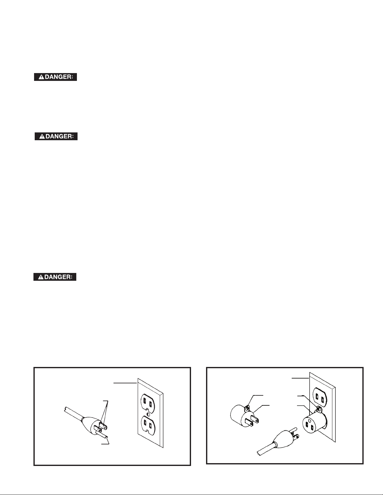
Use only 3-wire extension cords that have 3-prong grounding type plugs and matching 3-conductor receptacles that
accept the machine’s plug, as shown in Fig. A.
Repair or replace damaged or worn cord immediately.
IN ALL CASES, MAKE CERTAIN THE RECEPTACLE IN QUESTION IS PROPERLY GROUNDED.
IF YOU ARE NOT SURE, HAVE A QUALIFIED ELECTRICIAN CHECK THE RECEPTACLE.
GROUNDED
OUTLET BOX
CURRENT
CARRYING
PRONGS
GROUNDING BLADE
IS LONGEST OF THE 3 BLADES
GROUNDED OUTLET BOX
GROUNDING
MEANS
ADAPTER
FIG. A FIG. B
5
Page 6
EXTENSION CORDS
Use proper extension cords. Make
sure your extension cord is in good
condition and is a 3-wire extension cord which has a
3-prong grounding type plug and matching
receptacle which will accept the machine’s plug.
When using an extension cord, be sure to use one
heavy enough to carry the current of the machine.
An undersized cord will cause a drop in line voltage,
resulting in loss of power and overheating. The table
shows the correct gauge to use depending on the
cord length. If in doubt, use the next heavier gauge.
The smaller the gauge number, the heavier the cord.
MINIMUM GAUGE EXTENSION CORD
RECOMMENDED SIZES FOR USE WITH STATIONARY ELECTRIC MACHINES
Ampere
Rating
0-6
0-6
0-6
0-6
6-10
6-10
6-10
6-10
10-12
10-12
10-12
10-12
12-16
12-16
12-16
Volts Total Length
120
120
120
120
120
120
120
120
120
120
120
120
120
120
120
of Cord in
Feet
up to 25
25-50
50-100
100-150
up to 25
25-50
50-100
100-150
up to 25
25-50
50-100
100-150
up to 25
25-50
GREATER THAN 50 FEET NOT RECOMMENDED
FIG. C
Gauge of Extension
Cord
18 AWG
16 AWG
16 AWG
14 AWG
18 AWG
16 AWG
14 AWG
12 AWG
16 AWG
16 AWG
14 AWG
12 AWG
14 AWG
12 AWG
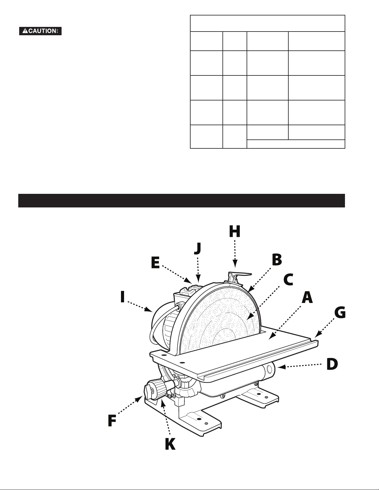
KEY FEATURES AND COMPONENTS
A. Cast iron tilting table
B. Disc plate
C. Sanding disc
D. 2 1/4” dust port
E. Power switch
F. Table locking wing nut
G. Miter gauge slot
H. Disc brake
I. ½ HP, 120V motor
J. Safety key
K. Table tilt adjustment knob
FIG. 1
6
Page 7

FUNCTIONAL DESCRIPTION
The DELTA® 12” Disc Sander is designed for sanding or polishing flat or beveled surfaces on wood and plastic materials.
PRODUCT SPECIFICATIONS
Speed: 1725 RPM
Disc Diameter: 12”
Table Tilt: +45° to -45°
Height: 15”
Width: 17 ¼”
Shipping Weight: 81 lbs
Motor: ½ HP, 120 V, 1 Phase, 60 HZ
Table Size: 17 ¼” x 6 ¼”
Dust Collection Outlet: 2 ¼”
Miter Gauge Groove: 3/8” x 3/4"
Length: 17 ¾”
Weight: 72 lbs
UNPACKING
The machine is heavy, be careful when removing it from the shipping container! Failure to comply may
cause serious injury and/or damage to the sander and/or property!
Your DELTA® 12” Disc Sander comes packed in a single container. Use a safety strap to avoid tip-over when lifting
machine. Check shipping carton and machine for damage before unpacking.
Open the shipping container. Carefully remove packaging materials, parts and machine from shipping carton. Always
check for and remove protective shipping materials around motors and moving parts. Lay out all parts on a clean work
surface and check that all parts are present and in good condition:
DESCRIPTION (QUANTITY)
• 12” disc sander (1)
• Dust collection hose with 2 ¼” port
adaptor (1)
• Brake lever assembly (1)
Compare the items to inventory figures; verify that all items are accounted for before discarding the shipping box. Report
any missing or damaged parts to your distributor or dealer. Prior to tool assembly and use, read this manual thoroughly
to familiarize yourself with proper assembly, maintenance and safety procedures.
Remove any protective materials and coatings from all of the parts and the disc sander. The protective coatings can be
removed by spraying WD-40 on them and wiping it off with a soft cloth. This may need redone several times before all of
the protective coatings are removed completely
If any parts are missing, do not attempt to plug in the power cord and turn “ON" the machine. The
machine should only be turned “ON" after all the parts have been obtained and installed correctly.
• Miter gauge
• 2.5mm Allen wrench (1)
• 4mm Allen wrench (1)
7
Page 8
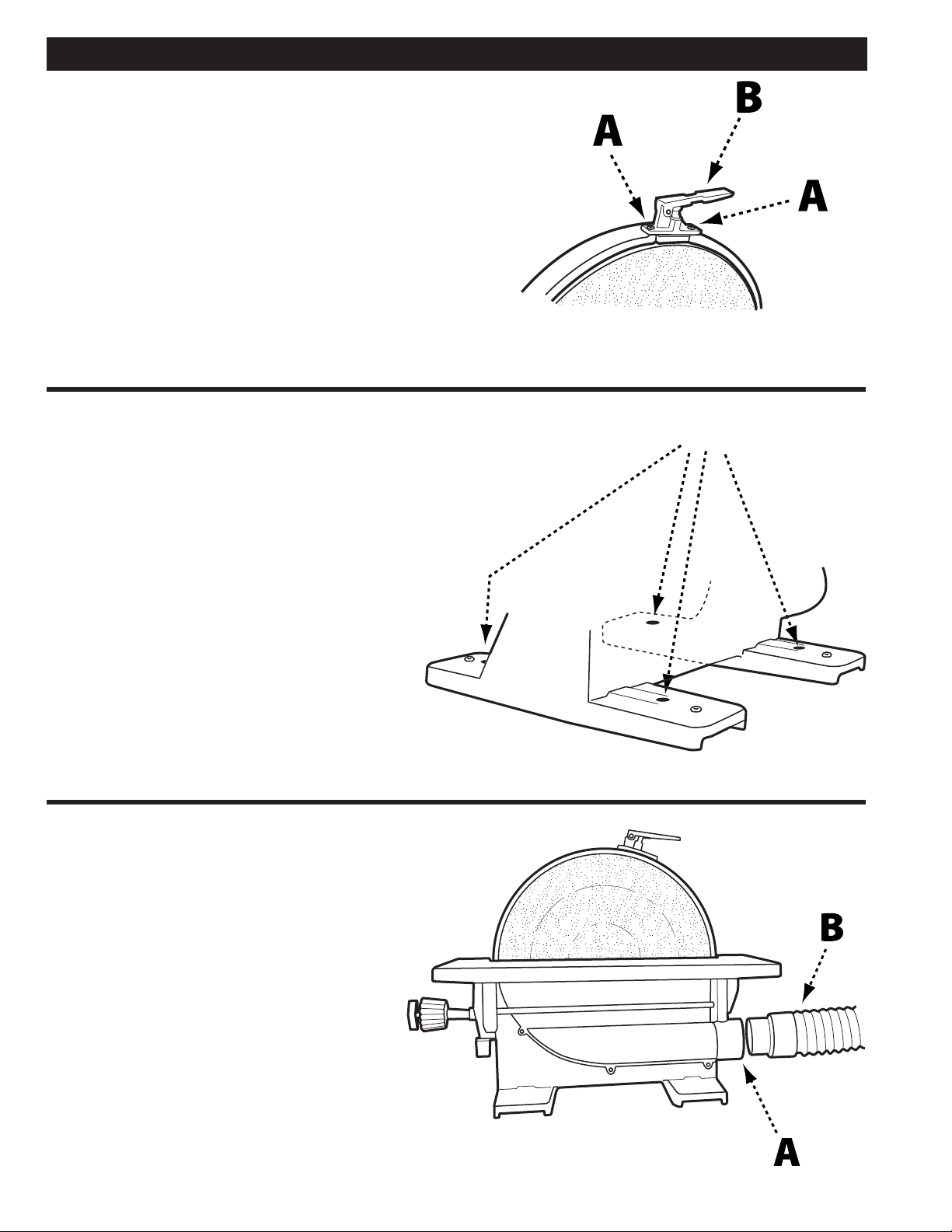
INSTALL BRAKE LEVER
ASSEMBLY
• Refer to Figure 2 and remove the 2 hex screws (A)
from the disc housing using the 2.5mm Allen wrench
supplied.
• Align the screw holes in the brake lever assembly (B)
with the holes in the disc housing and secure using the
hex screws removed in Step 1.
ASSEMBLY
FIGURE 2
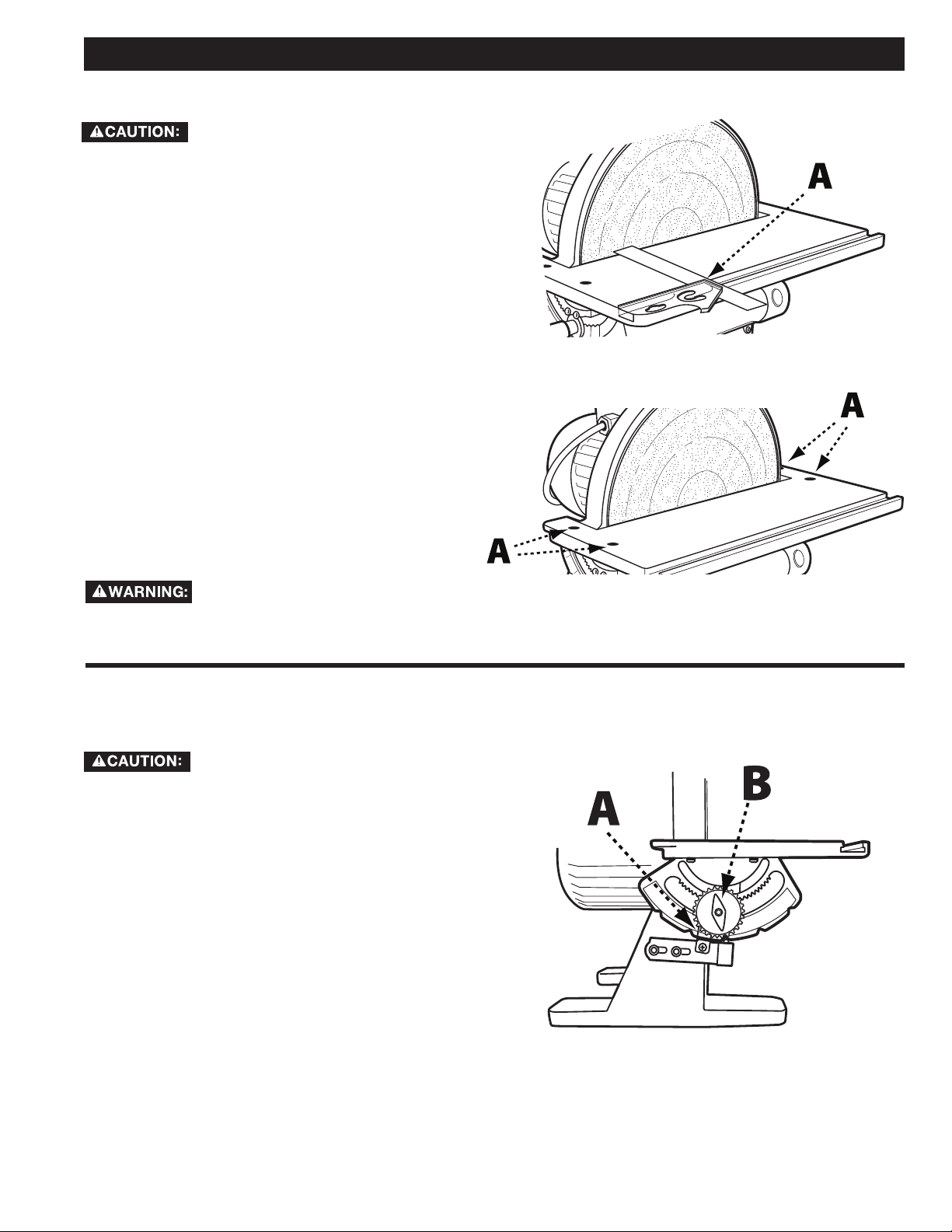
SECURE TOOL TO SUPPORTING SURFACE
Important: If during operation there is any tendency
for the sander to tip over, slide or walk on the
supporting surface, the sander must be secured to
the supporting surface.
To secure the sander to the supporting surface, use
screws or bolts and nuts through the four holes (A) as
shown in Figure 3.
CONNECT DUST HOSE TO
DUST COLLECTOR SYSTEM
A
FIGURE 3
The 12" Disc Sander has an efficient, integral
fan which provides excellent dust collection. It
is recommended that the machine be attached
to a dust collector using the 2 1/4” dust port (A)
shown in Figure 4.
If a dust collector is not available, insert one end
of the supplied dust hose (B) into the dust port
and place the other end of the dust hose into a
garbage can or other receptacle.
FIGURE 4
8
Page 9

OPERATION
STARTING AND STOPPING SANDER
Failure to read and understand the instructions, warnings and safety guidelines provided in this manual
may lead to serious injury and / or damage to machine or the work piece.
Be sure the sanding disc is securely installed onto the disc plate.
Make sure the table tilt locking levers are secured and that the table is locked in place at the desired
angle or tilt.
Make sure the machine is installed on a flat, sturdy and stable surface able to support the weight of the
machine and the work piece to be sanded.
NOTE: The DELTA® 12” Disc Sander uses a Safety Key
(A), shown in Figure 5. The Safety Key must be in place in
order to operate the machine. Before attempting to turn
on the sander, ensure the Safety Key is installed.
• The ON/OFF switch (B) is located on the top of the
motor. To turn the sander “ON”, move the switch
toward rear of sander.
• To turn the sander “OFF”, move switch to the front
position as shown.
NOTE: The sanding disc on this sander rotates
counterclockwise. In order to prevent injury and
produce good results, always sand on the left side
of the table only. Never work on the right side of the
table where the disc is rotating up as it is difficult to
control the work piece.
REMOVING THE SAFETY KEY TO LOCK SANDER
When the tool is not in use, the switch should be locked
in the “OFF” position. This can be done by grasping
the Safety Key (A), shown in Figure 5, and pulling it out
of the switch. With the Safety Key removed the switch
will not operate. Should the Safety Key be removed
while the machine is running, the switch can be turned
“OFF” once, but cannot be restarted without inserting
the Safety Key.
USING THE MANUAL DISC BRAKE
Apply the brake when the switch is in
the “off” position only. Applying the
brake while switch is in the “on” position may
damage the machine.
This 12" Disc Sander is equipped with a manual disc
brake that brings the sanding disc to a safe stop once
the power switch has been turned to the “OFF” position.
The manual disc brake should only be used once the
sander has been turned off. To apply the manual disc
brake, press down on brake lever (A) as shown in Figure
6.
FIGURE 5
FIGURE 6
9
Page 10

OPERATION
ANGLED AND END SANDING USING THE MITER GAUGE
The majority of work performed on the DELTA® 12” Disc
Sander is usually accomplished using the table as a
support. For accurate sanding of angled and end-grain
surfaces, as shown in Figure 7, your disc sander comes
with an adjustable miter gauge (A) and 3/8" x 3/4" t-slot
(B) machined into the table. To use the provided miter
gauge for angled or end-grain sanding , do the following:
make certain machine is
disconnected from power source
before making adjustments.
• Slide the miter gauge into the t-slot.
• Loosen the miter adjustment handle (C) by rotating it
to the left and adjust the miter gauge to the desired
sanding angle. Tighten the miter adjustment handle.
• Ensure the workpiece is positioned along the miter
gauge before turning the machine on and starting to
work.
BEVEL SANDING USING THE TABLE TILT
Make certain machine is
disconnected from power source
before making adjustments.
The table can be tilted up to 45 degrees up or down.
A scale (A), Figure 8, and pointer (B) are provided to
indicate the degree of tilt. Ball-indent positive stops on
the tilt adjustment indicator are located at 0°, 35°, and
45°.
To tilt the table up or down, loosen table locking wing
nut (C) and rotate the knob (D). As the knob is rotated,
the table will pivot either up or down. Turning the knob
clockwise will make the table tilt downward. Turning the
knob counterclockwise will tilt the table upward. Pivot
the table until desired angle is established. Then tighten
table locking wing nut.
Regardless of which position the
table is tilted, the table edge (E),
shown in Figure 10, must be no more than 1/16"
from the sanding disc to avoid trapping the work or
fingers between the table and sanding disc. To
adjust the position of the table relative to the
sanding disc, see “adjusting miter gauge slot
alignment “ on page 11.
table tilted down as shown in Figure 9; however, if
there is a need to tilt the table up, the workpiece
must be securely fastened or clamped to a fixture or
jig to prevent the workpiece from being torn from
hands and becoming trapped between the table and
sanding disc. See Figure 10.
FIGURE 7
We suggest that all bevel sanding
applications be performed with the
FIGURE 9
FIGURE 8
FIGURE 10
10
Page 11
ADJUSTMENTS
ADJUSTING MITER GAGE SLOT ALIGNMENT
Make certain machine is
disconnected from power source
before making adjustments.
• Check to see if the miter gage slot (A), shown in Figure
11, is parallel with the disc by placing a combination
square in the miter gage slot with one end of the
square against the disc as shown.
• Using a pencil, make a mark on the abrasive disc
where the square contacts the disc.
• Rotate the disc 180° and check the distance between
the disc and miter gauge slot at the opposite end of
the table. If an adjustment is necessary, proceed as
follows:
NOTE: When making the following adjustment, ensure
the table locking wing nut is tightened.
• Using the supplied hex wrench, loosen the four screws
(B) indicated in Figure 12, which secure the table to the
trunnions.
• Adjust the table by moving it in or out until the miter
gage slot is equidistant from the disc at both ends of
the table.
• Tighten the four screws securing the table to the
trunnions.
To avoid trapping the work or fingers
between the table and sanding disc,
the table edge should be positioned a maximum of
1/16" from the sanding disc.
FIGURE 11
FIGURE 12
SQUARING TABLE TO THE
SANDING DISC
Make certain machine is disconnected
from power source before making
adjustments.
• Referring to Figure 13, ensure table tilt indicator (A) is
set to 0°.
• Place an accurate square on the table with one end of
the square against the disc. If the table is not square to
the disc, proceed as follows:
• Loosen the table locking wing nut (B).
• Locate the 0° set screw which is located beneath the
table and loosen the retaining nut on the set screw.
• Rotate the 0° set screw and re-measure using the
square, repeating until the table is square with the
abrasive disc.
• Once the table is square, retighten the retaining nut on
the 0° set screw.
• Tighten table locking wing nut.
• Re-calibrate table tilt indicator by loosening the
indicator retaining screw and positioning the tilt
indicator to the 0° mark on the scale.
• Tighten indicator retaining screw.
FIGURE 13
11
Page 12
RECOMMENDED MAINTENANCE
NOTE: Disconnect machine from power source before
performing any maintenance.
LUBRICATION
All bearings are sealed and permanently lubricated. No
further lubrication is needed.
ROUTINE INSPECTION
It is recommended that you periodically inspect your
spindle sander as a precautionary action. During this
time, check for the following:
• Inspect all hardware, fittings and fasteners that may
have loosened due to vibration and re-tighten as
needed.
• Check for dust and/or wood particles that may have
accumulated on or in the machine. Check all dust
collection fittings – re-tighten as needed.
• Inspect the ON/OFF SWITCH for damage before each
use. Periodically inspect the power cord and plug for
damage. If necessary replace the power cord and the
plug at the first signs of visible damage.
REPLACING THE SANDING DISC
Make certain machine is
disconnected from power source.
• To remove sanding disc (A), simply peel old abrasive
disc from machine as shown.
• To install a new abrasive disc, make sure the disc plate
(B) is clean, dry, and free from any oil, grease, or old
adhesive.
• Peel back half the adhesive backing from the new disc
and slide between the table and disc plate so that the
half without the backing is aligned with the top half of
the disc plate.
• Press top half of sanding disc onto top half of disc
plate.
• Manually rotate disc plate one-half turn, remove
remainder of adhesive backing and firmly press sanding
disc onto disc plate.
Make certain the sanding disc is
securely in position before connecting
machine to a power source.
ACCESSORIES
A complete line of accessories is available from your DELTA® Supplier, DELTA® Factory Service Centers, and DELTA®
Factory Service Centers, and DELTA® Authorized Service Centers. Please visit our Web Site www.DeltaMachinery.
com for an online catalog or for the name or your nearest supplier.
Since accessories other than those offered by DELTA® have not been tested with this product,
use of such accessories could be hazardous. For safest operation, only DELTA® recommended
accessories should be used with this product.
WARRANTY
To register your tool for warranty service visit our website at www.DeltaMachinery.com.
Five Year Limited New Product Warranty
DELTA® will repair or replace, at its expense and at its option, any new DELTA® machine, machine part, or machine accessory which in normal
use has proven to be defective in workmanship or material, provided that the customer returns the product prepaid to a DELTA® factory service
center or authorized service station with proof of purchase of the product within five years and provides DELTA® with reasonable opportunity
to verify the alleged defect by inspection. For all refurbished DELTA® product, the warranty period is 180 days. DELTA® will not be responsible
for any asserted defect which has resulted from normal wear, misuse, abuse or repair or alteration made or specifically authorized by anyone
other than an authorized DELTA® service facility or representative. Under no circumstances will DELTA® be liable for incidental or consequential
damages resulting from defective products. Some states do not allow the exclusion or limitation of incidental or consequential damages, so
the above limitation or exclusion may not apply to you. This warranty is DELTA®’s sole warranty and sets forth the customer’s exclusive remedy,
with respect to defective products; all other warranties, express or implied, whether of merchantability, fitness for purpose, or otherwise, are
expressly disclaimed by DELTA®. For further detail of warranty coverage and warranty repair information, visit www.DeltaMachinery.com or call
1-800-223-7278. This warranty gives you specific legal rights and you may have other rights which vary in certain states or provinces.
LATIN AMERICA: This warranty does not apply to products sold in Latin America. For products sold in Latin America, see country
specific warranty information contained in the packaging, call the local company or see website for warranty information.
12
Page 13

PARTS, SERVICE OR WARRANTY ASSISTANCE
All DELTA® Machines and accessories are manufactured to high quality standards and are serviced by a network of
DELTA® Factory Service Centers and DELTA® Authorized Service Centers. To obtain additional information regarding
your DELTA® quality product or to obtain parts, service, warranty assistance, or the location of the nearest service center,
please call 1-800-223-7278.
REPLACEMENT PARTS
Use only identical replacement parts. For a parts list or to order parts, visit our website at www.DeltaMachinery.com. You can also order parts
from your nearest factory-owned branch, Authorized Warranty Service Center or by calling Technical Service Manager at 1-800-223-7278 to
receive personalized support from one of our highly-trained representatives.
FREE WARNING LABEL REPLACEMENT
If your warning labels become illegible or are missing, call
1-800-223-7278
for a free replacement.
SERVICE AND REPAIRS
All quality tools will eventually require servicing and/or replacement of parts. For information
about DELTA® Power Equipment Corporation, its factory-owned branches, or to locate
an Authorized Warranty Service Center, visit our website at www.DeltaMachinery.com
or call our Customer Care Center at 1-800-223-7278. All repairs made by our service centers are fully guaranteed against
defective material and workmanship. We cannot guarantee repairs made or attempted by others. By calling this number you
can also find answers to most frequently asked questions.
You can also write to us for information at DELTA® Power Equipment Corporation, 99 Roush Street, Anderson,
South Carolina 29625 - Attention: Technical Service Manager. Be sure to include all of the information shown on the
nameplate of your tool (model number, type, serial number, date code, etc.)
13
Page 14

CONSIGNES DE SÉCURITÉ IMPORTANTES
ASSUREZ-VOUS D’AVOIR BIEN LU ET COMPRIS TOUTES LES MISES EN
GARDE ET LES CONSIGNES D’UTILISATION AVANT D’UTILISER CET
ÉQUIPEMENT. Le fait de ne pas respecter toutes les instructions ci-dessous, peut
avoir pour conséquence : choc électrique, incendie et/ou blessures graves ou dégâts matériels.
Le travail du bois peut être dangereux si des procédures d’utilisation sécuritaires et adéquates ne sont pas respectées.
Comme c’est le cas pour toute pièce de machinerie, l’utilisation de ce produit comporte certains dangers. En utilisant
cet appareil selon les directives et avec prudence, vous réduirez de façon importante les risques de blessures
corporelles. Cependant, si les précautions normales de sécurité sont négligées ou ignorées, la personne qui utilise
l’appareil pourrait être blessée. L’équipement de protection comme les gardes, les poussoirs, les dispositifs de retenue,
les planches de protection, les lunettes de sécurité, les masques antipoussière et la protection pour l’ouïe peut réduire
le risque de blessure. Cependant, même le meilleur dispositif de protection ne peut compenser un mauvais jugement,
un manque de prudence ou de l’inattention. Ayez toujours recours à votre bon sens et soyez prudent dans l’atelier. Si
une manœuvre a l’air dangereuse, ne l’effectuez pas. Essayez plutôt de trouver un moyen plus facile. RAPPELEZ-VOUS
: Vous êtes responsable de votre propre sécurité. Pour des renseignements complémentaires, rendez-vous sur notre site
web à l’adresse www.DeltaMachinery.com.
Cet appareil a été conçu seulement pour certains types d’utilisation. DELTAMD Po wer
Equipment Corporation recommande fortement que cet appareil ne soit ni modifié ni utilisé à
toute autre fin que celles pour lesquelles il a été conçu. Si vous avez des questions sur un type d’utilisation en particulier,
N’UTILISEZ PAS l’appareil avant d’avoir d’abord contacté DELTAMD pour déterminer si elle peut ou si elle devrait être
réalisée avec ce produit.
Si vous avez des questions sur son utilisation, N’UTILISEZ PAS le produit tant que vous n’avez pas écrit à DELTAMD Power
Equipment Corporation et obtenu une réponse de leur part. Contactez-nous en ligne sur www.DeltaMachinery.com ou par
courrier à l’adresse suivante: responsable du service technique, DELTAMD Power Equipment Corporation, 99 Roush Street,
Anderson, South Carolina 29625.
• Des renseignements au sujet de l’utilisation sécuritaire et appropriée de cet appareil sont disponibles auprès des sources
suivantes:
• Power Tool Institute, 1300 Sumner Avenue, Cleveland, OH 44115-2851 ou en ligne à l’adresse www.powertoolinstitute.
com
• National Safety Council, 1121 Spring Lake Drive, Itasca, IL 60143-3201
• American National Standards Institute, 25 West 43rd Street, 4 floor, New York, NY 10036 ou en ligne à l’adresse www.
ansi.org - ANSI 01.1 Safety Requirements for Woodworking Machines
• Réglementation du Département américain du travail (OSHA) à l’adresse www.osha.gov
CONSIGNES DE SÉCURITÉ - DÉFINITIONS
Ce manuel contient des informations qu’il est important de connaître et de comprendre. Ces informations ont pour but
d’assurer VOTRE SÉCURITÉ et de PRÉVENIR LES PROBLÈMES D’ÉQUIPEMENT. Pour vous aider à reconnaître ces
informations, nous utilisons les symboles ci-dessous. Veuillez lire le manuel et prêter attention à ces sections-là.
Indique une situation extrêmement dangereuse qui, si elle n’est pas évitée, entraînera la mort ou une
blessure grave.
Indique une situation potentiellement dangereuse qui, si elle n’est pas évitée, pourrait entraîner
la mort ou une blessure grave.
Indique une situation potentiellement dangereuse qui, si elle n’est pas évitée, peut entraîner une
blessure mineure ou modérée.
Utilisé sans le symbole d’avertissement, indique une situation potentiellement dangereuse qui, si elle
n’est pas évitée, peut endommager l’appareil.
14
Page 15

RÈGLES DE SÉCURITÉ GÉNÉRALES
LE NON-RESPECT DE CES RÈGLES PEUT ENTRAÎNER DES BLESSURES
PERSONNELLES GRAVES.
POUR VOTRE PROPRE SÉCURITÉ, ASSUREZ-VOUS D’AVOIR BIEN LU ET COMPRIS LE MANUEL
•
D’UTILISATION AVANT DE FAIRE FONCTIONNER L’APPAREIL.
ses limites, ainsi que les dangers qui lui sont rattachés.
MAINTENEZ L’AIRE DE TRAVAIL PROPRE.
•
NE PAS UTILISER DANS UN ENVIRONNEMENT DANGEREUX.
•
ou mouillé, et ne l’exposez pas à la pluie. Gardez votre lieu de travail bien éclairé.
MAINTENEZ LES ENFANTS ET LES VISITEURS À L’ÉCART.
•
distance sécuritaire de l’aire de travail.
DÉBRANCHEZ L’APPAREIL
•
VÉRIFIEZ LA PRÉSENCE DE PARTIES ENDOMMAGÉES.
•
remplacer toute partie endommagée.
LE NON-RESPECT DE CES RÈGLES PEUT ENTRAÎNER DES BLESSURES GRAVES.
avant toute opération d’entretien.
Les aires et les bancs de travail encombrés sont propices aux accidents.
Apprenez à connaître son domaine d’utilisation et
N’utilisez pas cet appareil dans un endroit humide
Tous les enfants et visiteurs doivent demeurer à une
Avant d’utiliser l’appareil, assurez-vous de bien réparer ou
1. Assurez-vous de lire et comprendre les
avertissements affichés sur l’appareil et dans ce
manuel. Le non-respect de tous ces avertissements
peut entraîner des blessures graves.
2. Remplacer les étiquettes d’avertissement si elles sont
masquées ou si elles ont été retirées.
3. Cette ponceuse à disque est conçue pour l’utilisation
par un personnel qualifié et expérimenté seulement.
Si vous n’avez pas l’habitude d’utiliser correctement
et en toute sécurité une ponceuse de contour,
ne vous en servez pas avant d’avoir acquis les
connaissances et la formation appropriées.
4. Ne pas utiliser cet appareil pour autre chose que
son usage prévu. S’il est utilisé à d’autres fins,
DELTAMD Power Equipment Company, Inc. décline
toute garantie réelle ou implicite et se dégage de
toute responsabilité pour toute blessure qui pourrait
résulter de cette utilisation.
5. Portez toujours des lunettes/masque de protection
agréés durant l’utilisation de cette ponceuse à
disque.
6. Avant d’utiliser cette ponceuse, enlevez cravate,
bagues, montres et autres bijoux, et retroussez vos
manches au-dessus du coude. Retirez tous les
vêtements amples et retenez les cheveux longs.
Il est recommandé de porter des chaussures
antidérapantes ou de poser des bandes de plancher
antidérapantes. Ne pas porter de gants.
7. Portez des protecteurs pour l’ouïe (bouchons ou
manchons) pendant les longues périodes d’utilisation.
8. Certaines poussières produites par les activités
de ponçage, de sciage, de meulage, de perçage
ainsi que d’autres activités de construction peuvent
contenir des produits chimiques pouvant causer
le cancer, des anomalies congénitales ou d’autres
problèmes liés aux fonctions reproductrices. En voici
des exemples:
• Plomb de peintures à base de plomb;
• Silice cristalline de briques, de ciment et d’autres
produits de maçonnerie;
• Arsenic et chrome de bois de sciage traité
chimiquement.
Votre risque à ces expositions varie, selon la
fréquence à laquelle vous effectuez ce genre
d’activité. Pour réduire l’exposition à ces produits
chimiques, travaillez dans un endroit bien ventilé et avec
de l’équipement de protection approuvé, comme les
masques antipoussières spécialement conçus pour filtrer
les particules microscopiques
9. Ne pas utiliser cet appareil en état de fatigue ou avec
les facultés affaiblies par la drogue, l’alcool ou les
médicaments.
10 Avant de brancher l’appareil sur la source
d’alimentation, assurez-vous que le commutateur est
en position «OFF» (« Arrêt»).
11. Assurez-vous que la machine est correctement mise
à la terre.
12. Faites les réglages de la machine ou son entretien
que lorsque celle-ci est débranchée de la source
d’alimentation.
13. Prenez l’habitude de vérifier que tout l’équipement
supplémentaire comme les clés de réglage, les clés
à molette, la ferraille, le matériel et les chiffons de
nettoyage a été éloigné de la machine avant de la
mettre en marche.
14. Gardez les dispositifs de protection en place en tout
temps lorsque l’appareil est utilisé. Faites preuve
d’une extrême prudence s’ils sont enlevés à des
fins d’entretien et remettez-les en place dès la fin de
l’entretien.
15. Assurez-vous de la stabilité de la ponceuse avant de
l’utiliser.
16. Vérifiez si des parties sont endommagées. Avant
d’utiliser l’appareil, il faut vérifier soigneusement
le dispositif de protection ou toute autre partie
endommagée afin de s’assurer que l’appareil
fonctionnera correctement et remplira sa fonction
prévue. Vérifiez l’alignement des pièces mobiles
15
Page 16

et leurs joints, tout bris de pièce et du cadrage et
toute autre condition qui pourrait en modifier
le fonctionnement. Toute garde ou autre partie
endommagée doit être réparée ou remplacée sans
délai.
17. Prévoyez un espace suffisant autour de la zone de
travail et un éclairage en plongée non éblouissant.
18. Gardez le plancher autour de l’appareil propre et
exempt de débris, d’huile et de graisse.
19. Gardez les visiteurs à une distance sécuritaire de la
zone de travail. Tenez les enfants à distance.
20. Sécurisez votre atelier pour les enfants avec des
cadenas, des commutateurs principaux ou en retirant
les clés de mise en marche.
21. Concentrez-vous uniquement sur le travail. Regarder
aux alentours, tenir une conversation et faire du
« chahut » sont des actes négligents qui peuvent
entraîner des blessures graves.
22. Ayez toujours une posture stable afin de ne pas
tomber et de ne pas vous appuyer contre le disque
de ponçage ou d’autres éléments en mouvement.
Évitez de vous pencher trop en avant ou de forcer de
manière excessive en utilisant l’appareil.
23. Utilisez l’outil approprié à la bonne vitesse et au
bon débit. Ne forcez pas un outil ou un accessoire
à effectuer une tâche pour laquelle il n’a pas été
conçu. Le bon outil fera mieux le travail et sera plus
sécuritaire.
24. Utilisez les pièces recommandées. Les accessoires
inadéquats peuvent être dangereux.
25. Entretenez les appareils avec soin. Suivez les
indications pour la lubrification et le changement
d’accessoires.
26. Débranchez l’appareil avant le nettoyage. Utilisez une
brosse ou de l’air comprimé pour enlever la poussière
ou des débris; n’utilisez pas vos mains.
27. Ne vous tenez pas debout sur l’appareil. Des
blessures graves pourraient se produire si l’appareil
se renverse.
28. Ne jamais laisser l’appareil sans surveillance lorsqu’il
est en marche. Débranchez l’appareil et ne le laissez
pas sans surveillance jusqu’à son arrêt complet.
29. Tenez la poignée fermement en tout temps.
30. N’utilisez pas cette ponceuse pour d’autres fins
que celles pour lesquelles elle est prévue. Si elle est
utilisée à d’autres fins, DELTAMD Power Equipment
Company Inc. décline toute garantie réelle ou
implicite et se dégage de toute responsabilité pour
toute blessure qui pourrait résulter de cette utilisation.
Familiarisez-vous avec les règles de sécurité enseignées
dans ce manuel:
Cela signifie que le non-respect des précautions peut
entraîner des blessures superficielles et/ou endommager
l’appareil.
Cela signifie que le non-respect des précautions peut
causer des blessures graves pouvant même entraîner la
mort.
CONSERVER CES CONSIGNES.
Consultez-les souvent et utilisez-les pour enseigner aux autres.
16
Page 17

RACCORDEMENTS
Un circuit électrique séparé devrait être utilisé pour vos appareils. Les fils du circuit doivent être au moins de calibre 12
et être protégés par un fusible à action différée de 20ampères. Si vous utilisez une rallonge, ne prenez que des rallonges
à troisfils avec des fiches de mise à la terre à troisbroches et le réceptacle correspondant qui acceptera la fiche de
l’appareil. Avant de brancher l’appareil sur l’alimentation, assurez-vous que le commutateur est en position « OFF»
(«Arrêt ») et que le courant électrique que vous allez utiliser possède les mêmes caractéristiques que celui indiqué
sur l’appareil. Tous les raccordements doivent établir un bon contact. Une utilisation en basse tension endommagera
l’appareil.
NE PAS UTILISER L’APPAREIL DANS UN ENDROIT HUMIDE OU MOUILLÉ ET NE PAS
L’EXPOSER À LA PLUIE.
SPÉCIFICATIONS DU MOTEUR
Votre appareil est câblé pour un courant alternatif de 115Volts, 60 Hz. Avant de raccorder l’appareil à la source
d’alimentation, assurez-vous que l’interrupteur est positionné sur «OFF» (ARRÊT).
CONSIGNES DE MISE À LA TERRE
CET APPAREIL DOIT ÊTRE MIS À LA TERRE LORSQU’IL EST UTILISÉ POUR PROTÉGER
L’OPÉRATEUR CONTRE L’ÉLECTROCUTION.
1. Pour tous les appareils raccordés à un cordon d’alimentation et mis à la terre :
En cas demauvais fonctionnement ou de panne, lamise à la terre fournit un chemin de moindre résistance au courant
électrique visant à réduire le risque d’électrocution. Cet appareil est équipé d’un cordon électrique possédant un
conducteur de terre et une fiche de terre. La fiche doit être branchée sur une prise correspondante qui est correctement
installée etmise à la terre, conformément à tous les codes et les règlements locaux.
Ne pasmodifier la fiche prévue. Si elle n’entre pas dans la prise, faire installer une prise appropriée par un électricien
agréé.
Le raccordement inapproprié du conducteur de terre de l’équipement peut provoquer l’électrocution. Le fil conducteur
avec un isolant comportant une surface extérieure verte, avec ou sans rayures jaunes, est le conducteur de terre. Si la
réparation ou le remplacement du cordon électrique ou de la fiche s’avère nécessaire, ne pas raccorder le conducteur de
terre de l’équipement à une borne sous tension.
Si les consignes demise à la terre ne sont pas complètement comprises ou en cas de doute concernant la mise à la
terre de l’appareil, se renseigner auprès d’un électricien ou du personnel de service agréés.
Utiliser uniquement des rallonges à troisfils avec des fiches demise à la terre à troisbroches et des réceptacles adaptés
à la fiche de l’appareil, comme indiqué à la Fig.A.
Réparer ou remplacer immédiatement tout cordon endommagé ou usé.
DANS TOUS LES CAS, ASSUREZ-VOUS QUE LE RÉCEPTACLE EN QUESTION EST BIEN RELIÉ
À LA TERRE. SI VOUS N’ÊTES PAS CERTAIN, FAITES VÉRIFIER LE RÉCEPTACLE PAR UN
ÉLECTRICIEN QUALIFIÉ.
BOÎTE DE COURANT
DE MISE À LA
TERRE
BROCHES
PORTEUSES DE
COURANT
LA BROCHE DE
MISE À LA TERRE EST LA PLUS
LONGUE DES TROIS
FIG. A FIG. B
17
BOÎTE DE COURANT
DE MISE À LA TERRE
MOYENS DE MISE
À LA TERRE
ADAPTATEUR
Page 18

RALLONGES
Utiliser des rallonges appropriées.
S’assurer que la rallonge est en bon
état et qu’il s’agit d’une rallonge à trois fils avec une
fiche de mise à la terre à troisbroches et d’un réceptacle
correspondant à la fiche de l’appareil. Lorsque vous
utilisez une rallonge, assurez-vous qu’elle soit de calibre
suffisamment élevé pour assurer l’alimentation de
l’appareil. Une rallonge d’un calibre trop petit provoquera
une chute de tension, entraînant une perte de puissance
et une surchauffe. Le tableau indique le bon calibre à
utiliser en fonction de la longueur de la rallonge. En cas de
doute, utiliser le calibre immédiatement supérieur. Plus le
numéro de calibre est petit, plus le cordon est épais.
CALIBRE MINIMUM POUR RALLONGE
CALIBRES RECOMMANDÉS POUR UTILISATION SUR DES APPAREILS ÉLECTRIQUES STATIONNAIRES
Ampérage Volts Longueur totale du
0 À 6
0 À 6
0 À 6
0 À 6
6 À 10
6 À 10
6 À 10
6 À 10
10 À 12
10 À 12
10 À 12
10 À 12
12 À 16
12 À 16
12 À 16
120
120
120
120
120
120
120
120
120
120
120
120
120
120
120
cordon en pieds
JUSQU’À 25 PI
25 À 50 (7,62 À 15,24 M)
50 À 100 (15,24 À 30,48 M)
100 À 150 (30,48 À 45,72 M)
JUSQU’À 25 PI
25 À 50 (7,62 À 15,24 M)
50 À 100 (15,24 À 30,48 M)
100 À 150 (30,48 À 45,72 M)
JUSQU’À 25 PI
25 À 50 (7,62 À 15,24 M)
50 À 100 (15,24 À 30,48 M)
100 À 150 (30,48 À 45,72 M)
JUSQU’À 25 PI
25 À 50 (7,62 À 15,24 M)
UNE LONGUEUR DE PLUS DE 50PI N’EST PAS RECOMMANDÉE.
FIG. C
Calibre de la
rallonge
18 AWG
16 AWG
16 AWG
14 AWG
18 AWG
16 AWG
14 AWG
12 AWG
16 AWG
16 AWG
14 AWG
12 AWG
14 AWG
12 AWG
CARACTÉRISTIQUES ET COMPOSANTES IMPORTANTES
A. Table en fonte inclinable
B. Support de disque
C. Disque de ponçage
D. Sortie de poussière de 5,71 cm
E. Interrupteur
F. Papillon de serrage de la table
G. Rainure pour guide à onglets
H. Frein à disque
I. Moteur de 1/2 HP, 120 V
J. Clé de sécurité
K. Bouton de réglage de l’inclinaison
de la table
18
FIG. 1
Page 19

DESCRIPTION FONCTIONNELLE
La ponceuse à disque DELTAMD de 30,5cm est conçue pour poncer ou polir les surfaces plates ou inclinées sur des
matériaux en bois et en plastique.
SPÉCIFICATIONS DU PRODUIT
Vitesse : 1725 tr/min
Diamètre du disque : 30,5cm
Inclinaison de la table : de +45° à -45°
Hauteur : 38,10cm
Largeur : 43,81cm
Poids à l’expédition : 36,74kg
Moteur : 1/2 HP, 120V, 1Phase, 60Hz
Dimension de la table : 43,81cm par 15,87cm
Orifice de dépoussiérage: 5,71cm
Rainure pour guide à onglets : 0,95 cm par 1,90cm
Longueur : 45,08cm
Poids : 32,65kg
DÉBALLAGE
L’appareil est lourd, soyez prudent lorsque vous le retirez de l’emballage d’expédition! Le nonrespect des indications peut entraîner des blessures graves et/ou endommager la ponceuse et/
ou le matériel!
Votre ponceuse à disque DELTAMD de 30,5cm est livrée dans un emballage unique. Placez une sangle de sécurité autour
de l’appareil pour éviter qu’il ne bascule lors du levage. Vérifiez la présence de dommages sur le carton d’expédition et
l’appareil avant de le déballer.
Ouvrez l’emballage d’expédition. Enlevez soigneusement les matériaux d’emballage, les pièces et l’appareil de
l’emballage d’expédition. Toujours vérifier et retirer les matériaux d’emballage de protection autour des moteurs et des
pièces mobiles. Étalez toutes les pièces sur une surface de travail propre et vérifiez que toutes les pièces sont présentes
et en bon état:
DESCRIPTION (QUANTITÉ)
• Ponceuse à disque de 30,5cm (1)
• Tuyau de dépoussiérage avec sortie de
poussière de 5,71cm adaptateur (1)
• Ensemble de levier de frein (1)
• Guide à onglets
• Clé Allen de 2,5mm (1)
• Clé Allen de 4mm (1)
Comparez les articles avec la liste d’inventaire. Vérifiez la présence de tous les éléments avant de jeter la boîte
d’expédition. Signalez toute pièce manquante ou endommagée à votre distributeur ou à votre revendeur. Avant de
passer à l’assemblage de l’appareil et à son utilisation, lisez attentivement le présent manuel pour vous familiariser avec
les procédures d’assemblage, d’entretien et de sécurité appropriées.
Retirez tout matériau de protection et tout emballage de l’ensemble des éléments et de la ponceuse à disque. Les
enduits de protection peuvent être enlevés en les pulvérisant de WD-40 et en les essuyant avec un chiffon doux. Il peut
être nécessaire de répéter cette étape plusieurs fois pour enlever l’intégralité des enduits de protection.
S’il y a des pièces manquantes, n’essayez pas de brancher le cordon d’alimentation et de
mettre l’appareil en marche (« ON »). L’appareil doit seulement être mis en marche (« ON »)
quand toutes les pièces auront été obtenues et correctement installées.
19
Page 20

ASSEMBLAGE
INSTALLATION DE L’ENSEMBLE
DE LEVIER DE FREIN
• Référez-vous à la Figure2 et retirez les 2vis à 6pans
(A) du support de disque en utilisant la clé Allen de
2,5mm fournie.
• Alignez les trous de vis de l’ensemble de levier de
frein (B) avec ceux du support de disque et fixez ces
deux parties en utilisant les vis à 6 pans que vous avez
retirées à l’étape1.
FIGURE 2
POSITIONNEMENT DE L’OUTIL SUR LA
SURFACE D’APPUI
Important : Pendant l’utilisation, si la ponceuse a
tendance à basculer, glisser ou se déplacer, celle-ci
doit être solidement fixée sur la surface d’appui.
Pour fixer la ponceuse sur la surface d’appui, placez des
vis ou des boulons et des écrous dans les quatre trous
(A) comme indiqué à la Figure 3.
CONNEXION DU TUYAU DE
DÉPOUSSIÉRAGE AU SYSTÈME
DE DEPOUSSIÉRAGE
A
FIGURE 3
La ponceuse à disque de 30,5cm a un ventilateur
intégré efficace qui permet une excellente
récupération de la poussière. Il est recommandé
de connecter l’appareil à un dispositif de
dépoussiérage avec la sortie de poussière de
5,71cm (A) comme indiqué à la Figure4.
Si vous ne possédez pas de dispositif de
dépoussiérage, insérez une extrémité du tuyau
fourni (B) dans la sortie de poussière et placez
l’autre extrémité du tuyau dans une poubelle ou
tout autre récipient.
FIGURE 4
20
Page 21

FONCTIONNEMENT
DÉMARRAGE ET ARRÊT DE LA PONCEUSE
Le fait de ne pas lire et comprendre les instructions, les avertissements et les consignes de sécurité
fournis dans ce manuel peut causer de graves blessures et/ou des dommages à l’appareil ou à la
pièce en cours d’usinage.
Assurez-vous que le disque de ponçage est bien installé sur le support de disque.
Assurez-vous que les poignées de blocages de l’inclinaison de la table sont bien serrées et que la
position de la table est verrouillée selon l’angle ou l’inclinaison désirés.
Assurez-vous que l’appareil est installé sur une surface plane, robuste et stable capable de supporter
le poids de l’appareil et de la pièce à poncer.
REMARQUE : La ponceuse à disque DELTAMD de 30,5 cm
utilise une clé de sécurité (A), comme il est indiqué à la
Figure5. La clé de sécurité doit être enclenchée pour pouvoir
utiliser l’appareil. Avant de procéder au démarrage de la
ponceuse, vérifiez que la clé de sécurité est installée.
• L’interrupteur ON/OFF (MARCHE/ARRÊT) (B) est situé sur
le dessus du moteur. Pour démarrer la ponceuse («ON»),
déplacez l’interrupteur vers l’arrière de la ponceuse.
• Pour arrêter la ponceuse («OFF»), déplacez l’interrupteur
vers l’avant comme indiqué.
REMARQUE : Le disque de ponçage de la ponceuse
tourne dans le sens inverse des aiguilles d’une montre.
Afin d’éviter les blessures et de produire les meilleurs
résultats, ne poncer que sur le côté gauche de la table. Ne
travaillez jamais du côté droit de la table, là où le disque
tourne vers le haut, car il est difficile de contrôler la pièce à
travailler.
FIGURE 5
RETRAIT DE LA CLÉ DE SÉCURITÉ POUR VERROUILLER LA
PONCEUSE
Lorsque l’appareil n’est pas utilisé, l’interrupteur doit
être verrouillé sur la position «OFF» (ARRÊT). Ceci peut
être effectué en saisissant la clé de sécurité (A), comme
indiqué à la Figure5, et en la retirant de l’interrupteur.
Une fois la clé de sécurité retirée, l’interrupteur ne
fonctionnera plus. Si la clé de sécurité est retirée durant
le fonctionnement de l’appareil, l’interrupteur pourra être
positionné sur « OFF » (ARRÊT) une seule fois, mais ne
pourra être redémarré qu’en insérant la clé de sécurité.
UTILISATION DU FREIN À DISQUE MANUEL
Posez le frein seulement
quand l’interrupteur est
positionné sur « OFF » (ARRÊT). Poser le frein quand
l’interrupteur est positionné sur « ON » (MARCHE)
peut endommager l’appareil.
Cette ponceuse à disque de 30,5cm est équipée d’un
frein à disque manuel qui assure un arrêt du disque
de ponçage en toute sécurité une fois l’interrupteur
positionné sur « OFF » (ARRÊT). Le frein à disque doit
être utilisé qu’une fois la ponceuse est éteinte. Pour
poser le frein à disque manuel, poussez le levier de frein
vers le bas (A) comme indiqué à la Figure6.
21
FIGURE 6
Page 22

FONCTIONNEMENT
UTILISATION DU GUIDE À ONGLETS POUR LE PONÇAGE INCLINÉ
ET LE PONÇAGE DE BOIS DE BOUT
La plupart des travaux accomplis avec la ponceuse
à disque de 30,5 cm DELTAMD sont généralement
réalisés en se servant de la table comme support. Pour
un ponçage précis de surfaces inclinées ou de bois
de bout, comme indiqué à la Figure 7, votre disque
de ponçage est accompagné d’un guide à onglets
ajustables (A) et d’une rainure en «T » de 0,95 cm par
1,90cm (B) usinée dans la table. Pour utiliser le guide à
onglets fourni pour les surfaces inclinées ou de bois de
bout, procédez comme suit:
Assurez-vous que l’appareil est
débranché avant de réaliser les
réglages.
• Faites glisser le guide à onglets dans la rainure en
«T».
• Relâchez la poignée de réglage de l’onglet (C) en la
UTILISATION DE L’INCLINAISON DE LA TABLE POUR UN
PONÇAGE EN BISEAU
Assurez-vous que l’appareil est
débranché avant de réaliser les
réglages.
La table peut s’incliner jusqu’à 45degrés vers le haut
ou vers le bas. Un niveau (A), Figure8, et une aiguille
(B) sont fournis pour indiquer le degré d’inclinaison.
Des butées fixes sont localisées sur l’indicateur de
réglage de l’inclinaison à 0°, 35° et 45°.
Pour incliner la table vers le haut ou vers le bas,
desserrez le papillon de serrage de la table (C) et
tournez le bouton (D). Une fois le bouton tourné, la
table pivotera vers le haut ou vers le bas. En tournant
le bouton dans le sens des aiguilles d’une montre, la
table s’inclinera vers le bas. En tournant le bouton dans
le sens inverse des aiguilles d’une montre, la table
s’inclinera vers le haut. Faites pivoter la table jusqu’à
obtenir l’angle désiré. Resserrez ensuite le papillon de
serrage de la table.
Quelle que soit la position
dans laquelle la table est
inclinée, le bord de la table (E), indiqué à la Figure 10,
ne doit pas être à une distance de plus de 15 mm du
disque de ponçage pour éviter de coincer la pièce ou
de se coincer les doigts entre la table et le disque de
ponçage. Pour régler la position de la table par
rapport au disque de ponçage, passez à la section
tournant vers la gauche et ajustez le guide à onglets
selon l’angle de ponçage désiré. Resserrez la poignée
de réglage de l’onglet.
• Assurez-vous que la pièce est positionnée contre le
guide à onglets avant de démarrer l’appareil et de
commencer à travailler.
FIGURE 7
« réglage de l’alignement de la rainure pour guide à
onglets » à la page 23.
Nous conseillons d’effectuer
tous les ponçages en biseau
en inclinant la table vers le bas comme indiqué à la
Figure 9; cependant, si l’inclinaison vers le haut est
nécessaire, la pièce à travailler doit être fermement
attachée ou fixée à une installation ou un gabarit
pour empêcher la pièce d’être arrachée des mains et
de se retrouver coincée entre la table et le disque de
ponçage. Voir Figure 10.
FIGURE 9
FIGURE 8 FIGURE 10
22
Page 23

AJUSTEMENTS
RÉGLAGE DE L’ALIGNEMENT DE LA RAINURE POUR
GUIDE À ONGLETS
Assurez-vous que l’appareil est
débranché avant de réaliser les réglages.
• Vérifiez que la rainure du guide à onglets (A), indiquée à
la Figure11, est parallèle au disque en positionnant une
équerre combinée dans la rainure pour guide à onglets avec
une des extrémités de l’équerre contre le disque comme
indiqué.
• Faites un repère au crayon sur le disque de ponçage à
l’endroit où l’équerre touche le disque.
• Faites tourner le disque à 180° et vérifiez la distance entre le
disque et la rainure du guide à onglets à l’extrémité opposée
de la table. Si un réglage est nécessaire, procédez comme
suit :
REMARQUE : En réalisant les réglages ci-dessous, assurezvous que le papillon de serrage de la table est bien serré.
• En utilisant la clé à 6pans fournie, desserrez les quatrevis
(B) qui fixent la table aux tourillons, comme indiqué à la
Figure12.
• Ajustez la table en l’entrant ou en la sortant jusqu’à ce que
le guide à onglets soit équidistant du disque à chaque
extrémité de la table.
• Resserrez les quatrevis reliant la table aux tourillons.
Pour éviter de coincer la pièce à
travailler ou de se coincer les
doigts entre la table et le disque de ponçage, le bord de la
table doit être séparé de 15 mm maximum du disque de
ponçage.
FIGURE 11
FIGURE 12
AJUSTER LA TABLE PERPENDICULAIREMENT AU DISQUE DE
PONÇAGE
Assurez-vous que l’appareil est débranché
avant de réaliser les réglages.
• En vous aidant de la Figure13, assurez-vous que
l’indicateur d’inclinaison de la table (A) est positionné sur
0°.
• Placez une équerre précise sur la table en positionnant un
des côtés de l’équerre contre le disque. Si la table n’est pas
perpendiculaire au disque, procédez comme suit :
• Relâchez le papillon de serrage de la table (B).
• Localisez la vis de fixation de 0° située sous la table et
desserrez l’écrou de la vis de fixation.
• Tournez la vis de fixation de 0° et prenez à nouveau les
mesures en utilisant l’équerre, en répétant l’opération jusqu’à
ce que la table soit perpendiculaire au disque de ponçage.
• Une fois que la table est perpendiculaire, resserrez l’écrou de
serrage de la vis de fixation de 0°.
• Resserrez le papillon de serrage de la table.
• Calibrez de nouveau l’indicateur d’inclinaison de la table en
desserrant la vis de fixation de l’indicateur et en positionnant
l’indicateur d’inclinaison sur le repère 0° de la règle graduée.
• Resserrez la vis de fixation de l’indicateur.
FIGURE 13
23
Page 24

RECOMMANDATIONS D’ENTRETIEN
REMARQUE : Débranchez l’appareil de la source
d’alimentation avant d’effectuer toute opération
d’entretien.
GRAISSAGE
Tous les roulements sont étanches et sont graissés
de façon permanente. Aucun autre graissage n’est
nécessaire.
INSPECTION DE ROUTINE
Il est recommandé de vérifier périodiquement votre
ponceuse à broche à titre préventif. Ce faisant, vérifiez
les points suivants:
• Inspectez tous les matériels, raccords et attaches
susceptibles de se relâcher en raison des vibrations et
resserrez-les si nécessaire.
• Vérifiez si de la poussière et/ou des particules de bois
se sont accumulées sur ou dans l’appareil. Vérifiez
tous les raccords de dépoussiérage, et resserrez-les au
besoin.
• Avant chaque utilisation, inspectez l’interrupteur ON/
OFF (MARCHE/ARRÊT) pour vérifier qu’il n’est pas
endommagé. Inspectez périodiquement le cordon
d’alimentation et la fiche pour vérifier qu’ils ne sont
pas endommagés. Si nécessaire, remplacez le cordon
d’alimentation et la fiche aux premiers signes visibles
de dommages.
REMPLACEMENT DU DISQUE
DE PONÇAGE
Assurez-vous que l’appareil est
débranché de la source
d’alimentation.
• Pour retirer le disque de ponçage (A), tirez simplement
sur l’ancien disque de ponçage de l’appareil comme
indiqué.
• Pour mettre en place un nouveau disque de ponçage,
assurez-vous que le support de disque (B) est propre,
sec, et dépourvu d’huile, de graisse ou de traces
adhésives.
• Retirez la moitié du papier de protection du nouveau
disque et glissez-le entre la table et le support de
disque afin que la moitié non recouverte soit alignée
avec la moitié supérieure du support de disque.
• Pressez la moitié supérieure du disque de ponçage
contre la moitié supérieure du support de disque.
• Faites faire un demi-tour, manuellement, au support de
disque, retirez les traces d’adhésif restantes et pressez
fermement le disque de ponçage contre le support de
disque.
Avant de brancher l’appareil à
la source d’alimentation,
assurez-vous que le disque de ponçage est bien
positionné.
ACCESSOIRES
Une gamme complète d’accessoires peut être obtenue auprès de votre fournisseur DELTAMD , des centres de
service du fabricant DELTAMD, des centres de service du fabricant DELTAMD, et des centres de services agréés
DELTAMD. Rendez-vous sur notre site Web www.DeltaMachinery.com pour obtenir un catalogue en ligne ou pour
connaître le nom du fournisseur le plus près de chez vous.
Étant donné que les accessoires autres que ceux offerts par DELTAMD n’ont pas été
testés avec ce produit, leur utilisation pourrait s’avérer dangereuse. Pour assurer une
utilisation plus sécuritaire, seuls les accessoires recommandés par DELTAMD devraient être utilisés avec ce
produit.
GARANTIE
Pour l’enregistrement de votre outil auprès du service de la garantie, rendez-vous sur notre site à l’adresse www.
DeltaMachinery.com.
DELTAMD réparera ou remplacera, à ses frais et à sa discrétion, tout nouvel appareil, pièce ou accessoire de l’appareil de DELTAMD qui, pour une
usure normale, est jugé défectueux en raison d’un défaut de fabrication ou de matériau, à condition que le client retourne le produit prépayé
à un centre de service du fabricant ou à un centre de service autorisé DELTAMD avec une preuve d’achat du produit dans les cinq ans après
l’achat et offre à DELTAMD une occasion raisonnable de vérifier le défaut allégué au moyen d’une inspection. Pour tous les produits DELTAMD
reconditionnés, la durée de garantie est de 180 jours. DELTAMD ne peut être tenu responsable de tout défaut confirmé issu de l’usure normale,
d’une mauvaise utilisation, d’abus ou de réparations ou d’altérations faites ou expressément autorisées par quiconque autre qu’un centre
de service ou un représentant de DELTAMD autorisé. En aucun cas, DELTMD ne pourra être tenu pour responsable des dommages directs ou
indirects résultant de produits défectueux. Certains États ne permettant pas l’exclusion ou la limitation des dommages directs ou indirects, la
limitation ou exclusion peut ne pas s’appliquer à votre cas. Cette garantie est la seule garantie de DELTAMD, et elle devient le recours exclusif du
client en ce qui concerne les produits défectueux; toute autre garantie, expresse ou implicite, que ce soit de la valeur marchande, de la capacité
de remplir une fonction ou autre, est expressément exclue par DELTAMD. Pour plus de renseignements sur la couverture de la garantie et des
informations sur les réparations sous garantie, rendez-vous sur notre site à l’adresse www.DeltaMachinery.com ou appelez le 1 800 223-7278.
Cette garantie vous donne des droits légaux spécifiques et vous pouvez avoir d’autres droits qui sont différents selon les États ou provinces.
Garantie limitée de cinq ans pour les produits neufs
AMÉRIQUE LATINE : La présente garantie ne s’applique pas aux produits vendus en Amérique latine. Pour les produits vendus
en Amérique latine, veuillez consulter les renseignements au sujet de la garantie pour un pays particulier figurant sur l’emballage,
appeler la compagnie locale ou consulter notre site Web pour plus de renseignements au sujet de la garantie.
24
Page 25

AIDE POUR LES PIÈCES, LE SERVICE OU LA GARANTIE
Tous les appareils et accessoires DELTAMD sont fabriqués selon des normes de qualité élevées et sont soutenus par
un réseau de centres de service du fabricant DELTAMD et des centres de services DELTAMD autorisés. Pour en savoir
davantage sur votre produit de qualité DELTAMD ou pour obtenir des pièces, du service, de l’aide concernant la garantie
ou l’emplacement du centre de service le plus près de chez vous, veuillez composer le 1800223-7278.
PIÈCES DE RECHANGE
Utilisez uniquement des pièces de rechange identiques. Pour obtenir une liste de pièces ou commander des pièces, rendez-vous
sur notre site à l’adresse www.DeltaMachinery.com. Vous pouvez aussi commander des pièces auprès de votre représentant
local, du centre de service de garantie autorisé ou en appelant le responsable du service technique au 1800 223-7278 pour
recevoir une assistance personnalisée de la part d’un de nos représentants hautement qualifié.
REMPLACEMENT GRATUIT DES ÉTIQUETTES DE MISE EN GARDE
Si vos étiquettes de mise en garde sont devenues illisibles ou si vous les avez perdues, composez le 1800223-7278 pour un
remplacement gratuit.
SERVICE ET RÉPARATIONS
Tous les outils de qualité auront besoin de service et/ou d’un remplacement de pièces à un moment donné. Pour des
renseignements au sujet de DELTAMD Power Equipment Corporation, ses filiales en usine ou pour trouver un centre de service
de garantie autorisé, rendez-vous sur notre site à l’adresse www.DeltaMachinery.com ou appelez notre service à la clientèle
au 1800223-7278. Toutes les réparations réalisées par nos centres de service sont entièrement garanties contre les défauts de
matériau et de fabrication. Nous ne pouvons garantir les réparations réalisées ou tentées par d’autres. En appelant ce numéro,
vous pouvez également obtenir des réponses aux questions les plus fréquemment posées .
Pour obtenir plus de renseignements, vous pouvez aussi nous écrire à l’adresse DELTAMD Power Equipment Corporation,
99 Roush Street, Anderson, SC 29625 - Attention: Responsable du service technique. Assurez-vous de fournir tous les
renseignements présents sur la plaque de votre outil (numéro de modèle, type, numéro de série, code de date, etc.)
25
Page 26

INSTRUCCIONES IMPORTANTES DE SEGURIDAD
LEA Y COMPRENDA TODAS LAS ADVERTENCIAS E INSTRUCCIONES
DE OPERACIÓN ANTES DE USAR ESTE EQUIPO. No cumplir con todas las
instrucciones enumeradas a continuación puede causar una descarga eléctrica, incendios y/o lesiones
personales graves o daños a la propiedad.
Trabajar con madera puede ser peligroso si no se observan procedimientos de operación seguros y adecuados. Tal
como sucede con toda maquinaria, existen determinados peligros asociados con la operación del producto. Utilizar
esta máquina con respeto y cautela disminuirá considerablemente la posibilidad de lesiones personales. Sin embargo,
no observar o ignorar las precauciones normales de seguridad podría causarle lesiones personales al operador. El
equipo de seguridad, como los protectores, las varillas para empujar, los sujetadores, las tablas con canto biselado, las
gafas protectoras, las máscaras para polvo y la protección auditiva pueden evitar el riesgo de lesionarse. Sin embargo,
incluso el mejor protector no compensará la falta de sentido común, el descuido ni la distracción. Siempre aplique
el sentido común y actúe con cautela en el taller. Si un procedimiento parece peligroso, no lo intente. Busque un
procedimiento alternativo que parezca más seguro. RECUERDE: Su seguridad personal es su responsabilidad. Para
obtener información adicional, visite nuestro sitio web en www.DeltaMachinery.com.
Esta máquina fue diseñada para determinadas aplicaciones únicamente. DELTA® Power Equipment Corporation
recomienda encarecidamente que esta máquina no sea modificada ni utilizada para un uso que no
sea para el cual fue diseñada. Si tiene alguna pregunta relacionada con un uso en particular, NO
utilice la máquina antes de haber contactado a DELTA® para determinar si puede o debe ser usada en el producto.
Si tiene alguna pregunta relacionada con su uso, NO utilice el producto hasta que haya escrito a DELTA® Power Equipment
Corporation y que le hayamos dado el asesoramiento adecuado. Comuníquese con nosotros por Internet en www.
DeltaMachinery.com o por correo postal a Technical Service Manager, DELTA® Power Equipment Corporation, 99 Roush Street,
Anderson, South Carolina29625.
• La información relacionada con la operación segura y adecuada de esta herramienta está disponible en las siguientes
fuentes:
• Power Tool Institute, 1300 Sumner Avenue, Cleveland, OH 44115-2851 o en Internet en www.powertoolinstitute.com
• National Safety Council, 1121 Spring Lake Drive, Itasca, IL 60143-3201
• American National Standards Institute, 25 West 43rd Street, 4 floor, New York, NY 10036 www.ansi.org - ANSI 01.1
Requisitos de seguridad para máquinas que trabajan con madera
• Reglamentaciones del Departamento del Trabajo de EE.UU.: www.osha.gov
NORMAS DE SEGURIDAD: DEFINICIONES
Este manual contiene información que es importante que usted conozca y comprenda. Esta información está
relacionada con la protección de SU SEGURIDAD y la PREVENCIÓN DE PROBLEMAS CON EL EQUIPO. Para ayudarle
a reconocer esta información, utilizamos los símbolos que figuran a continuación. Lea este manual y preste atención a
estas secciones.
Indica una situación peligrosa inminente que, de no evitarse, causará la muerte o lesiones graves.
Indica una situación potencialmente peligrosa que, de no evitarse, podría causar la muerte o
lesiones graves.
Indica una situación potencialmente peligrosa que, de no evitarse, puede causar lesiones menores o
moderadas.
Usado sin el símbolo de alerta de seguridad indica una situación potencialmente peligrosa que, de
no evitarse, puede causar daños a la propiedad.
26
Page 27

REGLAS GENERALES DE SEGURIDAD
OBSERVAR ESTAS REGLAS DE SEGURIDAD PUEDE OCASIONAR LESIONES PERSONALES
GRAVES.
POR SU PROPIA SEGURIDAD, LEA Y COMPRENDA EL MANUAL DE INSTRUCCIONES ANTES DE OPERAR
•
LA UNIDAD.
MANTENGA LIMPIA EL ÁREA DE TRABAJO.
•
NO USE EN ENTORNOS PELIGROSOS.
•
Mantenga el área de trabajo bien iluminada.
MANTENGA ALEJADOS A LOS NIÑOS Y VISITANTES.
•
distancia prudente del área de trabajo.
DESCONECTE LA UNIDAD
•
CONTROLE LAS PIEZAS DAÑADAS.
•
cualquier pieza que esté dañada.
Conozca los usos y las limitaciones de la unidad, así como los peligros específicos propios de la misma.
Las áreas y los bancos desordenados pueden provocar accidentes.
No use esta unidad en lugares húmedos o mojados, ni la exponga a la lluvia.
Todos los niños y visitantes deben mantenerse a una
antes de efectuarle tareas de mantenimiento.
Antes de seguir usando la unidad, repare o reemplace de forma adecuada
NO OBSERVAR ESTAS REGLAS DE SEGURIDAD PUEDE OCASIONAR LESIONES GRAVES.
1. Lea y comprenda los carteles de advertencia de la
máquina y de este manual. No cumplir con todas
estas advertencias puede causar lesiones graves.
2. Reemplace las etiquetas de advertencia si se tornan
borrosas o se desprenden.
3. Esta lijadora de disco ha sido diseñada para su
uso por parte de personal debidamente entrenado
y con la experiencia requerida únicamente. Si no
está familiarizado con el funcionamiento seguro y
adecuado de una lijadora de bordes, no la utilice
hasta haber recibido la capacitación adecuada y el
conocimiento correspondiente.
4. No utilice esta máquina para otra cosa que no sea
su uso previsto. Si se utiliza para otros propósitos,
DELTA® Power Equipment Company, Inc. se exime
de cualquier garantía real o implícita y se mantiene
indemne ante cualquier lesión que pueda derivarse
de dicho uso.
5. Siempre use lentes de seguridad/protectores de
rostro aprobados mientras utiliza esta lijadora de
disco.
6. Antes de operar esta lijadora, sáquese corbatas,
anillos, relojes y cualquier otra alhaja, y
arremánguese más arriba del codo. Quítese toda la
ropa suelta y sujétese el cabello largo. Se recomienda
el uso de calzado y franjas de piso antideslizantes.
No use guantes.
7. Use protectores auditivos (tapones u orejeras)
durante períodos de operación extensos.
8. Parte del polvo creado por el lijado, el aserrado,
el amolado, el barrenado y otras actividades de
construcción contiene productos químicos que se
sabe que causan cáncer, defectos congénitos y otros
daños reproductivos. Algunos ejemplos de estos
productos químicos son
• plomo de pinturas a base de plomo;
• sílice cristalina de ladrillos, cemento y otros productos
de albañilería;
• arsénico y cromo de madera tratada químicamente.
Su riesgo de exposición varía dependiendo de la
frecuencia con la que realice este tipo de trabajo.
Para reducir su exposición a estos productos químicos,
trabaje en un área bien ventilada y trabaje con equipos
de seguridad aprobados, como máscaras faciales y para
polvo que estén específicamente diseñadas para no dejar
pasar las partículas microscópicas.
9. No opere esta máquina cuando esté cansado o
bajo los efectos de drogas, alcohol o cualquier
medicamento.
10. Asegúrese de que el interruptor esté en la posición
OFF (APAGADO) antes de conectar la máquina a una
fuente de alimentación.
11. Asegúrese de que la máquina esté conectada a tierra
de forma adecuada.
12. Desenchufe la máquina de la fuente de alimentación
para realizar todos los ajustes y el mantenimiento de
la misma.
13. Cree el hábito de verificar que todos los equipos
adicionales, como llaves de ajuste, llaves, descartes,
material y paños de limpieza, se alejen de la máquina
antes de encenderla.
14. Mantenga los protectores de seguridad en su lugar
en todo momento cuando la máquina esté en
uso. Si se quitan por razones de mantenimiento,
aplique extrema precaución y vuelva a colocar los
protectores inmediatamente cuando se complete el
mantenimiento.
15. Asegúrese de que la lijadora esté firmemente sujeta
antes de proceder a su uso.
16. Examine las piezas dañadas. Antes de seguir
utilizando la máquina, debe examinarse
cuidadosamente si el protector u otra pieza
están dañados, para determinar que funcionarán
adecuadamente y desempeñarán su función prevista.
Examine la alineación de las piezas móviles, la unión
de las piezas móviles, si hay piezas rotas, el montaje
y cualquier otra condición que pueda afectar su
funcionamiento. Los protectores o las otras piezas
27
Page 28

que estén dañados deben repararse o reemplazarse
adecuadamente.
17. Provea un espacio adecuado alrededor del área de
trabajo e iluminación superior antirreflejo.
18. Mantenga el piso alrededor de la máquina limpio y
libre de descartes de material, aceite y grasa.
19. Mantenga a los visitantes a una distancia prudente
del área de trabajo. Mantenga alejados a los niños.
20. Haga su taller a prueba de niños, mediante candados,
interruptores generales o sacando las llaves de
encendido.
21. Preste absoluta atención a su trabajo. Mirar alrededor,
mantener una conversación y hacer “payasadas” son
acciones negligentes que pueden ocasionar lesiones
graves.
22. Mantenga una postura equilibrada en todo
momento para evitar caerse o recostarse contra el
disco abrasivo u otras partes en movimiento. No
se extralimite o use fuerza en exceso para realizar
cualquier operación con la máquina.
23. Utilice la herramienta correcta, a la velocidad
y tasa de alimentación adecuadas. No fuerce una
herramienta o acoplamiento para que realicen un
trabajo para el cual no fueron diseñados. La
herramienta adecuada realizará mejor el trabajo y de
manera más segura.
24. Utilice los accesorios recomendados; los accesorios
incorrectos podrían ser peligrosos.
25. Realice el mantenimiento de la maquinaria con
cuidado. Siga las instrucciones para lubricar y
cambiar los accesorios.
26. Apague la máquina antes de limpiarla. Utilice un
cepillo o aire comprimido para quitar el polvo o la
suciedad; no utilice las manos.
27. No se pare sobre la máquina. Si la máquina se
vuelca, podrían ocurrir lesiones graves.
28. Nunca deje la máquina funcionando sin supervisión.
Apáguela y no deje la máquina hasta que se haya
detenido completamente.
29. Sujete el material con firmeza en todo momento.
30. No utilice esta lijadora para otra cosa que no sea
su uso previsto. Si se utiliza para otros propósitos,
DELTA® Power Equipment Company, Inc. se exime
de cualquier garantía real o implícita y se mantiene
indemne ante cualquier lesión o daño que pueda
derivarse de dicho uso.
Familiarícese con las siguientes advertencias de
seguridad que se usan en este manual:
Significa que si no se le presta atención a las
precauciones, existe el riesgo de lesiones menores y/o
daño posible a la máquina.
Significa que si no se le presta atención a las
precauciones, existe el riesgo de lesiones graves, incluso
de muerte.
GUARDE ESTAS INSTRUCCIONES.
Consúltelas con frecuencia y utilícelas para instruir a otros.
28
Page 29

CONEXIONES DE ALIMENTACIÓN
Se debe utilizar un circuito eléctrico por separado para sus máquinas. Este circuito no debe ser inferior a un cable
calibre 12 y debe estar protegido con un fusible con retardo de tiempo de 20amperes. Si se utiliza un alargador
eléctrico, use únicamente alargadores eléctricos trifilares con enchufes del tipo que tienen 3 clavijas con conexión a
tierra y un tomacorriente equivalente que acepte el enchufe de la máquina. Antes de conectar la máquina a la línea de
alimentación, cerciórese de que el interruptor esté en la posición “OFF” (APAGADO) y verifique que la corriente eléctrica
sea de las mismas características que se indican en la máquina. Todas las conexiones a la línea deben hacer buen
contacto. Hacerla funcionar en baja tensión dañará la máquina..
NO EXPONGA LA MÁQUINA A LA LLUVIA NI LA OPERE EN LUGARES HÚMEDOS
ESPECIFICACIONES DEL MOTOR
El sistema de cables de su máquina ha sido configurado para 115 voltios, 60 HZ CA. Antes de conectar la máquina a la
fuente de suministro de energía, asegúrese de que el interruptor esté en la posición apagada [“OFF”].
INSTRUCCIONES DE CONEXIÓN A TIERRA
ESTA MÁQUINA DEBE ESTAR CONECTADA A TIERRA MIENTRAS ESTÉ EN USO PARA
PROTEGER AL OPERADOR DE UNA DESCARGA ELÉCTRICA..
1. Todas las máquinas conectadas con cables y con conexión a tierra:
En caso de mal funcionamiento o avería, la conexión a tierra proporciona un pasaje de menor resistencia para la
corriente eléctrica para reducir el riesgo de descarga eléctrica. Esta máquina está equipada con un cable eléctrico, que
tiene un conductor que conecta el equipo a tierra y un enchufe de conexión a tierra. El enchufe debe estar enchufado
en un tomacorriente equivalente, que esté instalado y conectado a tierra correctamente, según todos los códigos y
ordenanzas locales.
No modifique el enchufe suministrado; si no calza en el tomacorriente, haga instalar el tomacorriente adecuado por un
electricista certificado.
Conectar incorrectamente el conductor que conecta el equipo a tierra puede provocar riesgo de descarga eléctrica. El
conductor con aislamiento que tiene una superficie exterior verde con o sin rayas amarillas es el conductor que conecta
el equipo a tierra. Si es necesario reparar o reemplazar el cable eléctrico o el enchufe, no conecte el conductor que
conecta el equipo a tierra a una terminal activa.
Consulte con un electricista certificado o con el personal de servicio de mantenimiento si no comprende completamente
las instrucciones de conexión a tierra o si tiene dudas sobre si la máquina está conectada a tierra adecuadamente.
Utilice únicamente alargadores eléctricos trifilares con enchufes del tipo que tienen tres clavijas y un tomacorriente
equivalente de 3 conductores que acepten el enchufe de la máquina, como se muestra en la figura A.
Repare o reemplace inmediatamente el cable que esté dañado o deteriorado.
EN TODOS LOS CASOS, ASEGÚRESE DE QUE EL TOMACORRIENTE EN CUESTIÓN ESTÉ CONECTADO A
TIERRA CORRECTAMENTE. SI NO ESTÁ SEGURO, HAGA QUE UN ELECTRICISTA certificado
VERIFIQUE EL TOMACORRIENTE.
CAJA DE SALIDA
CONECTADA A
TIERRA
CLAVIJAS DE
CONDUCCIÓN DE
CORRIENTE
LA HOJA DE CONEXIÓN A
TIERRA ES LA MÁS LARGA DE
LAS TRES HOJAS
FIG. A FIG. B
29
CAJA DE SALIDA
CONECTADA A TIERRA
MEDIOS DE
CONEXIÓN A
TIERRA
ADAPTADOR
Page 30

ALARGADORES ELÉCTRICOS
Utilice los alargadores eléctricos
adecuados. Cerciórese de que los
alargadores eléctricos estén en buenas condiciones y
de que sean del tipo de alargadores eléctricos con 3
cables que tienen un enchufe con conexión a tierra con
3 clavijas y un tomacorriente equivalente que acepte
el enchufe de la máquina. Cuando utilice un alargador
eléctrico, asegúrese de que sea lo suficientemente
resistente para soportar la corriente de la máquina. Un
cable inferior causará una disminución en el voltaje
de la línea, lo cual genera pérdida de potencia y
recalentamiento. La tabla muestra el calibre correcto
que se debe usar dependiendo del largo del cable. Si
tiene dudas, utilice el siguiente calibre más resistente.
Cuanto menor es el número del calibre, más resistente
es el cable.
ALARGADOR ELÉCTRICO DE CALIBRE MÍNIMO
TAMAÑOS RECOMENDADOS PARA UTILIZAR CON MÁQUINAS ELÉCTRICAS FIJAS
Amperaje Voltios
0-6
0-6
0-6
0-6
6-10
6-10
6-10
6-10
10-12
10-12
10-12
10-12
120
120
120
120
120
120
120
120
120
120
120
120
Largo total del
cable en metros
hasta 7.6
25-50
50-100
100-150
hasta 7.6
25-50
50-100
100-150
hasta 7.6
25-50
50-100
100-150
Calibre del alargador
eléctrico
18 AWG
16 AWG
16 AWG
14 AWG
18 AWG
16 AWG
14 AWG
12 AWG
16 AWG
16 AWG
14 AWG
12 AWG
CARACTERÍSTICAS Y COMPONENTES CLAVE
A. Mesa inclinable de hierro
forjado
B. Placa para el disco
C. Disco abrasivo
D. Abertura de salida de polvo
de 5,70 cm
E. Interruptor
F. Tuerca mariposa de bloqueo
de mesa
12-16
12-16
12-16
120
120
120
hasta 7.6
25-50
NO SE RECOMIENDA UNA LONGITUD MAYOR A 15.2
METROS
FIG. D
14 AWG
12 AWG
G. Ranura de guía de inglete
H. Freno del disco
I. Motor de ½ HP, 120V
J. Llave de seguridad
K. Perilla de ajuste de
inclinación de mesa
FIG. 1
30
Page 31

DESCRIPCIÓN FUNCIONAL
La lijadora de disco de 30,50 centímetros DELTA® está diseñada para lijar y lustrar superficies planas o biseladas sobre
materiales plásticos o de madera.
ESPECIFICACIONES DEL PRODUCTO
Velocidad: 1725 RPM
Diámetro del disco: 30,50 cm
Inclinación de la mesa: +45° a -45°
Altura: 38 cm
Ancho: 43,80 cm
Peso de envío: 36,74 Kg.
Motor: ½ HP, 120 V, Monofásico, 60 HZ
Tamaño de la mesa: 43,80 cm x 15,8 cm
Salida de recolección de polvo: 5,70 cm
Ranura de guía de inglete: 0,95 cm x 1,90 cm
Largo: 45 cm
Peso: 32,50 Kg.
DESEMBALAJE
La máquina es pesada, ¡tenga cuidado cuando la extraiga del contenedor de envío! ¡No realizar
esto podría causar lesiones graves y/o daño a la lijadora y/o propiedad!
Su lijadora de disco de 30,50 cm DELTA® viene embalada en un contenedor único. Utilice una correa de seguridad para
evitar que la máquina se de vuelta cuando la levante. Compruebe la caja de envío y la máquina en búsqueda de daños
antes de proceder a su desembalaje.
Abra el contenedor de envío. Retire cuidadosamente los materiales de embalaje, las piezas y la máquina de la caja de
envío. Siempre compruebe y retire los materiales de protección para el envío alrededor de motores y piezas móviles.
Despliegue todas las piezas sobre una superficie de trabajo limpia y compruebe que estén todas las piezas y en buenas
condiciones:
DESCRIPCIÓN (CANTIDAD)
• Lijadora de disco de 30,50 cm (1)
• Manguera recolectora de polvo con abertura de
salida de 5,70 cm adaptador (1)
• Conjunto de palanca de freno (1)
Compare los artículos con los que aparecen en las figuras del inventario. Verifique que todas las piezas estén presentes
antes de deshacerse de la caja de envío. Informe acerca de cualquier pieza extraviada o dañada a su agente o
distribuidor. Antes del montaje de la herramienta y su uso, lea meticulosamente este manual para familiarizarse con el
montaje, mantenimiento adecuado y los procedimientos de seguridad.
Retire cualquier material de protección y los recubrimientos de todas las piezas y de la lijadora de disco. Se podrá retirar
el recubrimiento de protección rociando WD-40 sobre el mismo, y limpiándolo con un paño suave. Esto podría precisar
que se repita en varias ocasiones antes de que todo el recubrimiento protector sea removido por completo
• Guía de inglete
• Llave Allen de 2,5 mm (1)
• Llave Allen de 4,0 mm (1)
Si falta una pieza, no enchufe el cable de alimentación ni encienda (“ON”) la máquina. Se
deberá únicamente encender la máquina (“ON”) después de que todas las piezas hayan sido
obtenidas e instaladas de modo correcto.
31
Page 32

ASSEMBLAGE
INSTALACIÓN DEL CONJUNTO
DE PALANCA DE FRENO
• Consulte la Figura 2 y retire los 2 tornillos hexagonales
(A) del compartimiento del disco utilizando la llave Allen
de 2,5 mm provista.
• Alinee los orificios del tornillo en el conjunto de
la palanca de freno (B) con los orificios en el
compartimiento del disco y asegúrelos usando los
tornillos hexagonales que retiró en el Paso 1.
FIGURE 2
CÓMO ASEGURAR LA HERRAMIENTA A LA
SUPERFICIE DE SOPORTE
Importante: Si durante la operación la lijadora tiende
a voltearse, deslizarse o moverse sobre la superficie
de soporte, la lijadora deberá ser asegurada a dicha
superficie.
Para asegurar la lijadora a la superficie de soporte, use
tornillos o pernos y tuercas en los cuatro orificios (A)
como se muestra en la Figura 3
CONECTE LA MANGUERA
PARA POLVO AL SISTEMA
RECOLECTOR DE POLVO
A
FIGURE 3
La lijadora de disco de 30,50 cm tiene un
ventilador integrado eficiente que provee una
recolección de polvo excelente. Se recomienda
que la máquina sea conectada a un recolector de
polvo utilizando una abertura de salida de polvo
de 5,70 cm (A) que se muestra en la Figura 4.
Si no hay un recolector de polvo disponible,
inserte un extremo de la manguera para polvo
suministrada (B) dentro de la abertura de
salida de polvo y coloque el otro extremo de la
manguera para polvo dentro de un cubo para
basura u otro recipiente.
FIGURE 4
32
Page 33

OPERACIÓN
INICIO Y DETENCIÓN DE LA LIJADORA
No leer ni comprender las instrucciones, advertencias y directrices de seguridad provistas en este
manual puede llevar a lesiones graves y/o daño a la máquina o el trabajo.
Asegúrese de que el disco abrasivo esté correctamente instalado sobre la placa para el disco.
Asegúrese de que las palancas de bloqueo de inclinación de la mesa estén aseguradas y que la
mesa esté bloqueada en su lugar al ángulo o inclinación deseados.
Asegúrese de que la máquina esté instalada sobre una superficie plana, robusta y estable, capaz de
soportar el peso de la máquina y la pieza de trabajo a ser lijada.
NOTA: La lijadora de disco de 30,50 cm DELTA® tiene una
llave de seguridad (A), que se muestra en la Figura 5. La llave
de seguridad deberá estar en su lugar para operar la máquina.
Antes de proceder a arrancar la lijadora, asegúrese de que la
llave de seguridad esté colocada.
• El interruptor de Encendido/Apagado (“ON/OFF”) se ubica
arriba del motor. Para encender la lijadora (“ON”), mueva el
interruptor hacia atrás como se muestra.
• Para apagar la lijadora (“OFF”), mueva el interruptor hacia
adelante como se muestra.
NOTA: El disco abrasivo en esta lijadora rota en dirección
contraria a la de las agujas del reloj. Para prevenir lesiones
y obtener buenos resultados, siempre lije sobre el lado
izquierdo de la mesa únicamente. Jamás trabaje sobre el
lado derecho de la mesa donde el disco rota hacia arriba y
es difícil controlar la pieza de trabajo.
FIGURE 5
RETIRO DE LA LLAVE DE SEGURIDAD PARA BLOQUEAR LA
LIJADORA
Cuando la herramienta no esté en uso, el interruptor
deberá estar en la posición de apagado (“OFF”). Esto
puede lograrse quitando la llave de seguridad del
interruptor (A), como se muestra en la Figura 5. Una
vez retirada la llave de seguridad, el interruptor no
funcionará. Si se retira la llave de seguridad mientras la
máquina está en funcionamiento, el interruptor podrá
llevarse a la posición de apagado (“OFF”) una vez,
pero no podrá reiniciarse sin antes insertar la llave de
seguridad.
USO DEL FRENO DE DISCO MANUAL
Aplique el freno cuando el
interruptor esté en la posición de
apagado (“OFF”) únicamente. La aplicación del freno
mientras el interruptor está en la posición de
encendido (“ON”) puede dañar la máquina.
Esta lijadora de disco de 30,50 cm está equipada con
un freno de disco manual que detiene el disco abrasivo
una vez que el interruptor de potencia está en la posición
de apagado (“OFF”). El freno de disco manual se deberá
usar únicamente una vez apagada la lijadora. Para
aplicar el disco de freno manual, tire hacia abajo de la
palanca de freno (A) como se muestra en la Figura 6.
33
FIGURE 6
Page 34

OPERACIÓN
LIJADO DE ÁREAS ANGULOSAS Y DE BORDES CON GUÍA DE
INGLETE
La mayoría del trabajo realizado en la lijadora de disco
de 30,50 cm DELTA® se logrará mediante el uso
de la mesa como soporte. Para un lijado preciso de
superficies angulares y de madera de testa, como se
muestra en la Figura 7, su lijadora de disco viene con
una guía de inglete ajustable (A) y una ranura en T de
9,5 mm x 19,1 mm (B) colocada en la mesa. Para usar
la guía de inglete para lijar en ángulo o madera de testa,
haga lo siguiente:
Asegúrese de que la máquina
esté desconectada del suministro
de energía antes de realizar los ajustes.
• Deslice la guía de inglete dentro de la ranura en T.
• Afloje la palanca de ajuste de inglete (C) girándola
hacia la izquierda y ajuste la guía de inglete al ángulo
LIJADO A BISEL USANDO LA INCLINACIÓN DE LA MESA
de lijado deseado. Ajuste la palanca de ajuste del
inglete.
• Asegúrese de que la pieza de trabajo esté colocada
a lo largo de la guía de inglete antes de encender la
máquina e iniciar el trabajo.
FIGURE 7
Asegúrese de que la máquina
esté desconectada del suministro
de energía antes de realizar los ajustes.
La mesa puede inclinarse 45 grados hacia arriba
o abajo. Se proveen una escala (A), Figura 8, y un
indicador (B) para mostrar el grado de inclinación. Las
detenciones positivas de indentación por bola sobre el
indicador de ajuste de inclinación se ubican a 0°, 35°, y
45°.
Para inclinar la mesa hacia arriba o abajo, afloje la
tuerca mariposa de bloqueo (C) y gire la perilla (D). Al
girar la perilla, la tabla basculará hacia arriba o abajo.
Al girar la perilla en dirección de las agujas del reloj
asegúrese de que la inclinación de la mesa esté en
posición descendente. Al girar la perilla en dirección
opuesta a la de las agujas del reloj la mesa se inclinará
hacia arriba. Deje que la mesa bascule hasta que se
establezca el ángulo deseado. Luego ajuste la tuerca
mariposa de bloqueo de la mesa.
Sin importar la posición en que
la mesa quede inclinada, el
borde de la mesa (E), se muestra en la Figura 10, no
deberá estar a más de 1,58 mm del disco abrasivo
para evitar que el trabajo o los dedos queden
atrapados entre la mesa y el disco abrasivo. Para
ajustar la posición de la mesa en relación al disco
abrasivo, consulte la sección “Ajuste de alineación
de la ranura de la guía de inglete” en la página 35.
Sugerimos que las aplicaciones
de todo lijado a bisel sean
realizadas con la pesa inclinada hacia abajo como se
muestra en la Figura 9. Sin embargo, si existiese
necesidad de inclinar la mesa hacia arriba, la pieza
de trabajo deberá ser adecuadamente sujetada a una
base o plantilla para prevenir que la pieza sea
arrebatada de las manos y se atasque entre la mesa y
el disco abrasivo. Vea la Figura 10.
FIGURE 9
FIGURE 8 FIGURE 10
34
Page 35

AJUSTES
AJUSTE DE ALINEACIÓN DE LA RANURA DE LA
GUÍA DE INGLETE
Asegúrese de que la máquina esté
desconectada del suministro de energía
antes de realizar los ajustes.
• Compruebe si la ranura de la guía de inglete (A), que se muestra
en la Figura 11, está paralela al disco colocando una escuadra de
combinación en la ranura de la guía de inglete con un extremo de
la escuadra contra el disco, como se muestra.
• Utilice un lápiz, realice una marca sobre el disco abrasivo donde la
escuadra toca el disco.
• Rote el disco 180° y compruebe la distancia entre el disco y la
ranura de la guía de inglete en el extremo opuesto de la
mesa. Si fuese necesario realizar un ajuste, proceda como se
indica a continuación:
NOTA: Cuando realice el siguiente ajuste, asegúrese de que la
tuerca mariposa de bloqueo de la mesa esté ajustada.
• Use la llave hexagonal suministrada, afloje los cuatro tornillos
(B) que se muestran en la Figura 12, que mantienen la mesa
asegurada con los muñones.
• Ajuste la mesa moviéndola hacia dentro y fuera hasta que la
ranura de la guía del inglete esté equidistante del disco en ambos
extremos de la mesa.
• Ajuste los cuatro tornillos asegurando la mesa a los muñones.
Para evitar que el trabajo o los dedos
queden atrapados entre la mesa y el
disco abrasivo, el borde de la mesa deberá colocarse a un
máximo de 1,58 mm del disco abrasivo.
FIGURE 11
FIGURE 12
COLOCACIÓN DE LA MESA EN ESCUADRA CON RESPECTO AL
DISCO ABRASIVO
Asegúrese de que la máquina esté
desconectada del suministro de potencia antes
de realizar los ajustes.
• Consulte la Figura 13, asegúrese de que el indicador de
inclinación de la mesa (A) esté a 0°.
• Coloque una escuadra de modo preciso en la mesa con un
extremo de la escuadra contra el disco. Si la mesa no está en
escuadra con respecto al disco, proceda como se indica debajo:
• Afloje la tuerca mariposa de bloqueo de la mesa (B).
• Ubique el tornillo de ajuste a 0° que se encuentra debajo de la
mesa y afloje la tuerca de sujeción en el tornillo de ajuste.
• Gire el tornillo de ajuste a 0º y vuelva a medir usando la escuadra,
repita hasta que la mesa esté en posición de escuadra con
respecto al disco abrasivo.
• Una vez que la mesa esté en escuadra, vuelva a ajustar la tuerca
de sujeción en el tornillo de ajuste a 0°.
• Ajuste la tuerca mariposa de bloqueo de la mesa.
• Vuelva a calibrar el indicador de inclinación de la mesa
aflojando el tornillo de sujeción del indicador y colocando el
indicador de inclinación en la marca de 0° en la escala.
• Ajuste el tornillo de fijación del indicador.
FIGURE 13
35
Page 36

MANTENIMIENTO RECOMENDADO
NOTA: Desconecte la máquina del suministro
de potencia antes de realizar cualquier tipo de
mantenimiento.
LUBRICACIÓN
Todos los rodamientos están sellados y lubricados
de modo permanente. No requieren de otro tipo de
lubricación.
INSPECCIÓN DE RUTINA
Se le recomienda que inspeccione de modo periódico
su lijadora de eje como medida preventiva. En dicho
momento, compruebe lo siguiente:
• Inspeccione todos los tornillos y tuercas, accesorios
y sujeciones que pueden haberse aflojado debido a la
vibración, y vuelva a ajustarlos de ser necesario.
• Compruebe que no se hayan acumulado partículas
de polvo y/o madera sobre o dentro de la máquina.
Compruebe todos los accesorios de recolección de
polvo. Vuelva a ajustar aquellos que así lo precisen.
• Inspeccione el interruptor de ENCENDIDO/APAGADO
(“ON/OFF”) en busca de daños antes de cada uso.
Inspeccione de modo periódico el cable de suministro
de energía y el enchufe en busca de daños. De ser
necesario reemplace el cable de suministro de energía
y/o el enchufe no bien descubra los primeros signos de
daño visible
REEMPLAZO DEL DISCO
ABRASIVO
Asegúrese de que la máquina
esté desconectada del
suministro de energía.
• Para quitar el disco abrasivo (A), simplemente retire el
viejo disco abrasivo de la máquina como se muestra.
• Para instalar un nuevo disco abrasivo, asegúrese de
que la placa del disco (B) esté limpia, seca, y libre de
grasa, aceite o adhesivo viejo.
• Retire la mitad de la película adhesiva posterior del
disco nuevo y deslícelo entre la mesa y la placa del
disco para que la mitad sin la película posterior se
alinee con la mitad superior de la placa de disco.
• Presione la mitad superior del disco abrasivo sobre la
mitad superior de la placa de disco.
• Déle medio giro a la placa de disco de modo manual,
retire el resto de la película adhesiva posterior y
presione firmemente el disco abrasivo sobre la placa de
disco.
Asegúrese de que el disco
abrasivo esté en la posición
correcta antes de conectar la máquina a la fuente de
suministro de energía.
ACCESORIOS
Puede obtener una línea completa de accesorios a través de su proveedor de DELTA®, los centros de servicio de
fábrica de DELTA® y los puntos de servicio autorizados de DELTA®. Visite nuestro sitio web www.DeltaMachinery.
com para obtener un catálogo por Internet o el nombre de su proveedor más cercano.
Debido a que los accesorios que no ofrece DELTA® no han sido probados con este
producto, el uso de dichos accesorios puede ser peligroso. Para obtener una operación
segura, se deben utilizar con este producto únicamente los accesorios recomendados por DELTA®.
GARANTÍA
Para registrar su herramienta a fin de recibir el servicio de garantía, visite nuestro sitio web en www.DeltaMachinery.
com.
Garantía de producto nuevo limitada a cinco años
DELTA® reparará o sustituirá, a su cargo y opción, cualquier nueva máquina, repuesto o accesorio de la máquina DELTA® que, en condiciones
normales de utilización, ha demostrado ser defectuoso en mano de obra o material, siempre que el cliente devuelva el producto prepago a un
Centro de servicio de fábrica DELTA® o a una estación de servicio autorizada con el comprobante de compra del producto dentro de un plazo de
cinco años y le proporcione a DELTA® la oportunidad razonable para verificar el presunto defecto mediante inspección. El período de garantía
para todo producto DELTA® reacondicionado es de 180 días. DELTA® no será responsable por ningún defecto encontrado que sea resultado
del desgaste normal, mal uso, abuso o reparación o alteración realizada o autorizada específicamente por ninguna parte que no sea un Centro
de servicio DELTA® autorizado o representante. Bajo ninguna circunstancia DELTA® será responsable por daños fortuitos o consecuentes
derivados de productos defectuosos. Algunos estados no permiten la exclusión o limitación de daños incidentales o consecuentes, por lo que
la limitación o exclusión anterior podría no aplicarse a usted. Esta es la única garantía de DELTA® y establece el recurso exclusivo del cliente,
con respecto a productos defectuosos; todas las demás garantías, expresas o implícitas, ya sea de comerciabilidad, adecuación para un
propósito o de otro tipo, están expresamente excluidas por DELTA®. Para obtener más detalles sobre la cobertura de la garantía e información
de la garantía de reparación, visite www.DeltaMachinery.com o llame al 1-800-223-7278. Esta garantía le otorga derechos legales específicos
y usted puede tener otros derechos que varían en ciertos estados o provincias.
AMÉRICA LATINA: Esta garantía no se aplica a los productos vendidos en América Latina. Para los productos vendidos
en América Latina, vea la información de garantía específica del país contenida en el embalaje, llame a la empresa local o
consulte el sitio web para obtener información de garantía.
36
Page 37

ASISTENCIA SOBRE GARANTÍA, SERVICIO O PIEZAS
Todas las máquinas y accesorios DELTA® están fabricados en cumplimiento de altos estándares de calidad y reciben el
servicio técnico de una red de centros de servicio de fábrica de DELTA® y centros de servicio autorizados de DELTA®.
Para obtener información adicional sobre su producto de calidad DELTA®, obtener asistencia sobre garantía, servicio o
piezas, o para localizar el centro de servicio más cercano, llame al 1-800-223-7278.
PIEZAS DE REPUESTO
Utilice solamente piezas de repuesto idénticas. Para obtener una lista de las piezas o para hacer un pedido de piezas, visite
nuestro sitio web en www.DeltaMachinery.com. También puede hacer un pedido de piezas desde su sucursal de la fábrica más
cercana, el centro autorizado de servicio de garantía, o puede llamar al gerente de servicio técnico al número 1-800-223-7278
para recibir asistencia personalizada por parte de uno de nuestros expertos representantes.
REEMPLAZO GRATUITO DE LA ETIQUETA DE ADVERTENCIA
Si le faltan las etiquetas de advertencia o si se encuentran ilegibles, llame al 1-800-223-7278 para que se las reemplacen de
manera gratuita.
SERVICIO TÉCNICO Y REPARACIONES
Todas las herramientas de calidad en algún momento necesitarán servicio técnico o reemplazo de las piezas. Para obtener
información sobre DELTA® Power Equipment Corporation, sus sucursales de fábrica o para localizar un centro autorizado de
servicio de garantía, visite nuestro sitio web en www.DeltaMachinery.com o llame a nuestro centro de atención al cliente al
1-800-223-7278. Todas las reparaciones realizadas en nuestros centros de servicio tienen garantía completa contra materiales o
mano de obra defectuosos. La garantía no cubre las reparaciones realizadas por terceros. También puede encontrar respuestas a
las preguntas más frecuentes , llamando al número que aparece arriba .
También nos puede escribir para obtener información a: DELTA® Power Equipment Corporation, 99 Roush Street, Anderson, SC
29625 - Attention: Technical Service Manager. Asegúrese de incluir toda la información que figura en la placa de identificación de su
herramienta (número de modelo, tipo, número de serie, código de fecha, etc.)
37
Page 38

38
Page 39

39
Page 40

99 Roush Street
Anderson, South Carolina 29625
(800) 223-7278
www.DeltaMachinery.com
Copyright © 2013 DELTA® Power Equipment Corporation DPEC001142 - 12-10-13
Revised: 12-5-2014
 Loading...