

Page 1
How can we help you?
Technical Datasheets and IOM Instructions for all Delta Controls'
pressure and temperature measurement products are available
from our website at www.delta-controls.com.
D-CAL
CONFIGURATOR
For Service and Repair enquiries, please contact the Sales
Engineering Teams on +44 (0)20 8939 3500 or email
sales@delta-controls.com.
Delta Controls Limited
Island Farm Avenue, West Molesey, Surrey KT8 2UZ, UK
T +44 (0) 20 8939 3500 F +44 (0) 20 8783 1163 E sales@delta-controls.com W www.delta-controls.com
OPERATING MANUAL
Stock Number 002522/DCAL - Revised Nov. 2009
Page 2

WARRANTY
Commissioning and Set-up Examples
We guarantee this instrument against faulty workmanship and material for a period of one year from
the date of delivery. The company undertakes to repair, free of charge, ex-works any instrument
found to be defective within the specified period provided the Instrument has been used within the
specification in accordance with these instructions and has not been misused in any way. Detailed
notice of such defects and satisfactory proof thereof must be given to the company immediately
after the discovery and the goods have to be returned free of charge to the company, carefully
packed and accompanied by a detailed failure report.
HEALTH AND SAFETY
To comply with health and safety requirements, any returned instrument must be clean and safe
to handle and accompanied by a formal statement to that effect duly signed by an authorised
officer of the user company. Any instrumen t returned without certification will be quarantined and
no action will occur until cleared. We reserve the right to refuse to handle, and to return to the
user, subject to transportation charge, any instrument for which a declaration of safety is not
received.
COPYRIGHT
Copyright © 1994 - 1999 Delta Controls Limited. All rights reserved. No part of this publication
may be reproduced, stored in a retrieval system or transmitted in any form or by any means
without the express prior written permission of Delta Controls Limited.
Copyright © 1994 - 1999 Delta Controls Limited. All rights reserved. All software and firmware
supplied with this instrument, on disc or embedded are the sole property of Delta Controls Limited.
DISCLAIMER
Delta Controls Limited does not authorise or warrant any product for use in life support devices
and/or systems without the express written approval of an officer of the Company. All information
contained within this manual is provided in good faith as a guide only; for specific applications,
Delta Controls Limited should be contacted directly. The information contained within this manual
is subject to change without notice.
NOTE
HART® is a registered trademark of the HART Communication Foundation.
Hastelloy C® is a registered trademark of Cabot Corporation.
Monel ® is a registered trademark of International Nickel Co.
How to Trim the 4 to 20 mA current loop.
Objective:- To trim the current loop to match site standards.
From Monitor mode:-
the transmitter will display {VIEW}
Press [CHANGE] {ACCESS 1}
Press [CHANGE] {ACCESS 2}
Press [SELECT] {INPUT}
Press [CHANGE] {OUTPUT}
A Press [SELECT] {FIXLOOP}
Press [SELECT] Follow the instructions for FIXLOOP, set the loop
to 4.00 mA. CAUTION
fixed and independent of the applied pressure.
the analogue output is now
Press [SELECT] Return to FIXLOOP {FIXLOOP}
Press [CHANGE] {TRIMLOOP}
Press [SELECT] {TRIM 4 mA}
Press [SELECT] Follow the instructions for trim 4 mA
Press [SELECT] {TRIM 4 mA}
Press [CHANGE] {TRIM 20 mA}
Press [CHANGE] {ESCAPE}
Press [SELECT] {TRIMLOOP}
Press [CHANGE] {ESCAPE}
Press [CHANGE] {FIX LOOP}
Press [SELECT] Follow the instructions for FIXLOOP, set the
loop to 20.00 mA.
Press [SELECT] Return to FIXLOOP {FIXLOOP}
Press [CHANGE] {TRIMLOOP}
Press [CHANGE] {TRIM 4 mA}
Press [CHANGE] {TRIM 20 mA}
Press [SELECT] Follow the instructions for trim 20 mA
Press [CHANGE] {TRIM 20 mA}
Press [CHANGE] {ESCAPE}
Press [SELECT] {TRIMLOOP}
Press [CHANGE] {ESCAPE}
Press [CHANGE] {FIX LOOP}
Press [SELECT] Follow the instructions for FIXLOOP, set the
loop to 0.00 mA and the loop will be released.
Note 1 If the difference in analogue output to site standard is large, the above procedure may need to
Note 2 The loop may also be released by command {RESET} in ACCESS1.
Note 3 On Version 5.00 and later, FIXLOOP times out after 20 minutes.
1
be repeated to correct the error. Restart the procedure from "A".
30
Page 3

Commissioning and Set-up Examples
How to change the engineering units.
Objective:- Change the engineering units from the default, pascals, to Bar.
From Monitor mode:Press [CHANGE] the transmitter will display {VIEW}
Press [CHANGE] {ACCESS 1}
Press [SELECT] {INPUT}
Press [SELECT] {PV UNITS}
Press [SELECT] {Pascal}
Press [CHANGE] The display will flash the next available unit, press change until, Bar is
displayed, press and hold select for two seconds to save the new units. All engineering units will
be displayed with the new selection.
D-CAL CONFIGURATOR MANUAL
CONTENTS
Warranty, Contents ......................... 1 - 2
Document Conventions ......................... 3 - 4
Specification ......................... 5
Installation ......................... 6
Hart Commands ......................... 7 - 8
Configuration ......................... 9
How to set the range of a 0 to 10 Bar instrument.
Objective:- Re-range the transmitter 0 to 3 Bar, without reference to a pressure source
From Monitor mode:Press [CHANGE] the transmitter will display {VIEW}
Press [CHANGE] {ACCESS 1}
Press [SELECT] {INPUT}
Press [SELECT] {PV UNITS}
Press [CHANGE] {RANGEHI}
Press [SELECT] {10.000 BAR}
Press [CHANGE] The display will clear, the first character will flash.
The new URV can now be set to three bar, the value is entered in the selected engineering units.
Use the change and sel ect keys to enter the value, select the sign first, ( + ), then repeatedly
press change until the desired character is displayed, ( 3 ), select it, repeatedly press change until
the decimal point character is shown, ( o ), select it, repeatedly press select until the last character
is flashing, when select is pressed the whole display will flash, press and hold select for two
seconds to save the new value.
The URV of the transmitter is now set to 3.0 Bar, the instrument will output 20 mA for an input
pressure of 3.0 Bar.
If the instrument is re-ranged with reference to a pressure source, the digital display may need to
be trimmed using TRIM URV, TRIM LRV to match a site pressure standard. This can improve the
accuracy at large turndowns; the accuracy of the pressure source used for reference must be
considered.
Monitor mode ...................... 10
Menu Layout ........................ 11 - 12
View Mode ........................ 13 - 14
Access 1 ......... ............... 15 - 22
Access 2 ........................ 23 - 28
Examples ........................ 29 - 30
Password restricted Access ......................... 11
We, Delta Controls Limited,
as the manufacturer of the apparatus listed, declare under our sole responsibility that the products listed
below
to which this declaration re lates are in conformity w ith the following standards or other norma tive
documents
and thereby conform with the requirements of Council Directive 89/336
Authorised by R B Harrison, Managing Director
Island Farm Avenue,
West Molesey, Surrey
KT8 2UZ, England.
Pressure Transmitters A - 2HT, 4 - 2HT, F - 2HT, R - 2HT
EN 50 082-2 : 1992
EN 50 081-1 : 1992
29
2
Page 4
DOCUMENT CONVENTIONS
Used within this manual to show
how a command or other
message is displayed within the
menu.
[SELECT]{ENABLED}[SELECT]{2222}
The first character will be flashing, use the change and select keys to enter the password
number you require. When the last character is set the display will flash.
There are now two options :-
[SELECT] Press briefly to abort and return to the {ACCESS 1} menu.
[[SELECT]] Press and hold to save the new code.
{ACCESS 2}
This manual uses the following typographical conventions to describe the functionality of the
transmitter. The blind instrument has two buttons, marked ZERO and SPAN. The D-CAL has two
buttons, marked SELECT (SAVE) and CHANGE
Convention Description Function
[ZERO] [SPAN] Bold and bracketed
denotes a single
operation of a key.
Press and hold for
around two seconds
[SELECT]
[CHANGE]
[[SELECT]] Bold and double
{MENU} The menu option
When the keys, or functions, are discussed within the text they will be referred to by their name in
lower case, without brackets. The zero and span buttons are mounted on the upper board,
while the select and change buttons are part of the display module.
Denotes a single, short
operation of a key on
the local display unit
bracketed
Press and hold for
around two seconds
bracketed, e.g.
{RANGELO}
Used to set the LRV and URV of
the blind transmitter
Used to navigate the menu
system, and request a change to
an entry.
The save function used to store a
change to the EEprom
The screen will respond with
{SAVED}
{ACCESS 2}[SELECT]
Once select is pressed the state of the password is shown either enabled or disabled press
[CHANGE] until the desired state is shown.
There are now two options :-
[SELECT] To abort and return to the {ACCESS 2} menu.
[[SELECT]] Used to save the new state.
When {SAVED} is displayed press [SELECT] to return to {ACCESS 2}.
Once the access level has been enabled the password can be checked or changed.
From {PASSWORD}{ACCESS 2} :-
When {SAVED} is displayed press [SELECT] to return to {ACCESS 1}.
DO NOT FORGET TO LOG YOUR NEW PASSWORD
3
DATE SHIPPED
ACCESS 1 1111
ACCESS 2 2222
28
Page 5

{ACCESS 2}
DOCUMENT CONVENTIONS
READ THIS SECTION BEFORE ENABLING THE PASSWORD
{PASSWORD}[SELECT]
The password function controls access to the menu levels of the transmitter. It acts only on the
local D_CAL configurator, but can be turned on or off both locally and remotely. It is assumed that
where the transmitter forms part of an extended HART® system, that the system itself or local site
disciplines will ensure that only authorised operatives gain access. If changes are made in a
restricted menu, the transmitter will auto matically abort to monitor mode after 5 minutes. The
transmitter is shipped with the passwords set to 1111 and 2222 respectively, but not enabled. If
the numbers are changed and not recorded there is no way access can be gained. If this happens
Delta can supply a unique secondary ACCESS 2 code.
{ACCESS 1}[SELECT]
Once select is pressed the state of the password is shown either enabled or disabled. Press
[CHANGE] until the desired state is shown.
There are now two options :-
[SELECT] Press briefly to abort and return to the {ACCESS 1} menu.
[[SELECT] ] Press and hold to save the new state.
When {SAVED} is displayed press [SELECT] to return to {ACCESS 1}.
Once the access level has been enabled the password can be checked or changed.
From {PASSWORD}{ACCESS 1} :-
[SELECT]{ENABLED}[SELECT]{1111}
The first character will be flashing, use the change and select keys to enter the password number
you require. When the last character is set the display will flash.
There are now two options :[SELECT] To abort and return to the {ACCESS 1} menu.
[[SELECT]] Used to save the new code.
When {SAVED} is displayed press [SELECT] to return to {ACCESS 1}.
When commands are described in this manual, a set format is followed. At the top of the page, the
access level is shown, e.g. {ACCESS2}
What you see on the screen is shown in “curly” brackets, e.g. {RANGEHI}, followed by a
short explanation of the commands functionality or special points to note.
You then press [SELECT], [CHANGE] or [[SELECT]] as required - see page 4.
The manual explains the edits or changes that can be made, and how to return to the menu .
If you get lost within the menu system the layout on page 12 - 13 gives a full over view.
Please note :- After 5 minutes the display returns to monitor mode automatically.
Display and Edit Functions
All commands and functions are displayed as eight characters for clarity. Where
messages, descriptions or values with engineering units are shown that require more than eight
characters, the display will scroll or toggle.
Once a menu options value is displayed and the change button pressed, edit mode is
activated.
There are four forms of editing, used for different functions :-
1. Template, Used for {TRIMLOOP}
2. Scrolling, Used to enter values that are longer than the display {DESCRIPT}
3. Text, Used to edit the text strings and messages that fit on screen {TAG}
4. Choice, enable \ disable, Used for turning functions on and off {SHOWHART}
All of these edits used the change and select keys in th e same way, change to cycle
the digits to the one you want, select to move to the next character, when the display flashes
[[SELECT]] to save, [SELECT] to abort.
DO NOT FORGET TO LOG YOUR NEW PASSWORD
27
4
Page 6

LOCAL DISPLAY
{ACCESS 2}
PERFORMANCE SPECIFICATION :-
The local display / configurator is not connected via the signal loop, but accesses the micro
processor directly. This allows the unit to display a digital representation of the
measured
variables and settings without the inaccuracies or loop loading or an analogue meter.
Temperature Effect :- The local display can operate over the range -30 to +85, but at very
low temperatures the display slows down to allow the characters to be
displayed properly, this is controlled by the microcontroller.
Response Time :- This is dependent upon menu option and temperature
but is typically less than 1 second.
RFI Effect :-
Switch Life :- 10,000,000 operations
PHYSICAL SPECIFICATION :-
The local display / configurator is connected to the top board using a 10 way IDC connector which
carries the information and power to the unit. The case is constructed of 316 stainless steel and
has a keyboard overlay and 'O' ring seal that gives it protection to IEC IP65 with the lid removed.
The keyboard is resistant to most industrial solvents and has full EMI protection. If the overlay
becomes damaged on site the overlay may be replaced in the field.
The display can be turned to any angle within the enclosure to suit the mounting position, this
will not affet the accuracy or protection rating. When the display is fitted the lid has a clear glass
window fitted, scratch resistant and impact resistant to seven joules.
The display is fully protected against RFI effects.
To perform the next two steps the use of a suitably calibrated DMM is required. The
loop current is monitored and entered into the transmitter, the unit then uses this as an
offset to calibrate its output. Because the process is iterative trim 4 mA and trim 20 mA
may have to be repeated if the error is excessive
L CAUTION Make sure that the loop is isolated or safe !!
{TRIMLOOP}[ SELECT]{TRIM 4 mA}[ SELECT]
This command will be rejected if FIXLOOP has not been set to 4.00 mA
An edit template is displayed, enter the reading from the DMM.
When change is pressed the first character starts to flash, change cycles the numerals
while select moves to the next character. When the last numeral is reached the whole
display flashes and you have two choices.
[SELECT] Aborts the edit and returns to {FIXLOOP}
[[SELECT]] Performs the [SAVE] function and resets the loop current.
The DMM should show the corrected reading.
{TRIMLOOP}[SELECT]{TRIM 20 mA}[SELECT]
Weight:- Add 200 grams (0.44 lb) to instrument.
5
This command will be rejected if FIXLOOP has not been set to 20.00 mA
An edit template is displayed, enter the reading from the DMM.
When change is pressed the first character starts to flash, change cycles the numerals while
select moves to the next character. When the last numeral is reached the whole display flashes
and you have two choices.
[SELECT] Aborts the edit and returns to {FIXLOOP}
[[SELECT] ] Performs the [SAVE] function and sets the loop current.
The DMM should show the corrected reading.
26
Page 7

{ACCESS 2}
The FIXLOOP and trim functions are used to remove any differences between calibration
and site current standards. The electronics generates and monitors the output current
continuously but variations in site standards may require the output gain and zero to be
trimmed. The FIXLOOP command may also be used to calibrate other instruments and
controllers within the loop, by controlling the current within the loop .
{FIXLOOP}[SELECT]
This command will fix the loop at any current from 3.8 mA to 22 mA.
Set the value to 0.00 to release control of the loop.
When change is pressed the first character starts to flash, change cycles the numerals
while select moves to the next character. When the last numeral is reached the whole
display flashes and you have two choices.
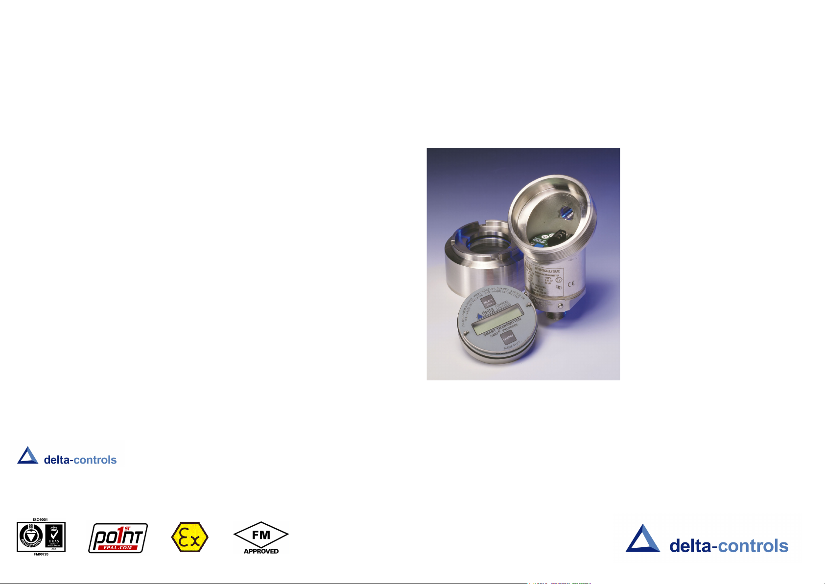
LOCAL CONFIGURATOR INSTALLATION & WIRING
L CAUTION Make sure that the loop is isolated or safe !!
The local configurator / display is connected to the transmitter with a length of ribbon cable which
carries power, display drive and switch signals to the microprocessor. The cable is terminated in
an IDC connector that fits into the header on the top connection board, the plug is keyed to ensure
correct polarisation. PLEASE NOTE the transmitter should have its loop wiring fitted before the
display is connected which will ensure the display cable is not damaged.
When the display is connected the assembly can be pushed into place, check that the 'O' ring is
serviceable and apply light silicon grease if necessary. Engage the display and with firm pressure
on the outside edge push the unit home until the display face is level with the top of the housing.
DO NOT apply pressure to the clear window as you may damage the display.
Once the display unit is fitted the zero and span buttons on the top board are disabled, access to
the zero and span options being made through the menu system :-
{ACCESS 2}, {INPUT},{ZERO KEY} or {SPAN KEY}
[SELECT] Aborts the edit and returns to {FIXLOOP}
[[SELECT]] Performs the [SAVE] function and sets the loop current.
L CAUTION Make sure that the loop is isolated or safe !!
(see Section on ACCESS2 for details)
When necessary the unit may be removed by using the handle provided, with firm pressure and
your thumb on the edge of the housing.
DO NOT ROTATE THE DISPLAY IN -SITU
If the display needs to be rotated for ease of viewing the display unit should be removed and then
re-seated in its new position.
25
6
Page 8

Commands and HART Numbers used by 2HT
1 U M
{ACCESS 2}
(Only user-accessible commands are listed)
Number Class Local Description
0 U V Read Unique Identifier 1
Read Primary Variable
2 U M Read PV Current and Percentage of Range
3 U M Read Dynamic Variables and PV Current
6 U Write Polling Address
12 U V Read Message
13 U V Read Tag, Descriptor, Date
14 U V Read Primary Variable Sensor Information
15 U V Read Primary Variable Output Information
16 U V Read Final Assembly Number
17 U 1 Write Message
18 U 1 Write Tag, Descriptor, Date
34 C 1 Write Primary Variable Damping Value
35 C 1 Write Primary Variable Range Values
36 C 2 Set Primary Variable Upper Range Value
37 C 2 Set Primary Variable Lower Range Value
38 C 1 Reset Configuration Changed Flag
40 C 2 Enter / Exit Fixed PV Current Mode
41 C 1 Perform Transmitter Self Test
42 C 1 Perform Master Reset
43 C 2 Set Primary Variable Zero
44 C 1 Write Primary Variable Units
45 C 2 Trim Primary Variable Current DAC Zero
46 C 2 Trim Primary Variable Current DAC Gain
47 C 1 Write Primary Variable Transfer Function
48 C Read Additional Status
53 C Write Secondary Variable Units (Temperature)
COMMANDS U Universal C Common D Device Specific
LOCAL ACCESS M Monitor V View
(D-CAL) 1 Access Level 1 2 Access Level 2
With the local display fitted, access to the zero and span keys on the top circuit board is
restricted, and their operation is disabled by the software. The two functions are now available
through the menu structure. They may look similar to the trim functions but it must be remembered
they change only the upper and lower range values, which represent the analogue output. The
two keys do not modify the factory calibration.
{ZERO KEY}[SELECT]
This command is the same as pressing the zero key on the top board. The lower range value
(LRV) is set to the applied pressure and is represented by 4 mA.
Before the value is saved, the desired pressure must be applied to the instrument, and allowed
to settle.
{HIT SAVE} will be displayed, there are two choices :-
[SELECT] or To abort and return to the {ZERO KEY} menu.
[CHANGE]
[[SELECT]] Used to store the new lower range value, {SAVED} will be displayed
to show that the command is successful.
{SPAN KEY}[SELECT]
This command is the same as pressing the span key on the top board. The upper range value
(URV) is set to the applied pressure and is represented by 20 mA.
Before the value is saved, the desired pressure must be applied to the instrument, and allowed
to settle.
{HIT SAVE} will be displayed, there are two choices :-
[SELECT] or To abort and return to the {SPAN KEY} menu.
[CHANGE]
[[SELECT] ] Used to store new upper range value, {SAVED} will be
displayed to show that the command is successful.
NB To give a reversed output, apply the higher pressure when the zero key is pressed and vice
versa.
7
24
Page 9

{ACCESS 2}
The (TRIMxxx) functions are used to trim the Lower and Upper Range Values of the analogue to
digital converter (ADC) to an accurately generated, external pressure standard. This is used if the
instrument is found to differ from the site standard, for whatever reason. The command can also
be used to increase the measurement accuracy of a turned down instrument.
{TRIM LRV}[SELECT]
Apply a pressure equal to the LRV pressure (usually, but not necessarily zero!!) to the
instrument, and allowed to settle. NOTE:- the accuracy of the reference pressure should be 3 -
5 times better than the instrument.
{HIT SAVE} will be displayed, there are two choices :-
[SELECT] or [CHANGE] To abort and return to the {TRIM LRV} menu
[[SELECT]] Press and hold for two seconds to store the ADC offset value,
{SAVED} will be displayed to show that the command is successful.
{TRIM URV}[SELECT]
The URV may be trimmed to increase the accuracy of the transmitter when using large
turndowns. Apply a pressure equal to the LRV pressure. NOTE:- the accuracy of the reference
pressure should be 3 - 5 times better than the instrument.
{HIT SAVE} will be displayed, there are two choices :-
[SELECT] or[CHANGE] To abort and return to the {TRIM URV} menu.
[[SELECT]] Press and hold to store the ADC offset value, {SAVED} will be
displayed to show that the command is successful.
Commands and HART Numbers used by 2HT
Number Class Local Description
135 D 1 Restore Factory Defaults
148 D V View Trim settings
149 D 2 Set PV Trim Span
151 D 2 Set Password Access for D-CAL
152 D V View Model Number
COMMANDS U Universal C Common D Device Specific
LOCAL ACCESS M Monitor V View
(D-CAL) 1 Access Level 1 2 Access Level 2
HART Commands
These commands are not supported by the transmitter, but will be decoded when the
SHOWHART command is enabled.
Number Class Description
33 C Read Transmitter Variables
39 C EEprom Control
50 C Read Dynamic Variable Assignments
51 C Write Dynamic Variables Assignments
52 C Set Transmitter Variable Zero
54 C Read Transmitter Variable Information
55 C Write Transmitter Variable Damping Value
56 C Write Transmitter Variable Sensor Serial Number
57 C Read Unit Tag, Descriptor, Date
58 C Write Unit Tag, Descriptor, Date
59 C Write Number of response preambles
108 C Write Burst Mode Command Number
109 C Burst Mode Control
110 C Read All Dynamic Variables
23
8
Page 10

Configuration using the Local Display
{ACCESS 1}
View This menu option is an unprotected level, most of the internal parameters can
Access 1 This is a protected option; a password may be set if required to restrict access
Access 2 This is a protected option; a password maybe set if required to restrict access to
Please Note :- When the transmitter is shipped from Delta the passwords are set to their
If you become locked out a master password maybe issued by Delta but an administration cost
may be charged at their discretion.
Passwords only apply to the D-CAL local configurator. It is assumed that access via a host
computer or a hand-held configurator will be adequately controlled by the system itself or
site access discipline.
be viewed using this selection but no changes can be made. Intended for
recording and logging instrument set-ups.
to the choices within this section. The passwords are set and enabled within
{ACCESS 2}.This menu option contains information that can be viewed, edited
and saved to re-configure the transmitter, using its built-in data as reference.
the choices within this section. This section contains the highest level of menu
options, and consists of choices for commissioning, low level protection and
setting of passwords. It also contains fundamental calibration and setting
procedures which require reference to external standards.
default of {1111} and {2222}, if you edit and save, the new passwords become
the default and stay resident even when loop power is removed.
DO NOT FORGET TO LOG YOUR PASSWORD.
{SHOWHART}[SELECT]
This command, when enabled displays all decoded incoming HART messages by their
number on the display. It may be disabled or left enabled, the default is disabled. The transmitter
will decode all messages that are on the HART bus, and will decide if it needs to reply to them.
SHOWHART will display all messages, even if they are intended for another transmitter,
this allows the digital integrity of the line to be checked.
The command numbers are displayed in monitor mode, and will overwrite the prime
variable display, the numbers can be decoded using the command summary on page 58, this
gives the command numbers available to the transmitter.
The state of the SHOWHART flag is shown, press [CHANGE] until the required state is shown.
There are now two options :[SELECT] Press briefly to abort and return to the
{SHOWHART} menu.
[[SELECT]] Press and hold to save the new state.
9
22
Page 11

{ACCESS 1}
CONFIGURATION USING THE D-CAL
{SELFTEST}[SELECT]
If you suspect the functionality of the transmitter, SELFTEST when passed will give a very high
confidence level of the transmitters output, this is an extension of the tests that the unit performs
on itself at all times.
The screen will blank, test the display, memory, etc. and if all tests pass the unit will respond
{MEM OK}, if a test fails the results will be shown on the screen.
[SELECT] To return to the {SELFTEST} menu.
L CAUTION The transmitter will be off line for 2 seconds, and will respond to HART®
host requests as busy.
{RESET}[SELECT]
This is a master reset of the transmitter, it is equivalent to cycling the power, a SELFTEST is
performed. Please note that the analogue current is set to 4 mA at the beginning of the test.
When [SELECT] is pressed the reset function will begin.
{RESTORE}[SELECT]
The restore command is used to reset the analogue output calibration values which were
established during factory calibration. Please note the URV and LRV, zero and span trims and
analogue trims will be reset.
{HIT SAVE} will be displayed, there are two choices :-
[SELECT] or To abort and return to the {RESTORE} menu.
[CHANGE]
[[SELECT] ] Press and hold to initiate the restore function,
{SAVED} will be displayed...or
[SELECT] Press and release to return to the {RESTORE} menu.
configuration and commissioning. It uses an alphanumeric display so that engineering units and
The local D-CAL Configurator unit gives the operator a user friendly interface for
menu titles may be shown. Wherever possible the HART® functions have been placed in a logical
position within this structure. The two buttons, change and select are used to navigate though the
selections.
MONITOR MODE
When the unit is first turned on the default is monitor mode, the unit will display the Prime
Variable, cycling between the value and the engineering units. Press the [SELECT] button to cycle
through the other displays available.
Primary Variable
This shows the actual pressure (gauge, absolute or differential) that the unit is currently
sensing. The default unit of measurement is the Pascal, from which all other engineering units
are calculated. Each time the selected engineering units for pressure are changed, all values
displayed from the menu system will use these selected units. Note that the displayed value
covers the full range of permitted input pressure, irrespective of the “turndown” selected for
the 4 to 20 mA output.
Loop Current
This displays the current within the control loop. If the loop has been fixed (see
{FIXLOOP}), it will show the fixed value and not reflect the value of the input.
Temperature
This shows the temperature of the sensor. While it is used primarily for the compensation
of the transmitter, it is useful for diagnostics and general information. It is not the temperature
of the process but can give an indication depending upon installation practice.
Percentage
This is the selected output of the transmitter expressed as a percentage. When the
square root function is selected for a flow application, this will therefore show the percentage
of the selected flow range. Engineering units for flow are not available.
{SHOWHART}
If the command {SHOWHART} has been enabled under access level 1, then in monitor
mode, the transmitter will also show any received HART® commands. The command is
displayed as the command number and is automatically cleared after two seconds.
21
10
Page 12

MONITOR and VIEW
DISPLAY
MONITOR PV LOOP CURRENT
SENSOR TEMP
% OUTP UT
{ACCESS 1}
{TAG}[SELECT]
Monitor mode is the default
of the display, it shows prime
variable, loop current and sensor
temperature. Prime variable is always
displayed, cycling between value and
engineering units, this is to allow
engineering units to be shown
without scrolling the display. It is quite
normal for the D-Cal unit to change its
scroll and cycle speed aid clarity at
lower temperatures.
RESTRICTED ACCESS
To gain access to a
restricted level the following steps
should be performed.
{--> 0***} With '0' flashing.
Use the select and change keys to
enter the code number. When the
last digit is selected a decision is
made, if the number is correct the
menu level is entered, other wise the
menu will abort to {ACCESS 1}
If the wrong number is entered
access will be denied.
VIEW
ACCES S 1
ACCES S 2
ACCESS 2
INPUT TRIM LRV
TRIM URV
ZERO KEY
SPAN KEY
ESCA PE
OUTPUT FIX LOO P
TRIM LOOP
ESCA PE
PASSWOR D ACCES S 1
ACCES S 2
ESCA PE
TRIM 4mA
TRIM 20mA
ESCA PE
An eight character alphanumeric field for identification e.g. {TANK6} {LEVEL9}
The tag is displayed on screen, there are two options :-
[SELECT] To abort displayed tag and return to the TRANSMTR menu.
[CHANGE] Used to edit the display. See page 5 ' Display and Edit '
{MESSAGE}[SELECT]
A 32 character alphanumeric field for any information set by site practice e.g..
{CHECKED BY SIMON 29 02 92} or {HIGH PRESSURE SERVICE}
The message is displayed on screen, there are two options :-
[SELECT] To abort displayed message and return to the TRANSMTR menu.
[CHANGE] Used to edit the display. See page 5 ' Display and Edit '
{DESCRIPT}[SELECT]
A 16 character alphanumeric field for additional identification of the transmitter
e.g.. {TANK 6} {LEVEL 9} {UNIT 27} etc.
The Description is displayed on screen, there are two options :-
[SELECT] To abort displayed message and return to the TRANSMTR
menu.
ESCA PE
The access restrictions apply to local configuration only. It is assumed that remote access, via
a portable HART® configurator on a host computer, is adequately access-protected.
11
{DATE}[SELECT]
The date may be the next calibration day, last re-zeroed, according to site practice.
The date is entered in the form DD MM YY
The information is sent digitally in the form MM DD YY.
The date is displayed on screen, there are two options :-
[SELECT] To abort displayed message and return to the TRANSMTR menu.
[CHANGE] Used to edit the display. See page 5 ' Display and Edit '
20
Page 13

(Nb There is no Page 18)
{ACCESS 1}
{OUTPUT}[SELECT]
The transmitter’s analogue output and percentage display may be linear or square root, selected
by this function. The PV display of engineering units is linear at all times. There is no facility for
displaying engineering units of flow. If this is required, then a separate Flow Computer should be
used.
The output function is displayed; there are two options :-
[SELECT] To abort and return to {OUTPUT}.
[CHANGE] Used to edit the display.
{LINEAR} This is the default condition and provides a linear analogue output and
percentage display with reference to applied pressure input.
{SQ ROOT} This applies square root extraction to the analogue output and percentage display
with reference to applied pressure, often used for flow calculation. This is available on pressure
and differential pressure units, as standard software is used for both.
INPUT
OUTPUT
TRAN SMTR
CONTROL
ACCESS 1
PV UN ITS
RANGE HI
RANGE LO
DAMPING
BURNOUT
ESCA PE
LINEAR
SQ ROOT
TA G
MESSAGE
DESCRI PT
DATE
ESCA PE
SELF TEST
RES ET
RESTOR E
SHOWHART
ESCA PE
SELECT
CHANGE
INPUT SENSOR
RANGE HI
OUTPUT
ADDRES STRAN SMTR
MESSAGE
VIEW
RANGE LO
DAMPING
BURNOUT
ESCA PE
TA G
DESCRI PT
DATE
MODEL NO
PRVT LAB
DEV ID
VERSION
ESCA PE
SER NO
HI LIMIT
LO LIMIT
MIN SPAN
ESCA PE
19
ESCA PE
ESCA PE
Both Access 1 and Access 2 can be protected by passwords. Before they are enabled, it is
recommended that you read the section on Passwords. The D-CAL unit will default to Monitor
Mode if there are no keystrokes for five minutes.
12
Page 14

{VIEW}
The view menu is not protected by a password, as no changes can be made from within this menu
option. After five minutes it will return to the monitor mode.
{INPUT} [SELECT] Enter the input menu
{SENSOR} [SELECT] Enter the sensor menu
{SER NO} [SELECT] Show the sensor serial number, in decimal
{HILIMIT} [SELECT] Show the sensor URL in engineering units
{LOLIMIT} [SELECT] Show the sensor LRL in engineering units
{MINSPAN} [SELECT] Show the sensor’s minimum available span, If
{RANGEHI} [SELECT] Show, in engineering units, the transmitter URV
{RANGELO} [SELECT] Show, in engineering units, the sensor LRV
{DAMPING} [SELECT] Show the damping value in seconds. This is
{BURNOUT} [SELECT] This shows which direction the analogue output
Pressing {CHANGE} wil move down through the menu.
At the end of each sub-menu, select {ESCAPE} to return to the higher menu.
this is exceeded when using turndowns greater
than 20 to 1 an error will be reported.
corresponding to 20 mA
corresponding to 4 mA.
applied to the analogue and digital output
signals.
will go in event of a fatal sensor failure.
13
18
Page 15

{INPUT} continued
{ACCESS 1}
{VIEW}
{OUTPUT} [SELECT] This shows the function that is applied to the
analogue output. The options are {LINEAR} AND
{SQ ROOT}
{DAMPING}[SELECT]
The damping command is used to slow the rate of change of the output signal, it modifies both
the analogue and digital signal.
The damping value is displayed in seconds, there are two option :-
[SELECT] To abort displayed tag and return to {DAMPING} menu.
[CHANGE] Used to edit the display.
Damping uses a fixed template and will accept values between 0 and 39 seconds.
{BURNOUT}
Burnout is used to sense a failure of the sensing element. It drives the analogue output either
upscale or downscale depending upon its setting.
Once select is pressed the state of the burnout flag is shown either upscale or downscale. Press
[CHANGE] until the desired state is shown.
There are now two options :-
[SELECT] To abort and return to the {BURNOUT} menu.
[[SELECT] ] Press and hold to save the new state.
Pressing {CHANGE} wil move down through the menu.
At the end of each sub-menu, select {ESCAPE} to return to the higher menu.
{TRANSMTR}
{ADDRESS}
{TAG} [SELECT] Shows the tag, 8 characters.
{MESSAGE} [SELECT] Shows the message, 32 characters.
{DESCRIPT} [SELECT] Shows the description, 16 characters.
{DATE} [SELECT] Shows the date. When using the HART® format
{PRVT LAB} [SELECT] This shows the distributors number if the
{DEV ID} [SELECT] This shows the device identification number in
[SELECT] Enter the Transmitter menu
[SELECT] Shows the polling address of the instrument, 0 for
point to point, 1 -15 for multi-drop. If the value is set
from 1 - 15 the analogue value is set to 4 mA.
for remote communications the date is transmitted
as MM DD YY format. On the display it is shown
as DD MM YY
instrument is being sold under a badging
agreement, see HART® common tables
decimal, this is combined with the manufacturers
id and device type
(Nb There is no Page 18)
17
{VERSION} [SELECT] The software version, original manufacturer and
copyright notice will be displayed.
14
Page 16

{ACCESS 1}
{ACCESS 1}
{INPUT} [SELECT]
{PV UNITS}[SELECT]
Because the measured pressure is converted to a digital number the way the number
is displayed can be scaled to represent different engineering units, this affects the digital and
local display signals.
The prime variable (PV) units of measure are displayed, there are two choices :-
[SELECT] To abort and return to the {OUTPUT} menu.
[CHANGE] Used to change the units of measure. There are set choices of units dependent
upon which output function is enabled.
LINEAR & SQUARE ROOT
{ InH20 }
{ InHG }
{ FtH20 }
{ mmH20 }
{ mmHG }
{ PSI }
{ Bar }
{ mBar
{ Gm/SQcm }
{ KG/SQcm }
{ PaScal }
{ KPaScal }
{Torr }
{ Atm }
Once the required units are displayed they can be selected and saved [[SELECT]]
or [SELECT] to abort to the {PV UNITS} menu.
{INPUT} continued
{RANGEHI}[SELECT]
This is the pressure represented by 20 mA and may be less than range low to achieve reverse
action of the analogue output. This allows the analogue output of the transmitter to be re-ranged
without using a reference. It also sets a value to which { TRIM URV } will be set
under {ACCESS2}, below.
The URV is displayed followed by the engineering units there are two options :-
[SELECT] To abort displayed tag and return to {RANGEHI} menu.
[CHANGE] Used to edit the display.
The edit featu re does not use a template because the values are entered in the current
engineering units. The screen is blank with a flashing {+} sign, work along the display entering
the value, use the character after {9} to depict a decimal point.
When the last character is reached [[SELECT]] will save the value and 20 mA will now represent
this new pressure on the analogue loop.
{RANGELO}[SELECT]
This is the pressure represented by 4 mA and may be greater than range high to achieve reverse
action of the analogue output. This allows the analogue output of the transmitter to be re-ranged
without using a reference. It also sets a value to which { TRIM LRV } will be set under
{ACCESS2}, below.
The display, options and edit features are the same as for RANGEHI.
This pressure will now be represented by 4 mA on the analogue loop.
Any change to the prime variable units will change all engineering units that are displayed,
upper and lower range limits, upper and lower range values and alarms.
The display may need to scroll to display the longer engineering units.
15
Pressing {CHANGE} will move down through the menu.
At the end of each sub-menu, select {ESCAPE} to return to the higher menu.
16
 Loading...