

Page 1

Smart 2HT transmitter
Issue Feb 10
How can we help you?
Technical Datasheets and IOM Instructions for all
Delta Controls' pressure and temperature
measurement products are available from our
website at www.delta-controls.com.
For Service and Repair enquiries, please contact the
Sales Engineering Teams on +44 (0)20 8939 3500
or email sales@delta-controls.com.
Delta Controls Limited
Island Farm Avenue, West Molesey, Surrey KT8 2UZ, UK
T +44 (0) 20 8939 3500 F +44 (0) 20 8783 1163 E sales@delta-controls.com W www.delta-controls.com
002522-2HT 180210.doc
1
Page 2

CONTENTS
Warranty - - - - - - - - 3
Glossary - - - - - - - - 3 - 4
Product Introduction - - - - - - - - 5
Features
Sensor, Electronics - - - - - - - - 5
Software & Local Display - - - - - - - - 5 - 6
Installation
General - - - - - - - - 6
Mechanical - - - - - - - - 7
Electrical - - - - - - - - 7 - 9
Commissioning
Blind Instrument - - - - - - - - 9 -10
Multi-Drop - - - - - - - - 11
Trouble Shooting - - - - - - - - 11
Specifications - - - - - - - -
Functional, Performance 12
Physical & Drawings - - - - - - - - 13
Certified Products - - - - - - - - 14-15
Options, Spares and Maintenance - - - - - - - - 16
Re-Calibration Procedure - - - - - - - - 16
Product code - - - - - - - - 17
002522-2HT 180210.doc
2
Page 3

WARRANTY
This instrument is guaranteed against faulty workmanship and material for a period of one year from the
date of delivery. The company undertakes to repair, free of charge, ex-works any instrument found to be
defective within the specified period provided the instrument has been used within the specification in
accordance with these instructions and has not been misused in any way. Detailed notice of such defects
and satisfactory proof thereof must be given to the company immediately after the discovery and the
goods have to be returned free of charge to the company, carefully packed and accompanied by a
detailed failure report.
HEALTH AND SAFETY
To comply with health and safety requirements, any returned instrument must be clean and safe to
handle and accompanied by a formal statement to that effect duly signed by an authorised officer of the
user company. Any instrument returned without certification will be quarantined and no action will occur
until cleared. We reserve the right to refuse to handle, and to return to the user, subject to transportation
charge, any instrument for which a declaration of safety is not received.
COPYRIGHT
Copyright © 1994 - 2007 Delta Controls Limited. All rights reserved. No part of this publication may be
reproduced, stored in a retrieval system or transmitted in any form or by any means without the express
prior written permission of Delta Controls Limited.
Copyright © 1994 - 2007 Delta Controls Limited. All rights reserved. All software and firmware supplied
with this instrument, on disc or embedded are the sole property of Delta Controls Limited.
DISCLAIMER
Delta Controls Limited does not authorise or warrant any product for use in life support devices and/or
systems without the express written approval of an officer of the Company. All information contained
within this manual is provided in good faith as a guide only; for specific applications, Delta Controls
Limited should be contacted directly. The information contained within this manual is subject to change
without notice.
NOTE
HART® is a registered trademark of the HART Communication Foundation.
Hastelloy C® is a registered trademark of Cabot Corporation.
Monel® is a registered trademark of International Nickel Co.
GLOSSARY
Characterise Factory procedure used to calibrate the electronics so that sensor errors and
Configurators To take advantage of the extra features within a smart transmitter a "configurator" is
Damping Software function used to increase the response time of the transmitters analogue
Descriptor A sixteen character field for additional identification of the field device, this may
EEPROM Electrically erasable programmable read only memory, that retains its memory even
EMC Electro Magnetic Compatibility, the ability of a product to function without influencing
HART® Highway Addressable Remote Transducer. This protocol has become the de facto
temperature shifts are eliminated.
used. This normally allows viewing and editing of variables via a keyboard and
integral display.
output. This helps to smooth the output when there are rapid input variations.
contain its plant location, or name.
during long term power removal
any other product, or being influenced
standard for digital communications with smart field devices. The HART®
Communications Foundation is the owner of the registered trademark and provides
support for end users and developers.
002522-2HT 180210.doc
3
Page 4

LRL Lower Range Limit (pressure): The lowest measured value (pressure) that the
transmitter can sense, governed by the sensor.
LRV Lower Range Value (pressure): Normally the lowest measured value (pressure) that
the analogue output (mA) of the transmitter can represent, but this may be reversed
with URV (pressure) for reverse analogue outputs (mA).
Master Name used to describe any system that is in control of the slave field devices, HART
can support two masters, primary and secondary.
Message A thirty two character field for additional information, name of installation engineer,
calibration technician etc.
MODEM Modulator \ Demodulator: a device that converts serial computer signals to and from
an FSK (Frequency-Shift-Keyed) format.
Multidrop This mode allows several field devices to share a common twisted pair of cables, a
total of 15 devices may use one cable.
Polling Address Unique number (1 - 15) used to identify an instrument when it is used in a multi-drop
circuit. Transmitters that are not used in a multi-drop configuration have a poll number
of zero.
Protocol A set of rules or specifications that defines the structure of a communications
language.
PV Prime Variable, in this case pressure.
Re-ranging Function that allows the transmitters analogue output to be scaled differently from the
sensors upper and lower range limits (pressure).
SV Secondary Variable, in this case temperature.
Slave Name used to describe any device that will respond when requested to by a master.
Smart A generic name used to describe any field device that can be configured from a
remote location, and shows some form of intelligence.
Span Difference between the upper and lower range values (pressure).
Sputtering A process used to bond glass and other materials to each other at a molecular level.
Tag An eight character field for identification of the transmitter, this is used in long frame
format to build the unique identifier
URL Upper Range Limit (pressure): The highest measured value (pressure) that the
transmitter can sense, governed by the sensor.
URV Upper Range Value (pressure): Normally the highest measured value (pressure) that
the analogue output (mA) of the transmitter can represent, but this may be reversed
with LRV (pressure) for reversed analogue outputs( mA).
002522-2HT 180210.doc
4
Page 5

PRODUCT INTRODUCTION
The Delta HT Series of SMART transmitters accurately measures gauge or absolute pressure and
transmits a traditional 4-20 mA signal as well as a digital signal using the HART® protocol. The HART®
protocol gives the ability to integrate into one system, products from different manufacturers with
predictable functionality and control. HART® has become the most widely used digital communication
system for process instruments and controllers.
These transmitters complement the popular Delta 387 transmitters. Digital technology has been used to
ensure accuracy, stability and range-ability across the full temperature range. Like its smaller brother the
HT series of transmitters features a robust all stainless steel case.
The extensive use of surface-mount components and custom micro-power devices has resulted in a
transmitter that is small, light and self supporting, although pipe mounting brackets are available if
required.
In addition to the remote digital communications, the unit has, as standard, local zero and span
adjustment at the touch of a button. If more than just local span and zero are required, there is a local
display module available, the D-CAL. This can directly access more than 80% of the SMART
transmitter’s commands, for installation, commissioning and maintenance checks. The display may be
fitted within the unit with no change to the external dimensions or supplied in a small hand-held case for
repeated use when configuring blind instruments.
The transmitter is manufactured within a quality system, approved to ISO 9001:2000.
FEATURES
THE SENSOR :-
Gauge and Absolute Pressure - The preferred sensor below 10 Bar is a precision piezo-resistive
transducer, with a silicone fill and a 316 stainless steel diaphragm. Above 10 Bar the sensor is a one
piece, machined diaphragm with a sputtered thin film strain gauge. The diaphragm is specially designed
to optimise the sensor for each range. The wetted parts of the sensor (diaphragm and inlet) can be
selected from stainless steel, Monel or Hastelloy C to suit the process fluid being used. Gauge or
absolute reference can be offered on all ranges.
THE ELECTRONICS :-
The heart of the HT transmitter is an electronics module that uses surface mount technology
and a 16 bit micro-controller, supervising all functions of the transmitter and performing
continuous self checks to make sure the software is running properly.
The micro-controller takes the digital output from the sensor electronics and, using calibration
coefficients, compensates the sensor signal for linearity and local temperature. Because the actual
pressure is now digitised, any mathematical function may be applied to change the output. This allows
conversion between different engineering units to be shown and square root extraction to be applied
where required.
Any changes to the transmitter configuration are stored in EEPROM which is non volatile in the event of
power supply failure. If a power failure occurs the transmitter will restart safely and signal digitally to a
controller that a power failure has occurred.
The digital, linearised signal is fed to the output circuits. One signal is converted into a 4 to 20 mA
current, the other is a superimposed audio tone conforming to the HART® protocol.
The input and output circuits of the transmitter are fully protected against over voltage, reverse polarity
and RFI ; the local display/configurator is IP rated and protected against RFI.
THE SOFTWARE :-
The software controls all functions of the transmitter, continuous self-diagnostics, communications,
pressure calculations and display (if fitted). The firmware program is permanently stored within the
micro-controller, all calibration and run time variables are stored in EEPROM. The software has built-in
checks for sensor failure, loss of voltage reference and many other very unlikely failures. The software
also contains complex algorithms for temperature and sensor linearisation, to mathematically
characterises the sensor and electronics over its full temperature range to guarantee accuracy and
repeatability. Within the software there is also a powerful state machine which is the set of statements
that make decisions within the local configurator, and allows the transmitter to be set up as required.
002522-2HT 180210.doc
5
Page 6

THE DISPLAY / CONFIGURATOR (“D_CAL”) :-
The Local display unit is constructed from a single stainless steel puck that when fitted gives the
transmitter a protection rating of IP 54 with the cover removed. The unit continuously shows prime
variable and units of measure in monitor mode. If current or percentage output is required, then this may
be selected on the D-CAL. The display unit also allows access to the state machine that generates a
user friendly menu with access to the internal HART® functions that are commonly used for installation
and maintenance.
To browse, edit and store information from the menu two buttons are used, CHANGE and SELECT. The
SELECT button, when held for 2 seconds, saves a selected value to EEPROM. If the selection is invalid
or out of range the transmitter will not store the change and will reply {REJECTED}.
For full detail, see the D-CAL Manual
INSTALLATION ( GENERAL )
The final accuracy of the transmitter depends to a great
extent on the proper installation of the unit and impulse
piping. Care should be taken to minimise the effects of
vibration, shock and temperature fluctuations. Care
should also be taken to make sure that the transmitter is
in a accessible position, where possible.
Before installation of the unit, ensure that the pressure
range and maximum working pressures selected are
compatible with the expected system pressure. Adequate
lengths of impulse lines, or siphons should be used to
ensure that very high temperature process media do not
come into direct contact with the unit. Precautions should
also be taken against the media freezing within the unit.
As the best location for the transmitter in relation to the process depends upon the process medium,
please consider the following points before installation.
• Keep all impulse lines as short as possible, and of the same length.
• Avoid high points in liquid and low points in gas lines.
• Use piping large enough to prevent blockage.
• Make sure there are no unaccounted static heads that will give false readings.
• Make sure that the transmitter is isolated from high process temperatures.
The 2HT is designed to be self supporting and can be mounted in any position. Brackets are, however,
available should wall or pipe mounting be required.
The pressure connection should be tightened using a 50 mm ( 2" ) AF spanner on the flats of the lower
body, and the appropriate spanner on the pipe-work connector.
DO NOT USE A COMPRESSION WRENCH ON THE 2HT BODY TO TIGHTEN THE PRESSURE
CONNECTION.
Typical Pipe Mounts for 2HT
002522-2HT 180210.doc
6
Page 7

MECHANICAL INSTALLATION
Conduit connection
The 2HT series Transmitters are supplied with either M20 x 1.5 or 1/2" NPT internally threaded electrical
connection. To prevent condensation build-up in the conduit entering the instrument housing, the
following piping layout should be followed. Additional considerations must be made if transmitters are to
be mounted in hazardous areas.
If cable is used a suitable gland should be chosen so that protection rating and hazardous area
certification is not affected, in accordance with site or national codes of practice.
ELECTRICAL INSTALLATION
Cable selection
The HART protocol is designed to be used over conventional instrument cables, but there are limitations
on the usable length, depending on the type of cable used. These limitation are concerned with two
things :-
(i) keeping interference at a level low enough not to affect the reliability of the communication, and
(ii) ensuring a proper signal level at the receiver.
Interference.
Each HART loop consists of a pair of wires, these should be twisted together to reduce interference
from external electromagnetic fields. Please note that the full benefit of a twisted pair is not obtained
because the HART signal is not symmetrically balanced on the two wires. For all but the very shortest
cable runs, screening is necessary for protection against interference. There may be a single screen
covering a number of twisted cables, or, better, each twisted pair may have its own individual screen. All
screens should be connected together and connected to ground at one point only, typically near the
control room.
Signal Level
The main factor that affects the signal level is cable capacitance. The signal level is degraded as the
cable capacitance rises. As a general rule the product of the total resistance and the total capacitance
must be less than 65 microseconds.
Cable capacitance is measured per meter so multiply the nominal value by the length of cable run. For
each HART device allow 5 nF x the CN number.
To limit the possible effects of interference and signal degradation the following rules are imposed in the
HART specification :-
Maximum overall length, individually screened pairs :- 3000 metres
Maximum length, multiple pairs with only an overall screen :- 1500 metres
( Rload + Rbarrier + Rmiscellaneous ) ohms x ( Ccable + Cdevices ) farads <= 65uS
002522-2HT 180210.doc
7
Page 8

Do not mix non-HART compatible signals within the same cable run.
Cable should be run through a sealed metal gland rated IP66, to avoid moisture ingress in to the
housing and provide a strong mechanical fixing. For EEx d applications the use of approved cable and
glands is a mandatory requirement
Recommended wiring practice
It is recommended that the field wiring be trimmed to length
as follows. This will then allow access to the zero and span
buttons and prevent fouling of the display cable if fitted.
Recommendations for Power supply :-
The DC power supply should have less than 2% ripple, and be able to source at least 24 mA for a single
transmitter and 100 mA for a multi-drop system, at a nominal 24 volts.
RECEIVER PSU
+
-
250
ohm
ADDITIONAL INSTRUMENTS
The terminal block inside the instrument has three connections, signal, return and ground. For
convenience there is an internal ground as well as two external connections.
The Delta transmitter will run with reverse polarity and has over voltage protection as standard.
GND
INTERNAL
CASE
GROUND
7mm
+VE
-VE
30mm
45mm
60mm
GND
002522-2HT 180210.doc
8
Page 9
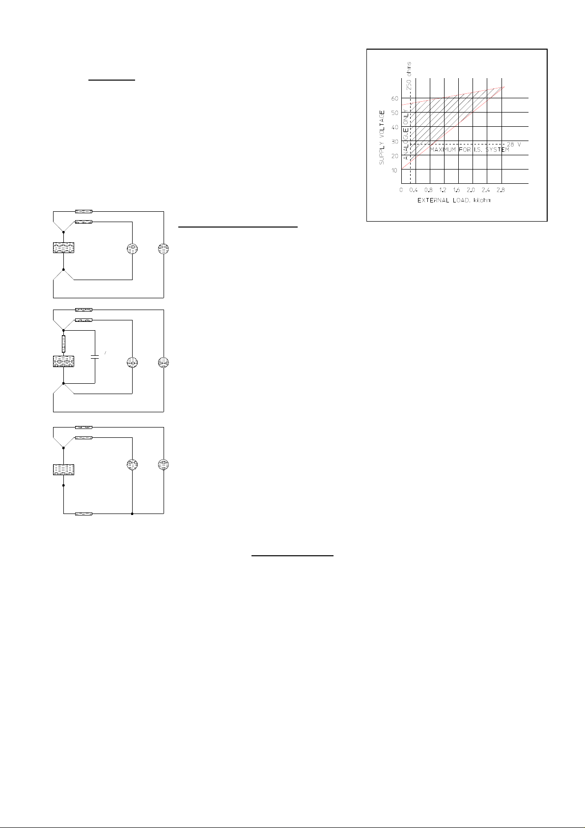
Loop load
The required loop voltage is based on the loop resistance. To
determine the total resistance, add the resistance of all the units
within the loop (except the transmitter). The required supply
voltage can be determined by reference to the graph. Note that
there must be a minimum of 250 ohms within the loop for digital
communication to take place.
RL 2
RL 1
+VE
PSU
0 V
Tx 1 Tx 2
Factors to be considered.
The ideal system with no cross-talk, this assumes that the PSU has zero
impedance at the HART signalling frequencies. Note that separate positive and
ground lines are run to each instrument. Cables are spaced, or screened, to
prevent capacitive coupling between loops.
RL 2
RL 1
+VE
RS
PSU
0 V
10000 uF
Tx 1 Tx 2
The HART protocol requires the PSU series resistance ( RS ) to be less than 10
ohms. Most power supplies will meet this requirement, but with the addition of
distribution wiring and in line fuses care must be taken. If required a 10000 uF
electrolytic capacitor of suitable working voltage may be connected across the
common terminals for the HART loop.
RL 2
RL 1
+VE
PSU
0 V
RC
Tx 1 Tx 2
Common resistance (RC) this can be caused by high cable resistance, or by
grounding multiple loops in the field rather than in the control room. To prevent
high cable resistance resulting from grounding null loop, each loop wire should
be wired back to the psu.
COMMISSIONING
The Commissioning and Transmitter Function sections of this manual assumes a blind instrument or
one fitted with a DELTA local display Configurator. Blind instruments can be re-ranged and zeroed as
standard, using the one touch Zero and Span Buttons.
When the transmitter is shipped it has a fixed upper and lower range limit (URL, LRL) that is dictated by
the sensor used. The upper and lower range values can be set, (URV, LRV) to any value from LRL to
URL so long as the minimum span is not breached. The URV can be set lower than the LRV this will
reverse the transmitter’s analogue output, and give a 20 to 4 mA output.
The engineering units that are displayed and transmitted by the unit may be changed.
There are four ways to re-range the transmitter, each one makes changes to the setting of the URV and
LRV.
1 :- With the zero and span buttons that are fitted on a blind instrument.
2 :- Enter a URV and LRV directly from the “DCAL” configurator (D-CAL).
3 :- Use the Zero and Span options from the local display.
4 :- Using a Universal Hand-held communicator (e.g. Rosemount 375)
002522-2HT 180210.doc
9
Page 10

Re-ranging using the Zero and Span Buttons, Blind Instrument.
The transmitter can have its LRV and URV set using the local keys mounted on the top circuit board. To
set these values a pressure source should be used that has a calibrated accuracy three to five times
better than the desired instrument accuracy, a loop current indicator is also required. Alternatively the
instrument can use the process to generate the required pressures.
1 :- Apply the LRV pressure to the instrument.
2 :- Wait 20 seconds, for the pressure to stabilise.
3 :- Press the [ZERO] button and hold it for 3 seconds.
4 :- Check the loop current equals 4 mA.
5 :- Apply the URV pressure to the instrument.
6 :- Wait 20 seconds, for the pressure to stabilise.
7 :- Press the [SPAN] button and hold it for 3 seconds.
8 :- Check the loop current equals 20 mA.
For reversed analogue output the zero and span buttons are pushed in the reverse order, swap over
commands 3 and 7. To initially reverse the current output it will be necessary to set the zero (LRV) to at
least 5% of the instrument’s full range so that when the span key is pressed the change is not rejected
by the minimum span limit.
Note: the lower and upper range values must fall within the lower and upper range limits, and meet the
minimum and maximum span specifications allowed by the transmitter, if they do not the zero or span
will not be set.
Zero, Span and Rangeability
Forward Action, 4 to 20 mA
Apply the lower range value. This may be achieved once the unit is
installed, or in the workshop with a pressure source. Allow the unit to
settle. Press and hold the zero key for two seconds. 4 mA output will
be set.
Apply the upper range value. Allow the unit to settle, press and hold
the span key for two seconds. 20 mA output will be set.
If the unit is being re-ranged rather than being trimmed the zero may
need to be checked to achieve full accuracy.
Reverse Action, 20 to 4 mA
Apply the lower range value. This may be achieved once the unit is
installed, or in the workshop with a pressure source. Allow the unit to
settle. Press and hold the span key for two seconds. 20 mA output
will be set.
Apply the upper range value. Allow the unit to settle press and hold
the zero key for two seconds. 4 mA output will be set.
If the unit is being re-ranged rather than being trimmed the zero may
need to be checked to achieve full accuracy.
These buttons are automatically disabled when the DCAL is
plugged in via its 10-way IDC connector. They may also be
remotely disabled over the HART® network.
002522-2HT 180210.doc
10
Page 11

MULTI-DROP CONFIGURATION
Multi-dropping transmitters refers to the practice of connecting several units to a single transmission
line. The analogue signal is switched to 4 mA on all units and communication takes place digitally only.
Each message is sent with a unique number that identifies the field device.
The HART® system limits the number of instruments that can be connected in this way to 15. For
Intrinsically Safe installations, maximum permissible circuit current reduces the limit to four. When a
multi-drop system is designed, consideration must be given to the length of transmission line, update
rate required from each transmitter and total power requirement. Multi-drop systems are not
recommended for Intrinsically Safe installations. Each transmitter is identified by a unique number from
1 to 15 and responds to HART® commands that are sent to that address.
Note that the transmitter is sent from the factory with its address set to 0 this disables multi-drop and
allows 4 to 20 mA and digital communication only.
There is no way to change the polling locally. This is for safety reasons, so that the address can only
be changed once digital communication has been established from Hart master.
The use of a separate HART® Multiplexer is permissible, but outside the scope of this manual.
TROUBLE SHOOTING
The integrity of a HART® loop can be validated using several methods, if a local display is fitted the
{SHOWHART}, {FIXLOOP} and {SELFTEST} methods provide a high level of confidence, for lower level
testing or if a local display is not present the use of a simple oscilloscope and voltmeter can be used.
Note: in an Intrinsically Safe application restrictions may apply to the instruments being used.
Analogue Loop Tests.
Is the voltage at the instrument, across the terminals, above the lift-off voltage of the instrument,
typically 9 to 12 volts, see the functional specifications?
Measure the DC voltage across the load resistor, derive the loop current using the calculation :Loop Current = DC Voltage / Load Resistor
This should be between 4 and 20 mA and representative of the measured prime variable, unless the
device is in multi-drop mode where the current will approximately equal 4 mA multiplied by the number
of devices within the loop.
Is the loop grounded properly, normally in one place, at the power supply?
Is the screen of the cable grounded at one end only, normally at the control room?
Are the cables isolated from other high current cables?
Is the cable of the correct grade and not to long, see cable selection and signal level?
Are the barriers HART compliant and is the power supply low impedance?
002522-2HT 180210.doc
11
Page 12

FUNCTIONAL SPECIFICATIONS
Service :- Liquid, Gas or Vapour
Ranges :- 0 ~ 1 to 0 ~ 1000 Bar
( 0 ~ 16 to 0 ~ 16,000 psi )
Sensor Limits:- 2 * URL Overpressure Stainless Steels except range GA, 0
to 1000 bar = 1.5 * URL
1.5 * URL Overpressure Monel & Hastelloy
Output :- 4 to 20 mA DC 2 Wire System with digital AC signal
superimposed on to it, using the HART protocol.
Power Supply :-
Load Limits :- Dependent upon installation and PSU, See chart in Electrical
Hazardous Area
Certifications :Zero Elevation &
Suppression:-
Normal or Reverse
action :Temperature Limits:- Operating :- -40 to +85 Degrees C
Failure Mode
Alarms:Humidity Limits :- 0 to 100% RH
Turn-on Time :- Less than 6 Seconds, This includes full self diagnostics
Volumetric
Displacement :Damping :- 0 to 39 Seconds, in addition to the sensor response time.
9 to 55 Volts DC (Subject to 28 V maximum on Intrinsically
Safe installations)
Installation
See Certified Products
Can be set anywhere within the sensor limits as long as the
span is greater or equal to the minimum span, and URV does
not exceed URL
Set by reversing the upper and lower range values. See
Zero, Span and Rangeability
Storage :- -50 to +110 Degrees C
Display :- -30 to +80 Degrees C
High or Low (Analogue) for a major transmitter malfunction.
< 1 microlitre
PERFORMANCE SPECIFICATIONS
Accuracy
Stability
Temperature Effect
Overrange Effect
Power Up
Vibration Effect
Power Supply
Effect
Mounting Position
Effect
RFI Effects
For spans of 1 : 1 to 10 : 1
+/- 0.1 % of SPAN, Including Linearity, Hysteresis and
Repeatability
For spans below 10 : 1
+/-0.15 % of SPAN
Typically less than 0.15 % URL per annum
Total effect +/- 0.10 % at Max. Span over ambient range
Zero shift, 0.2 % of URL
Less than 6 seconds, including Diagnostics, Display and
Memory tests
5 g Peak sinusoidal at 5 Hz to 200 Hz without deleterious
effect
<0.005% of URL per volt
Zero shift, less than 10 mm H2O for a 10° tilt in any plane.
With the cover on and/or display in place, in accordance
with IEC 6100-4-3, 80 Hz to 1 Ghz at 10 V/m, 1 GHz to 2.7
GHz at 3 V/m. See Declaration of Conformity for the EMC
Directive 89/336/EEC. For full compliance with
susceptibility performance, the screen of the cable must be
directly connected to the enclosure via a cable gland that
makes a 360o connection.
002522-2HT 180210.doc
12
Page 13

PHYSICAL SPECIFICATIONS
Electrical connections :- Female M20 x 1.5 or Female ½ " NPT
Process Connection :- ½ " NPT External, G ½ " A to ISO 228 or
High Pressure Cone and Thread ("Autoclave")
Process Wetted Parts :- Below 10 Bar 316 St. St. inlet and Diaphragm
316 St. St. inlet with 17-4PH or 15-5PH Diaphragm
as standard; Monel and Hastelloy available.
Non- Wetted Parts :- Lower body, Case & Lid :- 316 Stainless Steel
Mounting Hardware :- 316 Stainless Steel
Protection :- IP 66
Mounting :- Direct process mounting as standard.
On 50 mm dia. ( 2" ) pipe using mounting bracket kit.
Wall mounting with kit.
Weight :- 1.6 kg ( 3.5 lb) Blind Instrument
Display, add 200 grams ( 0.44 lb )
95mm
DIAMETER
96mm
ELECTRICAL ENTRY
M20 x 1.5 INT. OR AS
SPECIFIED
Approximate
60mm
DIAMETER
PROCESS ENTRY
1/2" NPT EXT. OR AS
SPECIFIED
m
m
0
5
1
m
m
6
9
Dimensions are
WEATHERPROOF
Models A2HT, R2HT, F2HT, 42HT
The instruments have been tested for dust and water penetration to EN 60529 and have been rated
IP66 with cover in place and conduit entry suitably sealed. Third party test report for water available on
request.
In addition, the instruments, when fitted with the built-in D-CAL configurator, meet IP54 requirements,
enabling configuration to be performed under damp conditions. DO NOT LEAVE INSTRUMENTS
OPEN UNNECESSARILY!
002522-2HT 180210.doc
13
Page 14

CERTIFIED PRODUCTS
FLAMEPROOF
EEx d :- Model R2HT
Apparatus Certificate Number :- ITS03ATEX11187
Compliance with EN 50014:1997, EN 50018:2000 II 2 G. See Declaration of Conformity for ATEX.
EExd IIC T4 (Tamb = -40 to +85°C)
EExd IIC T6 (Tamb = -40 to +60°C)
Note:
Flameproof model R2HT with display fitted (see page 17, signal input code 2 or B) gas group reduced
to II B+ H
2
EExd IIB+H2 T4 (Tamb = -40 to +85°C)
EExd IIB+ H2 T6 (Tamb = -40 to +60°C)
INTRINSICALLY SAFE
Ex ia Approval :- Model 42HT
Apparatus Certificate Number :- ITS03ATEX21213X
EN 60079-0:2006, EN 60079-11:2007, EN 60079-26:2007
Ga Ex ia IIC T4 (T
Conformity for ATEX.
Safety Parameters :- Ui = 30 Volts
Ii = 130.9 mA
Pi = 0.66 Watts
Li = 30 uH
Ci = 16 nF
Special Conditions :-
1. The pressure transmitter may be fitted with an integral display or alternatively, when the blanking
plate is removed, a hand held display may be inserted into the socket provided. The removal of the
blanking cover is only permitted in a non-hazardous area.
2. The pressure transmitters intended for operation at 50 V dc do not meet the requirements of EN
50020:2002 clause 6.4.12 (Electrical Strength Test). This shall be taken into account when
installing the apparatus in a potentially explosive atmosphere.
–20 to 80oC) II 1 G See Declaration of
amb
SYSTEM
The user/installer is responsible for ensuring the safety parameters of the circuit/system are not
exceeded. Refer to IEC 60079 -14: Electrical apparatus for explosive gas atmospheres - Electrical
installations in hazardous areas (other than mines) and EN 60079 –25: Electrical apparatus for
explosive gas atmospheres - intrinsically safe systems
USA EXPLOSIONPROOF AND INTRINSICALLY SAFE
FM:- Model F2HT
F2HT Report Number 1B5A6.AE
Approved for Explosionproof Class I, Division 1, Groups B C & D
Dust-Ignition-Proof Class II/III, Division 1, Groups E F & G
Intrinsically Safe Class I, II, III Division 1, Groups A B C D E F & G
(
Entity requirements, Control Drawing No 2/14307, Entity Parameters: V Max =30 V, I Max = 130.9 mA, Ci = 8.85 nF,
Li = 30 µH, P Max = 0.67 W)
NEMA 4X
002522-2HT 180210.doc
14
Page 15

002522-2HT 180210.doc
15
Page 16

OPTIONS
Mounting Stainless steel wall and pipe clamps are available as an optional way of
mounting the unit.
Display / Configurator The D-CAL configurator / display may be ordered with the transmitter or
retrofit at a later date, without compromise to the certifications. This unit is
not loop powered and can only be used with the Delta Controls HT range of
SMART Transmitters.
SPARES
Lid 'O' Ring :- Spares No. 155042
Display 'O' Ring :- Spares No. 155043
Display Overlay :- Spares No. 9020311
Lid ( Free Blank ) :- Spares No. 9420004
Lid ( Free Windowed ) :- Spares No. 9400123
Display Assembly :- Spares No. 9400124
MAINTENANCE
The unit requires no maintenance as standard, but it is recommended that all cable terminals be
checked for tightness at standard site maintenance intervals. Please note that all of the circuit boards
within the unit are protected against water damage so it is unnecessary to apply any other form of
protection, as this may void the products warranty.
RE-CALIBRATION
The 2HT series instruments are designed for long and stable lifetime operation.
The nature of a combined analogue / digital instrument such as this, is that the Analogue to Digital
Converter that processes the sensor input measures the total permitted pressure range of the
instrument, irrespective of the chosen output of the 4 to 20 mA range. Changes in the selected
4 to 20 mA output are made against the stored, compensated values of pressure conversion.
From time to time, however, it will be necessary to check, and, if required, trim the scaling of the A-D
converter against a local pressure standard.
The method used by the 2HT series, assumes that the two most important calibration points for the
chosen application are the Lower and Upper Range Values set for the 4 to 20 mA output. These, not
the instrument’s zero and nominal Upper Range Limit, are the values to be applied to the instrument
when trimming the ADC.
Apparatus Needed
A accurate pressure supply (+/- 0.03% of value)
A Delta D-CAL Communicator (as the procedure requires a Device Specific command, only software
versions 5.00 and later may be trimmed via HART® )
Method
Apply a pressure value equal to the instrument’s selected Lower Range Value. In the ACCESS2 menu
of the D-CAL, go to {TRIM LRV}[SELECT]
{HIT SAVE} will be displayed, there are two choices :[SELECT] or [CHANGE] To abort and return to the {TRIM LRV} menu
[[SELECT]] Press and hold for two seconds to store the ADC offset value, {SAVED} will be
displayed to show that the command is successful.
Now apply a pressure value equal to the instrument’s selected Upper Range Value, and repeat the
above sequence, with {TRIM URV}.
The ADC is then set to the site standard. For full explanation of the D-CAL functions, see the D-CAL
Configurator Manual.
002522-2HT 180210.doc
16
Page 17

9
PRODUCT CODE
1
1 :- Enclosure 4 = EEx ia (Intrinsically Safe)
2 :- Model, 2HT = Gauge and Absolute Pressure
3 :- Electrical Entry 1 = M20 Internal
4 :- Wetted Parts R = All 316 Stainless Steel
5 :- Ranges (Bar) DA = 1 D2 = 2 DE = 6
EA = 10 EB = 16 ED = 40
FA = 100 FD = 400 FE = 600
GA = 1000
6 :- Pressure Reference G = Gauge A = Absolute
7 :- Signal Output 1 = Blind Instrument, 50 Volt Isolation
8 :- Process Connection J = ½ " NPT External
9 :- Options and Treatments Codes on Application
10 :- Special Engineering Codes on Application
2
3
4
5
Note that not all options are available on all models!
R = EEx d
A = Weatherproof
F = Factory Mutual approved
2 = ½" NPT Internal
S = 17-4PH or 15-5 PH Sensor, 316 Process connection
T = All Monel
U = All Hastelloy
C = Hastelloy sensor, 316 Process connection
D = 17-7 PH sensor, 316 Process connection
2 = Local Indicator, 50 Volt Isolation
A = Blind Instrument, 500 Volt Isolation
B = Local Indicator, 500 Volt Isolation
N = G ½"A to ISO 228
V = “Autoclave” High pressure connections
6
7
8
10
Delta Controls Limited
Island Farm Avenue, West Molesey, Surrey KT8 2UZ, UK
T +44 (0) 20 8939 3500 F +44 (0) 20 8783 1163 E sales@delta-controls.com W www.delta-controls.com
002522-2HT 180210.doc
17
 Loading...