

Page 1

14" Wood Cutting Band Saw
(Model 28-248)
(Model 28-475X)
INSTRUCTION MANUAL
To learn more about DELTA MACHINERY
visit our website at: www.deltamachinery.com.
For Parts, Service, Warranty or other Assistance,
please call
1-800-223-7278 (In Canada call 1-800-463-3582).
PART NO. 426-02-651-0055 - 08-26-05 - Rev. A
Copyright © 2005 Delta Machinery
Page 2

TABLE OF CONTENTS
IMPORTANT SAFETY INSTRUCTIONS . . . . . . . . . . . . . . . . . . . . . . . . . . . . . . . . . . . . . . . . . . . . . . . . . . . . . . . . . . . . 2
SAFETY GUIDELINES - DEFINITIONS. . . . . . . . . . . . . . . . . . . . . . . . . . . . . . . . . . . . . . . . . . . . . . . . . . . . . . . . . . . . . 3
GENERAL SAFETY RULES . . . . . . . . . . . . . . . . . . . . . . . . . . . . . . . . . . . . . . . . . . . . . . . . . . . . . . . . . . . . . . . . . . . . . 4
ADDITIONAL SPECIFIC SAFETY RULES. . . . . . . . . . . . . . . . . . . . . . . . . . . . . . . . . . . . . . . . . . . . . . . . . . . . . . . . . . . 5
FUNCTIONAL DESCRIPTION . . . . . . . . . . . . . . . . . . . . . . . . . . . . . . . . . . . . . . . . . . . . . . . . . . . . . . . . . . . . . . . . . . . 7
CARTON CONTENTS. . . . . . . . . . . . . . . . . . . . . . . . . . . . . . . . . . . . . . . . . . . . . . . . . . . . . . . . . . . . . . . . . . . . . . . . . . 8
OPERATION . . . . . . . . . . . . . . . . . . . . . . . . . . . . . . . . . . . . . . . . . . . . . . . . . . . . . . . . . . . . . . . . . . . . . . . . . . . . . . . . 18
TROUBLESHOOTING GUIDE . . . . . . . . . . . . . . . . . . . . . . . . . . . . . . . . . . . . . . . . . . . . . . . . . . . . . . . . . . . . . . . . . . 23
MAINTENANCE . . . . . . . . . . . . . . . . . . . . . . . . . . . . . . . . . . . . . . . . . . . . . . . . . . . . . . . . . . . . . . . . . . . . . . . . . . . . . 25
SERVICE. . . . . . . . . . . . . . . . . . . . . . . . . . . . . . . . . . . . . . . . . . . . . . . . . . . . . . . . . . . . . . . . . . . . . . . . . . . . . . . . . . . 26
ACCESSORIES . . . . . . . . . . . . . . . . . . . . . . . . . . . . . . . . . . . . . . . . . . . . . . . . . . . . . . . . . . . . . . . . . . . . . . . . . . . . . 26
WARRANTY . . . . . . . . . . . . . . . . . . . . . . . . . . . . . . . . . . . . . . . . . . . . . . . . . . . . . . . . . . . . . . . . . . . . . . . . . . . . . . . . 26
IMPORTANT SAFETY INSTRUCTIONS
Read and understand all warnings and operating instructions before using any tool or equipment.
When using tools or equipment, basic safety precautions should always be followed to reduce the risk of
personal injury. Improper operation, maintenance or modification of tools or equipment could result in serious
injury and property damage. There are certain applications for which tools and equipment are designed. Delta
Machinery strongly recommends that this product NOT be modified and/or used for any application other than
for which it was designed.
If you have any questions relative to its application DO NOT use the product until you have written Delta Machinery
and we have advised you.
Online contact form at www.deltamachinery.com
Postal Mail: Technical Service Manager
Delta Machinery
4825 Highway 45 North
Jackson, TN 38305
(IN CANADA: 125 Mural St. Suite 300, Richmond Hill, ON, L4B 1M4)
Information regarding the safe and proper operation of this tool is available from the following sources:
Power Tool Institute
1300 Sumner Avenue, Cleveland, OH 44115-2851
www.powertoolinstitute.org
National Safety Council
1121 Spring Lake Drive, Itasca, IL 60143-3201
American National Standards Institute, 25 West 43rd Street, 4 floor, New York, NY 10036 www.ansi.org
ANSI 01.1Safety Requirements for Woodworking Machines, and the U.S. Department of Labor regulations www.osha.gov
SAVE THESE INSTRUCTIONS!
2
Page 3

SAFETY GUIDELINES - DEFINITIONS
It is important for you to read and understand this manual. The information it contains relates to
protecting YOUR SAFETY and PREVENTING PROBLEMS. The symbols below are used to help you
recognize this information.
Indicates an imminently hazardous situation which, if not avoided, will result in death or
serious injury.
Indicates a potentially hazardous situation which, if not avoided, could result in death or serious
injury.
Indicates a potentially haz ard ous situation which, if not avoided, may result in minor or mod er ate
injury.
Used without the safety alert symbol indicates potentially hazardous situation which, if not
avoided, may result in property damage.
CALIFORNIA PROPOSITION 65
Some dust created by power sanding, sawing, grinding, drilling, and other construction activities
contains chemicals known to cause cancer, birth defects or other reproductive harm. Some examples of these
chemicals are:
• lead from lead-based paints,
• crystalline silica from bricks and cement and other masonry products, and
• arsenic and chromium from chemically-treated lumber.
Your risk from these exposures varies, depending on how often you do this type of work. To reduce your
exposure to these chemicals: work in a well ventilated area, and work with approved safety equipment, al ways
wear NIOSH/OSHA approved, properly fit ting face mask or res pi ra tor when us ing such tools.
3
Page 4

GENERAL SAFETY RULES
READ AND UN DER STAND ALL WARNINGS AND OP ER AT ING IN STRUC TIONS BE FORE
USING THIS EQUIP MENT . Failure to follow all instructions listed below, may r esult in electric shock, fire,
and/or serious personal injury or property damage.
IMPORTANT SAFETY INSTRUCTIONS
1. FOR YOUR OWN SAFETY, READ THE INSTRUCTION
MANUAL BEFORE OPERATING THE MACHINE.
Learning the machine’s application, limitations, and
specific hazards will greatly minimize the possibility of
accidents and injury.
2. WEAR EYE AND HEARING PROTECTION. ALWAYS
USE SAFETY GLASSES. Everyday eyeglasses are NOT
safety glasses. USE CERTIFIED SAFETY EQUIPMENT.
Eye protection equipment should comply with ANSI
Z87.1 standards. Hearing equipment should comply
with ANSI S3.19 standards.
3. WEAR PROPER APPAREL. Do not wear loose clothing,
gloves, neckties, rings, bracelets, or other jewelry which
may get caught in moving parts. Nonslip footwear is
recommended. Wear protective hair covering to contain
long hair.
4. DO NOT USE THE MACHINE IN A DANGEROUS
ENVIRONMENT. The use of power tools in damp or wet
locations or in rain can cause shock or electrocution.
Keep your work area well-lit to prevent tripping or
placing arms, hands, and fingers in danger.
5. MAINTAIN ALL TOOLS AND MACHINES IN PEAK
CONDITION. Keep tools sharp and clean for best and safest
performance. Follow instructions for lubricating and changing
accessories. Poorly maintained tools and machines can
further damage the tool or machine and/or cause injury .
6. CHECK FOR DAMAGED PARTS. Before using the
machine, check for any damaged parts. Check for
alignment of moving parts, binding of moving parts,
breakage of parts, and any other conditions that may
affect its operation. A guard or any other part that is
damaged should be properly repaired or replaced.
Damaged parts can cause further damage to the
machine and/or injury .
7. KEEP THE WORK AREA CLEAN. Cluttered areas and
benches invite accidents.
8. KEEP CHILDREN AND VISITORS AWAY. Your shop is a
potentially dangerous environment. Children and visitors can
be injured.
9. REDUCE THE RISK OF UNINTENTIONAL STARTING.
Make sure that the switch is in the “OFF” position
before plugging in the power cord. In the event of a
power failure, move the switch to the “OFF” position.
An accidental start-up can cause injury .
10. USE THE GUARDS. Check to see that all guards are in
place, secured, and working correctly to reduce the risk
of injury .
11. REMOVE ADJUSTING KEYS AND WRENCHES
BEFORE STARTING THE MACHINE. Tools, scrap
pieces, and other debris can be thrown at high speed,
causing injury .
12. USE THE RIGHT MACHINE. Don’t force a machine
or an attachment to do a job for which it was not
designed. Damage to the machine and/or injury may
result.
13. USE RECOMMENDED ACCESSORIES. The use of
accessories and attachments not recommended by
Delta may cause damage to the machine or injury to
the user.
14. USE THE PROPER EXTENSION CORD. Make sure
your extension cord is in good condition. When using
an extension cord, be sure to use one heavy enough to
carry the current your product will draw. An undersized
cord will cause a drop in line voltage, resulting in loss
of power and overheating. See the Extension Cord
Chart for the correct size depending on the cord length
and nameplate ampere rating. If in doubt, use the next
heavier gauge. The smaller the gauge number, the
heavier the cord.
15. SECURE THE WORKPIECE. Use clamps or vise when
you cannot secure the workpiece on the table and
against the fence by hand or when your hand will be
dangerously close to the blade (within 6”).
16. FEED THE WORKPIECE AGAINST THE DIRECTION OF
THE ROT ATION OF THE BLADE, CUTTER, OR ABRASIVE
SURFACE. Feeding it from the other direction will cause
the workpiece to be thrown out at high speed.
17. DON’T FORCE THE WORKPIECE ON THE MACHINE.
Damage to the machine and/or injury may result.
18. DON’T OVERREACH. Loss of balance can make you
fall into a working machine, causing injury .
19. NEVER STAND ON THE MACHINE. Injury could occur if
the tool tips, or if you accidentally contact the cutting tool.
20. NEVER LEAVE THE MACHINE RUNNING UNA TTENDED.
TURN THE POWER OFF. Don’t leave the machine until it
comes to a complete stop. A child or visitor could be injured.
21. TURN THE MACHINE “OFF”, AND DISCONNECT THE
MACHINE FROM THE POWER SOURCE before installing
or removing accessories, before adjusting or changing
set-ups, or when making repairs. An accidental start-up
can cause injury .
22. MAKE YOUR WORKSHOP CHILDPROOF WITH
PADLOCKS, MASTER SWITCHES, OR BY
REMOVING STARTER KEYS. The accidental start-up
of a machine by a child or visitor could cause injury .
23. STAY ALERT, WATCH WHAT YOU ARE DOING, AND
USE COMMON SENSE. DO NOT USE THE MACHINE
WHEN YOU ARE TIRED OR UNDER THE INFLUENCE
OF DRUGS, ALCOHOL, OR MEDICATION. A moment of
INATTENTION WHILE OPERATING POWER TOOLS
MA Y RESULT IN INJURY.
24.
AND DISBURSE DUST OR OTHER AIRBORNE
P ARTICLES, INCLUDING WOOD DUST, CRYST ALLINE
SILICA DUST AND ASBESTOS DUST. Direct particles
away from face and body. Always operate tool in well
ventilated area and provide for proper dust removal. Use
dust collection system wherever possible. Exposure to
the dust may cause serious and permanent respiratory
or other injury, including silicosis (a serious lung disease),
cancer, and death. Avoid breathing the dust, and avoid
prolonged contact with dust. Allowing dust to get into
your mouth or eyes, or lay on your skin may promote
absorption of harmful material. Always use properly
fitting NIOSH/OSHA approved respiratory protection
appropriate for the dust exposure, and wash exposed
areas with soap and water.
USE OF THIS TOOL CAN GENERATE
4
Page 5

ADDITIONAL SPECIFIC SAFETY RULES
FAILURE TO FOLLOW THESE RULES MAY RESULT IN SERIOUS INJURY.
1. DO NOT OPERATE THIS MACHINE UNTIL
it is assembled and installed according to the
instructions.
2. OBTAIN ADVICE from your supervisor, instructor ,
or another qualified person if you are not familiar
with the operation of this tool.
3. FOLLOW ALL WIRING CODES and recommended
electrical connections.
4. USE THE GUARDS WHENEVER POSSIBLE. Check
to see that they are in place, properly adjusted,
secured, and working correctly.
5. USE PROPER BLADE SIZE and type.
6. ADJUST THE UPPER BLADE GUIDE so that it is
about 1/8" above the workpiece.
7. PROPERLY ADJUST the blade tension, tracking,
blade guides, and blade support bearings.
8. KEEP ARMS, HANDS, AND FINGERS away from
the blade.
9. AVOID AWKWARD OPERATIONS and hand
positions where a sudden slip could cause a hand
to move into the blade.
10. NEVER START THE MACHINE before clearing the
table of all objects (tools, scrap pieces, etc.).
11. NEVER START THE MACHINE with the workpiece
against the blade.
12. HOLD WORKPIECE FIRMLY against the table.
DO NOT attempt to saw a workpiece that does not
have a flat surface against the table.
13. HOLD WORKPIECE FIRMLY and feed into blade
at a moderate speed.
14. NEVER REACH UNDER THE TABLE while the
machine is running.
15. TURN THE MACHINE “OFF” to back out of an
uncompleted or jammed cut.
16. MAKE “RELIEF” CUTS prior to cutting long
curves.
17. TURN THE MACHINE “OFF” and wait for the
blade to stop prior to cleaning the blade area,
removing debris near the blade, removing or
securing workpiece, or changing the angle of the
table. A coasting blade can be dangerous.
18. NEVER PERFORM LAYOUT, ASSEMBLY, or set-
up work on the table/work area when the machine
is running.
19. TURN THE MACHINE “OFF” AND DISCONNECT
THE MACHINE from the power source before
installing or removing accessories, before adjusting
or changing set-ups, or when making repairs.
20. TURN THE MACHINE “OFF”, disconnect the
machine from the power source, and clean the
table/work area before leaving the machine. LOCK
THE SWITCH IN THE “OFF” POSITION to prevent
unauthorized use.
21. ADDITIONAL INFORMATION regarding the safe
and proper operation of power tools (i.e. a safety
video) is available from the Power Tool Institute,
1300 Sumner Avenue, Cleveland, OH 441152851 (www.powertoolinstitute.com). Information
is also available from the National Safety Council,
1121 Spring Lake Drive, Itasca, IL 60143-3201.
Please refer to the American National Standards
Institute ANSI 01.1 Safety Requirements for
Woodworking Machines and the U.S. Department
of Labor OSHA 1910.213 Regulations.
SAVE THESE INSTRUCTIONS.
Refer to them often
and use them to instruct others
5
.
Page 6
POWER CONNECTIONS
A separate electrical circuit should be used for your machines. This circuit should not be less than #12 wire and should be
protected with a 20 Amp time lag fuse. If an extension cord is used, use only 3-wire extension cords which have 3-prong
grounding type plugs and matching receptacle which will accept the machine’s plug. Before connecting the machine to the
power line, make sure the switch (s) is in the “OFF” position and be sure that the electric current is of the same characteristics
as indicated on the machine. All line connections should make good contact. Running on low voltage will damage the machine.
Do not expose the machine to rain or operate the machine in damp locations.
MOTOR SPECIFICATIONS
The models 28-248 28-248F, and 28-475X are wired for 120 volt, 60 HZ alternating current. The model 28-248G three-phase unit
is wired for 230 volts. Before connecting the any of these machines to the power source, make sure the switch is in the “OFF”
position.
GROUNDING INSTRUCTIONS
This machine must be grounded while in use to protect the operator from electric shock.
1. All grounded, cord-connected machines:
In the event of a malfunction or breakdown, grounding provides a path of least resistance for electric current to reduce
the risk of electric shock. This machine is equipped with an electric cord having an equipment-grounding conductor and
a grounding plug. The plug must be plugged into a matching outlet that is properly installed and grounded in accordance
with all local codes and ordinances.
Do not modify the plug provided - if it will not fit the outlet, have the proper outlet installed by a qualified electrician.
Improper connection of the equipment-grounding conduc-tor can result in risk of electric shock. The conductor with
insulation having an outer surface that is green with or without yellow stripes is the equipment-grounding conductor. If
repair or replacement of the electric cord or plug is necessary, do not connect the equipment-grounding conductor to a
live terminal.
Check with a qualified electrician or service personnel if the grounding instructions are not completely understood, or if in
doubt as to whether the machine is properly grounded.
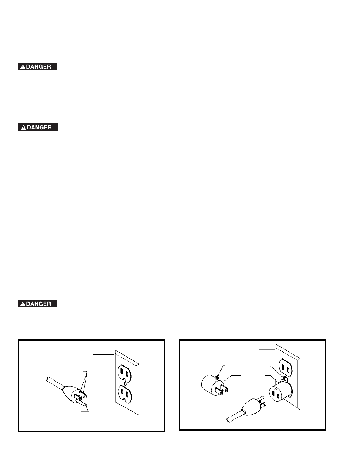
Use only 3-wire extension cords that have 3-prong grounding type plugs and matching 3-conductor receptacles that
accept the machine’ s plug, as shown in Fig. A.
Repair or replace damaged or worn cord immediately.
2. Grounded, cord-connected machines intended for use on a supply circuit having a nominal rating less than 150
volts:
If the machine is intended for use on a circuit that has an outlet that looks like the one illustrated in Fig. A, the machine
will have a grounding plug that looks like the plug illustrated in Fig. A. A temporary adapter, which looks like the adapter
illustrated in Fig. B, may be used to connect this plug to a matching 2-conductor receptacle as shown in Fig. B if a
properly grounded outlet is not available. The temporary adapter should be used only until a properly grounded outlet can
be installed by a qualified electrician. The green-colored rigid ear, lug, and the like, extending from the adapter must be
connected to a permanent ground such as a properly grounded outlet box. Whenever the adapter is used, it must be held
in place with a metal screw .
NOTE: In Canada, the use of a temporary adapter is not permitted by the Canadian Electric Code.
a qualified electrician check the receptacle.
In all cases, make certain that the receptacle in question is properly grounded. If you ar e not sur e, have
GROUNDED OUTLET BOX
CURRENT
CARRYING
PRONGS
GROUNDING BLADE
IS LONGEST OF THE 3 BLADES
Fig. A Fig. B
GROUNDED OUTLET BOX
GROUNDING MEANS
ADAPTER
6
Page 7
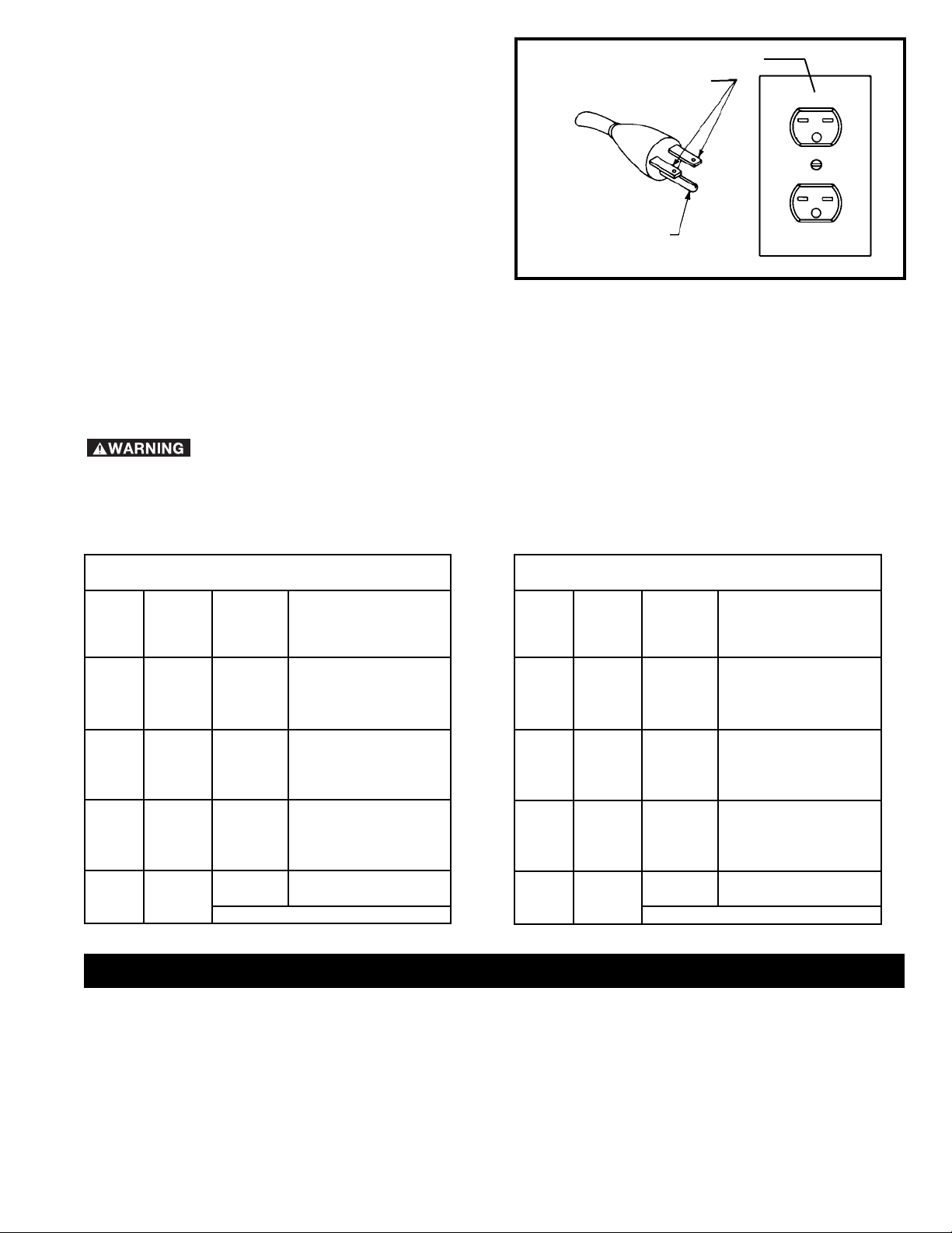
3. Grounded, cord-connected machines intended
for use on a supply circuit having a nominal rating
between 150 - 250 volts, inclusive:
If the machine is intended for use on a circuit that has an outlet
that looks like the one illustrated in Fig. C, the machine will
have a grounding plug that looks like the plug illustrated in Fig.
C. Make sure the machine is connected to an outlet having
the same configuration as the plug. No adapter is available
or should be used with this machine. If the machine must be
re-connected for use on a different type of electric circuit, the
re-connection should be made by qualified service personnel;
and after re-connection, the machine should comply with the
National Electric Code and all local codes and ordinances.
GROUNDED OUTLET BOX
CURRENT
CARRYING
PRONGS
GROUNDING BLADE
IS LONGEST OF THE 3 BLADES
4. Permanently connected machines:
Fig. C
If the machine is intended to be permanently connected, all wiring must be done by a qualified electrician and
conform to the National Electric Code and all local codes and ordinances.
* Three phase operation: Three phase machines are not supplied with a power cord and must be permanently
connected to a building’s electrical system. Extension cords can’t be used with a three phase machine.
EXTENSION CORDS
extension cord which has a 3-prong grounding type plug and matching receptacle which will accept the machine’s
plug. When using an extension cord, be sure to use one heavy enough to carry the current of the machine. An
undersized cord will cause a drop in line voltage, resulting in loss of power and overheating. Fig. D-1 or D-2, shows
the correct gauge to use depending on the cord length. If in doubt, use the next heavier gauge. The smaller the gauge
number, the heavier the cord.
MINIMUM GAUGE EXTENSION CORD
RECOMMENDED SIZES FOR USE WITH STATIONARY ELECTRIC MACHINES
Ampere
Rating Volts
0-6 120
0-6 120 25-50 16 AWG
0-6 120 50-100 16 AWG
0-6 120 100-150 14 AWG
6-10 120
6-10 120 25-50 16 AWG
6-10 120 50-100 14 AWG
6-10 120 100-150 12 AWG
10-12 120
10-12 120 25-50 16 AWG
10-12 120 50-100 14 AWG
10-12 120 100-150 12 AWG
12-16 120
12-16 120 25-50 12 AWG
12-16 120
Use proper extension cords. Make sure that your extension cord is in good condition and is a 3-wire
MINIMUM GAUGE EXTENSION CORD
RECOMMENDED SIZES FOR USE WITH STATIONARY ELECTRIC MACHINES
Total
Length of
Cord in
Feet
up to
25 18 AWG
up to
25 18 AWG
up to
25 16 AWG
up to
GREATER THAN 50 FEET NOT RECOMMENDED
Fig. D-1 Fig. D-2
Gauge of Extension
Cord
25 14 AWG
Ampere
Rating Volts
0-6 240
0-6 240 50-100 16 AWG
0-6 240 100-200 16 AWG
0-6 240 200-300 14 AWG
6-10 240
6-10 240 50-100 16 AWG
6-10 240 100-200 14 AWG
6-10 240 200-300 12 AWG
10-12 240
10-12 240 50-100 16 AWG
10-12 240 100-200 14 AWG
10-12 240 200-300 12 AWG
12-16 240
12-16 240 50-100 12 AWG
12-16 240
Total
Length of
Cord in
Feet
up to
50 18 AWG
up to
50 18 AWG
up to
50 16 AWG
up to 50
GREATER THAN 50 FEET NOT RECOMMENDED
Gauge of Extension
Cord
14 AWG
FUNCTIONAL DESCRIPTION
FOREWORD
Delta Models 28-248 and the 28-475X are 14" wood cutting band saws. The band saws have a quick-tensioning
blade mechanism for ease in changing blades and applying tension to the blade. These models have large 16"x16"
cast iron tables that can be tilted 45° to the right and 8° to the left. The band saws also come with a 4" O.D. dust port
for connecting the band saws to a dust collector.
NOTICE: The photo on the manual cover illustrates the current production model. All other illustrations contained in
the manual are representative only and may not depict the actual color, labeling, or accessories and are intended to
illustrate technique only.
7
Page 8
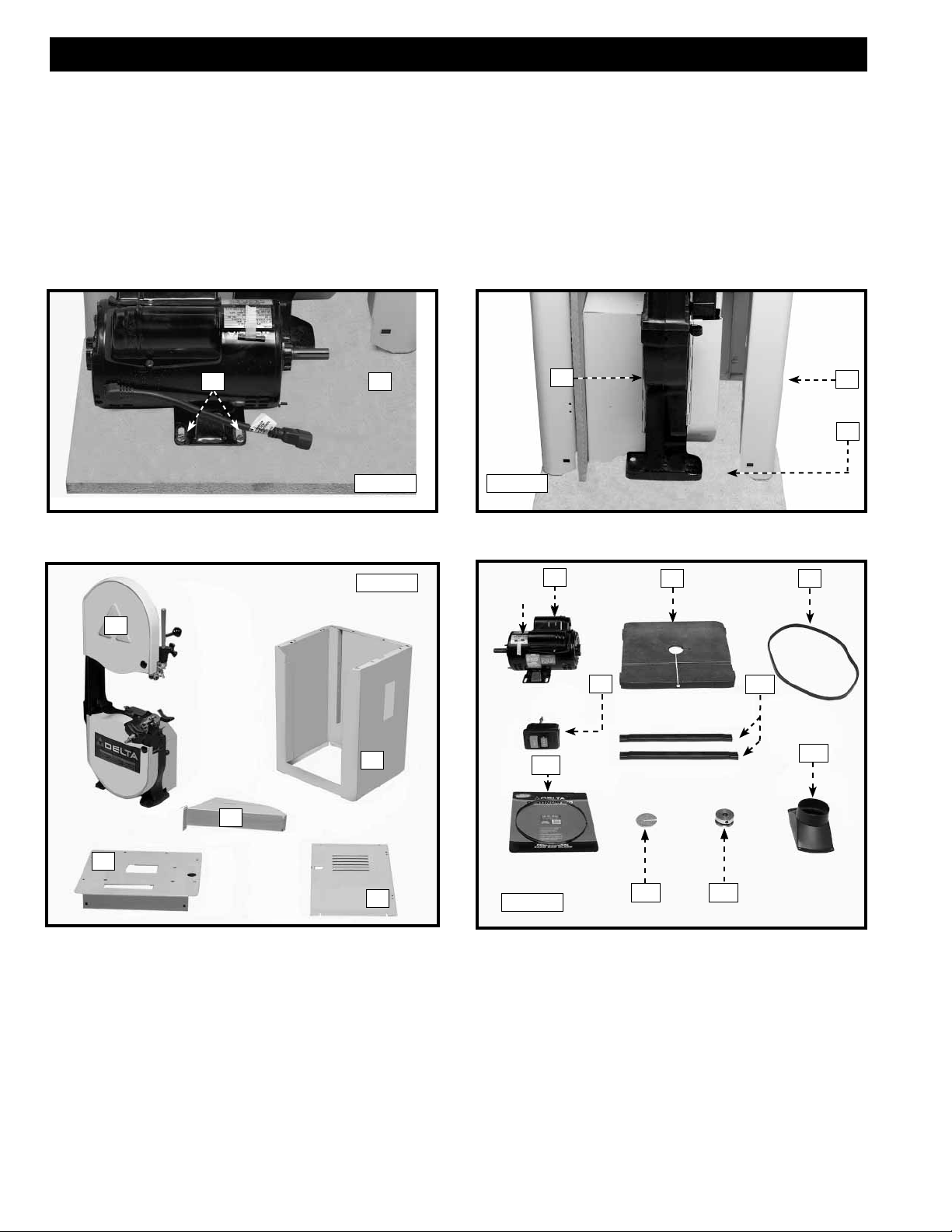
CARTON CONTENTS
UNPACKING AND CLEANING
Carefully unpack the machine and all loose items from the shipping container(s). Remove the protective coating from
all unpainted surfaces. This coating may be removed with a soft cloth moistened with kerosene (do not use acetone,
gasoline or lacquer thinner for this purpose). After cleaning, cover the unpainted surfaces with a good quality household
floor paste wax.
1. Remove the cardboard box from the packing skid (A) Fig. 1.
2. Use a 3/8" wrench to remove the two bolts (B) Fig. 1 that attach the motor to the packing skid.
3. Remove the bolts that attach the stand (C) Fig. 2 and the saw (D) to the the packing skid (A) with a 1/2" wrench.
B
A
D
C
A
Fig. A
Fig. C
1
1
Fig. B
K
E
Y
6
9
7 8
10
3
2
2
4
3
5
12
11
4
5
1. Saw
2. Stand
3. Dust Chute
4. Top Plate
5. Stand Door
NOTE: LVC box and hardware are included with certain
models.
Fig. D
13
14
6. Motor and key (A)
7. Table
8. Belt
9. On/Off Switch
10 Motor Bracket (2)
11. Dust Spout
12. Blade
13. Table Insert
14. Motor Pulley
8
Page 9
15
19
Fig. F
16
17
18
Fig. E
15. 5/16-18 x 1-1/2" Hex Head Screw (4)
16. 5/16-18 x 3/4" Carriage Head Bolt (16)
17. #10-24 x 1/2" Socket Head Cap Screw (8)
18. #10-32 x 1/2" Pan Head Screw (4)
19. 5/16" Flat Washer (4)
20. 7/16" Jam Nut (2)
21. 7/16" Locknut (2)
22. 5/16-18 Hex Nut (20)
23. #10-32 Hex Nut (4)
20
21
22
23
ASSEMBLY
ASSEMBLY TOOLS REQUIRED
3/8" Wrench
5/16" Wrench
7/16" Wrench
1/2" Wrench
25
26
24. Table Handle (2)
25. Male Hinge (2)
26. Door Latch
27. Female Hinge (2)
28. Cord Bushing
4mm Hex Wrench
Phillips Screwdriver
27
24
28
ASSEMBLY TIME ESTIMATE
Approximately 2-4 hours
ATTACHING THE MOTOR BRACKET TO THE STAND
1. Place the stand on its side (Fig. 3).
2. Align the two holes in the motor bracket (A) Fig. 4 with the two holes in the stand.
NOTE: Counting from the left of Fig. 3, attach the motor brackets to the holes (#1 and #3) in the front cabinet flange
(D), and holes (#2 and #5) in the rear cabinet flange (E).
NOTE: Position the slots of the motor bracket (C) Fig. 4 closer to the front cabinet flange (D) rather than the rear
cabinet flange (E).
3. Insert a 5/16-18 x 3/4" carriage head bolt through the hole in the motor bracket (A) Fig. 4, and the hole in the
stand.
4. Thread a 5/16-18 hex nut on the bolt and tighten securely.
5. Repeat this process for the other hole in the motor bracket.
6. Attach the other motor bracket to the stand in the same manner.
E
2
5
E
1
D
3
Fig. 3
9
D
C
A
Fig. 4
Page 10

ATTACHING THE MOTOR TO THE MOTOR BRACKET
1. Position the motor (A) Fig. 5 on the motor brackets (B). Align the holes in the motor with the holes in the motor
bracket.
2. Insert a 5/16-18 x 3/4" carriage head bolt through the hole in the motor bracket and the hole in the motor.
3. Thread a 5/16-18 hex nut on to the bolt.
NOTE: Hand-tighten the hardware for future adjustment.
4. Repeat this process for the three remaining holes in the motor and motor bracket.
5. Place the stand upright (Fig. 6).
Fig. 5 Fig. 6
A
B
B
ATTACHING THE TOP PLATE TO THE STAND
NOTE: If your machine comes with an LVC starter box, refer to the enclosed supplemental instruction sheet for
mounting that equipment. Then follow these instructions:
1. Place the top plate (A) Fig. 7 on the top of the stand
(B).
NOTE: Place the switch cord (F) Fig. 7 through the
slotted hole (G) in the top plate (A) and insert a plastic
bushing (H) in the slotted hole (G).
2. Align the eight holes in the stand and top (6 in the
top and 2 on the side).
4. Insert a 5/16-18 x 3/4" carriage head bolt through
the top plate and the stand. Thread a 5/16-18 hex
nut on to the bolt.
5. Repeat this process for the seven remaining holes.
A
B
Fig. 7
H
F
G
NOTE: Make sure the door opening is at least 13" wide
before you tighten the screws.
10
Page 11

MOUNTING AN LVC BOX TO THE CABINET
SINGLE PHASE (MODELS 28-248F & 28-348F) & THREE PHASE (MODELS 28-248G & 28-248G)
NOTE: The single phase LVC box comes with a connected power cord. The three-phase LVC box does NOT come
with a power cord.
NOTE: Attach both the single phase model and the three-phase model according to the following instructions.
1. Loosen, but do not remove the three screws (A)
Fig. 1 on the back of the LVC box.
2. Insert the power cord (single phase only) through
the hole (C) Fig. 2 from inside the cabinet.
3. Insert the three screws on the back of the LVC box
(A) Fig. 1 into the three holes (B) Fig. 2 on the inside
of the cabinet. Push down on the box to engage
the screws in the slots to secure the box.
A
Fig. 7A
B
C
Fig. 7B
4. Tighten the three screws (A) Fig. 3 from the outside
of the cabinet to hold the LVC box in place.
A
Fig. 7C
11
Page 12

INSTALLING THE DUST CHUTE
1. Insert the dust chute through the door opening into the slot (A) Fig. 8 in the top of the stand.
NOTE: Place the motor cord behind the dust chute unless you are using the accessory height attachment with your
saw. In that case, position the cord in front of the dust chute.
NOTE: Be certain that the tab on the dust chute (B) Fig. 9 snaps into the cutout (C) in the top of the stand.
2. Align the two slotted holes (D) Fig. 10 in the bottom of the dust chute with the two holes (E) Fig. 11 in the stand.
A
B
C
Fig. 8
D
Fig. 10 Fig. 11
THE BAND SAW USED WITH A DUST COLLECTOR
To use this machine with a dust collector:
1. Align the four holes in the dust port (A) Fig. 12 with
the four holes in the side of the stand.
2. Insert a #10-32x1/2" pan head screw through the
two holes in the dust port (B) Fig. 12 and the stand.
Thread a #10-32 hex nut on the screw and tighten
securely.
3. Repeat this process for the two remaining holes (C)
in the dust port, stand, and dust chute.
Fig. 9
E
B
A
C
THE BAND SAW USED WITHOUT A DUST COLLECTOR
To use this machine without a dust collector:
1. Insert a #10-32 x 1/2" pan head screw through hole
(A) Fig. 13 in the stand and dust chute. Thread a #1032 hex nut onto the screw, and tighten securely.
2. Repeat this process for the remaining holes in the
stand.
12
Fig. 12
A
Fig. 13
Page 13

ATTACHING THE DOOR TO THE STAND
1. Align the two holes in one of the male hinges (A) Fig. 14 with the two holes on the stand.
NOTE: Point the hinge “up” (Fig. 14).
2. From the inside of the stand, insert a #10-24 x 1/2" socket head cap screw through the hole in the stand, and
thread the screw into the hinge. Repeat this process in the other hole to secure the hinge.
NOTE: Hand-tighten the hardware for further adjustment.
3. Attach the other hinge.
4. Use a straight edge to align the two hinges (Fig. 15).
5. Tighten the four hinge screws securely.
A
Fig. 14 Fig. 15
6. Align the two holes in one of the female hinges (C) Fig. 16 with the two holes in the stand door (D).
NOTE: Point the hinge opening “down”.
7. Thread a #10-24 x 1/2" socket head cap screw through the hole in the door and into the hole in the hinge. Secure
the hinge with the other screw.
NOTE: Hand-tighten the hardware for further adjustment.
8. Secure the other hinge.
9. Use a straight edge to align the two hinges (Fig. 17).
10. Tighten the four hinge screws securely.
11. Slide the two female hinges (C) Fig. 18 on the door over the two male hinges (A) on the stand.
12. The door latch is in one piece and snaps into the door. Insert the latch (A) Fig. 19 from the outside, through the
hole in the door.
13. Put pressure on the door latch to snap the latch in place.
14. To open the door, slide the latch away from the cabinet and pull the door.
D
C
Fig. 16
Fig. 17
A
C
A
Fig. 18
13
Fig. 19
Page 14

ATTACHING THE SAW TO THE STAND
The band saw is VERY heavy. Use a
helper to attach the saw to the stand.
1. Position the band saw on top of the stand (Fig. 20).
NOTE: Position the pulley (A) Fig. 20 over the belt
opening (B).
2. Align the four holes in the saw with the four holes in
the top of the stand.
3. Place a 5/16" flat washer on a 5/16-18 x 1-1/2" hex
head screw. Insert the screw through one of the
holes (C) in the saw and the stand.
4. Thread a 5/16-18 hex nut on the screw inside the
stand.
5. Repeat this process for the three remaining holes.
6. Tighten the screws securely.
ATTACHING THE MOTOR PULLEY
1. The pulley key (A) Fig. 21 is taped to the motor (see
#6 in “CARTON CONTENTS”). Remove it.
2. Position the pulley key (A) Fig. 21 in the slot (B) on
the motor shaft.
3. Align the slot in the motor pulley (C) Fig. 21 with the
key (A) on the motor shaft.
4. Slide the motor pulley (C) Fig. 21 on the motor
shaft.
5. Tighten the set screw (D) Fig. 21.
A
C
A
B
D
B
Fig. 20
C
Fig. 21
ATTACHING THE BELT TO THE SAW PULLEY AND THE MOTOR PULLEY
1. Install the belt over the saw pulley (A) Fig. 22.
2. Raise the motor and install the belt over the motor pulley (B) Fig. 23.
3. Place a straight edge (C) Fig. 23 through the belt opening in the saw stand and against the upper and lower back
of the saw pulley. Check the in/out alignment of the motor pulley against the straight edge. If necessary, adjust
the position of the motor pulley by loosening the set screw (D) Fig. 21 and moving the motor pulley in or out. After
alignment, tighten the set screw.
4. Push down on the motor and push in on the center of the belt. The correct deflection is approximately 1/4".
5. When the deflection is correct, tighten the four bolts that hold the motor to the motor bracket.
A
Fig. 22
C
B
Fig. 23
14
Page 15

ATTACHING THE TABLE TO THE SAW
1. Insert the two table studs (A) Fig. 24 on the bottom
of the table into the two holes in the trunnion
assemblies (B).
NOTE: Face the slot (C) Fig. 24 in the front of the table
toward the front of the saw.
2. Thread a 7/16" jam nut (C) Fig. 25 on each table
stud and tighten securely.
C
A
B
Fig. 24
C
Fig. 25
3. Place a table handle (H) on each stud (Fig. 26).
NOTE: Position the table handles as illustrated in Fig.
26.
4. Thread a 7/16" locknut (D) Fig. 27 on each stud.
Tighten each locknut up to the table handle, then
loosen them 1/2 of a turn.
H
Fig. 26
A
Fig. 27
15
Page 16

ATTACHING THE BLADE TO THE SAW
Use only 93-1/2" blades on the 14" band saw.
1. Remove the table pin (A) Fig. 28.
2. Open the blade guard door (C) Fig. 28, then open the two wheel-guard doors (B) Fig. 28.
3. Move the quick tension lever (D) Fig. 28 toward the back of the saw to relieve tension.
NOTE: Install the blade with the teeth pointing down.
4, Slide the blade through the slot (E) Fig. 28 in the band saw table.
5. Place the blade around the two wheel assemblies (A) Fig. 29.
6. Replace the table pin (A) Fig. 28.
7. Close the two wheel-guard doors (B) Fig. 28 and the blade-guard door (C).
8. Move the quick tension lever (D) Fig. 29 toward the front of the saw to tension the blade.
9. See the section “OPERATING CONTROLS AND ADJUSTMENTS” to adjust the blade tension and tracking.
B
E
A
B
C
Fig. 28
D
INSTALLING THE TABLE INSERT
Install the table insert (A) Fig. 30 in opening of table.
NOTE: A tab (B) is provided on the insert to engage the
notch (C) in table opening.
D
A
Fig. 29
C
16
A
B
Fig. 30
Page 17

ATTACHING THE ON / OFF SWITCH TO THE STAND
1. Remove the two outer hex nuts and lock washers (A) Fig. 31 from the two screws on the back of the switch box (B).
2. Insert the two screws (C) Fig. 32 (located on the back of the switch box) into the two holes (D) in the band saw arm.
3. Use the two nuts and lockwashers (L) Fig. 33, removed in STEP 1, to fasten the switch box to the bandsaw arm.
4. Remove the screw and cable clamp (E) Fig. 34 from the lower arm of the band saw.
5. Insert the switch cord and power cord (F) Fig. 34 in the clamp (E) (removed in STEP 4), and fasten the clamp to the
bandsaw.
6. Insert the cord bushing into the hole (G) Fig. 35 on the top of the band saw stand.
7. Insert the switch cord (H) Fig. 36 through the cord bushing (G).
8. Insert the motor plug (J) Fig. 37 into the receptacle (H) of switch cord.
Position the motor plug (J) Fig. 37 and the switch cord (H) behind the dust chute (K).
NOTE: If you use the accessory height attachment with your saw, position the cords in front of the dust chute.
D
B
A
C
Fig. 31
Fig. 32
F
L
E
Fig. 33
Fig. 34
H
G
Fig. 35
G
Fig. 36
J
K
H
Fig. 37
17
Page 18

OPERATION
OPERATIONAL CONTROLS AND ADJUSTMENTS
STARTING AND STOPPING THE SAW
1. The on/off switch is located on the left side of the
machine. To tur n the machine “ON”, push the green
start button (A) Fig. 38.
2. To turn the machine “OFF”, push the red stop
button.
Make sure that the switch is in the "OFF"
position before plugging in the power cord. In the event
of a power failure, move the switch to the "OFF" position.
An accidental start-up can cause injury .
LOCKING SWITCH IN THE “OFF” POSITION
IMPORTANT: When the tool is not in use, the switch
should be locked in the “OFF” position to prevent
unauthorized use, using a padlock (C) Fig. 39 with a
3/16" diameter shackle.
A
B
C
Fig. 38
TILTING THE TABLE
Disconnect the machine from the power source!
1. You can tilt the band saw table 45° to the right and
9° to the left. To tilt the table to the right, loosen the
two clamp handles (A) Fig. 40, tilt the table to the
desired angle. Tighten the locking handles (A) Fig.
40.
2. To tilt the table to the left, loosen the two locking
handles (A) Fig. 40 and tilt the table to the right.
Rotate the table stop (B) Fig. 41 all the way to
the right. Tilt the table to the left. Tighten the two
locking handles (A) Fig. 40.
NOTE: Use the scale (C) Fig. 41 to select the angle of
tilt, both right and left.
Fig. 39
A
C
Fig. 40
18
C
Fig. 41
Page 19

ADJUSTING THE 90° DEGREE TABLE STOP
DISCONNECT MACHINE FROM POWER SOURCE!
1. Loosen the table clamp handles (A) Fig. 40, and tilt the table to the right.
2. Rotate the stop (B) Fig. 42 out of the way.
3. Place a square (G) Fig. 43 on the table and against the blade and position the table 90° to the blade.
4. Clamp table handles (A) Fig. 40.
5. Rotate the stop (B) Fig. 42 until the tallest screw contacts or is under the table skirt.
6. If the screw is too high, lower it until the top of the screw touches the bottom of the table skirt (B) Fig. 42. If the
screw is low, raise it until it touches the bottom of the table skirt.
7. Set the pointer (J) Fig. 44 to “0” degree mark by loosening the screw (K) Fig. 44. Move the pointer (J) and tighten
screw (K).
B
F
G
Fig. 42
Fig. 43
SETTING THE ADJUSTABLE STOPS
The machine comes with two adjustable stops. You can adjust these stops to provide a positive stop at two predetermined angles of your choice.
Disconnect the machine from the power source!
1. Loosen the two clamp handles (A) Fig. 40.
2. Tilt the table to the right and turn the stop until either stop screw (M) or (N) Fig. 45 is under the table skirt.
3. Tilt the table to the left until it rests on the selected stop screw (M) or (N) Fig. 45.
4. Set the the table to the desired angle by turning the stop screw and checking the angle on the side of the scale
with pointer (J) Fig. 44.
5. Adjust the other stop screw in the same manner.
M
J
K
Fig. 44
N
Fig. 45
19
Page 20
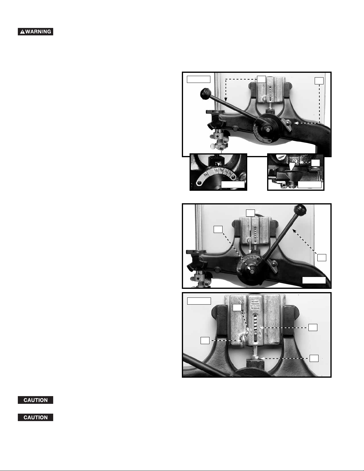
ADJUSTING THE BLADE TENSION
Disconnect the machine from the power source!
To apply tension to the blade, move the tension handle (A) Fig. 46 to the left. To release the blade tension, move the
tension handle slightly to the left, lift the lever lock (B) Fig. 46 and move the tension handle (A) to the right (Fig. 47).
To adjust the blade tension:
1. Move the tension handle (A) slightly to the left,
lift the lever lock (B) Fig. 46, and move the blade
tension handle to the right.
2. You can set the blade tension lever to match blade
widths 3/4", 1/2", 3/8", 1/4", and 1/8" (See Inset 1
- Fig.46).
3. Move the blade tension lever to the right as far as
it will go. Pull outward (away from the saw) on the
entire handle assembly (A) Fig. 47, and turn the the
assembly until the appropriate width of the blade
is shown on the top of the blade tension scale (C).
Release the handle assembly so that the handle is
contacting the hub (D).
Fig. 46
A
Inset 1 Inset 2
C
D
B
A
A
NOTE: To adjust the pointer on the blade tension scale,
loosen the screw (A) Inset 2 - Fig. 46, move the pointer,
and tighten the screw.
4. Move the blade tension lever to the left until the
lever lock (B) Fig. 46 engages the blade tension
lever handle (A).
5. To fine-tune the band saw blade tension, turn the
adjustment nut (N) Fig. 48.
6. A series of graduations (T) Fig. 48 is located on
the back of the upper wheel-slide bracket. These
graduations indicate the proper tension for various
widths of blades.
NOTE: These graduations are correct for average work,
and will not be affected by rebrazing of the saw blade.
When cutting thin pieces (3/4" or less), set the blade tension below the maximum setting for blade width
to extend the life of the blade.
Over-straining is a common cause of blade br eakage and/or other unsatisfactory blade performance. Release
the tension when the tool is not in use.
Fig. 47
Fig. 48
B
T
C
N
20
Page 21

TRACKING THE BLADE
Disconnect the machine from the power source!
Before tracking the blade, make sure that the blade guides and blade support bearings are clear of the
blade.
After applying tension to the blade, rotate the wheels
slowly forward by hand and observe the blade’s
movement. The blade (A) Fig. 49 should travel in the
center of the upper tire. If the blade creeps toward the
front edge, loosen the wing nut (B) Fig. 48, and turn the
thumb screw (C) clockwise. This procedure draws the
blade toward the center of the tire. If the blade creeps
toward the back edge, turn the thumb screw in the
opposite direction. Adjust the thumb screw (C) Fig. 48
only a fraction of a turn each time.
Never track the blade while the machine is running.
A
Fig. 49
After the blade is tracking in the center of the tires, tighten the wing nut (B) Fig. 48.
VERTICAL ADJUSTMENT OF THE UPPER BLADE GUIDE ASSEMBLY
Disconnect the machine from the power source!
To adjust the blade guides and bearings:
1. Set the upper blade guide assembly (A) Fig. 50
as close as possible to the top surface of the
workpiece.
2. Loosen the lock knob (B) and move the guide
assembly (A) to the desired position.
3. Tighten the lock knob.
A
B
Fig. 50
21
Page 22

ADJUSTING THE UPPER BLADE GUIDES AND BLADE SUPPORT BEARING
Adjust the upper blade guides and blade support bearings ONLY AFTER the blade has the correct tension and is
tracking properly. To adjust:
Disconnect the machine from the power source!
1. Make sure that the bottom blade guides and support bearings are not touching the blade.
2. Check the upper blade guide assembly. The blade guides (A) Fig. 51 should be parallel to the blade. To adjust,
loosen the screw (B) and rotate the complete guide assembly (C). When the blade guides are parallel with the
blade, tighten the screw (B).
3. Adjust the guides (A) Fig. 52 so that the front edge of the guides is just behind the “gullets” of the saw teeth. The
complete guide block bracket can be moved in or out by loosening the thumb screw (C) and turning the knurled
knob (D) Fig. 52. When the guides (A) are set properly, tighten the thumb screw.
4. Loosen the set screws (B) to move the guides (A). Place them as close as possible to the side of the blade. (Be
careful not to pinch the blade). Tighten the screws (B).
5. When the blade guide wears to a point that it cannot be adjusted close to the blade, loosen the screw (B) Fig. 55
and reverse the blade guides (A) Fig. 52.
6. The upper blade support bearing (E) Fig. 52 prevents damage to the set in the saw teeth by keeping the blade
from being pushed too far toward the back. The support bearing (E) should be set 1/64" behind the blade. Loosen
the thumb screw (F) and turn the knurled knob (G) to move the support bearing (E) in or out.
7. Adjust the blade support bearing (E) so that the back edge of the blade overlaps the outside diameter of the ball
bearing by about 1/16". The bearing (E) is set on an eccentric. To change the position, remove the screw (H) and
bearing (E) Fig. 52. Loosen the thumb screw (F) and back out the knurled knob from the set screw. Remove the
hex shaft from the hole, and rotate it to move the eccentric for the bearing.
Fig.51
C
A
B
Fig. 52
E
D
A
G
B
F
H
A
ADJUSTING LOWER BLADE GUIDES AND BLADE SUPPORT BEARING
Adjust the lower blade guides and blade support bearing after the upper guides and bearing have been adjusted.
Disconnect the machine from the power source!
1. Turn the knurled knob (C) Fig. 53 to adjust the front
edge of the guide blocks (B) so that they are just
behind the “gullets” of the saw teeth. Check the
support bearing (D). It should not be touching the
back of the blade.
2. Loosen the two screws (A) Fig. 53. Move the guides
(B) as close as possible to the side of the blade,
being careful not to pinch the blade. Tighten screws
(A).
3. Turn the other knurled knob (E) to adjust the lower
blade support bearing (D) Fig. 53 so that it is about
1/64" behind the back of the blade.
Fig. 53
A
E
B
C
D
C
22
Page 23

MACHINE USE
Before starting the machine, ensure that all adjustments are properly made and the guards are in place. Turn the
upper wheel by hand to make sure that everything is correct BEFORE turning on the power.
Keep the top blade guide (and guard) within 1/8" of the work piece at all times. Do not force the
material against the blade. Light pressure on the work piece will produce a smoother cut, and prevent excess
friction and heating of the blade.
KEEP THE SAW BLADE SHARP. Very little forward pressure is required for normal cutting. Keep the workpiece
moving at a slow and consistent rate against the blade to ensure a smooth and accurate cut.
Avoid twisting the blade, by trying not to turn sharp corners. Remember, you must saw around corners.
CUTTING CURVES
When cutting curves, turn the stock
carefully so that the blade follows without
twisting. If a curve is so abrupt that it is
necessary to repeatedly back up and cut
a new kerf, then a narrower blade, a blade
with more set, or additional relief cuts Fig.
54 may be necessary to allow the blade to
cut more efficiently. The more set a blade
has, the easier it will allow the stock to be
turned, but the cut is usually rougher.
When withdrawing the piece being cut,
changing the cut, or for any other reason,
be careful not to accidentally draw the
blade off the wheels. In most cases, it is easier and safer to turn the stock and saw out through the waste material,
rather than try to withdraw the stock from the blade.
Fig. 54
TROUBLESHOOTING GUIDE
In spite of how well a band saw is maintained, problems can occur. The following troubleshooting guide will help you
solve the more common problems. For assistance with your machine, visit our website at www.deltamachinery.com
for a list of service centers or call the DELTA Machinery help line at 1-800-223-7278 (In Canada call 1-800-463-3582).
Trouble: SAW WILL NOT START.
Probable Cause Remedy
1. Switch cord / motor cord not plugged in. 1. Plug in switch cord / motor cord.
2. Fuse blown or motor reset tripped. 2. Replace fuse or push motor reset button.
3. Cord damaged. 3. Have cord replaced.
Trouble: BREAKER OR MOTOR KICKS OUT FREQUENTLY.
Probable Cause Remedy
1. Extension cord too light or too long. 1. Replace with adequate size cord.
2. Feeding stock too fast. 2. Feed stock more slowly.
3. Blade in poor condition (dull, warped, gummed). 3. Clean or replace blade.
4. Low voltage supply. 4. Contact an electrician.
Trouble: BAND SAW VIBRATES EXCESSIVELY.
Probable Cause Remedy
1. Machine not mounted securely to stand. 1. Tighten all mounting hardware.
2. Stand on uneven surface. 2. Reposition on flat level surface.
3. Worn belt. 3. Replace belt.
4. Pulley not aligned. 4. Adjust motor pulley.
5. Motor not fastened securely. 5. Tighten all mounting hardware.
23
(continued on next page)
Page 24

Trouble: BAND SAW DOES NOT COME UP TO SPEED.
Probable Cause Remedy
1. Low voltage due to improper extension cord size. 1. Replace with adequate size cord.
2. Low voltage. 2. Contact an electrician.
3. Motor wired for incorrect voltage. 3. Rewire motor for correct voltage.
Trouble: BLADES BREAK.
Probable Cause Remedy
1. Blade not tensioned properly. 1. Adjust blade tension.
2. Blade guides improperly adjusted. 2. Check and adjust blade guides.
3. Blade support bearing improperly adjusted. 3. Adjust blade support bearing.
4. Blade wheel tracking adjustment improperly set. 4. Check and adjust blade tracking.
5. Bad weld on blade. 5. Replace the blade.
6. Worn tires. 6. Replace tires.
7. Forcing wide blade around short radius. 7. Change to a narrower blade.
8. Dull blade or insufficient set. 8. Replace blade.
9. Upper blade guide set too high. 9. Set upper blade guide within 1/8" of workpiece.
10. Continuous running of machine when not actually 10. Turn off machine when not performing cutting
cutting. operation.
Trouble: BLADE WILL NOT TRACK.
Probable Cause Remedy
1. Blade too loose 1. Adjust tension
2. Upper wheel not properly adjusted. 2. Adjust upper wheel.
3. Improperly adjusted blade support bearing. 3. Adjust blade support bearing.
Trouble: CUT DOES NOT AGREE WITH SETTING ON THE TILT SCALE.
Probable Cause Remedy
1. Pointer out of adjustment 1. Adjust pointer.
Trouble: BLADE WILL NOT STAY ON WHEEL.
Probable Cause Remedy
1. Blade not tensioned properly. 1. Adjust blade tension.
2. Blade guides improperly adjusted. 2. Check and adjust blade guides.
3. Blade support bearing improperly adjusted. 3. Adjust blade support bearing.
4. Blade wheel not tracking properly. 4. Check and adjust blade tracking.
5. Bad weld on blade. 5. Replace the blade.
6. Worn tires. 6. Replace tires.
Trouble: BAND SAW MAKES UNSATISFACTORY CUTS.
Probable Cause Remedy
1. Blade not tensioned properly. 1. Adjust blade tension.
2. Blade guides improperly adjusted. 2. Check and adjust blade guides.
3. Blade support bearing improperly set. 3. Adjust blade support bearing.
4. Blade wheel not tracking properly. 4. Check and adjust blade tracking.
5. Bad weld on blade. 5. Replace the blade.
6. Worn tires. 6. Replace tires.
7. Incorrect blade for work being done. 7. Change the blade.
8. Dull blade or insufficient set. 8. Replace blade.
9. Upper blade guide set too high. 9. Set upper blade guide within 1/8" of work piece.
24
Page 25

BAND SAW BLADES
A band saw blade is a delicate piece of steel that is subjected to tremendous strain. You can obtain long use from a
band saw blade if you use it properly. Be sure to use blades of the proper thickness, width, and temper for the various
types of material and cuts.
Always use the widest blade possible. Use narrow blades only for sawing small, abrupt curves and for fine, delicate
work. This will save blades and will produce better cuts. For cutting wood and similar materials, Delta offers blades in
widths of 1/8", 1/4", 3/8", 1/2", and 3/4".
Any one of a number of conditions may cause a band saw blade to break. Blade breakage is, in some cases,
unavoidable, because of the peculiar stresses to which blades are subjected. Blades will break often due to avoidable
causes, such as the lack of care to the blade or the blade not being properly adjusted to the band saw. The most
common causes of blade breakage are:
(1) faulty alignments and adjustments of the guides.
(2) forcing or twisting a wide blade around a curve of short radius.
(3) feeding the work piece too fast into the blade.
(4) dullness of the teeth, or absence of sufficient set.
(5) improperly tensioned blade.
(6) top guide set too high above the work piece being cut.
(7) using a blade with a lumpy or improperly finished braze or weld.
(8) continuous running of the saw blade when not cutting.
Use blades that are 93-1/2" long on this machine.
Always use a sharp blade. Keep it free from gum and pitch. Clean frequently with a stiff fiber brush.
Narrow blades are used for cutting small circles or curves while the wider blades are best suited for straight cutting
such as ripping.
A new blade, in most cases, will perform better and last longer than a re-sharpened blade.
Ensure that the blade guides are adjusted properly.
Do not force or twist the blade around a curve or a very short radius.
Feed the workpiece through the blade at a consistent rate, allow the blade to do the cutting – do not feed the work
piece too fast.
Do not apply excessive tension to the blade. The tension is only necessary to drive the blade without slipping on the
wheels. Narrow blades require less tension than wider blades.
MAINTENANCE
KEEP MACHINE CLEAN
Periodically blow out all air passages with dry compressed
air. All plastic parts should be cleaned with a soft damp
cloth. NEVER use solvents to clean plastic parts. They
could possibly dissolve or otherwise damage the material.
WEAR ANSI Z87.1 SAFETY GLASSES
WHILE USING COMPRESSED AIR.
FAILURE TO START
Should your machine fail to start, check to make sure
the prongs on the cord plug are making good contact
in the outlet. Also, check for blown fuses or open circuit
breakers in the line.
LUBRICATION
Apply household floor paste wax to the machine table
and extension table or other work surface weekly .
PROTECTING CAST IRON FROM RUST
To clean and protect cast iron tables from rust, you will
need the following materials: 1 pushblock from a jointer,
1 sheet of medium Scotch-Brite™ Blending Hand Pad,
1 can of WD-40®, 1 can of degreaser, 1 can of TopCote
Aerosol. Apply the WD-40® and polish the table surface
with the Scotch-Brite pad using the pushblock as a
holddown. Degrease the table, then apply the TopCote
accordingly.
25
®
®
Page 26

SERVICE
REPLACEMENT PARTS
When servicing use only identical replacement parts. Check
the parts list included for more information. Parts lists can
also be found online at www.deltamachinery.com.
SERVICE AND REPAIRS
All quality tools will eventually require servicing, or
replacement of parts due to wear from normal use. For
assistance with your tool, visit our website at www.
deltamachinery.com for a list of service centers or call
the Customer Care Department at 1-800-223-7278. All
repairs made by our service centers are fully guaranteed
against defective material and workmanship. We cannot
guarantee repairs made or attempted by others. Should
you have any questions about your tool, feel free to write
us at any time. In any communications, please give all
information shown on the nameplate of your tool (model
number, type, serial number, etc.).
ACCESSORIES
A complete line of accessories is available from your Delta Supplier, Porter-Cable • Delta Factory Service Centers, and
Delta Authorized Service Stations. Please visit our Web Site www.deltamachinery.com for a catalog or for the name of
your nearest supplier.
Since accessories other than those offered by Delta have not been tested with this product, use
of such accessories could be hazardous. For safest operation, only Delta recommended accessories should be
used with this product.
26
Page 27

WARRANTY
To register your tool for warranty service visit our website at www.deltamachinery.com.
Two Year Limited New Product Warranty
Delta will repair or replace, at its expense and at its option, any new Delta machine, machine part, or machine accessory
which in normal use has proven to be defective in workmanship or material, provided that the customer returns the
product prepaid to a Delta factory service center or authorized service station with proof of purchase of the pr oduct within
two years and provides Delta with reasonable opportunity to verify the alleged defect by inspection. For all refurbished
Delta product, the warranty period is 180 days. Delta may require that electric motors be returned prepaid to a motor
manufacturer’s authorized station for inspection and repair or replacement. Delta will not be responsible for any asserted
defect which has resulted from normal wear, misuse, abuse or repair or alteration made or specifically authorized by
anyone other than an authorized Delta service facility or representative. Under no circumstances will Delta be liable
for incidental or consequential damages resulting from defective products. This warranty is Delta’s sole warranty and
sets forth the customer’s exclusive remedy, with respect to defective products; all other warranties, express or implied,
whether of merchantability, fitness for purpose, or otherwise, are expressly disclaimed by Delta.
Page 28

Delta Machinery
4825 Highway 45 North
Jackson, TN 38305
www.deltamachinery.com
28
 Loading...