

Page 1

INSTRUCTION MANUAL
D AT E D 6-10-99 PA RT NO. 426-02-651-0032
'Delta International Machinery Corp. 1999
Platinum Edition
14 Band Saw
(Model 28-255)
Page 2

2
TABLE OF CONTENTS
SAFETY RULES...............................................................................................................................................................3
ADDITIONAL SAFETY RULES FOR BAND SAW S........................................................................................................4
UNPACKING AND CLEANING ........................................................................................................................................4
ASSEMBLING THE MOBILE BASE................................................................................................................................5
Raising And Lowering The Mobile Base ..............................................................................................................6
ASSEMBLING THE BAND SAW .....................................................................................................................................6
Assembling Motor To Stand ..................................................................................................................................7
Assembling Motor Pulley .......................................................................................................................................8
Assembling Band Saw To Stand ...........................................................................................................................8
Assembling And Aligning V-Belt; Adjusting Belt Tension..................................................................................8
Assembling Belt And Pulley Guard ......................................................................................................................9
Assembling Switch .................................................................................................................................................9
Assembling Rip Fence .........................................................................................................................................10
CONNECTING BAND SAW TO POWERSOURCE
Power Connections ..............................................................................................................................................12
Motor Specifications ............................................................................................................................................12
Grounding Instructions ........................................................................................................................................13
Extension Cords ...................................................................................................................................................13
OPERATING CONTROLS AND ADJUSTMENTS
Starting And Stopping The Saw ..........................................................................................................................14
Locking The Switch In The OFF Position .......................................................................................................14
Table Insert ............................................................................................................................................................14
T ilting The Table ...................................................................................................................................................15
Adjusting Table S top ............................................................................................................................................15
Adjusting Blade Tension ......................................................................................................................................16
Tracking The Blade ...............................................................................................................................................16
Adjusting Upper Blade Guide Assembly............................................................................................................17
Adjusting Upper Blade Guides And Blade Support Bearing ...........................................................................17
Adjusting Lower Blade Guides And Blade Support Bearing ...........................................................................18
CHANGING THE BLADE ...............................................................................................................................................18
BAND SAW BLADES.....................................................................................................................................................18
OPERATING T H E BANDSAW .......................................................................................................................................19
Cutting Curves ......................................................................................................................................................19
Resawing ...............................................................................................................................................................19
PAR T S , SERVICE A N D W ARRANTY ASSISTANCE....................................................................................................20
W ARRANTY....................................................................................................................................................................20
Page 3

3
SAFETY RULES
W oodworking can be dangerous if safe and proper operating procedures are not followed. As with all machinery, there are cert ain
hazards involved with the operation of the product. Using the machine with respect and caution will considerably lessen the possi bility of personal injury . However, if normal safety precautions are overlooked or ignored, personal injury to the operator may result.
Safety equipment such as guards, push sticks, hold-downs, featherboards, goggles, dust masks and hearing protection can reduce
your potential for injury . But even the best guard won t make up for poor judgment, carelessness or inattention. Always use common
sense and exercise caution in the workshop. If a procedure feels dangerous, don t try it. Figure out an alternative procedure that feels
safer . REMEMBER: Your personal safety is your responsibility .
This machine was designed for cert ain applications only . Delt a Machinery strongly recommends that this machine not be modified
and/or used for any application other than that for which it was designed. If you have any questions relative to a p articular applica tion, DO N O T use the machine until you have first contacted Delt a to determine if it can or should be performed on the product.
DE LTA INTERNATIONAL MACHINERY CORP.
MANAGER OF TECHNICAL SERVICES
246 ALPHA DRIVE
PITTSBURGH, PENNSYLVANIA 15238
(IN CANADA: 644 IMPERIAL ROAD, GUELPH, ONTARIO N1H 6M7)
W ARNING: FAILURE TO FOLLOW THESE RULES
M AY RESULT IN SERIOUS PERSONAL INJURY
1. FOR YOUR O W N SAFETY, READ INSTRUCTION
MANUAL BEFORE OPERATING T H E TO O L. Learn the
tool s application and limit ations as well as the specific
hazards peculiar to it.
2. KEEP GUARDS IN PLACE and in working order .
3. ALWAYSWEAREYEPROTECTION.
4. REMOVEADJUSTING KEYS AND WRENCHES. Form
habit of checking to see that keys and adjusting wrenches are
removed from tool before turning it on.
5. KEEP WORKAREA CLEAN. Cluttered areas and
benches invite accident s.
6. DON T USE IN DANGEROUS ENVIRONMENT. Don t
use power tools in damp or wet locations, or expose them
to rain. Keep work area well-lighted.
7. KEEP CHILDREN A N D VISITO R S A W A Y . All children
and visitors should be kept a safe dist ance from work area.
8. MAKE WORKSHOP CHILDPROOF with p adlocks,
master switches, or by removing st arter keys.
9. DON T FORCE TO O L. It will do the job better and be
safer at the rate for which it was designed.
10. US E RIGHT TO O L. Don t force tool or att achment to do
a job for which it was not designed.
11. WEAR PROPER APPAREL. No loose clothing, gloves,
neckties, rings, bracelet s, or other jewelry to get caught in
moving part s. Nonslip footwear is recommended. Wear
protective hair covering to cont ain long hair .
12. A LW AYS U SE SAFETY GLASSES.W ear safety glasses.
Everyday eyeglasses only have impact resist ant lenses;
they are not safety glasses. Also use face or dust mask if
cutting operation is dusty.
13. SECURE WORK. Use clamp s or a vise to hold work
when practical. It s safer than using your hand and frees
both hands to operate tool.
14. DON T OVERREACH. Keep proper footing and balance
at all times.
15. MAINTAIN TOOLSIN TO P CONDITION. Keep tools
sharp and clean for best and safest performance. Follow
instructions for lubricating and changing accessories.
16. DISCONNECT TOOLS before servicing and when
changing accessories such as blades, bit s, cutters, etc.
17. USERECOMMENDED ACCESSORIES. The use of
accessories and att achments not recommended by Delt a
may cause hazards or risk of injury to persons.
18. REDUCE THE RISK O F UNINTENTIONAL STAR TI N G . Make sure switch is in OFF position before plugging
in power cord.
19. NEVER STAND O N TOOL. Serious injury could occur
if the tool is tipped or if the cutting tool is accident ally
cont acted.
20. CHECK DAMAGEDPARTS. Before further use of the
tool, a guard or other p art that is damaged should be care fully checked to ensure that it will operate properly and
perform it s intended function check for alignment of moving
part s, binding of moving p art s, breakage of p art s, mounting,
and any other conditions that may af fect it s operation. A
guard or other p art that is damaged should be properly
rep aired or replaced.
21. DIRECTION O F FEED. Feed work into a blade or cutter
against the direction of rot ation of the blade or cutter only .
22.
NEVER LEAVE TOOL RUNNING UNATTENDED. TURN
POWEROFF
. Don t leave tool until it comes to a complete
stop.
23. DRUGS, ALCOHOL, MEDICATION. Do not operate
tool while under the influence of drugs, alcohol or any
medication.
24. MAKESURE TOOL IS DISCONNECTED FROM POWER
SUPPLY
while motor is being mounted, connected or re-
connected.
25. W ARNING: The dust generated by cert ain woods and
wood products can be injurious to your health. Always oper ate machinery in well ventilated areas and provide for proper
dust removal. Use wood dust collection systems whenever
possible.
Page 4
4
ADDITIONAL SAFETY RULES FOR BAND SAW S
1. ADJUST the upper blade guide about 1/8 above
the
material being cut.
2. MA KE SURE that blade tension and blade tracking
are properly adjusted.
3. S T O P the machine and wait for the blade to come to
a complete stop before removing scrap pieces from the
table.
4. A L W A Y S keep hands and fingers away from blade.
5. CHECK for proper blade size and type.
6. D O N O T attempt to saw stock that does not have a
flat surface, unless a suit able support is used.
7. HOLD material firmly and feed into blade at a moder -
ate speed.
8. TURN OFFmachine if the material is to be backed
out of an uncompleted cut.
9. M A K E release cut s before cutting long curves.
10. ADDITIONAL INFORMATION regarding the safe
and proper operation of this product is available from the
National Safety Council, 1121 Spring Lake Drive, It asca,
IL 60143-3201 in the Accident Prevention Manual for
Industrial Operations and also in the Safety Dat a Sheets
provided by the NSC. Please also refer to the American
National Standards Institute ANSI 01.1 Safety Requirem e nt s for W oodworking Machinery and the U.S. Department of Labor OSHA 1910.213 Regulations.
11. S AVE THESE INSTRUCTIONS. Refer to them fre -
UNPACKING A ND CLEANING
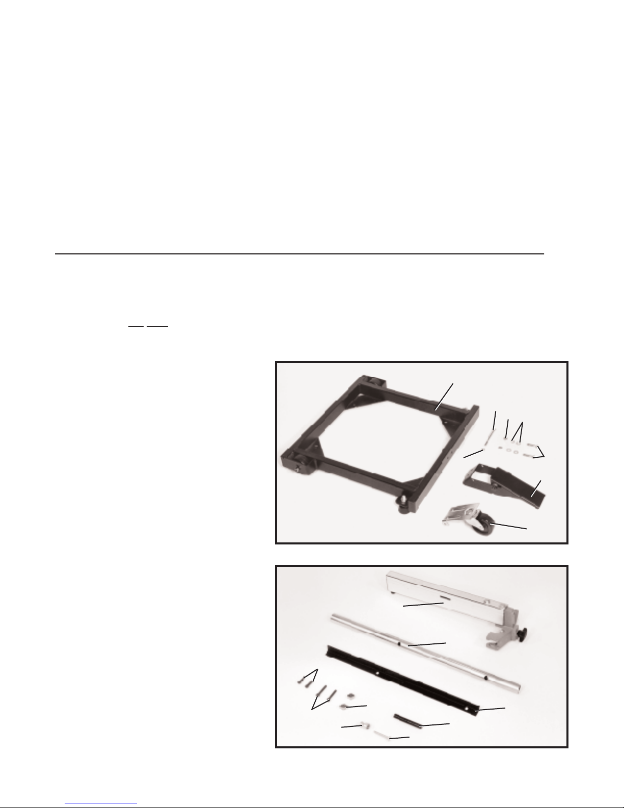
Carefully unp ack the band saw, stand, mobile base, and 12 cap acity rip fence from the shipping cont ainers. Remove
the protective coating from the machined surfaces of the band saw. This coating may be removed with a sof t cloth moist ened with kerosene ( D O NOT use acetone, gasoline or lacquer thinner for this purpose). Af ter cleaning, cover all unpainted surfaces with a good quality p aste wax. Fig. 2, illustrates the component s of the mobile base. Fig. 3, illustrates
the components of the rip fence.
1. Mobile base
2. 5/16-18 x 4 hex head screw
3. 5/16-18 locknut
4. 5/16 hex nut s (2)
5. Flat washers (4)
6. 5/16 x 1-1/2 hex head screws (2)
7. Bolt-on foot lever assembly
8. Caster assembly
1
2
4
5
6
7
3
8
1. 1/4-28 x 1 hex socket head screw (2)
2. 1/4-28 x 1-1/4 hex socket head screw (2)
3. S p acer (2)
4. Hand knob (For resawing operations)
5. 1/4-20 x 2 Round head screw
(For resawing operations)
6. Guide post (For resawing operations)
7. Rear rail
8. Front guide rail
9. Fence assembly
9
8
7
6
5
4
3
2
1
Fig. 2
Fig. 3
Page 5
5
Fig. 4
Fig. 5
Fig. 6
Fig. 7
B
A
C
D
E
G
J
F
K
H
A
F
B
A
L
M
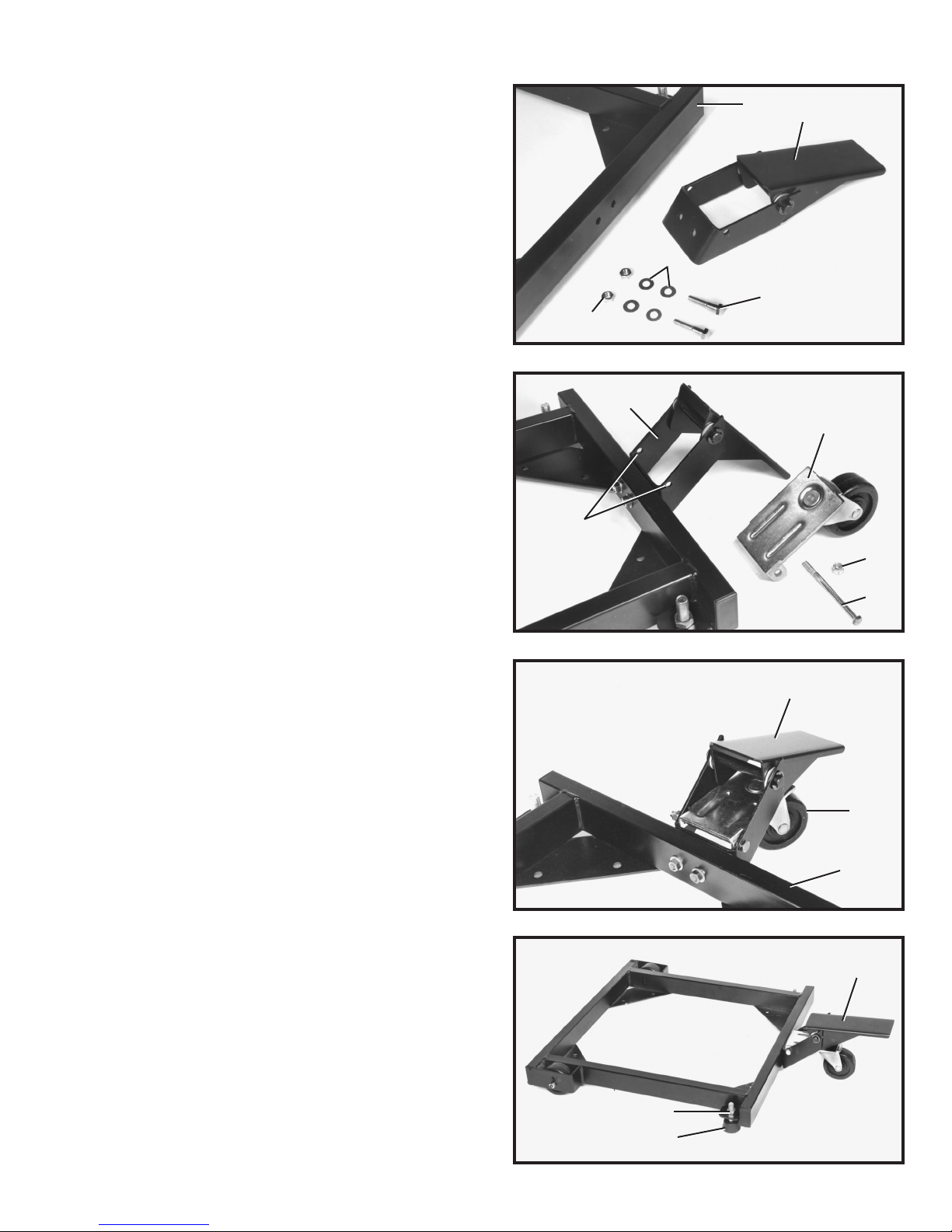
ASSEMBLING THE MOBILE BASE
The mobile base is constructed of heavy gage steel with
welded joint s and features a bolt-on foot lever assembly,
single swivel caster , and rigid wheels. T wo adjust able
foot p ads opposite the rigid wheels assure st able fourcorner cont act when the base is lowered. A convenient
foot-operated control lever raises and lowers the base for
easy movement for cleaning and repositioning.
3. Fig. 6, illustrates the caster assembly (F) and foot
lever assembly (A) fastened to the mobile base (B).
4. W ith the foot lever (A) Fig. 7, in the raised position
as shown, the mobile base should be level with the floor
surface and the two rubber feet, one of which is shown
at (L), should cont act the floor surface. To adjust the rub ber feet, tighten and loosen the hex nut, which is shown
at (M) and the nut which is located directly above the
rubber feet.
5. IMPORTANT:WHENPLACING THE MACHINE ON
THE MOBILE BASE, MAKE CERTAIN FOOT LEVER
(A) F I G . 7, IS IN THE RAISED POSITION A S SHOWN
TO AVOID MOVEMENT OF THE MOBILE BASE.
2. Assemble caster assembly (F) Fig. 5, to mobile base
bracket (G) using the four inch-long screw (H) through
two holes (J) in mobile base bracket (G) and two holes in
caster assembly (F). Fasten in place using locknut (K).
1. Assemble foot lever assembly (A) Fig. 4, to the out side of mobile base (B) with two 1-1/2 inch-long hex head
screws (C), four flat washers (D), and two hex nut s (E).
Page 6
6
Fig. 8
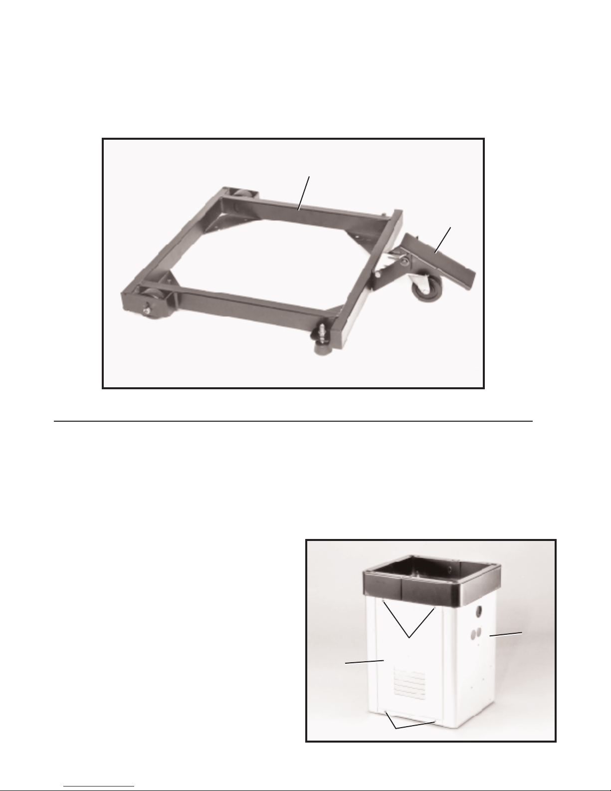
RAISING A N D LOWERING THE MOBILE BASE
1. To raise the mobile base (B) Fig. 8, and allow movement to a new location, push foot lever (A)
downward until the foot lever locks into position.
2. To lower the mobile base (B) Fig. 8, so it is supported by the floor surface, flip foot lever (A) upward.
3. IMPORTANT:TO AVOID PERSONAL INJURY, ALW AYS OPERATE THE MACHINE WITH THE
FOOT LEVER (A) IN THE RAISED POSITION A S SHOWNIN FIG. 5.
B
A
ASSEMBLING THE BAND SAW
The st and is shipped top down inside the shipping cont ainer with the motor mounted to the inside top
of the st and. The on/off switch is wired to the end of the power cord.
The motor must be removed from the inside top of the st and and reassembled to the horizont al mount ing bars inside the st and as follows:
1. Remove the stand (A) Fig. 9, from the shipping con -
tainer being careful not to crimp the switch cord which
extends through the top of the st and. NOTE: Set the
st and on several blocks of wood to raise the st and of f the
floor surface.
2. Remove panel (B) Fig. 9, from st and (A) by removing
two screws (C) and loosening two screws (D). Remove
p anel on opposite side of st and in the same manner.
Fig. 9
D
A
C
B
Page 7

7
3. Remove two mounting screws, one of which is
shown at (E) Fig. 10, that are holding motor (F) to the top
of st and (A ). IMPORTANT:D O NOT REMOVECABLE
TIE (G) T H AT IS HOLDING SWITCH CORD(H) TO VERTICAL MOUNTING BAR (J), UNLESS Y O U A R E USING
THEACCESSORY 28-984 HEIGHT ATTACHMENT O N
THE BAND SAW .THIS CABLE TIE (G),WILL KEEP
THE SWITCH CORD (H) FROM CONTACTING TH E
M O TO R PULLEY O R BELT DURING OPERATION.
Fig. 10
Fig. 1 1
Fig. 12
ASSEMBLING
MOTO RTO STAND
1. To make the motor assembly easier, turn stand (A)
Fig. 1 1, on it s side with two horizont al bars (B) down as
shown.
2. Position motor (C) Fig. 1 1, on two horizont al support
bars (B) as shown, and fasten with four 3/4 long carriage
bolt s, two of which are shown at (D), and four flanged nut s.
IMPORTANT:MA K E CERTAIN M OTOR SHAFT (E) IS
O N THE SAMESIDE OF THESTAND AS THELARGE
OPENING IN THE TO P O F TH E S TA N D BEFORE TIGHTENING CARRIAGE B OLTS (D). Further motor alignment
will be necessary af ter band saw is fastened to st and.
Fig. 13
3. Insert power cord plug (G) Fig. 12, through the bottom hole of the band saw st and to the out side of the st and.
4. Carefully turn the st and right side up.
IMPORTANT:Before assembling the band saw to the stand, we suggest that you place the st and (A) Fig. 13, onto
the mobile base (B), with the foot pedal lever (C) in the raised position as shown, so the wheels (D) and
rubber feet (E) are in full cont act with the floor surface.
A
C
E
D
B
G
Page 8

8
Fig. 14
Fig. 15
Fig. 16
B
D
F
A
C
B
C
A
C
A
B
D
ASSEMBLING
M O TO R PULLEY
Assemble motor pulley (A) Fig. 14, to the motor shaf t
making cert ain set screw (B) in the motor pulley engages
with key (C) in motor shaf t.
ASSEMBLING BANDSAW
TO STAND
1. Carefully place the band saw (A) Fig. 15, onto the
band saw st and (B). NOTE: Position the band saw so the
pulley (C) is over the opening (D) in the st and.
2. Align the four holes in the base of the band saw with
the four mounting holes in the top of the st and and
fasten the band saw to the st and with four 5/16-18 x
1-3/4 hex head screws, three of which are shown at (E)
Fig. 15, with flat washers and flange nut s.
ASSEMBLING AN D
ALIGNING V-BELT;
ADJUSTING BELT TENSION
1. Using a straight edge, align motor pulley (A) Fig. 16,
to the driven pulley (B). If necessary, both pulleys can be
adjusted inward or outward. The motor (C) can also be
adjusted on the motor mounting bars (D).
2. Assemble the V-belt (E) Fig. 16, to pulleys (A) and
(B) and adjust the belt tension by raising or lowering the
motor (C) on the motor mounting bars (D). If necessary,
the motor mounting bars (D) can be repositioned on two
vertical post s (F). NOTE: Make certain the pulleys are
kept in alignment when doing this. Correct belt tension is
obt ained when there is approximately 1 deflection, using
light finger pressure at the centersp an of the pulleys.
E
E
E
Page 9

9
Fig. 17
Fig. 18
ASSEMBLING BELT
A N D PULLEY GUARD
Assemble belt and pulley guard (A) Fig. 17, to the top of
the st and and surrounding the driven pulley with two
3/4-20 x 5/8 hex head screws, flat washers and hex
nut s (B).
ASSEMBLING SWITCH
1. MAKE CERTAIN THE BAND SAW IS DISCONNECTED FROMTHE POWER SOURCE.
2. CAUTION: T H E ON/OFF SWITCH-TO-MOTO R
CORD (F) FIG. 18, IS TIED TO VERTICAL MOUNTING
POST (G) OPPOSITE THE M O TO R PULLEY.THIS
CABLE TIE (H)PREVENTS THE SWITCH-TO-MOTO R
CORD(F), FROM CONTACTING THE BELT O R M O TO R
PULLEY DURING OPERATION. IMPORTA N T:D O N O T
REMOVE THIS CABLE TIE UNLESS Y O U A R E USING
THE ACCESSORY #28-984 HEIGHT ATTACHMENT
WITH THE BAND SAW .
3. Remove two outer hex nuts and lock washers (A)
Fig. 19, from the two screws extending out from the back
of the switch box (B).
4. Insert two screws (C) Fig. 19, located on back of
switch box, into two holes (D) located in the band saw
arm.
5. Fasten the switch box (B) to the band saw arm using
two hex nut s and lockwashers (A) Fig. 20, which were removed in STEP 3.
Fig. 19 Fig. 20
B
A
C
D
A
B
Page 10

10
6. Remove screw and cable clamp (E) Fig. 21, from
lower arm of band saw.
7. Insert switch cord (F) Fig. 21, into clamp (E) which
was removed in STEP 6, and fasten switch cord (F) to
band saw as shown. IMPORTA N T:CHECK AND MAKE
CERTAIN THE ON/OFF SWITCH-TO-MOTOR CORD
(F) F I G . 18, IS NOT CONTACTING M O TO R PULLEY O R
BELT.ADJUST C O RD (F) FIG.18,IF NECESSARY,
THEN TIGHTEN CABLE TIE (H).
Fig. 21
ASSEMBLING RIP FENCE
1. MAKE CERTAIN THE MACHINE IS DISCON-
NECTED FROMTHE POWER SOURCE.
2. Assemble rear guide rail (A) Fig. 22, to band saw
table using 1/4-28 x 1 hex socket head screws (B), at
locations (C). Do not completely tighten hardware at this
time.
3. Assemble front guide rail (D) Fig. 23, to band saw
table using 1/4-28 x 1-1/4 hex socket head screws (E),
and spacers (F), at locations (G). Position sp acers
between t able and guide rail.
Fig. 22
A
B
B
C
Fig. 23
F
F
E
D
G
E
E
F
Page 11

11
Fig. 24 Fig. 25
Fig. 26
5. Insert fence assembly (H) Fig. 25, onto front guide
rail (D). NOTE: Fence assembly (H) will clamp to the
front guide rail only, and simply rest on the rear
guide rail .
6. Determine if the gap between the bottom of fence
(H) Fig. 26, and the top of the saw t able is the same
across the entire length of fence. Fig. 26, illustrates a
fence which is improperly adjusted. If an adjustment is
necessary, the rear fence rail (A) Figs. 26 and 27, has
vertical slot s to allow for height adjustment s.
7. Fig. 27, illustrates a properly adjusted fence (H).
T ighten screws ( C ) Figs. 26 and 27, af ter adjustment s are
made.
D
H
A
C
H
Fig. 27
A
C
H
Fig. 28
H
L
K
J
8. Position the fence assembly (H) Fig. 28, at one edge
of the miter gage slot (J), as shown. T ighten knob (K).
Check to see that the fence assembly is p arallel to the
miter gage slot. If an adjustment is necessary, loosen two
hex head screws (L), and adjust fence assembly so it is
p arallel to the miter gage slot. T ighten screws (L).
4. Fig. 24, illustrates the front and rear guide rails
mounted to the band saw t able.
Page 12

12
Fig. 29
9. Position a combination square (M) Fig. 29, against the side of fence assembly (H), as shown.
T ighten knob (K). Check to see that the fence assembly is perpendicular to the band saw t able. If an
adjustment is necessary, loosen two hex socket head screws (E), and adjust the position of front
guide rail (D). T ighten screws (E).
10. Position the fence assembly (H) Fig. 29, against the saw blade. T ighten knob (K). Check to
see that the pointer (N) is aligned with the 0 (zero) marking on the front guide rail (D). If an adjust ment is necessary, loosen the pointer screw and adjust the pointer. T ighten pointer screw .
H
E
D
K
E
N
M
CONNECTING BAND SAW TO POWERSOURCE
POWERCONNECTIONS
A s e p arate electrical circuit should be used for your tools. This circuit should not be less than #12
wire and should be protected with a 20 Amp fuse. Have a certified electrician replace or rep air a
worn cord immediately. Before connecting the motor to a power line, make sure the switch is in
the OFF position and be sure that the electric current is of the same characteristics as st amped
on the motor nameplate. Running on low volt age will damage the motor .
W ARNING:D O NOT EXPOSE THE TOOL TO RAIN O R OPERATE THE TOOL IN DAMP
LOCATIONS.
M O TO R SPECIFICATIONS
Y our saw is wired for 110-120 volt, 60 HZ alternating current. Before connecting the saw to the
power source, make sure the switch is in the OFF position.
Page 13

13
Fig. 31Fig. 30
GROUNDED OUTLET BO X
CURRENT
CARRYING
PRONGS
GROUNDED OUTLET BO X
GROUNDING MEANS
ADAPTER
CAUTION: IN ALL CASES, MAKE CERTAIN THE RECEPTACLE IN QUESTION IS PROPERLY GROUNDED.
IF Y O U A R E N O T SURE, H AVE A CERTIFIED ELECTRICIAN CHECK THE RECEPTACLE.
This tool is intended for use on a circuit that has an outlet
and a plug that looks like the one shown in Fig. 30. A
temporary adapter, which looks like the adapter illustrated
in Fig. 31, may be used to connect this plug to a 2-pole
recept acle, as shown in Fig. 31, if a properly grounded
outlet is not available. The temporary adapter should be
used only until a properly grounded outlet can be inst alled by a qualified electrician. THIS ADAPTER IS
N O T APPLICABLE IN CANADA. The green-colored
rigid ear , lug, and the like, extending from the adapter
must be connected to a permanent ground, such as a
properly grounded outlet box, as shown in Fig. 31.
GROUNDING INSTRUCTIONS
CAUTION: THIS TO O L MUST BE GROUNDED WHILE IN US E
TO PROTECT THE OPERATO R FROM ELECTRIC SHOCK.
In the event of a malfunction or breakdown, grounding
provides a p ath of least resist ance for electric
current to reduce the risk of electric shock. The motor is
equipped with an electric cord having an equipmentgrounding conductor and a grounding plug. The plug
must be plugged into a matching outlet that is properly
inst alled and grounded in accordance with all local codes
and ordinances.
Do not modify the plug provided - if it will not fit the outlet,
have the proper outlet inst alled by a qualified electrician.
Improper connection of the equipment-grounding conduc tor can result in risk of electric shock. The conductor with
insulation having an outer surface that is green with or
without yellow stripes is the equipment-grounding conduc tor. If rep air or replacement of the electric cord or plug is
necessary, do not connect the equipment grounding con ductor to a live terminal.
Check with a qualified electrician or service personnel if
the grounding instructions are not completely under stood, or if in doubt as to whether the tool is properly
grounded.
Use only 3-wire extension cords that have 3-prong
grounding type plugs and 3-hole recept acles that accept
the tool s plug, as shown in Fig. 30.
R e pair or replace damaged or worn cord immediately.
GROUNDING BLADE IS
LONGEST O F THE THREE BLADES
TO TAL LENGTH OF GAGEOF EXTENSION
CORDIN FEET CORDTO USE
EXTENSION CORDS
Use proper extension cords. Make sure your extension
cord is in good condition and is a 3-wire extension cord
which has a 3-prong grounding type plug and a 3-hole
recept acle which will accept the tool s plug. When using
an extension cord, be sure to use one heavy enough to
carry the current of the band saw. An undersized cord will
cause a drop in line volt age resulting in loss of power and
overheating. Fig. 32 shows the correct size to use depending on cord length. If in doubt, use the next heavier
gage. The smaller the gage number, the heavier the cord.
Fig. 32
0 - 25
26 - 50
51 - 100
101 - 150
16 A W G
16 A W G
14 A W G
12 A W G
Page 14

14
Fig. 33
Fig. 34
Fig. 35
Fig. 36
OPERATING CONTROLS AND ADJUSTMENTS
STARTING A N D
STOPPING THE SAW
1. The on/of f switch is located under the switch shield
(A) Fig. 33. To turn the band saw ON , move switch
trigger (B) upward to the ON position.
LOCKING SWITCH
IN T H E OFF POSITION
W e suggest that when the band saw is not in use, the
on/of f switch trigger be locked in the OFF position using
a padlock (C) Fig. 35, through the two holes in the switch
plate, as shown in Fig. 35. NOTE: Padlock shown is
available as accessory model 50-325.
2. To turn the band saw OFF , simply push down on
the switch shield (A) Fig. 34.
TABLE INSERT
Place t able insert (A) Fig. 36, into the hole provided in
the table surface, making cert ain the pin (B) in the t able
engages one of the indent s in the t able insert.
A
B
A
C
Page 15

15
Fig. 37
Fig. 38
Fig. 39
ADJUSTING TABLE STO P
The band saw is equipped with an adjust able t able stop
(B) Fig. 38, that allows the t able to be set perfectly at
90 degrees with the blade.
Tilt the t able to the lef t until the t able stop (B) Fig. 38,
cont act s the bottom of the t able. Place a square on the
table and against the blade as shown in Fig. 39, and
check to see if the blade is 90 degrees to the t able sur face. If an adjustment is necessary, proceed as follows:
1.Tilt the t able slightly to the right and tighten t able lock
knobs.
2. T urn adjustment nut (C) Fig. 38, right or lef t as nec essary to raise or lower t able stop (B).
3. Lower the t able and make cert ain the t able is
90 degrees to the blade as shown in Fig. 39.
4. It is necessary to remove the adjust able t able stop
(B) Fig. 38, when tilting the t able to the lef t.
TILTING THE TABLE
1. The t able on the band saw can be tilted 45 degrees
to the right and 10 degrees to the lef t. To tilt the t able to
the right, loosen two locking knobs (A) Fig. 37, tilt the
table to the desired angle as shown on scale (D), and
tighten two locking knobs (A).
2.To tilt the t able to the lef t, loosen two locking knobs
(A) Fig. 37, and tilt the t able slightly to the right until you
can gain access to t able stop (B) Fig. 38. Remove t able
stop (B) Fig. 38, and tilt the t able to the lef t angle up to
10 degrees and tighten two locking knobs (A) Fig. 37.
A
D
A
C
B
Page 16

16
Fig. 40
Fig. 41
Fig. 42
TRACKING THE BLADE
DISCONNECT MACHINE FROMPOWER SOURCE.
IMPORTANT:Before tracking the blade, make sure the
blade guides and blade support bearings are clear of the
blade so as not to interfere with the tracking adjustment.
Af ter tension has been applied to the blade, revolve the
wheels slowly forward by hand and watch the blade (A)
Fig. 41, to see that it travels in the center of the upper
tire. If the blade begins to creep toward the front edge,
loosen the wing nut (B) Fig. 42, and tighten the thumb
screw (C). This will tilt the top of the wheel toward the
back of the machine and will draw the blade toward the
center of the tire. If the blade creep s toward the back
edge, turn the thumb screw in the opposite direction.
Adjust the thumb screw (C) Fig. 42, only a fraction of a
turn at a time. NEVER TRACK THE BLADE WHILE
THE MACHINE IS RUNNING. Af ter the blade is tracking
in the center of the tires, tighten the wing nut (B) Fig. 42.
ADJUSTING
BLADE TENSION
DISCONNECT MACHINE FROM POWER SOURCE.
On the back of the upper wheel slide bracket, there is a
series of graduations. These indicate the proper tension
for various wid ths of blades. W ith the blade on the
wheels, turn the knob (A) Fig. 40, to raise or lower the
wheel, until the red fiber washer (B) is in line with the
proper graduation for the size of blade being used.
The graduations will be found correct for average work,
and are not af fected by rebrazing of the saw blade. W e
urge you to use these graduations until you have
become familiar enough with the operation of the Band
Saw to vary the tension for dif ferent kinds of blades or
work. Over-straining is a common cause of blade break age and other unsatisfactory blade performance. Release the tension when the machine is not in use.
C
Page 17

17
ADJUSTING UPPER BLADE
GUIDES AND BLADE
SUPPORT BEARING
DISCONNECT MACHINE FROMPOWER SOURCE.
The upper blade guides and blade support bearings are
adjusted only af ter the blade is tensioned and tracking
properly. To adjust proceed as follows:
1. The upper blade guides (A) Fig. 45, are held in place
by means of the set screws (B). Loosen the set screws
(B) to move the guides (A) as close as possible to the
side of the blade, being careful not to pinch the blade.
Then tighten the screws (B).
2. The guides (A) Fig. 45, should then be adjusted so
that the front edge of the guides are just behind the
gullet s o f the saw teeth. The complete guide block
bracket can be moved in or out by loosening thumb
screw (C) and turning knurled knob (D) Fig. 45. When
guides (A) are set properly, tighten thumb screw (C).
3. The upper blade support bearing (E) Fig. 45, pre vent s the blade from being pushed too far to the rear
which could damage the set in the saw teeth. The sup port bearing (E) should be set 1/64 behind the blade by
loosening thumb screw (F) and turning knurled knob (G)
to move the support bearing (E) in or out.
4. The blade support bearing (E) should also be adjust ed so the back edge of the blade overlap s the out side
diameter of the ball bearing by about 1/16 . The bearing
(E) is set on an eccentric and to change position remove
screw (H) and bearing (E) Fig. 45. Loosen thumb screw
(F), back out screw (G) and re-position shaf t that bearing
(E) is att ached to.
Fig. 43
ADJUSTING UPPER BLADE
GUIDE ASSEMBLY
DISCONNECT MACHINE FROMPOWER SOURCE.
The upper blade guide assembly (A) Fig. 43, should
always be set as close as possible to the top surface of
the material being cut by loosening lock knob (B) a nd
moving the guide assembly (A) to the desired position.
The upper blade guide assembly should also be adjust ed so that the blade guides (A) Fig. 44, are flat with the
blade. If an adjustment is necessary, loosen screw (B)
and rot ate the complete guide assembly (C) until the
blade guides are flat with the blade.
Fig. 44
Fig. 45
Page 18

18
ADJUSTING LOWER BLADE
GUIDES AND BLADE
SUPPORT BEARING
DISCONNECT MACHINE FROMPOWER SOURCE.
The lower blade guides and blade support bearing
should be adjusted at the same time as the upper guides
and bearing as follows:
1. Loosen the two screws (A) Fig. 46, and move the guides
(B) as close as possible to the side of the blade, being care ful not to pinch the blade. Then tighten screws (A).
2. The front edge of the guide blocks (B) should be adjust ed so they are just behind the gullets of the saw teeth
by turning the knurled knob (C) Fig. 46.
3. The lower blade support bearing (D) Fig. 46, should
be adjusted so it is about 1/64 behind the back of the
blade by turning the knurled knob (E).
Fig. 46
D
C
E
A
B
A
CHANGING THE BLADE
MAKE CERTAIN THE MACHINE IS DISCONNECTED FROM THE POWERSOURCE.
NOTE: Blades for the 14 band saw are 93-1/2 in length
1. Open the upper and lower wheel guards.
2. Release tension on the band saw blade.
3. Remove the table adjustment pin and t able insert.
4. Slide the saw blade of f the wheel and guide it out
through the slot in the t able.
5. T o inst all the new saw blade, reverse the above pro cedure. NOTE: Blade teeth should be pointing down ward at the front of the t able.
BAND SAW BLADES
A band saw blade is a delicate piece of steel that is sub jected to tremendous strain. Y ou can obt ain long use
from a band saw blade if you give it fair treatment. B
ensure you use blades of the proper thickness, wid th,
and temper for the various types of material to be cut.
Always use the widest blade possible. Use the narrow
blades only for sawing small, abrupt curves and for fine
delicate work. This will save blades and will produce
better work. Band saw blades may be purchased, welded, set and sharpened ready for use. For cutting wood
and similar materials, we can supply them in wid ths of
1/8, 3/16, 1/4, 3/8, 1/2, and 3/4 inches.
File and set the wood cutting blades whenever you find it
requires pressure to make them cut. If a blade is broken
it can be brazed or welded; however, if it has become
badly work-hardened, it will soon break in another place.
If you are not equipped to file, set and braze or weld
blades, t ake them to a saw filer for reconditioning. Under
average conditions, blades should be resharpened af ter
4 hours of operation.
Any one of a number of conditions may cause a band
saw blade to break. Blade breakage is, in some cases,
unavoidable, being the natural result of the peculiar
stresses to which such blades are subjected. It is, how ever, of ten due to avoidable causes, most of ten to lack of
care or judgment on the p art of the operator in mounting
or adjusting the blade or guides. The most common
causes of blade breakage are: (1) faulty alignment s and
adjustments of the guides; (2) forcing or twisting a wide
blade around a curve of short radius; (3) feeding too fast;
4) dullness of the teeth or absence of suf ficient set;
(5) excessive tightening of the blade; (6) top guide set
too high above the work being cut; (7) using a blade with
a lumpy or improperly finished braze or weld; and (8)
continuous running of the saw blade when not in use for
cutting.
New blades for the st andard 14-inch Band Saw are
93-1/2 inches long. The adjustment will accommodate
blades up to a maximum length of 94 inches and to a
minimum length of 91-1/2 inches. When equipped with
the No. 28-984 Height Att achment, new blades should be
105 inches long; maximum and minimum lengths are
106 and 103-1/2 inches.
Page 19

19
OPERATING T HE BAND SAW
Before st arting the machine, see that all adjustment s are
properly made and the guards are in place. T urn the
pulley by hand to make sure that everything is correct
BEFORE turning on the power.
Keep the top guide down close to the work at all times.
Do not force the material against the blade too hard.
Light cont act with the blade will permit easier following of
the line and prevent undue friction, heating, and work-
hardening of the blade at it s back edge.
KEEP THE SAW BLADE SHARP and you will find that
very little forward pressure is required for average cut ting. Move the stock against the blade steadily and no
faster than will give an easy cutting movement.
A void twisting the blade by trying to turn sharp corners.
Remember, you must saw around corners.
CUTTING C U RVES
When cutting curves, turn the stock carefully so that the
blade may follow without being twisted. If a curve is so
abrupt that it is necessary to repeatedly back up and cut
a new kerf, either a narrow blade is needed or a blade
with more set is required. The more set a blade has, the
easier it will allow the stock to be turned, but the cut is usu ally rougher than where a medium amount of set is used.
In withdrawing the piece being cut, in order to change the
cut, or for any other reason, the operator must be careful
that he does not accident ally draw the blade of f the
wheels. In most cass it is easier and safer to turn the
stock and saw out through the waste material, rather
than try to withdraw the stock from the blade.
Fig. 49Fig. 48
O
P
H
Fig. 47
S
P
O
H
RESAWING OPERATIONS
1. MAKE CERTAIN THE MACHINE IS DISCONNECTED FROMTHE POWER SOURCE.
2. Thread knob (P) Fig. 47, onto 2 long screw (S) and
tighten with a flat-bladed screwdriver .
3.Att ach guide post (O) Fig. 48, to either side of rip
fence assembly (H) with hand knob assembly (P). Position the guide post (O) on the fence assembly so it is
centered with the front edge of the blade. This will pro vide better control while performing intricate cut s.
4. Fig. 49, illustrates a typical resawing operation using
the guide post (O) assembled to the rip fence.
If a number of identically shaped thin pieces are required,
the easiest way to make them is the resawing technique.
In this operation the face of the rip fence can be used, or
to have more control when working with irregular shaped
pieces, a guide post can be used on either side of the
rip fence. T o assemble the guide post to the rip fence,
proceed as follows:
O
Page 20

20
Delt a will rep air or replace, at it s expense and at it s option, any Delt a machine, machine part, or
machine accessory which in normal use has proven to be defective in workmanship or material,
provided that the customer returns the product prepaid to a Delt a factory service center or authorized service st ation with proof of purchase of the product within two years and provides Delt a with
reasonable opportunity to verify the alleged defect by inspection. Delta may require that electric
motors be returned prepaid to a motor manufacturer s authorized station for inspection and repair
or replacement. Delta will not be responsible for any asserted defect which has resulted from nor mal wear, misuse, abuse or repair or alteration made or specifically authorized by anyone other
than an authorized Delta Service facility or representative. Under no circumst ances will Delt a be
liable for incident al or consequential damages resulting from defective product s. This warranty is
Delt a s sole warranty and sets forth the customer s exclusive remedy, with respect to defective
products; all other warranties, express or implied, whether of merchantability , fitness for purpose,
or otherwise, are expressly disclaimed by Delt a.
Delt a Building Trades and Home Shop Machinery
Two Y ear Limited Warranty
Printed in U.S.A.
PARTS, SERVICE O R W ARRANTY ASSISTANCE
All Delt a Machines and accessories are manufactured to
high quality st andards and are serviced by a network of
factory service centers and authorized service st ations
listed in your owner s manual. To obtain additional infor -
mation regarding your Delt a quality product or to obt ain
part s, service or warranty assist ance, please call or fax
Delt a s toll-free hotline number.
Delt a maint ains a modern,
ef ficient Part s Distribution
Center, maint aining an
inventory of over 15,000
part s located in Memphis,
Tennessee.
Highly qualified and experienced Customer Service
Representatives are st anding
by to assist you on weekdays
from 7:00 A.M. to 6:00 P.M.
Memphis time.
Memphis, TN 38118
4290 Raines Road
Phone: (901) 363-8800
800-223-PA R T
FAX: 800-535-6488
 Loading...