

Page 1
(Model 28-185)
DATED _23-95 PART NO _346498
Page 2

TABLE OF CONTENTS
SAFETY RULES ...................................................................................................................................... 3
ADDiTiONAL SAFETY RULES FOR BAND SAWS ............................................................................... 4
UNPACKING ........................................................................................................................................... 5
ASSEMBLY iNSTRUCTiONS ................................................................................................................. 5
Assembling Rip Fence To Table ................................................................................................... 6
Fastening Band Saw To Supporting Surface ............................................................................... 7
CONNECTING BAND SAW TO POWER SOURCE
Power Connections ........................................................................................................................ 7
Motor Specifications ....................................................................................................................... 7
Extension Cords ............................................................................................................................. 7
Grounding instructions .................................................................................................................. 8
OPERATING CONTROLS AND ADJUSTMENTS
Starting And Stopping Saw ........................................................................................................... 9
Locking Switch in The "Off" Position ........................................................................................... 9
Opening And Closing Hinged Door .............................................................................................. 9
Adjusting Blade Tension .............................................................................................................. 10
Tracking The Blade ....................................................................................................................... 10
Adjusting Upper Blade Guide Assembly .................................................................................... It
Adjusting Upper Blade Guides .................................................................................................... 11
Adjusting Upper Blade Support Bearing .................................................................................... 11
Adjusting Lower Blade Guides And Guide Bracket .................................................................. 12
Rip Fence Operation And Adjustments ...................................................................................... 12
Tilting The Table ........................................................................................................................... 13
Leveling The Table ....................................................................................................................... 13
Changing Blades .......................................................................................................................... 13
Miter Gage ..................................................................................................................................... 13
Dust Chute ..................................................................................................................................... 14
Wrench Holder .............................................................................................................................. 14
Blade And Wheel Brush ............................................................................................................... 14
WARRANTY .......................................................................................................................................... 14
Page 3
SAFETY RULES
Woodworking canbe dangerous ifsafe and proper operating procedures are not followed. As with all machinery, there are certain
hazards involved with the operation of the product. Using the machine with respect and caution will considerably lessen the
possiblity of personal injury. However, ifnormal safety precautions are overlooked or ignored, personal injuryto theoperator may
result. Safety equipment such as guards, push sticks, hold-downs, featherboards, goggles, dust masks and hearing protection
can reduce your potential for injury. But eventhe best guard won't make up for poor judgment, carelessness or inattention.
use common sen_ and exercise caution inthe workshop. Ifa procedure feels dangerous, don't try it. Figure out an alternative
procedure that feels safer. REMEMBER: Your personal safety is your responsibility.
This machine was designed forcertain applications only. Delta Machinery strongly recommends that this machine not be modified
and/or used for any application other than that for which it was designed. If you have any questions relative to a particular
application, DO NOT use the machine until you have first contacted Delta to determine ifit can or should be performed on the
product.
DELTA iNTERNATIONAL MACHINERY CORP.
MANAGER OF TECHNICAL SERVICES
246 ALPHA DRIVE
PmTTSBURGH, PENNSYLVANIA 15238
(iN CANADA: 644 iMPERIAL ROAD,GUELPH, ONTARIO N1H 6M7)
WARNING: FAILURE TO FOLLOW THESE RULES
MAY RESULT iN SERIOUS PERSONAL iNJURY
1. FOR YOUR OWN SAFETY, READ iNSTRUCTiON
MANUAL BEFORE OPERATING THE TOOL. Learn the
tool's application and limitations as well asthe specific hazards
peculiar to it.
2. KEEP GUARDS iN PLACE and in working order.
3. ALWAYS WEAR EYE PROTECTION.
4. GROUND ALL TOOLS. If tool is equipped with three-
prong plug,it should be plugged into a three-hole electrical
receptacle, ifanadapter is usedto accommodate a two-prong
receptacle, the adapter lug must be attached to a known
ground. Never remove the third prong.
5. REMOVE ADJUSTING KEYS AND WRENCHES. Form
habit of checking to see that keys and adjusting wrenches are
removed from tool before turning it "on."
6. KEEP WORK AREA CLEAN. Cluttered areas and
benches invite accidents.
7. DON'T USE iN DANGEROUS ENVIRONMENT. Don't
use power toolsin damp or wet locations, or expose them to
rain. Keep work area well-lighted.
8. KEEP CHILDREN AND VISITORS AWAY. All children
and visitors should be kept a safe distance from work area.
9. MAKE WORKSHOP CHILDPROOF - with padlocks,
master switches, or by removing starter keys.
10. DON'TFORCETOOL. Itwiltdothejobbetterandbesafer
at the rate for which it was designed.
11. USE RIGHT TOOL. Don't force tool or attachment to do
a job for which it was not designed.
12. WEAR PROPER APPAREL. No loose clothing, gloves,
neckties, rings, bracelets, or other jewelry to get caught in
moving parts. Nonslip footwear is recommended. Wear
protective hair covering to contain long hair.
13. ALWAYS USE SAFETY GLASSES. Wear safety glasses
(must comply with ANSI Z87.1). Everyday eyeglasses only
have impactresistant lenses; they are notsafety glasses. Also
use face or dust mask ifcutting operation is dusty.
14. SECURE WORK. Use clamps or a vise to hold work when
practical. It'ssafer than using your hand and frees both hands
to operate tool.
15. DON'T OVERREACH. Keep proper footing and balance
at all times.
16. MAiNTAiN TOOLS IN TOP CONDiTiON. Keep tools
sharp and clean for best and safest performance. Fellow
instructions for lubricating and changing accessories.
17. DISCONNECT TOOLS before servicing and when
changing accessories such as blades, bits, cutters, etc.
18. USE RECOMMENDED ACCESSOR|ES. The use of
improperaccessories may cause hazards or risk of injury to
persons.
19. REDUCE THE RaSK OF UNiNTENTiONAL START-
iNG, Make sure switch is in"OFF" position before plugging in
power cord.
20. NEVER STAND ON TOOL. Serious injury could occur if
the tool istipped or ifthe cutting tool is accidentally contacted.
21. CHECK DAMAGED PARTS. Before further use of the
tool, a guard or other part that is damaged should be carefully
checked to ensure that itwill operate properly and perform its
intended function - check for alignment of moving parts,
binding ofmoving parts, breakage of parts, mounting, andany
other conditions that may affect itsoperation= A guard or other
part that is damaged should be properly repaired or replaced.
22. DiRECTiON OF FEED. Feed work into a blade or cuttter
against the direction of rotation of the blade or cutter only.
23. NEVER LEAVETOOL RUNN|NG UNATTENDED. TURN
POWER OFF. Don't leave tool until it comes to a complete
stop.
24. DRUGS, ALCOHOL, MEDiCATiON. Do not operate tool
while under the influenceof drugs, alcohol or any medication.
25. MAKE SURETOOL ISD|SCONNECTED FROM POWER
SUPPLY while motor is being mounted, connected or
reconnected.
26. WARNING: The dust generated by certain woods and
wood products can be injurious to your health. Always operate
machinery in welt ventilated areas and provide for proper dust
removal. Usewood dustcollection systems whenever possible.
Page 4
ADDiTiONAL SAFETY RULES
FOR BAND SAWS
1, WARNING: Do not operate your band saw until it
is completely assembled and installed according to the
instructions.
2. iF YOU ARE NOT thoroughly familiar with the opera-
tion of band saws, obtain advice from your supervisor,
instructor, or other qualified person.
3. ALWAYS WEAR EYE PROTECTION.
4. MAKESURE the machine is fastenedto asupporting
surfaceto prevent itfrom tipping over duringoperation.
5. NEVER turn the machine "ON" before clearing the
table of all objects (tools, scrap pieces, etc.).
6. NEVER start the band saw with the saw blade pressed
against the workpiece.
7. ADJUST the upper guide about 1/8" above the
materia_being cut.
8. MAKE SURE that blade tension and blade tracking
are properly adjusted.
9. ALWAYS keep hands and fingers away from the
blade.
10. CHECK for proper blade size and type.
11, DO NOT attempt to saw stock that does not have a
flat surface, unless a suitable supportis used.
12. HOLD matedal firmly against the table and feed materiat
into blade at a moderate speed.
13. TURN OFF machine if the material is to be backed
out of an uncomp{eted cut.
14. MAKE "release" cuts before cutting long curves
16. STOP the machine before removing scrap pieces
from the table.
t7. NEVER perform layout, assembly, orset-up work on
the table while the machine is operating.
!8. ALWAYS hold the workpiece firmly against the table.
19. AVOID awkward hand positions where a sudden slip
could cause a hand to move into the blade.
20. DO NOT cut material that is too small to be safely
supported.
21. MAKE SURE the blade teeth point downward toward
the table.
22. ALWAYS maintain proper adjustment of blade
tension, bladeguides, and blade support bearing.
23. SHUT OFF the power and clean the table and work
area before leaving the machine.
24. SHOULD any part of your band saw be missing,
damaged, or fail in any way, or any electrical component
fail to perform properly, shut off switch and remove plug
from power supply outlet. Replace missing, damaged, or
failed parts before resuming operation.
25. THE USE of attachments and accessories not recom-
mended by Delta may result in the risk of injuries.
26. ADDITIONAL information regarding the safe and proper
operation of this product is available from the National
Safety Council, 1121 Spring Lake Drive, Itasca, IL 60143-
3201, in the Accident Prevention Manual for Industrial
Operations and a_so{r_the Safety Data Sheets prov{ded by
the NSC. Please also refer to the American National
Standards Institute ANS_ 01.! Safety Requirements for
Woodworking Machinery and the U.S. Department of
Labor OSHA 1910.213 Regulations.
t5. DO NOT remove jammed cut-off pieces until blade
has stopped.
27. SAVE THESE INSTRUCTIONS. Refer to them often
and use them to instruct others.
Page 5
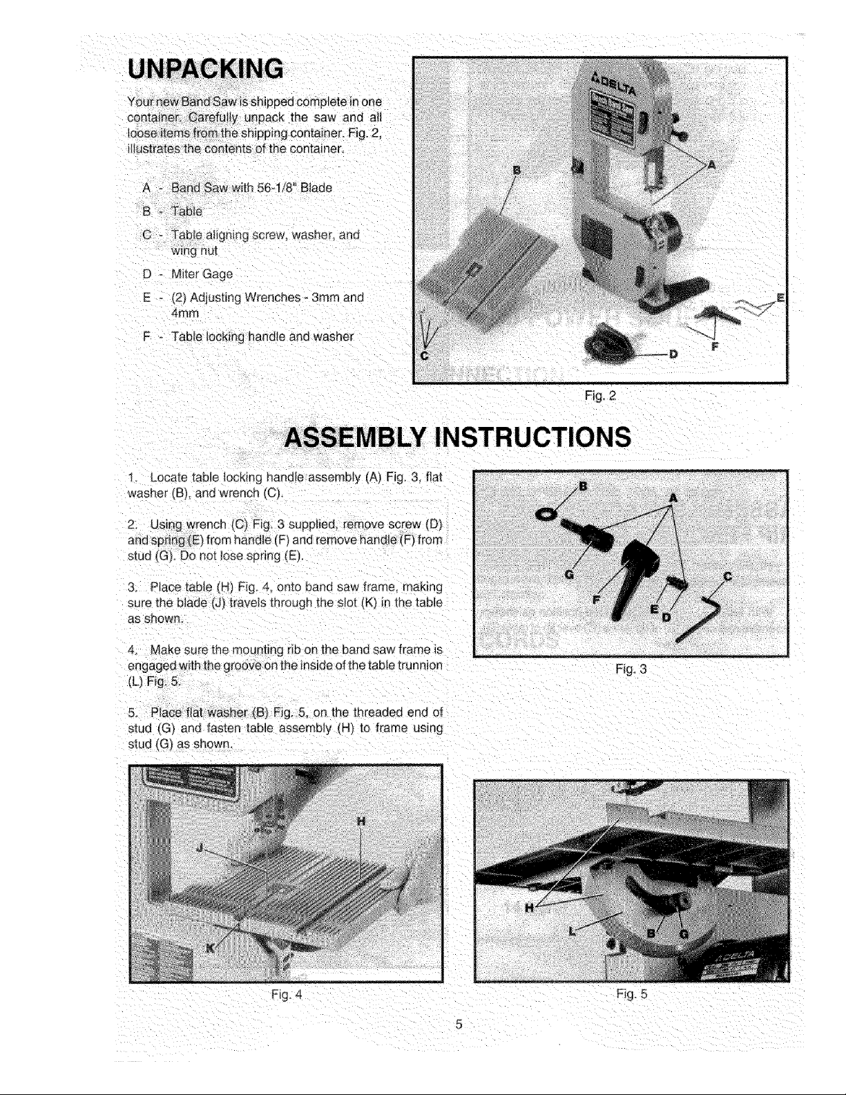
A - BandSawwLh56q/8Blade
B- Table
C - Tablealigningscrew_washer,ana
Wingnut
D ° Miter Gage
E _ _2)Adjusting Wrenches - 3ram and
4ram
F _ Table locking handle and washer
ASSEMBLY INSTRUCTIONS
. Locate table locking handle assembly (A) Fig. & flat
washer _B), and wrench/C;
stuc tG} Do not lose spring (E).
3. Place table (H) Fig 4: onto band saw frame, making
sure me blade (J) t[avels through the slot (K) in the table
as shown-
Fig. 2
4. Make sure the mou r_t_ngrib on the band saw frame is
engaged with the groove on the inside of the table trunnion
_L) Fig. 5,
5, Place fiat washer (B) Fig, 5, on the threaded end of
stud tG'_ and fasten t&ble assembly (H_ to frame using
stud (G_,as shown.
Fi£ 4
Fig. 3
Fig. 5
Page 6

[. _L._: >&'_,bl - !.qble ,ock,qq h,;lndie (b F'g 6 c _' stud
._,d rup,_,ue bcu;w ',D} and _.prfng NOTE: Har]d_e iF) is
_,p-'g -,-_ded m,d , _'- Dr" reoos_b,,ned ,_n thr, st,J,d b_
p,,_ ¢,q o_4 rico .d_d,e ,-ii_d r_-,pos_,on_eg ¢,or',. tr_e stud
c:g _,
I
ASSEMBLING ACCESSORY
RIP FENCE TO TABLE
t[ Vou p lcl]:ppd th,: ArfusSory 28N81 Rip Ferir.e,
;J: _rq!,_ ttz bret41-1;, as f,3h,%,',,,.
as,;,:.ml, _ re :_r,,t,_m,p, B_ot uI_reqc_ C, c/_:.,r [,p sf t&bte [[.);
2 LO:,lurt_e [n,r,t of r b _e,_,L._.C.:£-1-_ O ,]ll_ltqbt '/'@t 1[o}#_
_','] p',_h down on ,,c¢:r_ i_wer ,A_ NOTE: Ciamp_u_
action on the r_p fe,_ce (C} F_g 9 can be ttqhlened or
13uberea _/ _4tr:g k,rk'nt_ ;ever tA_ arid "otatvrg tever
clockw!se or counterclockwise as necessar,! urfflJ hrm
c!d_p,n_ action ,9 accomot_shed Rto _eqce ;C_ car" be
positioned either to the light or left of the saw blade
F_q
F_g 9
Page 7

FASTENING BAND SAW
TO SUPPORTING SURFACE
ifduring operation there is any tendency for the machine to
tip over, slide, or walk on the supporting surface, the
machine must be secured to the supporting surface. Four
holes (A) Fig, 10, are provided inthe band saw base for this
purpose.
CONNECTING BAND SAW TO POWER SOURCE
POWER CONNECTIONS
Aseparate electrical circuit should be used for your tools. This circuit should not be less than #12 wire
and should be protected with a 20 Amp fuse. Have a certified electrician replace orrepair a worn cord
immediately. Before connecting the motorto a power line, make sure the switch isinthe"OFF" position
and be sure that the electric current is ofthe same characteristics as stamped on the motor nameplate.
Running on low voltage will damage the motor.
Fig. 10
WARNING: DO NOT EXPOSE THE TOOL TO RAIN OR OPERATE THE TOOL IN DAMP
LOCATIONS.
MOTOR SPECIFICATIONS
Your band saw is wired for 110-120 volt, 60 HZ alternating current. Before connecting the band saw
to the power source, make sure the switch is in the "OFF" position.
EXTENSION CORDS
Use proper extension cords. Make sure your extension cord is in good condition and is a 3-wire
extension cord which has a 3-prong grounding type plug and a 3-pote receptacle which will accept
the tools plug. When using an extension cord, be sure to use one heavy enough to carry the current
of the saw. An undersized cord will cause a drop in line voltage resulting in loss of power and
overheating. Fig. 10A, shows the correct gage to use depending on cord length. If in doubt, use the
next heavier gage, The smaller the gage number, the heavier the cord.
TOTAL LENGTH OF GAGE OF EXTENSION
CORD iN FEET CORD TO USE
0 25 18AWG
26 100 16AWG
101 150 14AWG
Fig. 10A
Page 8
GROUNDING iNSTRUCTiONS
CAUTION: THiS TOOL MUST BE GROUNDED WHILE iN USE TO PROTECT THE OPERATOR
FROM ELECTRIC SHOCK.
In the event of a malfunction or breakdown, grounding provides a path of least resistance for
electric current to reduce the risk of electric shock. This tool is equipped with an electric cord
having an equipment-grounding conductor and agrounding plug. The plug must be plugged into
a matching outlet that is properly installed and grounded in accordance with all local codes and
ordinances.
Donot modifytheplug provided- if itwillnotfit theoutlet, havethe properoutlet installedbya
qualified electrician.
Improper connection of the equipment-grounding conductor can result in risk of electric shock.
The conductor with insulation having an outer surface that isgreen with or without yellow stripes
is the equipment-grounding conductor. If repair or replacement of the electric cord or plug is
necessary, do not connect the equipment grounding conductor to a live terminal.
Check with a qualified electrician or service personnel if the grounding instructions are not
completely understood, or if in doubt as to whether the tool is properly grounded.
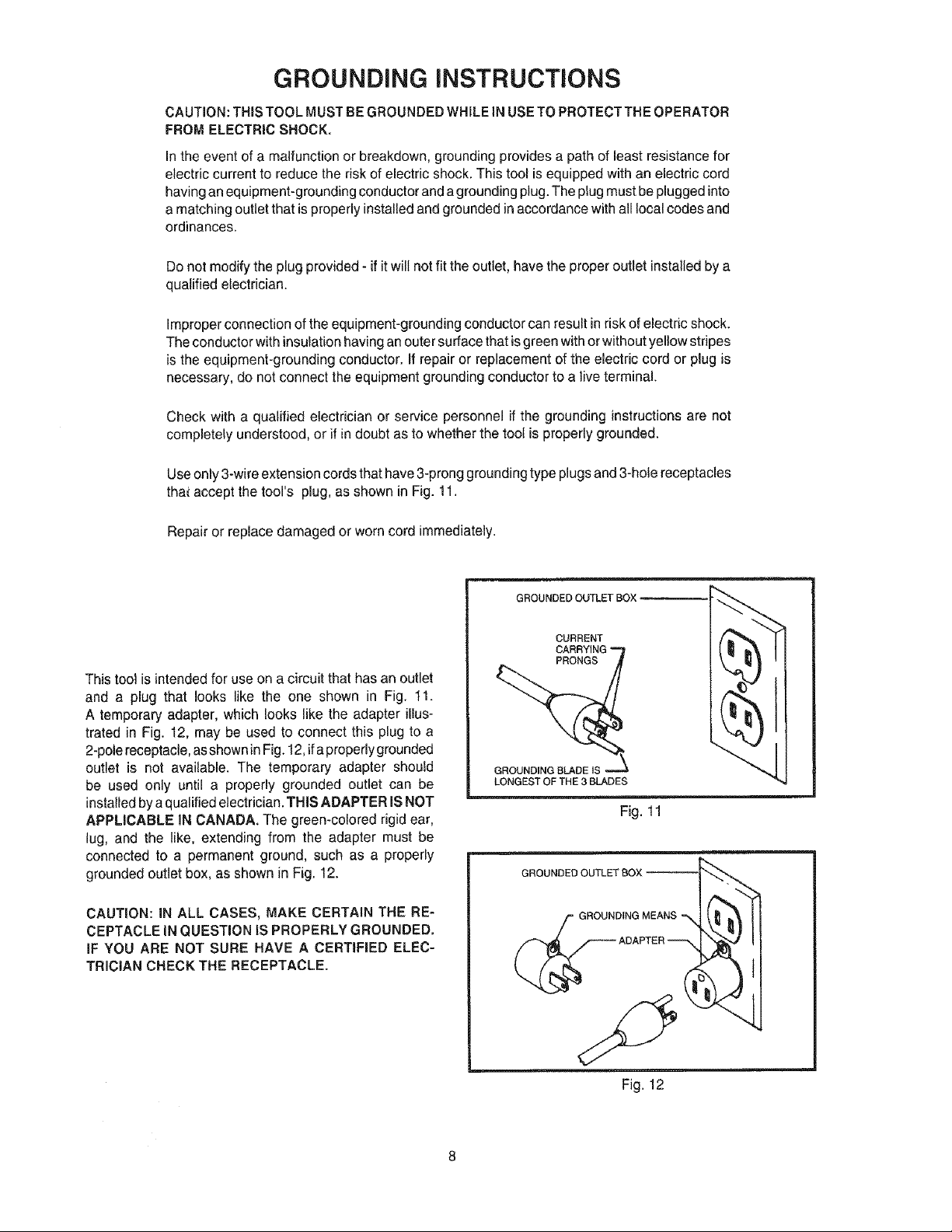
Useonly3-wireextensioncordsthathave3-pronggroundingtype plugsand 3-holereceptacles
thai accept the tool's plug,as shownin Fig. 1t.
Repair orreplace damaged or worncord immediately.
This tool is intended for use on a circuit that has an outlet
and a plug that looks like the one shown in Fig. 11.
A temporary adapter, which looks like the adapter illus-
trated in Fig. 12, may be used to connect this plug to a
2-pole receptacle, asshown in Fig. 12, ifaproperly grounded
outlet is not available. The temporary adapter should
be used only until a properly grounded outlet can be
installed bya qualified electrician. THIS ADAPTER IS NOT
APPLICABLE IN CANADA. The green-colored rigid ear,
lug, and the like, extending from the adapter must be
connected to a permanent ground, such as a properly
grounded outlet box, as shown in Fig. 12.
CAUTION: iN ALL CASES, MAKE CERTAIN THE RE-
CEPTACLE iN QUESTION IS PROPERLY GROUNDED.
iF YOU ARE NOT SURE HAVE A CERTIFIED ELEC-
TRICIAN CHECK THE RECEPTACLE.
GROUNDED OUTLETBOX _1
CURRENT
GROUNDING BLADE IS
LONGEST OF THE 3 BLADES
Fig. 11
GROUNDING MEANS
_ADAPTER_
Fig. t2
Page 9

OPERATING CONTROLS AND ADJUSTMENTS
STARTING AND
STOPPING SAW
The switch (A)Fig. 13,is locatedon the front side of the
bandsaw.To turnthe saw"ON" movethe switch (A)to the
up position.To turn thesaw "OFF" move the switch (A)to
the down position.
LOCKING SWITCH iN
THE "OFF" POSiTiON
We suggest that when the saw is not in use, the switch be
locked inthe "OFF" position. This can be done by grasping
the switch toggle (B) Fig. 14, and pulling itout of the switch,
as shown. With the switch toggle (B) removed, the switch
will not operate. However, should the switch toggle be
removed while the machine is running, the switch can be
turned "OFF" once, but cannot be restarted without
inserting the switch toggle (B).
OPENING AND CLOSING
A'
Fig, 13
Fig. 14
HINGED DOOR
For the purpose of making adjustments such as changing
the blade, tracking the blade, blade guide adjustments,
etc., the hinged door (A) Fig. 15, must be swung open as
follows:
1. CAUTION: NEVER OPEN THE HINGED DOOR
WHEN THE MACHING IS RUNNING.
2. Lift up the two latch levers (B) Fig. 15, and open
door (A).
3. The hinged door (A) is shown in the open position in
Fig. 16,
4. To close and fasten the door (A) Fig. 16,make sure the
expansion latches (C) are inserted into the two bracket
holes (D) and move the latch levers (B) to the down "locked"
position.
Fig, 15
Fig. t6
Page 10
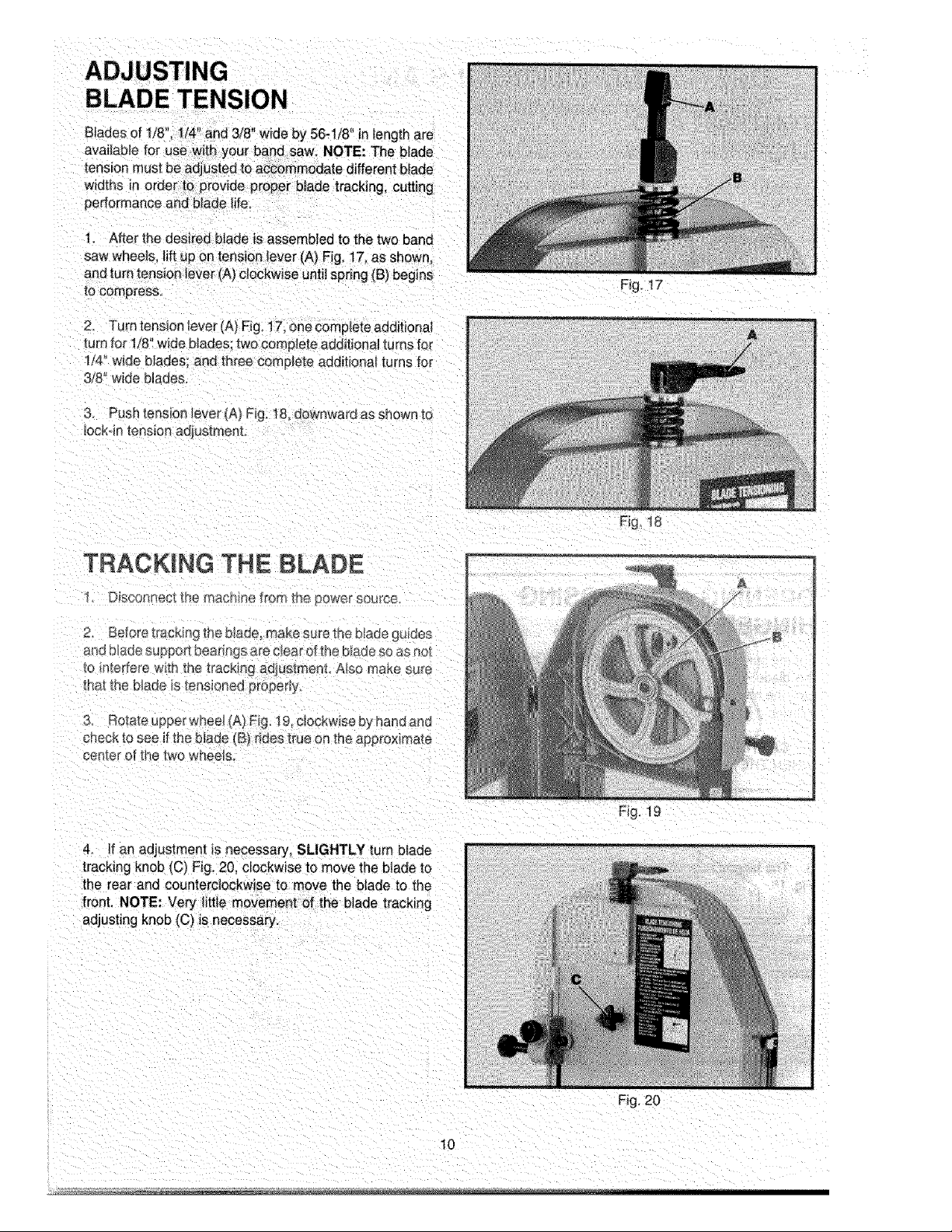
BLADE TENSION
Blades of 1/8" 1/4 and 3/8 wide by 56-1/8" n length are
widths in order to provide proper blade tracking, cutting
performance and blade life,
I, After the desired blade is assembled to the two band
saw wheets, lift eden tension lever (A) Fig. 17 as shown.
and turn tension lever (A)clockwise until spring (t3) eegins
to compress.
2. Turn tensio_ lever (A} Fig, 17, one complete additional
turn for 1/8" wide blades; two complete additional turns for
1/4" w_de blades: andthree complete additional turns for
3/8" wide blades
3, P.sn tension lever (A) Fig. 18, downward as shown to
lockqn tension adjustmem
Fig, 17
Fig 18
TRACKING THE BLADE
I. D_sconnect the machine _o _ _ne }ower source
2. before _racmno the b ade0 make sure the _ aoe gu_ees
and blade s_Ippo_tbesr_ngs are c_earof _he [_aae so as ec [
suFe
center ot the two wneels,
4_ If an adjustment _snecessary, SLIGHTLY turn blade
tracking knob (C) Fig. 20, clockwise to move the blade to
the rear and counterclockwise to move the blade to the
front. NOTE: Very little movement of the blade tracking
adjusting knob (C) is necessary.
FLq. 1
10
Fig, 20
Page 11

Fig__P
ADJUSTING UPPER BLADE GUIDES
iMPORTANT: BOTH THE UPPER AND LOWER BLADE GUIDES MUST BE PROPERLY
ADJUSTED TO PREVENT THE BLADE FROM TWISTING DURING OPERATION.
1. D_sconnec__he machine from me pewer source.
2_ NOTE: Upper biade gJara (B) Fig. 22, _sShOWnremoved for clarity.
3, Loosen the two screws (C) Fig. 22, and adjust the blade guides (D) as close as possible to the
sides of the saw blade, being carefu} not 1o pinch the blade Then tighten the two screws (C),
4, Loosen screw (E) Fig. 22 and move the guide bracket (F) in or out unti! the front edge r_fthe
guides tD_ is just behind the gulJets of the t_lade teeth Then t ghten screw (E)
ADJUSTING°p soppo,b aringUPPER(G>Fig.BLADEpreventsSUPPORTsawbei gBEARING
The r blade 22, the blade from pushed back too
far when cuffing. The support bearing (G_should beadiusted appro×imately 1/;32_'behind the rear
eage of the blade, as follows:
1. Loosen screw _H_Fig 22. and slide support bearing (G] in orout until it is approximately 1/32'
eenmd the rear edge of the saw blade. Then tighten screw (HL
11
Page 12

ADJUSTING LOWER
BLADE GUIDES AND
GUIDE BRACKET
1. DISCONNECT THE MACHINE FROM THE POWER
SOURCE.
(FOR 1/4" AND 3/8" WiDE BLADES ONLY)
2. Loosen the two screws (A) Fig. 23, and adjust the blade
guides, one of which is shown at (B), as close as possible
to the sides of the saw blade, being careful not to pinch the
blade. Then tighten the two screws (A).
3. Loosen two screws (C) Fig. 23, and move the complete
blade guide bracket (D) in or out until the front edge of the
guides (B) is just behind the "gullets" of the blade teeth.
Then tighten the two screws (C).
Fig. 23
(FOR 1/8" WiDE BLADES ONLY)
4. Loosen two blade guide screws (A) Fig. 23.
5. Loosen two screws (C) Fig. 23, and tilt the entire blade
guide bracket (E) Fig. 24, forward as shown until blade
support bearing (F) is approximately 1/32" behind rear
edge of saw blade (G). Tighten two screws (C) Fig. 24.
6. Adjust the blade guides, one of which isshown at (B)
Fig. 23, as close as possible to the sides of the saw blade,
being careful not to pinch the blade. Tighten two blade
guide screws (A) Fig. 23.
ACCESSORY RiP FENCE
OPERATION AND
ADJUSTMENTS
The accessory rip fence (A) Fig. 25, can be moved along
the table surface by liftinglock lever (B) and sliding the rip
fence (A) to the desired location on the table. Push down on
lever (B) to firmly lock rip fence in position on the table.
NOTE: A handy English/Metric scale (C) indicates the
distance the fence is positioned from the saw blade.
For accurate work, the rip fence (A) Fig.25, must beparallel
tothe miter gage slot (D). Move the rip fence (A) to the edge
of the miter gage slot and check the alignment. If an
adjustment is necessary:
i jG
1
C
'Ul
Fig. 24
1. Loosen two screws (E) Fig. 25, and raise locking
lever (B).
2. While holding ripfence bracket (F) Fig. 25,firmly, move
the far end of the fence (A) until it is parallel with the miter
gage slot (D).
3. Tighten two screws (E) Fig. 25, and push down on
locking lever (B).
4. Clamping action on the rip fence (A) Fig. 25, can be
tightened or loosened by liftinglocking lever (B) and rotat-
ing lever (B) clockwise or counterclockwise as necessary.
Fig. 25
12
Page 13
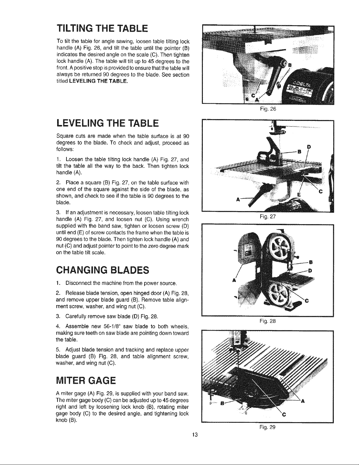
TiLTiNG THE TABLE
To tilt the table for angle sawing, loosen table tilting lock
handle (A) Fig. 26, and tilt the table until the pointer (B)
indicates the desired angle on the scale (C). Then tighten
tock handle (A). The table will tilt up to 45 degrees to the
front. A positive stop is provided to ensure that the table will
always be returned 90 degrees to the blade. See section
titled LEVELING THE TABLE.
LEVELING THE TABLE
Square cuts are made when the table surface is at 90
degrees to the blade. To check and adjust, proceed as
follows:
1. Loosen the table tilting lock handle (A) Fig. 27, and
tilt the table all the way to the back. Then tighten lock
handle (A).
2. Place a square (B) Fig. 27, on the table surface with
one end of the square against the side of the blade, as
shown, and check to see if the table is 90 degrees to the
blade.
3. if an adjustment is necessary, loosen table tilting lock
handle (A) Fig. 27, and loosen nut (C). Using wrench
supplied with the band saw, tighten or loosen screw (D)
until end (E) of screw contacts the frame when the table is
90 degrees to the blade. Then tighten lock handle (A) and
nut (C) and adjust pointer to point to the zero degree mark
on the table tilt scale.
CHANGING BLADES
1. Disconnect the machine from the power source.
2. Release blade tension, open hinged door (A) Fig. 28,
and remove upper blade guard (B). Remove table align-
ment screw, washer, and wing nut (C).
3. Carefully remove saw blade (D) Fig. 28.
4. Assemble new 56-1/8" saw blade to both wheels,
making sure teeth on saw blade are pointing down toward
the table.
5. Adjust blade tension and tracking and replace upper
blade guard (B) Fig. 28, and table alignment screw,
washer, andwing nut (C).
MITER GAGE
Fig. 27
Fig. 28
A miter gage (A) Fig. 29, is supplied with your band saw.
The miter gage body (C) can be adjusted up to 45 degrees
right and left by loosening lock knob (B), rotating miter
gage body (C) to the desired angle, and tightening lock
knob (B).
Fig. 29
13
Page 14

Fig.30
Fig. 31
DUST CHUTE
A dust chute (A) Fig, 30, is supplied with your bench band
saw and is equipped with a 1-1/2" I.D. opening that can
easily be connected to a dust collection system.
BLADE AND
WHEEL BRUSH
A blade and wheel brush (A) Fig. 32, is supplied inside
the band saw frame to prevent sawdust and chips from
traveling with the blade. The brush can be adjusted by
loosening screw (B) and adjusting holder (A) closer to the
wheel. Then tighten screw (B).
0
0
o
0
0
0
Delta Building Trades and Home Shop Machinery
0
0
0
Delta will repair or replace, at its expense and at its option, any Delta machine,
machine part, or machine accessory which in normal use has proven to be defective
0
in workmanship or material, provided that the customer returns the product
0
prepaid to a Delta factory service center or authorized service station with proof of
0
purchase of the product within two years and provides Delta with reasonable
0
0
opportunity to verify the alleged defect by inspection. Delta may require that
electric motors be returned prepaid to a motor manufacturer's authorized station
0
for inspection and repair or replacement. Delta will not be responsible for any
0
0
asserted defect which has resulted from normal wear, misuse, abuse or repair or
0
alteration made or specifically authorized by anyone other than an authorized Delta
0
service facility or representative. Under no circumstances will Delta be liable for
0
incidental or consequential damages resulting from defective products. This
0
warranty is Delia's sole warranty and sets forth the customer's exclusive remedy,
with respect to defective products; all other warranties, express or implied, whether
o
o
of merchantability, fitness for purpose, or otherwise, are expressly disclaimed by
o
Delta.
&
AAD m LTA
Two Year Limited Warranty
WRENCH HOLDER
A wrench holder (A) Fig. 31, is supplied on the back of the
saw frame to hold the adjusting wrench (B). The adjusting
wrench (B) is used for most of the adjustments on the band
saw, and the holder (A) enables you to store the wrench
with the saw and prevent the wrench from being lost.
Fig. 32
0
o
0
0
o
0
o
0
o
0
0
0
0
0
0
0
14
Printed in U.S.A.
Page 15

PORTER-CABLE • DELTA SERVICE CENTERS
(CENTROS DE SERVICIO DE PORTER-CABLE o DELTA)
Parts andRepair Servicefor Porter-Cable• DeltaMachineryare Availableat These Locatiens
(Obtenga RefacciondeParteso Servicio para su Herramientaenlos Siguientes Centrosde Porter-Cable• Delta)
ARIZONA
Temps 85282 (Phoenix)
2400 West Southern Avenue
Suite 105
Phone: (602) 437-1200
Fax: (602)437-2200
CALiFORNiA
Ontario 91761 (Los Angeles)
3949A East Guasti Road
Phone: (909) 390-5555
Fax: (909)390-5554
San Leandro 94577 (Oakland)
3039 Teagarden Street
Phone: (510) 357-9762
Fax: (510)357-7939
COLORADO
Arvada 80003 (Denver)
8175 Sheridan Blvd., Unit S
Phone: (303) 487-1809
Fax: (303)487-1868
FLORIDA
Davie 33314 (Miami)
4343 South State Rd. 7 (441)
Unit #107
Phone: (954) 321-6635
Fax: (954)321-6638
Tampa 33609
4538 W. Kennedy Boulevard
Phone: (813) 877-9585
Fax: (813)289-7948
GEORGIA
Forest Park 30297 (Atlanta)
5442 Frontage Road,
Suite 112
Phone: (404) 608-0006
Fax: (404)608-1123
iLLINOIS
Addison 60101 (Chicago)
400 South Rohlwing Rd.
Phone: (630)424-8805
Fax: (630)424-8895
Woodridge 60517 (Chicago)
2033 West 75th Street
Phone: (630) 910-9200
Fax: (630)910-0360
MARYLAND
Elkridge 21075 (Baltimore)
7397-102 Washington Blvd.
Phone: (410) 799-9394
Fax: (410)799-9398
MASSACHUSETTS
Braintree 02185 (Boston)
719 Granite Street
Phone: (781) 848-9810
Fax: (781)848-6759
Franklin 02038 (Boston)
Franklin Industrial Park
101E Constitution Blvd.
Phone: (508) 520-8802
Fax: (508)528-8089
MiCHiGAN
Madison Heights 48071 (Detroit)
30475 Stephenson Highway
Phone: (248) 597-5000
Fax: (248)597-5004
MINNESOTA
Minneapolis 55429
5522 Lakeland Avenue North
Phone: (763) 561-9080
Fax: (763)561-0653
MISSOURi
North Kansas City 64116
1141 Swift Avenue
Phone: (816) 221-2070
Fax: (816)221-2897
St. Louis 63119
7574 Watson Road
Phone: (314) 968-8950
Fax: (314)968-2790
NEW YORK
Flushing 11365-1595 (N.Y.C.)
175-25 Horace Harding Expwy.
Phone: (718) 225-2040
Fax: (718)423-9619
NORTH CAROLINA
Charlotte 28270
9129 Monroe Road, Suite 115
Phone: (704) 841-1176
Fax: (704)708-4625
OHiO
Columbus 43214
4560 Indianola Avenue
Phone: (614) 263-0929
Fax: (614)263-1238
Authorized Service Stations are located in many large cities. Telephone 800-438=2486or 731=541-6042 for assistance locating one.
Parts andaccessories for Porter-Cable"Delta products should be obtained by contacting any Porter-Cable"Delta Distributor,Authorized
Service Center,or Porter-Cable'Delta Factory Service Center.Ifyou do not haveaccess to any of these, call 800-223-7278 and you will
be directed to thenearest Porter-Cable"DeltaFactory ServiceCenter. Las Estacionesde Servicio Autorizadas estan ubicadas en muchas
grandes ciudades. Llame al800-438=2486 6 a1731=541-6042para obtener asistencia a fin de Iocalizar una.Las piezasy los accesorios
para los productos Porter-Cable'Delta deben obtenerse poniendose en contacto con cualquier distribuidor Porter-Cable'Delta, Centro
de Servicio Autorizado o Centro de Servicio de Fabrica Porter-Cable.Delta. Si no tiene acceso a ninguna de estas opciones, Ilame al
800-223-7278 y le dirigiran al Centro de Servicio de Fabrica Porter-Cable'Delta mas cercano.
Cleveland 44125
8001 Sweet Valley Drive
Unit #19
Phone: (216) 447-9030
Fax: (216)447-3097
OREGON
Portland 97230
4916 NE 122 ndAve.
Phone: (503) 252-0107
Fax: (503)252-2123
PENNSYLVANIA
Willow Grove 19090
520 North York Road
Phone: (215) 658-1430
Fax: (215)658-1433
TEXAS
Carrollton 75006 (Dallas)
1300 Interstate 35 N, Suite 112
Phone: (972) 446-2996
Fax: (972)446-8157
Houston 77038
4321 Sam Houston Parkway,
West
Suite 180
Phone: (281) 260-8887
Fax: (281)260-9989
WASHINGTON
Auburn 98001(Seattle)
3320 West Valley HWY, North
Building D, Suite 111
Phone: (253) 333-8353
Fax: (253)333-9613
CANADIAN PORTER=CABLE • DELTA SERVICE CENTERS
ALBERTA MANITOBA QUEBEC
Bay 6, 2520-23rd St. N.E. 1699 Dublin Avenue 1515 ave.
Calgary, Alberta Winnipeg, Manitoba St-Jean Baptiste, Suite 160
T2E 8L2 R3H 0H2 Quebec, Quebec
Phone: (403) 735-6166 Phone: (204)633-9259 G2E 5E2
Fax: (403)735-6144 Fax: (204)632-1976 Phone: (418)877-7112
ONTARIO Fax: (418)877-7123
BRiTiSH COLUMBIA 505 Southgate Drive 1447, Begin
8520 Baxter Place Guelph, Ontario St-Laurent, (Montreal),
Burnaby, B.C. N1H 6M7 Quebec
V5A 4T8 Phone: (519) 767-4132 H4R 1V8
Phone: (604) 420-0102 Fax: (519) 767-4131 Phone: (514)336-8772
Fax: _420-3522 Fax: 51(._]_336-3505
The following are trademarks of PORTER-CABLE.DELTA(Las siguientesson mamas registradas de PORTER-CABLEB.A.):Auto-Set®,
BAMMER®,B.O.S.S.®,Builder's Saw%Contractor's Saw®,Contractor's Saw IITM, Delta®,DELTACRAFT®,DELTAGRAMTM, Delta Series
2000TM, DURATRONICTM, Emc2tM, FLEX®,Flying Chips TM, FRAME SAW®,Homecraft ®,INNOVATION THAT WORKS®,Jet-Lock ®,
JETSTREAM®,'kickstand ®,LASERLOC®,MICRO-SET®,Micro-Set ®,MIDI LATHE®,MORTENTM, NETWORKTM, OMNIJIG®,POCKET
cUTrER®,PORTA-BAND®,PORTA-PLANE®,PORTER-CABLE®&(design),PORTER-CABLE®PROFESSIONALPOWERTOOLS,Posi-Matic®,
Q-3®&(design),QUICKSAND®&(design),QUICKSETTM, QUICKSETII®,QUICKSETPLUSTM, RIPTIDEZN&(design),SAFE GUARDII®,SAFE-
LOC®, Sanding Center®,SANDTRAP'_&(design),SAW BOSS®,SawbuckTM, Sidekick®,SPEED-BLOC®,SPEEDMATIC®,SPEEDTRONIC®,
STAIREASE®,The American Woodshop®&(design),The Lumber Company_&(design),THE PROFESSIONALEDGE®,THE PROFESSIONAL
SELECT®,THIN-LINF M,TIGER®,TIGER CUB®,TIGER SAW®,TORQBUSTER®,TORQ-BUSTER ®,TRU-MATCH TM, TWlN-LITE ®,
UNIGUARD®,Unifence®,UNIFEEDERTM , Unihead®,UniplaneTM , Unirip®,Unisaw%Univise®,Versa-Feeder®,VERSA-PLANE®, WHISPER
SERIES®,WOODWORKER'SCHOICF M.
Trademarksnoted with TMand ® are registered in the United States Patent and TrademarkOffice and may also be registered in other
countries. LasMamas Registradascon e]signo de TMy ® son registradas pot la Oficina deRegistrosy Patentesde los E-stadosUnidos y
tambien puedenestar reglstradasen otros paises. Printedin U.S.A.
 Loading...