

Page 1

12-inch Sliding Compound Miter Saw
Scie à onglets composée coulissante 12 pouces
Sierra de inglete compuesta deslizante de 12 pulgadas
Français (25)
Español (49)
www.DeltaMachinery.com
Instruction Manual
Manual d’utilisation
Manual de instrucciones
To reduce the risk of serious injury, thoroughly read and comply with all warnings and instructions in this manual and on product
KEEP THIS MANUAL NEAR YOUR PRODUCT FOR EASY REFERENCE AND TO INSTRUCT OTHERS
26-2250
Page 2

TABLE OF CONTENTS
Important Safety Instructions .................................. 2
Safety Logos .................................................................. 2
General Power Tool Safety Rules ............................. 3
Proposition 65 Warning .............................................. 4
Miter Saw Safety Rules ............................................... 4
Power Connections ...................................................... 5
Double Insulation .......................................................... 5
Electrical Connection ..................................................... 6
Polarized Plugs .............................................................. 6
Extension Cords ............................................................ 6
Features ......................................................................... 6
Product Specications.................................................... 6
Know Your Compound Miter Saw ....................................8
Unpacking ...................................................................... 8
Removing Contents From Packing ..................................8
Packaged Contents List .................................................. 9
Mounting And Transportation ................................... 9
Preparations For Transportation...................................... 9
Mounting Saw To Stable Surface .................................. 10
Assembly ...................................................................... 10
Tools Needed .............................................................. 10
Work Clamp ................................................................ 10
Dust Bag .................................................................... 11
Install/Remove/Replace The Blade ............................... 12
Operation ..................................................................... 13
Cutting Warped Material .............................................. 13
Clamping Wide Workpieces .......................................... 14
Supporting Long Workpieces ........................................ 14
Power Switch Lock ...................................................... 14
Non-Sliding Cuts ......................................................... 15
For Miter Cuts ............................................................. 15
For Bevel Cuts ............................................................ 16
For Compound Miter Cuts ............................................ 16
Slide Cuts ................................................................... 17
Tips For Cutting Crown Molding.................................... 17
Auxiliary Fence ........................................................... 18
Increase Cut Capacity .................................................. 19
Adjustments ................................................................ 20
Align The Blade To Table ............................................. 20
Align The Blade To Fence ............................................. 20
Depth Stop ................................................................. 21
Fence Extension .......................................................... 21
Slide Resistance .......................................................... 22
Throat Plate................................................................ 22
Maintenance ................................................................ 23
Keep Machine Clean .................................................... 23
General Maintenance ................................................... 23
Brush Replacement ..................................................... 23
Lubrication ................................................................. 23
Trouble Shooting ........................................................ 23
Failure To Start ........................................................... 23
Accessories .................................................................. 24
Parts, Services Or Warranty Assistance ................ 24
Replacement Parts ...................................................... 24
Free warning Label Replacement .................................. 24
Service and Repairs ..................................................... 24
French ........................................................................... 25
Spanish ......................................................................... 49
NOTE: The manual cover illustrates the current production model. All other illustrations contained in the manual are representative
only and may not be exact depictions of the actual labeling or accessories included. They are intended for illustrative purposes only.
IMPORTANT SAFETY INSTRUCTIONS
CAREFULLY READ AND FOLLOW ALL WARNINGS AND INSTRUCTIONS ON YOUR PRODUCT
AND IN THIS MANUAL. SAVE THIS MANUAL. MAKE SURE ALL USERS ARE FAMILIAR WITH ITS
WARNINGS AND INSTRUCTIONS WHEN USING THE TOOL. Improper operation, maintenance or modication of
tools or equipment could result in serious injury and/or property damage.
SAFETY LOGOS
This manual contains information that is important for you to know and understand. This information relates to protecting YOUR
SAFETY and PREVENTING EQUIPMENT PROBLEMS. To help you recognize this information, we use the symbols below. Please read
the manual and pay attention to these sections.
Indicates an imminently hazardous situation which, if not avoided, will result in death or serious injury.
Indicates a potentially hazardous situation which, if not avoided, could result in death or serious injury.
Indicates a potentially hazardous situation which, if not avoided, may result in minor or moderate injury.
Used without the safety alert symbol indicates potentially hazardous situation which, if not avoided, may result in
property damage.
Additional information regarding the safe and proper operation of this tool is available from the following sources:
• Power Tool Institute, 1300 Sumner Avenue, Cleveland, OH 44115-2851 or on-line at www.powertoolinstitute.com
• National Safety Council, 1121 Spring Lake Drive, Itasca, IL 60143-3201
• American National Standards Institute, 25 West 43rd Street, 4 oor, New York, NY 10036 www.ansi.org - ANSI 01.1 Safety
Requirements for Woodworking Machines
• U.S. Department of Labor regulations www.osha.gov
2 3
Page 3

GENERAL POWER TOOL SAFETY RULES
Read all safety warnings, instructions, illustrations and specications provided with this power tool.
Failure to follow all instructions listed below may result in electric shock, re and/or serious injury.
Save all warnings and instructions for future reference.
The term “power tool” in the warnings refers to your mains-operated (corded) power tool or BATTERY-operated (cordless) power
tool.
1. Work area safety
a. Keep work area clean and well lit. Cluttered or dark areas invite accidents
b. Do not operate power tools in explosive atmospheres, such as in the presence of ammable liquids,
gases or dust. Power tools create sparks which may ignite the dust or fumes.
c. Keep children and bystanders away while operating a power tool. Distractions can cause you to lose control.
2. Electrical safety
a. Power tool plugs must match the outlet. Never modify the plug in any way. Do not use any adapter with
earthed (grounded) power tools. Unmodied plugs and matching outlets will reduce risk of electric shock
b. Avoid body contact with earthed or grounded surfaces, such as pipes, radiators, ranges and
refrigerators. There is an increased risk of electric shock if your body is earthed or grounded.
c. Do not expose power tools to rain or wet conditions. Water entering a power tool will increase the risk of
electric shock.
d. Do not abuse the cord. Never use the cord for carrying, pulling or unplugging the power tool. Keep cord
away from heat oil, sharp edges or moving parts. Damaged or entangled cords increase the risk of electric
shock.
e. When operating a power tool outdoors, use an extension cord suitable for outdoor use. Use of a cord
suitable for outdoor use reduces the risk of electric shock.
f. If operating a power tool in a damp location is unavoidable, use a ground fault circuit interrupter (GFCI)
protected supply. Use of an GFCI reduces the risk of electric shock.
3. Personal safety
a. Stay alert, watch what you are doing and use common sense when operating a power tool. Do not use
a power tool while you are tired or under the inuence of drugs, alcohol or medication. A moment of
inattention while operating power tools may result in serious personal injury.
b. Use personal protective equipment. Always wear eye protection. Protective equipment such as dust mask,
non-skid safety shoes, hard hat, or hearing protection used for appropriate conditions will reduce personal injuries.
c. Prevent unintentional starting. Ensure the switch is in the off-position before connection to power
source, picking up, or carrying the tool. Carrying power tools with your nger on the switch or energising power
tools that have the switch on invites accidents.
d. Remove any adjusting key or wrench before turning the power tool on. A wrench or a key left attached to a
rotating part of the power tool may result in personal injury.
e. Do not overreach. Keep proper footing and balance at all times. This enables better control of the power tool
in unexpected situations
f. Dress properly. Do not wear loose clothing or jewelery. Keep your hair, clothing and gloves away from
moving parts. Loose clothes, jewelery or long hair can be caught in moving parts.
g. If devices are provided for the connection of dust extraction and collection facilities, ensure these are
connected and properly used. Use of dust collection can reduce dust-related hazards.
h. Do not let familiarity gained from frequent use of tools allow you to become complacent and ignore tool
safety principles. A careless action can cause severe injury within a fraction of a second.
i. Never stand on tool. Serious injury could occur if the tool is tipped or if the cutting tool is unintentionally contacted.
4. Power tool use and care
a. Do not force the power tool. Use the correct power tool for you application. The correct power tool will do
the job better and safer at the rate for which it was designed.
b. Do not use the power tool if the switch does not turn it on and off. Any power tool that cannot be controlled
with the switch is dangerous and must be repaired.
c. Disconnect the plug from the power source before making any adjustments, changing accessories, or
storing power tool. Such preventive safety measures reduce the risk of starting the power tool accidentally.
d. Store idle power tools out of the reach of children and do not allow persons unfamiliar with the power
tool or these instructions to operate the power tool. Power tools are dangerous in the hands of untrained users.
e. Maintain power tools and accessories. Check for misalignment or binding of moving parts , breakage of
parts and any other condition that may affect the power tool’s operation. If damaged, have the power
tool repaired before use. Many accidents are caused by poorly maintained power tools.
3
Page 4

f. Keep cutting tools sharp and clean. Properly maintained cutting tools with sharp cutting edges are less likely to
bind and are easier to control.
g. Use the power tool, accessories and tools bits etc. In accordance with these instructions, taking into
account the working conditions and the work to be performed. Use of the power tool for operations different
from those intended could result in a hazardous situation.
h. Keep Handels and grasping surfaces dry, clean and free from oil and grease. Slippery handles and grasping
surfaces do not allow for safe handling and control of the tool in unexpected situations.
5. Service
a. Have your power tool serviced by a qualied repair person using only identical replacement parts. This
will ensure that the safety of the power tool is maintained.
PROPOSITION 65 WARNING:
Some dust created by power sanding, sawing, grinding, drilling, and other construction activities contains
chemicals known to the state of California to cause cancer, birth defects or other reproductive harm. Some examples of these
chemicals are:
• Lead from lead-based paints
• Crystalline silica from bricks and cement and other masonry products
• Arsenic and chromium from chemically-treated lumber
Your risk from these exposures varies, depending on how often you do this type of work. To reduce your exposure to these
chemicals: work in a well-ventilated area and work with approved safety equipment, such as dust masks that are specifically
designed to filter out microscopic particles.
MITER SAW SAFETY RULES
1. Safety instructions for miter saws
a. Miter saw are intended to cut wood or wood-like products, they cannot be used with abrasive cut-off
wheels for cutting ferrous material such as bars, rods, studs, etc. Abrasive dust causes moving parts such as
the lower guard to jam. Sparks from abrasive cutting will burn the lower guard, the kerf insert and other plastic parts.
b. Use clamps to support the workpiece whenever possible. If supporting the workplace by hand, you must
always keep your hand at least 100mm from either side of the saw blade. Do not use this saw to cut
pieces that are too small to be securely clamped or held by hand. If your hand is placed too close to the saw
blade, there is an increased risk of injury from blade contact.
c. The workplace must be stationary and clamped or held against both the fence and the table. Do not feed
the workplace into the blade or cut “freehand” in any way. Unrestrained or moving workplace could be thrown
at high speeds, causing injury.
d. Push the saw through the workpiece. Do not pull the saw through the workpiece. to make a cut, raise
the saw head and pull it out over the workpiece without cutting, start the motor, press the saw head
down and push the saw through the workpiece. Cutting on the pull stroke is likely to cause the saw blade to
climb on top of the workpiece and violently throw the blade assembly towards the operator.
e. Never cross your hand over the intended line of cutting either in front or behind the saw blade.
Supporting the workpiece “cross handed” i.e. holding the workpiece to the right of the saw blade with your left hand or
vice versa is very dangerous.
f. Do not reach behind the fence with either hand closer than 100mm from either side of the saw blade, to
remove wood scraps, or for any other reason while the blade is spinning. The proximity of the spinning saw
blade to your hand may not be obvious and you may be seriously injured.
g. Inspect your workpiece before cutting. If the workpiece is bowed or warped,clamp it with the outside
bowed face toward the fence. Always make certain that there is no gap between the workpiece, fence
and table along the line of the cut. Bent or warped workpieces can twist or shift and may cause binding on the
spinning saw blade while cutting. There should be no nails or foreign objects in the workpiece.
h. Do not use the saw until the table is clear of all tools, wood scraps, etc., except for the workpiece. Small
debris or loose pieces of wood or other objects that contact the revolving blade can be thrown with high speed.
i. Cut only one workpiece at a time. Stacked multiple workpieces cannot be adequately clamped or braced and may
bind on the blade or shift during cutting.
j. Ensure the miter saw is mounted or placed on a level, rm work surface before use. A level and rm work
surface reduces the risk of the miter saw becoming unstable.
4 5
Page 5

MITER SAW SAFETY RULES
k. Plan your work. Every time you change the bevel or miter angle setting, make sure the adjustable fence
is set correctly to support the workpiece and will not interface with the blade or the guarding system.
Without turning the tool “ON” and with no workpiece on the table, move the saw blade through a complete simulated
cut to assure there will be no interference or danger of cutting the fence.
l. Provide adequate support such as table extensions, saw horses, etc. for a workpiece that is wider or
longer than the table top. Workpieces longer or wider than the miter saw table can if not securely supported. If the cut-off
piece or workpiece tips, it can lift the lower guard or be thrown by the spinning blade.
m. Do not use another person as a substitute for a table extension or as additional support. Unstable support
for the workpiece can cause the blade to bind or the workpiece to shift during the cutting operation pulling you and
the helper into the spinning blade.
n. The cut-off piece must not be jammed or pressed by any means against the spinning saw blade. If
conned, i.e. using length stops, the cut-off piece could get wedged the blade and thrown violently.
o. Always use a clamp or a xture designed to properly support round material such as rods or tubing. Rods
have a tendency to roll while being cut, causing the blade to “bite” and pull the work with your hand into the blade.
p. Let the blade reach full speed before contacting the workpiece. This will reduce the risk of the workpiece
being thrown
q. If the workpiece or blade becomes jammed,turn the miter saw off. Wait for all moving parts to stop
and disconnect the plug from the power source and/or remove the battery pack. Then work to free the
jammed material. Continued sawing with a jammed workpiece could cause loss of control or damage ti the miter
saw.
r. After nishing the cut, release switch, hold the saw down and wait for the blade to stop before removing
the cut-off piece. Reaching with your hand near the coasting blade is dangerous.
s. Hold the handle, rmly when making an incomplete cut or when releasing the switch before the saw
head is completely in the position. The breaking action of the saw may cause the saw to be suddenly pulled
downward, causing a risk of injury.
t. Saw Head lock pin is for storage and transport only. This saw should never be locked in the down position while
making cuts.
u. Do not operate saw without guards in place.
SAVE THESE INSTRUCTIONS.
Refer to them often and use them to instruct others.
If tool is loaned to someone, also loan them these instructions.
POWER CONNECTIONS
A separate electrical circuit should be used for your machines. This circuit should not be less than #12 wire. Before connecting
the machine to the power line make sure the switch(s) is in the “OFF” position and be sure that the electric current is of the same
characteristics as indicated on the wmachine. All line connections should make good contact. Running on low voltage will damage
the machine.
DO NOT EXPOSE THE MACHINE TO RAIN OR OPERATE THE MACHINE IN DAMP LOCATIONS.
Your machine is wired for 120 volts, 60 HZ alternating current. Before connecting the machine to the power source, make sure the
switch is in the “OFF” position.
DOUBLE INSULATION
This machine is double insulated. Double insulation is a concept in safety in electric power tools, which eliminates the need for
the usual three-wire grounded power cord. All exposed metal parts are isolated from the internal metal motor components with
protecting insulation. Double insulated tools do not need to be grounded.
The double insulated system is designed to protect the user from shock resulting from a break in the tool’s
internal insulation. However, it is important to observe normal safety precautions to avoid electrical shock
NOTE: Servicing of a tool with double insulation requires extreme care and knowledge of the system and should be performed by
a qualified service technician. For service, we suggest you return the tool to the nearest authorized service center for repair. Always
use identical replacement parts when servicing.
5
Page 6

POWER CONNECTIONS
ELECTRICAL CONNECTION
This tool has a precision-built electric motor. It should be connected to a POWER SUPPLY THAT IS 120 VOLTS, 60 HZ, AC ONLY
(NORMAL HOUSEHOLD CURRENT). Do not operate this tool on direct current (DC). A substantial voltage drop will cause a loss of
power and the motor will overheat. If the tool does not operate when plugged into an outlet, double-check the power supply.
POLARIZED PLUGS
To reduce the risk of electric shock, this equipment has a polarized plug (one blade is wider than the other). This plug will fit in a
polarized outlet only one way. If the plug does not fully fit in the outlet reverse the plug. If it still does not fit, contact a qualified
electrician to install the proper outlet. Do not change the plug in any way.
EXTENSION CORDS
When using a power tool at a considerable distance from a power source, be sure to use an extension cord that has the capacity to
handle the current the tool will draw. An undersized cord will cause a drop in line voltage, resulting in overheating and loss of power.
Use the chart to determine the minimum wire size required in an extension cord. Only round jacketed cords listed by Underwriter’s
Laboratories (UL) should be used.
NOTE: Before using any extension cord, inspect it for loose or
exposed wires and cut or worn insulation.
** Ampere rating (on total data label)
Keep the extension cord clear of the work
area. Position the cord so that it will not get caught on lumber,
tools or other obstructions while you are working with a power
tool. Failure to do so can result in serious personal injury.
Check extension cords before each use. If damaged replace
immediately. Never use tool with a damaged cord, since
touching the damaged area could cause electrical shock
resulting in serious injury.
FEATURES
PRODUCT SPECIFICATIONS
Cutting Capacity
(Maximum nominal lumber
sizes)
Baseboard (Vertical) 6.5”
Crown (Vertically Nested) 7.5”
Net Weight 57 lbs
Input 120 V~, 60hz, 15 Amps
Blade Arbor Hole 1”
Blade Diameter 12”
No Load Speed 4,000 r/min (RPM)
12A- 16A
Cord Length Wire Size
25’ 14 AWG
50’ 12 AWG
** Used on 12 gauge - 20 amp circuit
NOTE: AWG = American Wire Gauge
0° Miter/0° Bevel: 4” x 14” (2 x18”) Extended Capacity
45° Miter/ 0° Bevel: 4” x 10”
0° Miter/45° Bevel: 2” x 14”
45° Miter/45° Bevel: 2” x 10”
6 7
Page 7
FEATURESFEATURES
15
x2
12
11
10
9
8
7
13
14
16
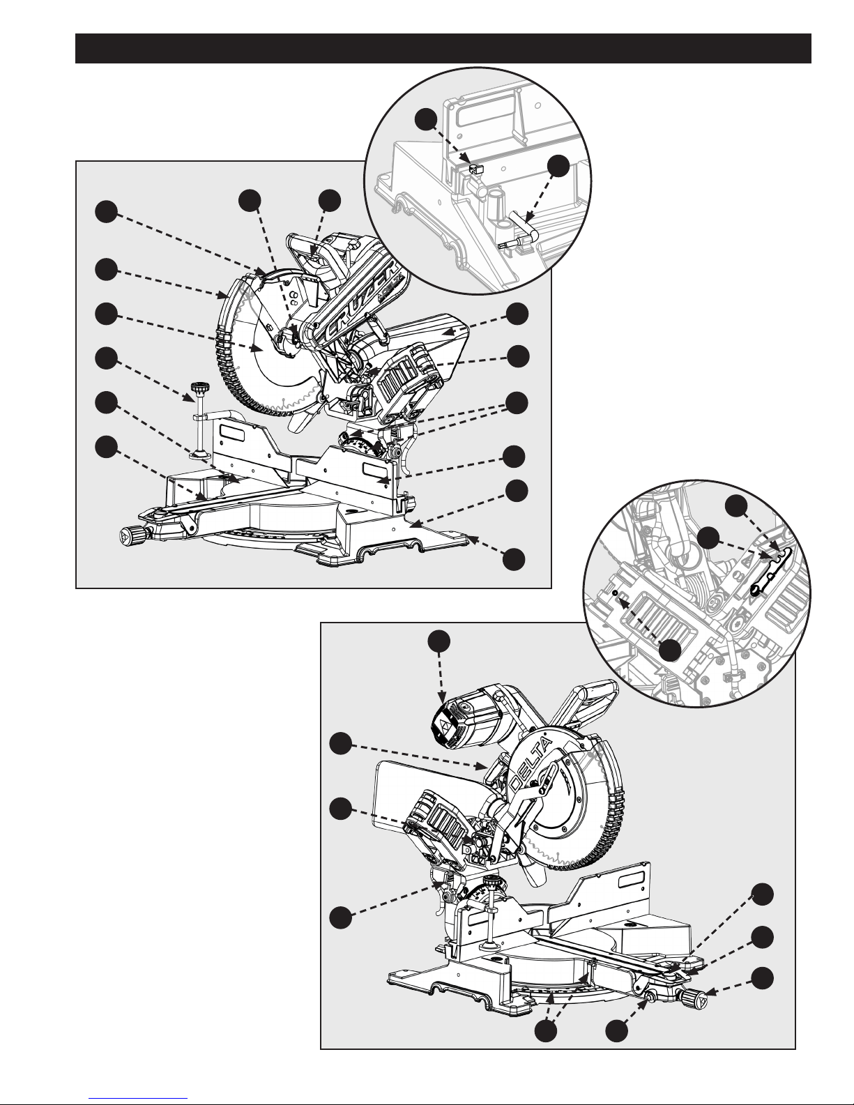
1. Dust Bag
2. Depth Stop
3. Bevel Scale and Pointer (x2)
4. Sliding Fence
5. Base
6. Mounting Holes (x4)
7. Throat Plate
1
8. Work Table
9. Clamp
10. Blade
2
11. Lower Guard
12. Upper Guard
3
13. Spindle Lock
14. On/Off Switch and Lockout Hole
15. Back Fence Support
4
16. Torx Wrench
5
28
23
6
x4
17. Miter Detent Lock/Unlock Button
18. Bevel Lock/Unlock Handle
19. Miter Lock Knob
20. Miter Detent Override Button
21. Miter Scale and Pointer
22. Bevel Detent Latch (x2)
23. Slide Lock
24. Head Lock
25. Carrying Handle
26. Brush Cap
27. Glide Adjustment
28. Baseboard Position Lock
29. E-Brake (Not Shown)
Figure 1
25
24
22
x2
26
27
x2
17
18
19
21
Figure 2
20
7
Page 8

FEATURESFEATURES
KNOW YOUR COMPOUND MITER SAW
1. Dust Collection Bag: The dust bag collects and
contains the saw dust during the cutting operations.
2. Depth Stop: The depth stop plate can be used to
make a non-through cut. The depth stop screw allows
the depth of cut to be adjusted.
3. Bevel Scale and Pointer: These indicate the
current blade bevel position and are adjustable; This
allows for ne calibration of the blade alignment.
4. Adjustable Fence: The fence supports the
workpiece when making all cuts. The extension is
adjustable.
5. Base: Supports the tool and features mounting holes.
6. Mounting Holes (x4): Enables you to securely
mount the tool to a stable surface.
7. Throat Plate (Kerf Plate): The kerf plate supports
the workpiece from underneath, on both sides of the
blade, to minimize workpiece tear out
8. Work Table: The die-cast aluminum work table
provides a level and sturdy work surface.
9. Clamp: The vertical work clamp helps to position and
secure the workpiece to the work table. This provides
for safer operation and more accurate cuts.
10. Blade: A 12 inch blade is included with the compound
miter saw.
11. Lower Guard: The lower blade guard is made of
shock-resistant, see-through plastic that provides
protection from the blade.
12. Upper Guard: Cast aluminum protects user from
blade.
13. Spindle Lock: Engage the spindle lock when
changing the blade in order to hold the blade into
position while you loosen the blade bolt.
14. Power Switch and Power Lockout: This
saw is activated by an easy to use, hand operated,
power switch. When not in use the saw should be
disconnected from the power supply and locked using a
padlock inserted through the lockout hole located on the
power switch.
15. Back Fence Support: These provide workpiece
support and additional cut capacity when the sliding
fence is removed.
16. Torx Wrench: This wrench features two Torx head
17. Miter Detent Lock/Unlock Button: This button
18. Bevel Lock/Unlock Handle: This handle locks
19. Miter Lock Knob: This knob locks the blade miter
20. Miter Detent Override Button: This button holds
21. Miter Scale and Pointer: These indicate the
22. Bevel Latch (x2): This latch engages/disengages
23. Slide Lock: This allows the saw head to be locked
24. Head Lock: This allows the saw head to be locked
25. Carrying Handle: Use this to transport your saw.
26. Brush Cap: This provides access to your saw’s
27. Glide Adjustment: This adjust the friction for the
28. Crown Position Lock: When cutting crown molding
29. E-Brake (Not Shown): This brake will slow
sizes and should be used when removing, installing, or
changing the blade.
allows you to release the miter arm from the positive
stops and freely rotate the miter arm.
the blade bevel angle securely into place. Always lock
before making any cuts.
angle securely into place. Always lock before making
any cuts.
the miter detent into the unlocked position which allows
free movement of the miter arm without holding the
miter detent lock/unlock button.
current blade miter position and are adjustable; This
allows for ne calibration of the blade alignment.
the bevel detent pin which allows the bevel angle to be
locked into one of the detent positions.
into the fully retracted position, for transportation.
into the full down position, for transportation.
Make sure the Slide and Head lock are engaged before
transporting.
motor’s carbon brushes, in the event they need to be
inspected or replaced.
front to back, saw head siding movement.
it may be useful to use this sliding stop feature to
position the saw head at a desirable location for optimal
crown cuts.
your blade down quickly when the power switch is
disengaged (release hand from power switch).
UNPACKING
REMOVING CONTENTS FROM PACKAGING
Check shipping carton and machine for damage before unpacking. Carefully remove packaging materials, parts
and machine from shipping carton. Always check for and remove protective shipping materials around motor and moving parts. Lay
out all parts on a clean work surface.
• Compare the items to inventory figures, verify that all items are accounted for before discarding the shipping carton. Report
any missing or damaged parts, please call our Customer Care Center at 800-223-7278. Prior to tool assembly and use, read this
manual to familiarize yourself with proper assembly, maintenance and safety procedures.
• If any parts are missing, do not attempt to plug in the power cord and turn the power on. The saw should only be energized
after all parts have been located and correctly assembled.
• This saw is packaged and shipped with saw head secured in the down position, using a plastic tie. To remove the plastic tie:
push saw head down, cut plastic tie. See “Saw Head Lock Pin” in “Preparing Your Saw for Transport” section of this manual for
instructions on how to use the saw head lock pin.
8 9
Page 9
A
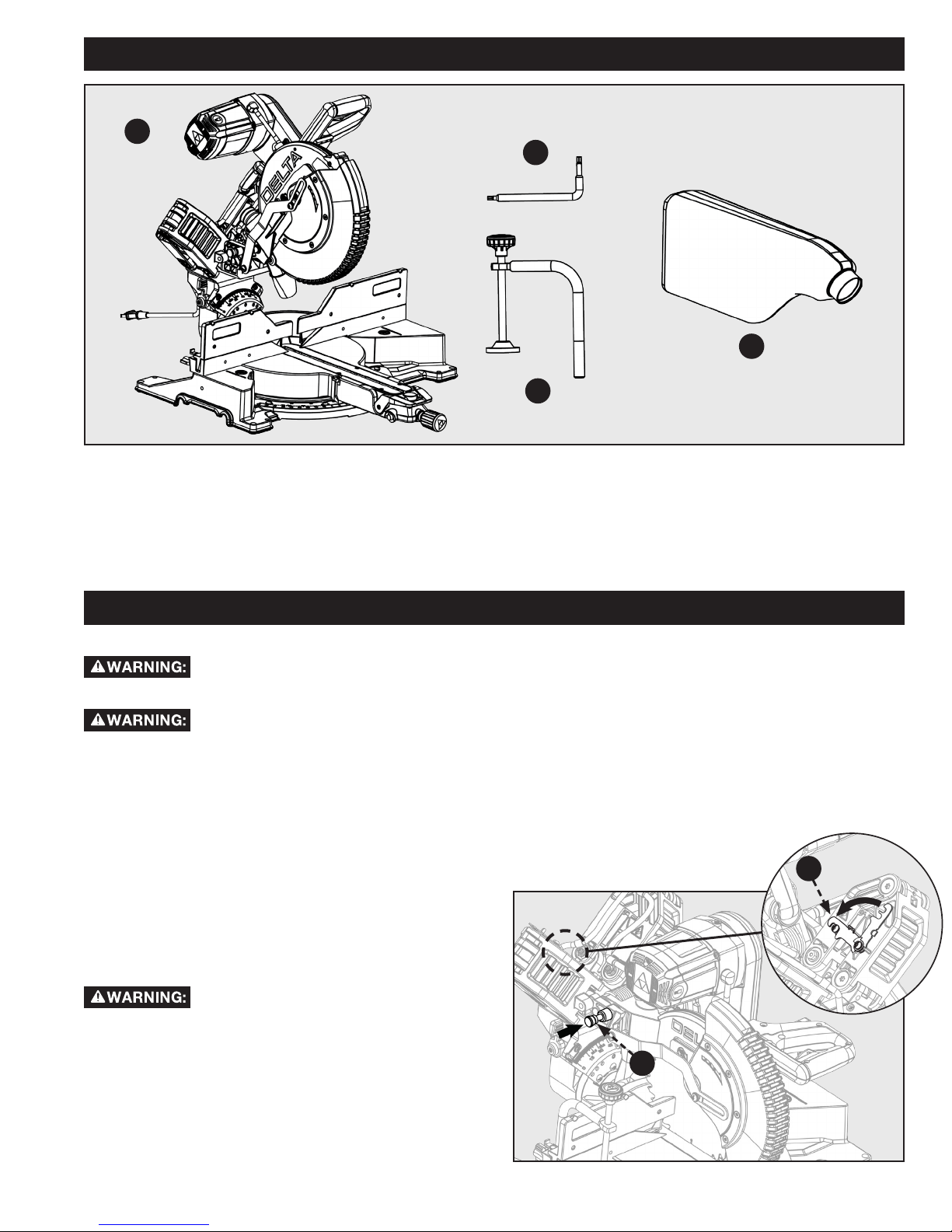
PACKAGED CONTENTS LIST
UNPACKING
B
D
C
Figure 3
A. Delta Cruzer 26-2250
B. Blade Wrench
C. Work Clamp
D. Dust Bag
MOUNTING AND TRANSPORTATION
Before moving/transporting your saw it is important to make sure all of the following steps have been followed to
ensure a safe condition for transportation. Failure to do so can result in serious personal injury.
• Always turn the power off and unplug saw before transporting.
• Secure power cord to avoid any snags or hang ups during transportation.
• Always lift using the strength of your legs to lift saw; never use your back muscles to lift saw.
• Do not use power On/Off switch handle or power cord to lift your saw.
• Always place the saw onto a stable and level surface with clearance for handling and maneuvering.
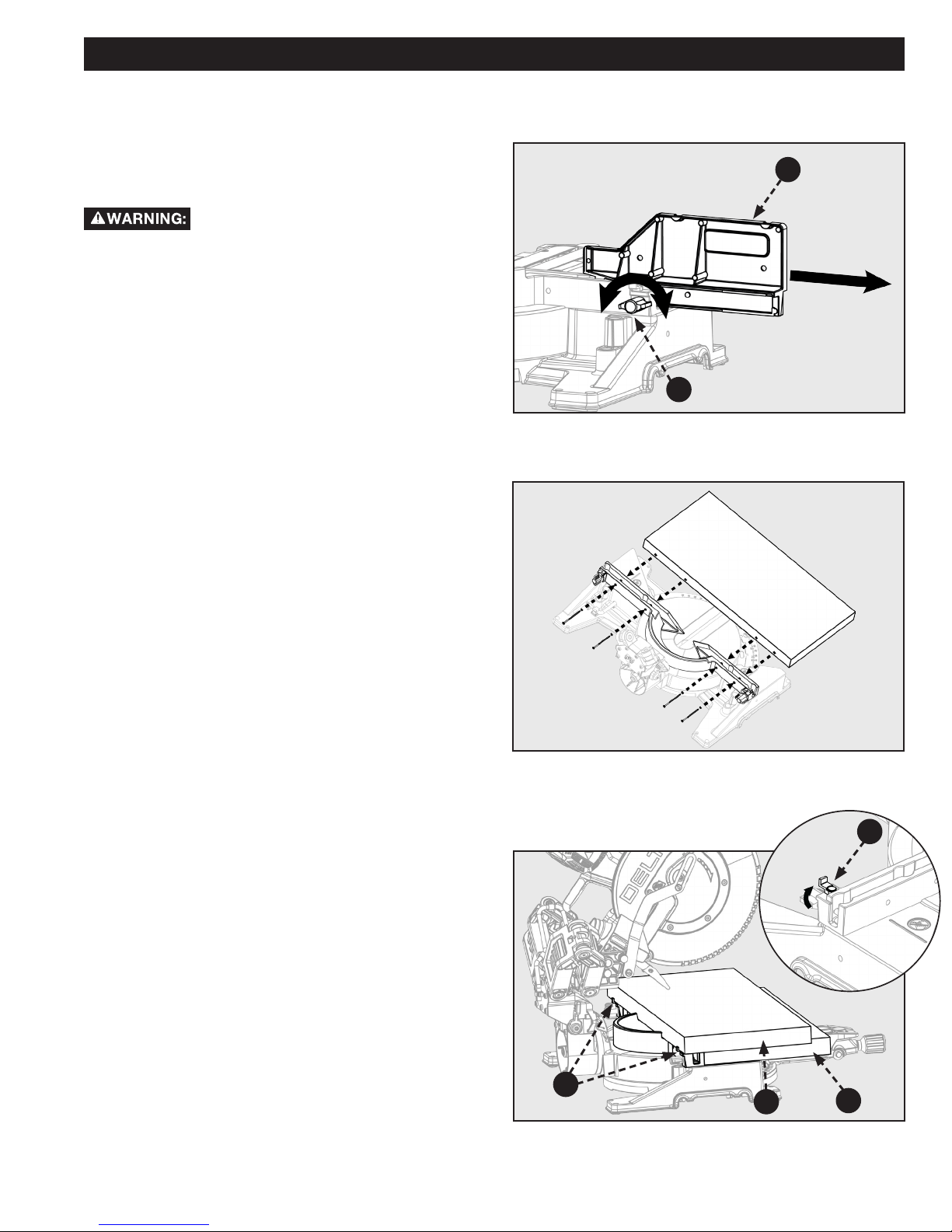
PREPARATIONS FOR TRANSPORTATION
SAW HEAD LOCK PIN
Always lock saw head in the down position before transporting
saw. To engage saw head lock pin (A): Push saw head to the
down position then push-in lock pin shown in Fig 4.
B
Saw Head lock pin is for storage and
transport only. This saw should never be locked in the down
position while making cuts.
SLIDE PREVENTION LOCK
Always engage the slide prevention lock (B) before
transporting this saw. To engage slide prevention lock: Push
saw head to the fully retracted position then swing the lock
link down as shown in Fig. 4.
A
Figure 4
9
Page 10
MOUNTING AND TRANSPORTATION
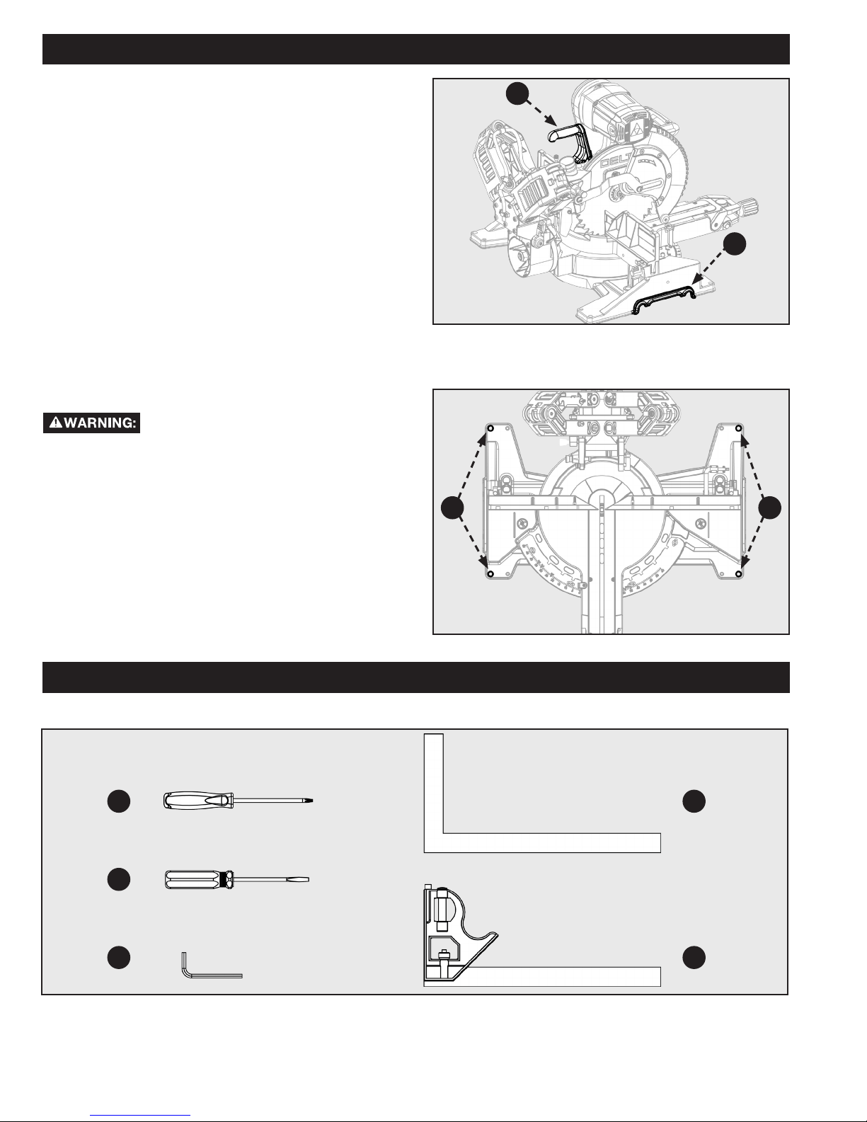
CARRY HANDLE
For transportation use the included carry handle (A) as shown
in Fig. 5 You may also lift using the cast-in handle cut-outs (B)
on both sides of the saw base as shown in Fig. 5
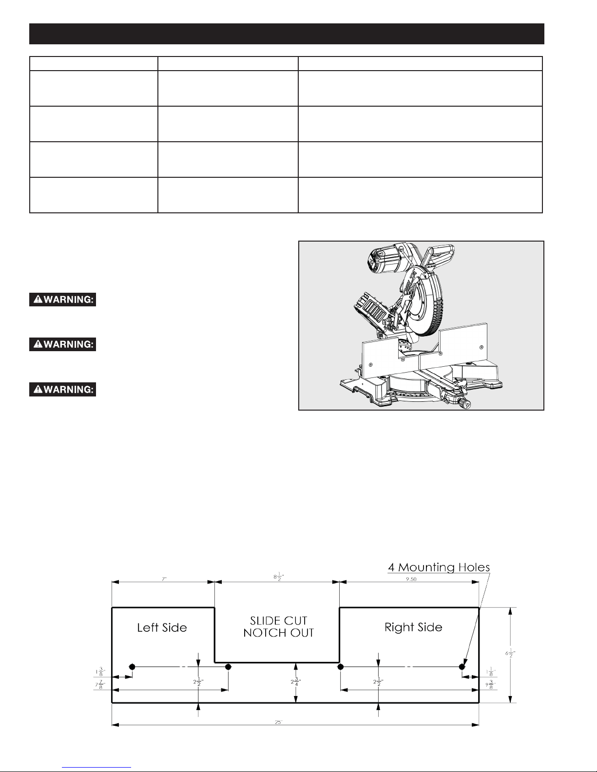
MOUNTING SAW TO STABLE SURFACE
To ensure safe and accurate operation, this
saw should be mounted to a stable and level surface such as a
workbench. To mount the tool to a stable surface, refer to
Figure 6 and do the following:
1. Locate the four mounting holes in the base of the saw
C.
2. Secure the tool to the mounting surface using 3/8”
diameter machine bolts, lock washers, and hex nuts
(not included). Make sure the bolts are long enough to
accommodate the saw base, lock washers, hex nuts,
and the thickness of the workbench.
3. Tighten all four bolts securely.
4. Check to make sure that the saw is secure before
operation.
A
B
Figure 5
C C
Figure 6
TOOLS NEEDED
A
B
C
A. T20 Torx Driver
B. Flat Head Drive
C. 5mm Hex Wrench
ASSEMBLY
D
E
Figure 7
D. Square
E. Combination Square
10 11
Page 11
ASSEMBLY
• Do not attempt to modify this tool or create accessories not recommended for use with this tool. Any such alteration or
modication is misuse and could result in a hazardous condition.
• Do not connect to power supply until assembly is complete. Failure to comply could result in accidental starting.
• Do not start the miter saw without checking for interference between the blade and the miter fence. Damage could result to the
blade if it strikes the miter fence during operation of the saw.
• The saw can tip over if the saw head is released suddenly and the saw is not secured to a work surface. ALWAYS secure this saw
to a stable work surface before any use.
• If any parts are damaged or missing do not operate this tool until the parts are replaced. Please call Customer Care Center at
800-223-7278, for instructions.
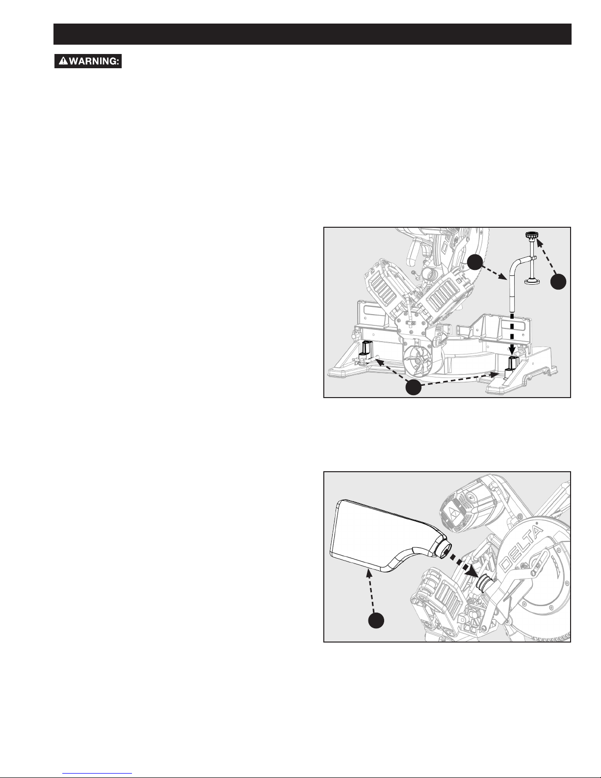
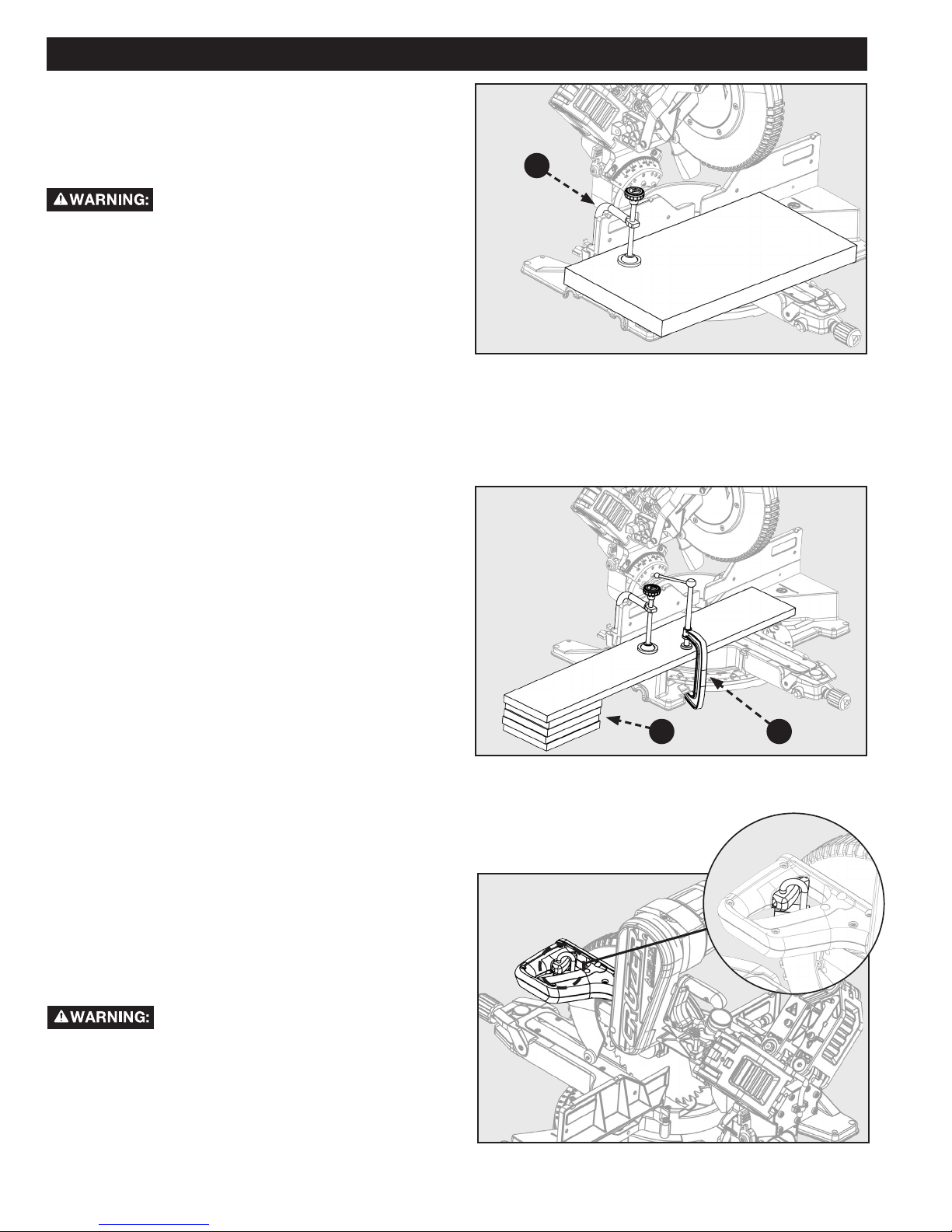
WORK CLAMP
The vertical work clamp secures the workpiece to the table to
provide more stability and keeps the workpiece from creeping
toward the saw blade.
To install the vertical work clamp, see Figure 8 and do the
following:
1. Place the clamp shaft (A) in either hole (B) on the miter
base.
2. Rotate the knob (C) on the clamp clockwise to move it
in or counter clockwise to move it out as needed.
A
C
DUST BAG
The Tool includes a dust collection bag (D) that attaches over
the exhaust port on the upper blade guard. Slide the plastic
collar onto the dust exhaust port on the back of the saw head.
See Figure 9
NOTE: To remove the dust bag for emptying, simply reverse
the above procedure.
B
Figure 8
D
Figure 9
11
Page 12
ASSEMBLY
INSTALL/REMOVE/REPLACE BLADE
A 12-inch blade is the maximum blade
capacity of the saw. Larger blades will come in contact with
the blade guards.
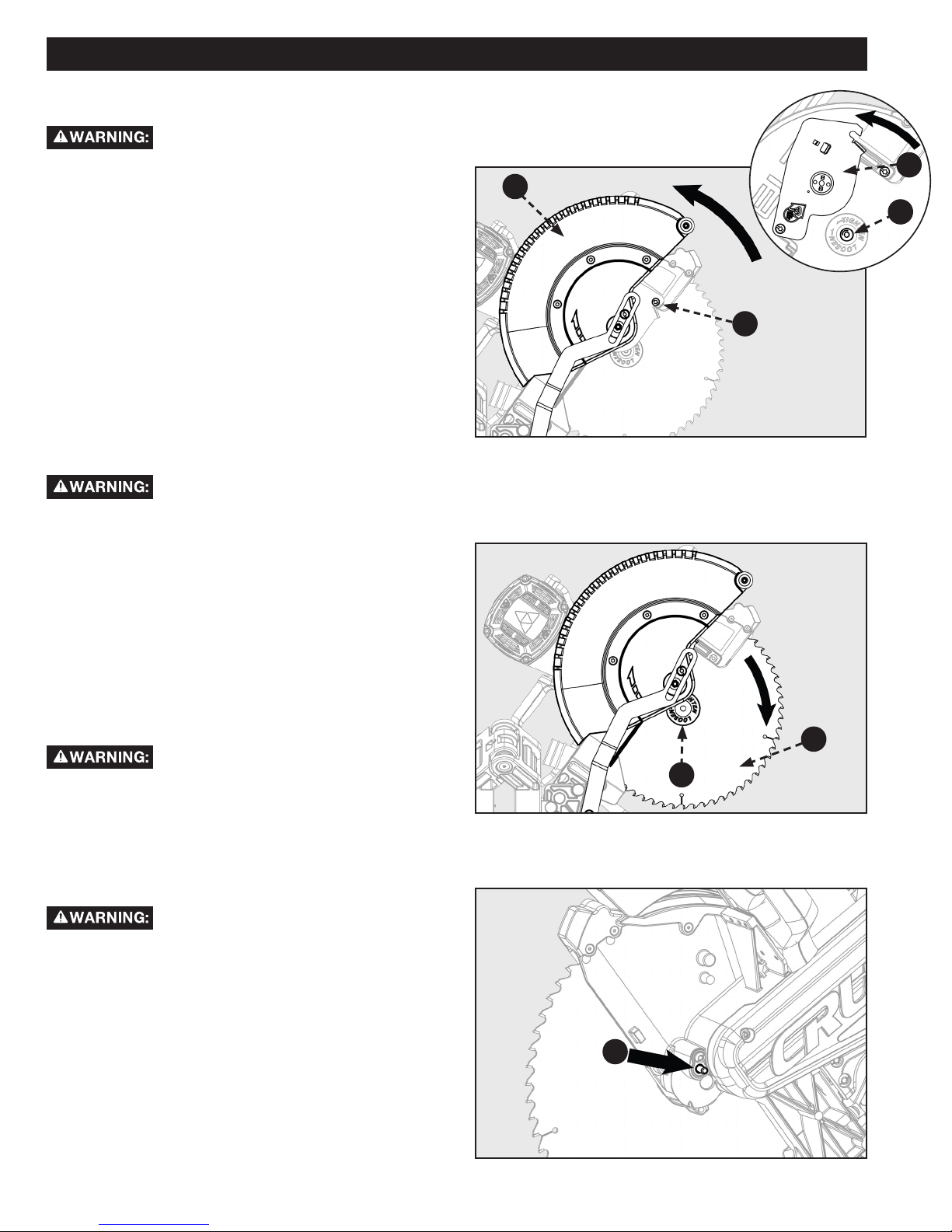
Refer to Figure 10.
1. Make sure the saw is unplugged.
2. Raise the saw arm to the full upright position.
3. Rotate the lower blade guard (A) up. Slightly loosen the
blade bolt cover screw (B) until you can move the blade
bolt cover (C) up to expose the blade bolt (D).
Refer to Figure 11.
4. If replacing the blade, carefully rotate the old blade until
the spindle locks in place.
5. Using the supplied blade wrench, remove the blade bolt
(D) by turning it clockwise.
NOTE: The blade bolt has left-hand threads.
6. Remove only the outer blade washer (F) and the blade
(G), leaving the inner blade washer on the spindle.
If inner blade washer has been removed,
replace it before placing blade on spindle. Failure to do so
could cause an accident since blade will not tighten properly.
7. Press the spindle lock button (E). See figure 12.
8. Carefully t saw blade inside the blade guard and guide
it onto the spindle, ensuring the teeth of the blade are
facing down at the front of the saw.
9. Align the double “D” ats on the blade washer (F) with
the ats on the spindle and t the washer onto the
spindle.
10. Lock the spindle by depressing the spindle lock button.
Screw on the blade bolt (D), remembering to thread it
counter clockwise. Tighten blade bolt securely using the
provided blade wrench.
Always install the blade with the blade teeth
and the arrow on the side of the blade pointing down at the
front of the saw. The direction of the blade rotation is also
stamped with an arrow on the upper blade guard.
11. Replace the blade bolt cover and tighten blade bolt
cover screw securely. Lower blade guard.
12. Raise and lower the saw arm to ensure that the arm
and blade guard move freely.
Make sure the spindle lock button is not
engaged before reconnecting saw to power source. Never
engage spindle lock button when blade is rotating.
C
A
D
B
Figure 10
G
F
Figure 11
Figure xx
NOTE: Some illustrations in this manual indicate only portions
of the saw. This is done in order to more clearly show key
areas and components of the saw. Never operate the saw
without all guards securely in place and in good operating
condition.
E
Figure 12
12 13
Page 13

OPERATION
• Do not allow familiarity with tools to make you careless. Remember that a careless fraction of a second is sufcient enough to
inict serious personal injury.
• Always wear eye protection with side shields and marked to comply with ANSI Z87.1 Failure to do so could result in objects being
thrown into your eyes, resulting in possible serious personal injury.
• Do not use any attachments or accessories not recommended by the manufacturer of this tool. The use of attachments or
accessories not recommended can result in serious personal injury.
• Before starting any cutting operation, clamp or bolt the compound miter saw to a workbench. Never operate the miter saw on
the oor or in a crouched position. Failure to heed this warning can result in serious personal injury.
• To avoid serious personal injury, always tighten the miter lock handle and bevel lock knob securely before making a cut. Failure
to do so could result in movement of the control arm or miter table while making a cut.
• To avoid serious personal injury, keep hands outside the no hands zone, at least 3 in. from blade. Never perform any cutting
operation freehand (without holding workpiece against the fence). The blade could grab the workpiece if it slips or twists.
• When using a work clamp or C-clamp to secure the workpiece, clamp workpiece on one side of the blade only. The workpiece
must remain free on one side of the blade to prevent the blade from binding in workpiece. The workpiece binding the blade will
cause motor stalling and kickback. This situation could cause an accident resulting in serious personal injury.
• NEVER move the workpiece or make adjustment to any cutting angle while the saw is running and the blade is rotating. Any slip
can result in contact with the blade causing serious personal injury.
You may use this tool for the following purposes:
• Bevel cutting and compound cutting for crown moldings, etc.
• Cross cutting wood and plastic.
• Cross cutting for moldings, door casings, picture frames, etc.
CUTTING WARPED MATERIAL
When attempting to cut warped material, the CONVEX face
should be against the fence as shown in Figure 13.
Never position a piece of warped material with the CONCAVE
face or edge against the fence, as shown in Figure 14. It will
pinch the blade near the completion of the cut.
To avoid a kickback and to avoid serious
personal injury, never position the concave edge of bowed or
warped material against the fence.
Figure 13
Figure 14
13
Page 14
OPERATION
CLAMPING WIDE WORKPIECES
When cutting wide work pieces, such as 2 in. X 12 in., clamp
the workpiece to the work table using a work clamp (A) as
shown in Figure 15.
Keep clamps away from the path of the
blade and blade guard assembly.
SUPPORTING LONG WORKPIECES
In most cases the included table extensions (workpiece
supports) will be sufficient to support longer workpieces. If
these are not long enough, the workpiece should be supported
further out from the saw. Additional support (B) may be used
to make the workpiece lay flat on the saw table. Use the
included work clamp or a C-clamp (C) to secure the workpiece
to the miter saw table. See Figure 16.
A
Figure 15
POWER SWITCH LOCK
To prevent any unauthorized person from operating this saw,
a padlock (not included) should be installed into the lock hole
located on the power switch, as shown in Figure 17. Be sure
padlock is fully closed and locked before leaving this saw
unattended.
Always disconnect the power supply before
installing or removing a lock onto the power switch. Failure
to do so could cause the power switch to engage by accident,
resulting in serious injury.
B
Figure 16
Figure 17
C
14 15
Page 15
OPERATION
Before turning the saw power ON, check to
make sure saw head and blade will not make contact with the
provided work clamp or fence during the cutting operation.
Position the work clamp and fence to avoid contact with the
miter saw head.
NON-SLIDING CUTS
Always engage the slide prevention lock
before making any non-sliding cuts. Failure to engage this lock
could result in saw head movement during the cutting
operation.
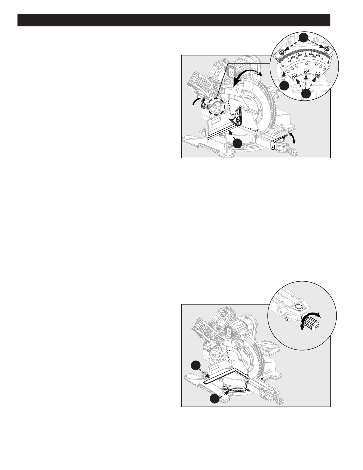
FOR CROSS CUTS
1. See Figure 18
2. To use this saw as a traditional, non-sliding, miter saw:
slide the saw head into the fully retracted position and
engage the slide prevention lock
3. Loosen the miter lock knob (A), use your thumb to push
in the miter detent lock button (B), and set the miter
arm angle to 0 degrees. Use the miter scale (C) and
indicator (D) to locate the 0 degree miter position.
4. Release the miter detent button (B) and tighten the
miter lock knob (A). Check that saw head is securely
locked into position.
5. Raise the saw head to its UP position.
6. Position the workpiece so that it is securely supported
by the saw table and fence. If the board is warped,
read and follow the instructions under “Cutting Warped
Material” in the “Operation” section of this manual.
7. Secure the workpiece to the table and against the fence,
using the provided clamp.
8. Before turning the power switch ON, perform a
simulated cut to check your cut alignment. Also check
to make sure the blade will not come into contact with
the provided work clamp or anything other than the
workpiece.
9. Engage the power ON switch. Allow the blade to reach
maximum speed.
10. Lower the saw blade through the workpiece.
11. Disengage the power switch and allow blade to come to
a complete stop before raising the saw head.
FOR MITER CUTS
Before turning the saw power ON, check to
make sure saw head and blade will not make contact with the
provided work clamp or fence during the cutting operation.
Position the work clamp and fence to avoid contact with the
miter saw head.
B
LOCK
C
Figure 18
UNLOCK
D
A
F
LOCK
UNLOCK
G
Figure 19
NOTE: If your required miter angle position is not provided
with one of the positive stop miter detent positions; you can
use the miter detent override (G). To engage the miter detent
override, push in the miter detent button (F) and push in the
miter detent override. Tighten the miter lock knob before
cutting.
E
Always tighten the miter lock knob (E) before
any cutting operation. Failure to do so may result in serious
personal injury.
See Figure 19
1. Follow Operation instructions “For Cross-Cuts” in
previous manual section. Include the following
adjustments before cutting.
2. Rotate miter arm to required miter angle other than 0
degrees.
15
Page 16

OPERATION
FOR BEVEL CUTS
Before turning the saw power ON, check to
make sure saw head and blade will not make contact with the
provided work clamp or fence during the cutting operation.
Position the work clamp and fence to avoid contact with the
miter saw head.
Always lock the bevel lock handle before
any cutting operation. Failure to do so may result in serious
personal injury.
See Figure 20
1. Follow Operation instructions “For Cross-Cuts” in
previous manual section. Include the following
adjustments before cutting.
2. Loosen fence lock knob (A) on left and right side, and
slide adjustable fence (B) to allow proper spacing for
bevel cuts. Once proper spacing is set, tighten fence
lock knob
3. Lift the bevel lock handle (C)
4. While rmly supporting the saw head with one hand,
push back the bevel latch lever (D) and swing the saw
head left or right to the required bevel angle.
5. If you are using one of the bevel detent positions, check
to make sure the bevel latch lever and bevel detent
locks into the positive stop plate.
6. Push down the bevel lock handle to lock bevel position.
C
Figure 20
LOCK
UNLOCK
UNLOCK
D
B
A
LOCK
NOTE: If your required bevel angle position is not provided
with one of the positive stop bevel detent position; you can
lock the bevel position at any location using the bevel lock
handle (C).
FOR COMPOUND MITER CUTS
Before turning the saw power ON, check to
make sure saw head and blade will not make contact with the
provided work clamp or fence during the cutting operation.
Position the work clamp and fence to avoid contact with the
miter saw head.
See Figure 21
A compound miter cut uses a combination of a miter angle
adjustment and bevel angle adjustment. Use the instructions
above “For Miter Cuts” and “For Bevel Cuts” to set your
bevel and miter angle before performing the “For Cross-cuts”
operation instructions above.
NOTE: The miter angle and bevel angle are dependent upon
each other. If you adjust one of these it will change the other.
Always check both angles after making any adjustments.
Figure 21
16 17
Page 17
OPERATION
SLIDE CUTS
A slide cut should never be performed by
pulling the saw toward you. Due to the blade rotation
direction, this can cause the saw blade to climb over the
workpiece and towards the operator. Failure to follow this
warning could result in serious personal injury.
Before turning the saw power ON, check to
make sure saw head and blade will not make contact with the
provided work clamp or fence during the cutting operation.
Position the work clamp and fence to avoid contact with the
miter saw head.
See Figure 22
To use this saw to make slide cuts follow the instructions
below. Slide cuts must only be performed by pushing the saw
blade away from you and toward the back of the saw, stopping
at the fully RETRACTED position after each cut. See warning
above.
1. Check to make sure the slide prevention lock (B) and head
lock pin (A) is not engaged. Raise the saw head to its UP
position.
2. Position the workpiece so that it is securely supported by
the saw table and fence. If the board is warped, read and
follow the instructions under “Cutting Warped Material” in
the “Operation” section of this manual.
3. Secure the workpiece to the table and against the fence,
using the provided clamp.
4. Before turning the power switch ON, perform a simulated
cut to check your cut alignment. Also check to make sure
the blade will not come into contact with the provided
work clamp or anything other than the workpiece.
5. Before turning the power switch ON, pull the saw arm
towards you until the blade is beyond the front edge
of your workpiece or until the saw arm is in the fully
EXTENDED position. The saw head should be in the full UP
position.
6. Engage the power ON switch. Allow the blade to reach
maximum speed.
7. Lower the saw blade through the workpiece and push the
saw head towards the fully RETRACTED position.
8. Disengage the power switch and allow blade to come to a
complete stop before raising the saw head.
1
A
2
Figure 22
B
Figure 23
TIPS FOR CUTTING CROWN MOLDING
• The two edges of the molding that contact the ceiling and the wall are at angles that, when added together, equal exactly 90°.
Most crown molding has a top rear angle (the section that ts at against the ceiling) of 52° and a bottom rear angle (the
section that ts at against the wall) of 38°.
• To accurately cut crown molding for a 90° inside or outside corner, lay the molding with its broad back surface at on the miter
table and against the fence.
• The angles for crown moldings must be very precise. The bevel and miter angles are interdependent; changing one angle
changes the other angle as well.
• Since it is very easy for the work piece to shift, all settings should rst be tested on scrap molding. Also most walls do not have
angles of exactly 90°; therefore, you will need to ne-tune your settings.
• When cutting crown molding the bevel angle should be set at 33.85°.
• The miter angle should be set at 31.62° either right or left, depending on the desired cut for the application. See the chart
below for correct angle settings and correct positioning of crown molding on the work table.
17
Page 18
OPERATION
Bevel Angle Setting Type of Cut Steps
33.85° Left side, inside corner 1. Top edge of molding against fence
2. Miter table set right 31.62°
3. Save left end of cut
33.85° Right side, inside corner 1. Bottom edge of molding against fence
2. Miter table set left 31.62°
3. Save left end of cut
33.85° Left side, outside corner 1. Bottom edge of molding against fence
2. Miter table set left 31.62°
3. Save right end of cut
33.85° Right side, outside corner 1. Top edge of molding against fence
2. Miter table set right 31.62°
3. Save right end of cut
AUXILIARY FENCE
For cutting certain workpieces, you may require a larger fence
surface area to accommodate the workpiece. The auxiliary
fence should be made using 3/4” thick wood. Use the holes
which are pre-drilled in the fence to attach an auxiliary fence.
Never use auxiliary fence which interferes or
makes contact with saw head. Always check for clearance
between auxiliary fence and saw head before making cuts.
To make slide cuts using an auxiliary fence, a
notch must be cut out in the auxiliary fence prior to attaching
to saw fence.
The auxiliary fence can only be used with the
0 degree bevel angle. Remove the auxiliary fence before
making a bevel cut.
Figure 24
1. See gure 25 for auxiliary fence dimensions.
2. Place auxiliary fence wood against miter saw fence. See gure 24. The maximum height for this wood must not exceed
6.5”. Check to make sure auxiliary fence does make contact with saw head, check with saw head in the full DOWN and fully
RETRACTED position.
3. Mark the hole locations on the backside of the auxiliary fence board.
4. Drill the marked hole locations all the way through the auxiliary fence. Countersink the drilled holes on the front side of your
auxiliary fence board.
5. Fasten the auxiliary fence using at head screws. Secure from behind using at washers and nuts.
6. Make a full depth cut through the auxiliary fence, to create the blade slot.
7. The notch shown in gure 25 must be cut out in order to make slide cuts using the auxiliary fence.
Figure 25
18 19
Page 19
OPERATION
INCREASE CUT CAPACITY
This saw is designed to allow for large capacity cuts up to (2”
x 18”). In order to make these cuts you will need to configure
your saw appropriately.
Do not use an auxiliary table board which will
not fully support the workpiece during cutting operation.
1. Loosen the fence lock knob (A). Slide the upper
(adjustable) fence (B) completely out of its track and set
to the side. See Figure 26.
2. Flip the support tabs (C) into position. Tabs (C) are on
both the left and right sides of the lower (xed) fence.
These will function as your workpiece backstop. See
Figure 28.
3. You will need to add an auxiliary table board (D) to
support your large capacity workpiece (E). Place a 2”
x 14” auxiliary table board (D) onto the saw table and
against the lower (xed) section of the saw fence. Make
sure the board is securely positioned against the lower
(xed) fence.
NOTE: Use wood screws to secure the auxillary table board
(D) to the lower (xed) fence. See Figure 27.
LOOSEN
B
TIGHTEN
A
Figure 26
4. Use the support tabs (C) to secure your workpiece
before making any cuts
Figure 27
C
19
C
E
Figure 28
D
Page 20
ADJUSTMENTS
ALIGN BLADE TO TABLE
Your saw is calibrated at the factory to cut true. Over time the
saw’s calibration may drift and will need to be re-calibrated.
See Figure 29
1. Unplug the Saw
2. Lower the saw head all the way down to the transport
position and engage the saw head lock pin to hold it
in place. Push the saw head into the fully retracted
position and engage the slide prevention lock to hold it
in place.
3. Set the miter position to 0 degrees and engage the
miter lock knob so the table will not move.
4. Set the bevel position to 0 degrees. Engage the bevel
latch lever, so the detent pin locks into the bevel detent
plate.
5. Place a combination square (A) against the table and
the face of the saw blade .
NOTE: Make sure the square contacts the flat part of the
blade and not the teeth.
6. Rotate the blade by hand and check the blade-to-table
alignment at several points. If the blade face is not ush
with the square you will need to adjust the bevel detent
plate.(B)
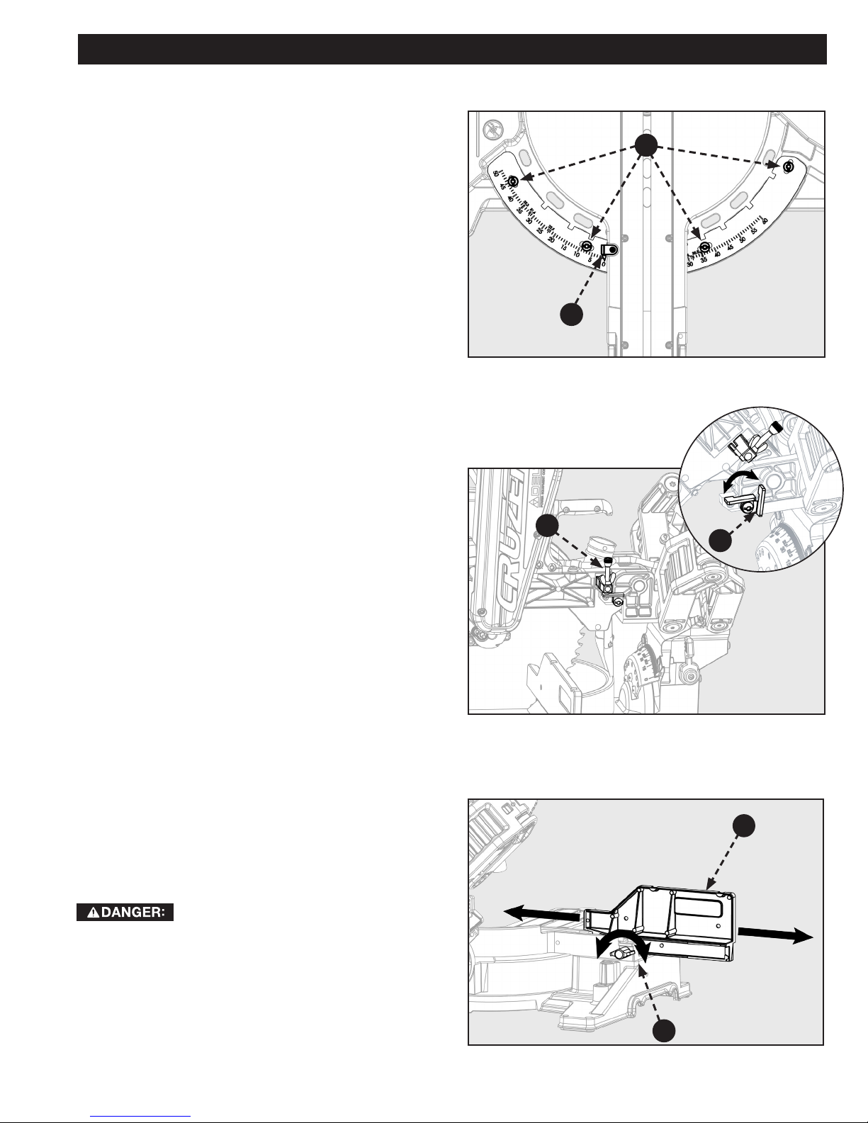
7. Loosen the three screws (C) and adjust the bevel detent
plate position. Set so the table and blade are flush
against the combination square. Make sure the bevel
lock/unlock handle is not locked, so the detent plate
may be adjusted.
8. Re-tighten the three screws and re-check the blade-to-
table alignment.
NOTE: This saw has two scale indicators, one on the bevel
scale and one on the miter scale. After squaring adjustment
have been made, it may be necessary to loosen the indicator
screws (D) and reset them to zero
A
Figure 29
D
B
C
UNLOCK
LOCK
ALIGN BLADE TO FENCE
Your saw is calibrated at the factory to cut true. Overtime the
saw’s calibration may drift and will need to be re-calibrated.
See Figure 30
1. Unplug the Saw
2. Lower the saw head all the way down to the transport
position and engage the saw head lock pin to hold it
in place. Push the saw head into the fully retracted
position and engage the slide prevention link to hold it
in place.
3. Set the miter position to 0 degrees and allow the miter
detent to lock into position.
4. Set the bevel position to 0 degrees. Engage the bevel
lock handle to lock bevel angle.
5. Place a square (E) against the fence and the face of the
saw blade .
INSTRUCTIONS CONTINUED ON NEXT PAGE
LOCK
UNLOCK
E
F
Figure 30
20 21
Page 21
ADJUSTMENTS
ALIGN BLADE TO FENCE CONT’D
NOTE: Make sure the square contacts the flat part of the
blade and not the teeth.
6. If the blade face is not ush with the square you will
need to adjust the miter detent plate
See Figure 31
7. Loosen the four screws (A) and move the miter table to
adjust the miter detent plate position. Set so the fence
and blade are ush against the combination square.
Make sure the miter lock knob is not locked, so the
miter detent plate may be adjusted.
8. Re-tighten the four screws and re-check the blade-to-
fence alignment.
NOTE: This saw has two scale indicators, one on the bevel
scale and one on the miter scale. After squaring adjustment
have been made, it may be necessary to loosen the indicator
screws (B) and reset them to zero.
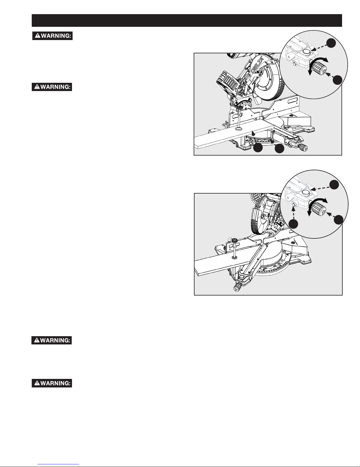
DEPTH STOP ADJUSTMENT
This miter saw is equipped with an adjustable depth stop for
making through cuts and non-through cuts.
Refer to Figure 32 and follow these instructions in
order to set the depth stop at a specific cut depth:
rotate the stop bracket (C) counterclockwise into the down
position. The cut depth can now be adjusted by turning the
depth adjustment screw (D).
Refer to figure 32 and follow these instructions in
order to make a through cut: rotate the stop bracket (C)
clockwise into the up position.
A
B
Figure 31
D
C
FENCE EXTENSION
This saw is equipped with an adjustable extension fence.
To extend or retract the fence refer to Figure 33 and follow
these instructions: Loosen the lock knob (E) by rotating
counterclockwise and the slide the fence (F) into the desired
position. Make sure to re-righten lock knob (E) by rotating
clockwise.
Always check to make sure lock knob (E) is
tightened before making a cut. Failure to do so may result in
injury.
21
LOOSEN
Figure 32
F
TIGHTEN
E
Figure 33
Page 22

ADJUSTMENTS
SLIDE RESISTANCE
See Figure 34
The slide resistance (friction) on your saw is adjustable. Use an
5mm Hex wrench. Locate the friction adjustment screw on the
saw arms (A). Turn right to tighten the sliding friction. Turn left
to loosen the sliding friction.
A
Figure 34
LOOSEN
TIGHTEN
THROAT PLATE
Only use Delta® authorized service parts.
Using non-authorized parts can results in damage to your
machine and serious personal injury.
In the even that your throat plate needs to be replaced for any
reason, follow these instruction. See figures 35 and 36.
1. Loosen the fence lock knobs. Slide both of the upper
(adjustable) fences completely off the lower (fixed)
fence.
2. Remove the four screws (B) in the lower (xed) fence
(C). Lift the fence off of the saw.
3. Remove the six screws (D) which hold the throat plate.
Lift the throat plate off the miter arm.
4. Replace the throat plate only using a Delta® authorized
service part.
5. Tighten the six screws (D) which holed the throat plate.
6. Re-install the lower (xed) fence and tighten the four
screws (B) which hold it.
B
C
Figure 35
D
Figure 36
22 23
Page 23

MAINTENANCE
To reduce the risk of injury, turn unit off and
disconnect it from power source before cleaning or servicing,
before installing and removing accessories, before adjusting
when making repairs. An accidental start-up can cause injury.
KEEP MACHINE CLEAN
Periodically blow out all air passages with dry
compressed air. All plastic parts should be cleaned with a soft
damp cloth. NEVER use solvents to clean plastic parts. They
could possibly dissolve or otherwise damage the material.
Wear certified safety equipment for eye, hearing and
respiratory protection while using compressed air.
Empty dust bag frequently.
When servicing, use only identical replacement parts. Use of
any other parts may create a hazard or cause product damage.
GENERAL MAINTENANCE
Avoid using solvents when cleaning plastic parts. Most plastics
are susceptible to damage from various types of commercial
solvents and may be damaged by their use. Use clean cloths to
remove dirt, dust, oil, grease, etc.
BRUSH REPLACEMENT
Do not at any time let brake fluids, gasoline,
petroleum-based products, penetrating oils, etc., come in
contact with plastic parts. Chemicals can damage, weaken or
destroy plastic which may result in serious personal injury.
Electric tools used on fiberglass material, wallboard,
spackling compounds, or plaster are subject to accelerated
wear and possible premature failure because the fiberglass
chips and grindings are highly abrasive to bearings, brushes,
commutator, etc. Consequently, we do not recommend using
this tool for extended work on these types of materials.
However, if you do work with any of these materials, it is
extremely important to clean the tool using compressed air.
LUBRICATION
All of the bearings in this tool are lubricated with a sufficient
amount of high-grade lubricant for the life of the unit under
normal operating conditions. Therefore, no further lubrication
is required.
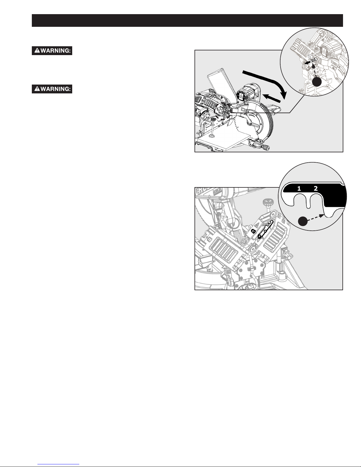
The motor on this saw features externally accessible brush
assemblies that should be periodically checked for wear. If the
brushes need to be replaced, refer to Figure 36 and proceed as
follows:
Unplug the saw.
Failure to unplug the saw could result in
accidental starting causing serious personal injury.
Loosen Screws (A) and remove motor end cap (B). Using a flat
head carefully remove the brush cap (C).
NOTE: Remove the cap slowly. The brush assembly is spring-
loaded and will pop out once the cap is removed.
Remove brush assembly (D).
Inspect both brushes. If either has less than 1/4 in. length of
carbon remaining, both brushes should be replaced.
NOTE: Do not replace one side without replacing the other.
Insert both brushes into the brush tube (E), making sure the
curvature of the brushes matches curvature of motor. Brush
assembly should move freely within the tube.
Carefully replace the brush cap, ensuring that it is not crossthreaded.
Tighten brush cap securely. Do not over-tighten.
E
A
D
C
B
Figure 37
FAILURE TO START
If your machine fails to start, check to make sure the prongs on the cord plug are making good contact in the receptacle. Also,
check for blown fuses or open circuit breakers in your power supply line. If the saw still does not start, call Company’s Customer
Care Center at 1-800-223-7278.
TROUBLESHOOTING
23
Page 24

ACCESSORIES
For accessories please visit our Web Site for an on-line catalog or for the name or your nearest supplier.
Since accessories other than those offered by DELTA ® have not been testes with this product, use of such
accessories could be hazardous. For safest operation, only DELTA
®
recommended accessories should be used with this product
PARTS, SERVICE OR WARRANTY ASSISTANCE
All CRUZER Machines and accessories are manufactured to high quality standards and are serviced by a network of an Authorized
Service Centers. To obtain additional information regarding your product or to obtain parts, service, warranty assistance, or the
location of the nearest service center, please call 1-800-223-7278.
Five Year Limited Warranty
1. WHAT IS COVERED. Delta Power Equipment Corporation (“Company”) will, at its option, repair or replace this product, if purchased
at retail in the United States or Canada and the product, with normal use, has proven to be defective in workmanship or material, subject to
the conditions stated in this Limited Warranty. This Limited Warranty covers only materials and labor. All transportation costs are Customer’s
responsibility.
2. WARRANTY PERIOD. All warranty claims must be submitted within three years from the date of retail purchase. For all service parts
and factory refurbished products, the warranty period is 180 days.
3. HOW TO OBTAIN SERVICE. To obtain warranty service, you must return the defective product, at your expense, to a service center
authorized by Company to perform warranty service (a “Company Authorized Service Center”) within the applicable warranty period, together
with acceptable proof of purchase, such as your original receipt bearing the date of purchase, or product registration number. Company reserves
the right to restrict warranty claim service to the country where the purchase was made and/or to charge for the cost to export service parts or
provide warranty service in a different country. For this purpose, on-line purchases are deemed made in the United States. For the location of
your nearest Company Authorized Service Center, call Company’s Customer Care Center at (800) 223-7278.
4. EXCLUSIONS.
● Company does not offer any warranty on products purchased in used or damaged condition.
● Company does not warrant any products purchased outside the United States or Canada
● Company will not be responsible for any damage that has resulted from normal wear, misuse, abuse or any repair or alteration made by
anyone other than a Company Authorized Service Center or a designated representative of Company’s Customer Care Center.
All IMPLIED WARRANTIES are expressly limited to the warranty period identied above.
Company will not be liable for INCIDENTAL OR CONSEQUENTIAL damages.
This limited warranty is Company’s sole warranty and sets forth the customer’s exclusive remedy with respect to defective products; all other
warranties, express or implied, whether of merchantability, tness for purpose, or otherwise, are expressly disclaimed by Company, except as
expressly stated in this warranty statement.
Some states do not allow the exclusion or limitation of incidental or consequential damages, or the limitation of implied warranties, so the above
limitations or exclusions may not apply to you. This warranty gives you specic legal rights and you may have other rights which vary in certain
states or provinces. For further details of warranty coverage and warranty repair information, call (800) 223-7278. To register your products
on-line, we encourage you to visit our website and register for a FREE DELTA® Member Account at http://www.deltamachinery.com/register.
LATIN AMERICA: This warranty does not apply to products sold in Latin America. For products sold in Latin America, call the
local company or see website for warranty information.
REPLACEMENT PARTS
Use only identical replacement parts. For a parts list or to order parts, visit our website at www.DeltaMachinery.com/service. You can
also order parts from your nearest Authorized Warranty Service Center or by calling Technical Service Manager at 1-800-223-7278 to
receive personalized support from one of our highly-trained representatives.
FREE WARNING LABEL REPLACEMENT
If your warning labels become illegible or are missing, call 1-800-223-7278 for a free replacement.
SERVICE AND REPAIRS
All quality tools will eventually require servicing and/or replacement of parts. For information about Delta Power Equipment
Corporation, its factory-owned branches, or to locate an Authorized Warranty Service Center, visit our website at
www.DeltaMachinery.com/service or call Customer Care at 1-800-223-7278. All repairs made by our service centers are fully
guaranteed against defective material and workmanship. We cannot guarantee repairs made or attempted by others. By calling this
number you can also nd answers to most frequently asked questions 24 hours/day.
You can also write to us for information at Delta Power Equipment Corporation, 2651 New Cut Road, Spartanburg, SC 29303 Attention: Technical Service Manager. Be sure to indicate all of the information shown on the nameplate of your saw (model number,
type, serial number, date code, etc.).
24 25
Page 25

12-inch Sliding Compound Miter Saw
Scie à onglets composée coulissante 12 pouces
Sierra de inglete compuesta deslizante de 12 pulgadas
Français (25)
Español (49)
www.DeltaMachinery.com
Instruction Manual
Manual d’utilisation
Manual de instrucciones
AVERTISSEMENT :
Pour réduire les risques de blessure grave, veuillez lire attentivement et respecter toutes les mises en garde et directives dans
ce guide et sur le produit.
CONSERVEZ CE GUIDE PRÈS DE VOTRE PRODUIT POUR FACILITER LA CONSULTATION ET POUR INFORMER LES AUTRES.
26-2250
25
Page 26

TABLE DES MATIÈRES
CONSIGNES IMPORTANTES DE SÉCURITÉ .............26
LOGOS DE SÉCURITÉ ...................................................26
RÈGLES DE SÉCURITÉ GÉNÉRALES POUR LES
OUTILS ÉLECTRIQUES .................................................27
AVERTISSEMENT DE LA PROPOSITION 65 : ..........28
RÈGLES DE SÉCURITÉ DE LA SCIE À ONGLETS ......28
BRANCHEMENTS D’ALIMENTATION.........................29
DOUBLE ISOLATION ......................................................29
BRANCHEMENT ÉLECTRIQUE .........................................30
FICHES POLARISÉES .....................................................30
RALLONGES ..................................................................30
FONCTIONS ...................................................................30
SPÉCIFICATIONS DU PRODUIT ......................................30
APPRENEZ À CONNAÎTRE VOTRE SCIE À ONGLETS
COMBINÉE ...................................................................32
DÉBALLAGE ....................................................................32
ENLÈVEMENT DU CONTENU DE LA BOÎTE ......................32
LISTE DU CONTENU DE LA BOÎTE ..................................33
ASSEMBLAGE ET TRANSPORT ...................................33
PRÉPARATIONS POUR LE TRANSPORT ...........................33
MONTAGE DE LA SCIE SUR UNE SURFACE STABLE ..........34
MONTAGE .......................................................................34
OUTILS REQUIS ............................................................34
ÉTAU ............................................................................35
SAC À POUSSIÈRES .......................................................35
INSTALLER/ENLEVER/REMPLACER LA LAME ....................36
UTILISATION ................................................................37
COUPE DE MATÉRIAU GAUCHI .......................................37
SERRAGE DES GRANDES PIÈCES ...................................38
SOUTIEN DES LONGUES PIÈCES ....................................38
VERROUILLAGE DU COMMUTATEUR ...............................38
REMARQUE : La couverture du guide d’utilisation illustre le modèle du produit actuel. Toutes les autres illustrations contenues
dans le manuel sont uniquement à titre indicatif et peuvent ne pas être des représentations exactes de l’étiquetage réel ou des
accessoires inclus. Elles sont destinées à titre indicatif seulement.
COUPES NON COULISSANTES ........................................39
POUR LES COUPES D’ONGLET .......................................39
POUR LES COUPES EN BISEAU ......................................40
POUR DES COUPES D’ONGLET COMBINÉES ....................40
COUPES EN GLISSIÈRE .................................................41
CONSEILS POUR COUPE DE MOULURE COURONNÉE .......41
GUIDE AUXILIAIRE .......................................................42
AUGMENTER LA CAPACITÉ DE LA COUPE .......................43
RÉGLAGES ......................................................................44
ALIGNEMENT DE LA LAME AVEC LA TABLE .....................44
ALIGNEMENT DE LA LAME AVEC LE GUIDE .....................44
ALIGNEMENT DE LA LAME AVEC LA TABLE SUITE ...........45
RÉGLAGE DE LA BUTÉE DE PROFONDEUR ......................45
RALLONGE DU GUIDE ...................................................45
RÉSISTANCE AU GLISSEMENT .......................................46
PASSE-LAME .................................................................46
ENTRETIEN ....................................................................47
TENIR LA MACHINE PROPRE .........................................47
ENTRETIEN GÉNÉRAL ...................................................47
LUBRIFICATION ............................................................47
REMPLACEMENT DES BROSSES .....................................47
DÉPANNAGE ..................................................................47
DÉMARRAGE IMPOSSIBLE .............................................47
ACCESSOIRES ...............................................................48
ASSISTANCE POUR PIÈCES, SERVICE OU
GARANTIE ......................................................................48
PIÈCES DE REMPLACEMENT ..........................................48
REMPLACEMENT GRATUIT DES ÉTIQUETTES DE
SÉCURITÉ ....................................................................48
ENTRETIEN ET RÉPARATIONS .......................................48
FRANÇAIS ......................................................................25
ESPAÑOL ........................................................................49
CONSIGNES IMPORTANTES DE SÉCURITÉ
AVERTISSEMENT :
LIRE ATTENTIVEMENT ET SUIVRE TOUS LES AVERTISSEMENTS ET INSTRUCTIONS
SUR VOTRE PRODUIT ET DANS CE GUIDE. CONSERVEZ CE GUIDE. ASSUREZ-VOUS QUE TOUS LES
UTILISATEURS COMPRENNENT LES AVERTISSEMENTS ET LES INSTRUCTIONS AVANT D’UTILISER L’OUTIL.
Un mauvais fonctionnement, un mauvais entretien ou une modication des outils ou du matériel peuvent entraîner des blessures
graves et/ou des dommages matériels.
LOGOS DE SÉCURITÉ
Pour certaines informations dans ce guide, il est particulièrement important que vous en preniez connaissance et que vous les
compreniez. Ces informations concernent VOTRE SÉCURITÉ et la PRÉVENTION DE PROBLÈMES AVEC L’ÉQUIPEMENT. Pour vous
aider à reconnaître ces informations, nous utilisons les symboles ci-dessous. Veuillez lire le guide et prêter attention à ces sections.
Indique une situation dangereuse imminente qui, si elle n’est pas évitée, entraînera la mort ou des blessures
graves.
AVERTISSEMENT :
MISE EN GARDE :
MISE EN GARDE :
Des informations supplémentaires concernant l’utilisation appropriée et sécuritaire de cet outil sont disponibles dans les références
suivantes :
• Power Tool Institute, 1300 Sumner Avenue, Cleveland, OH 44115-2851 ou en ligne sur www.powertoolinstitute.com
• National Safety Council, 1121 Spring Lake Drive, Itasca, IL 60143-3201
• American National Standards Institute, 25 West 43 rd Street, 4th oor, New York, NY 10036 www.ansi.org — exigences de
sécurité ANSI 01.1 pour machines à bois
• Ministère du Travail du gouvernement américain, www.osha.gov
Indique une situation dangereuse potentielle qui, si elle n’est pas évitée, pourrait entraîner la mort ou
des blessures graves.
Indique une situation dangereuse potentielle qui, si elle n’est pas évitée, pourrait entraîner des
blessures mineures ou modérées.
L’utilisation sans le symbole d’alerte de sécurité indique une situation potentiellement dangereuse qui, si
elle n’est pas évitée, pourrait entraîner des dommages matériels.
26 27
Page 27

RÈGLES DE SÉCURITÉ GÉNÉRALES POUR LES OUTILS
ÉLECTRIQUES
AVERTISSEMENT :
Lisez tous les avertissements, instructions, illustrations et spécications fournis avec cet
outil électrique. Le non-respect de toutes les instructions citées ci-dessous peut causer une décharge électrique, un incendie ou
une blessure grave.
Conservez tous les avertissements et instructions pour consultation future.
Le terme « outil électrique » dans les avertissements désigne votre outil électrique qui fonctionne avec l’alimentation du secteur
(avec l) ou celui qui fonctionne avec une PILE (sans l).
1. Sécurité de l’espace de travail
a. Tenez votre espace de travail propre et bien éclairé. Un endroit encombré et mal éclairé provoque les accidents
b. Ne faites pas fonctionner l’outil électrique en présence de risque d’explosion; par exemple, dans le cas à
proximité de liquides, gaz ou poussières inammables. Les outils électriques génèrent des étincelles susceptibles
d’enammer le liquide, les poussières ou les vapeurs.
c. Ne permettez pas à des enfants ou des observateurs de rester proches lorsque vous faites fonctionner un
outil électrique. Les distractions peuvent vous faire perdre le contrôle.
2. Sécurité électrique
a. Les ches de l’outil doivent correspondre à la prise. Ne modiez jamais la che d’aucune façon. N’utilisez
pas d’adaptateurs avec les outils électriques mis à terre. Les ches non modiées et les prises appropriées
réduisent les risques de décharges électriques.
b. Évitez de toucher à des surfaces mises à terre telles que les tuyaux, les calorifères, les cuisinières et les
réfrigérateurs. Le risque de décharges électriques est plus grand si votre corps est en contact avec une mise à la terre.
c. Ne placez pas les outils électriques sous la pluie ou dans un environnement humide. L’eau qui s’inltre
dans l’outil électrique augmentera le risque de décharges électriques.
d. N’abimez pas le cordon. N’utilisez jamais le cordon pour transporter, tirer ou débrancher l’outil électrique.
Éloignez le cordon de toute source de chaleur, de bordures coupantes, de l’huile et de toute pièce mobile. Un
cordon endommagé ou entremêlé augmente les risques de décharges électriques.
e. Si vous faites fonctionner l’outil électrique à l’extérieur, utilisez une rallonge conçue pour cette fin.
L’utilisation d’un cordon conçu pour l’extérieur réduit les risques de décharges électriques.
f. Si vous faites fonctionner l’outil électrique dans un endroit mouillé, veillez à utiliser un circuit protégé
avec un disjoncteur différentiel de fuite à la terre (DDFT). L’utilisation d’un DDFT réduit les risques de décharges
électriques.
3. Sécurité personnelle
a. Restez vigilant et attentif à ce que vous faites et faites preuve de bon jugement lorsque vous utilisez un
outil électrique. N’utilisez pas l’outil électrique si vous êtes fatigué ou sous l’inuence de drogues, d’alcool
ou de médicaments. Un moment d’inattention lors de l’utilisation d’outils électriques peut entraîner des blessures graves.
b. Utilisez des équipements de protection. Portez toujours des lunettes de sécurité. Les équipements de protection
tels que les masques antipoussières, les chaussures antidérapantes, les casques de sécurité et les bouchons pour les
oreilles, réduisent les risques de blessures corporelles.
c. Évitez le démarrage accidentel. Veillez à ce que l’interrupteur soit à la position d’arrêt avant de brancher
l’outil électrique à la source d’alimentation transporter. Des accidents peuvent se produire si vous transportez des
outils électriques lorsque votre doigt est sur l’interrupteur ou s’il est sous tension.
d. Retirez toute clé de serrage ou de réglage avant de mettre l’outil électrique sous tension. Une clé de serrage
ou de réglage attachée à une pièce rotative peut entraîner des blessures corporelles.
e. Ne vous étirez pas. Gardez votre équilibre en tout temps. Ceci permet un meilleur contrôle de l’outil électrique dans
le cas d’un événement inattendu.
f. Portez des vêtements appropriés. Ne portez pas des vêtements amples ou des bijoux. Maintenez les
cheveux, les vêtements et les bijoux loin des pièces rotatives. Les vêtements amples, les bijoux et les cheveux
longs peuvent être pris dans les pièces rotatives.
g. Veillez à ce que les dispositifs fournis pour la récupération et la collecte de poussières soient bien connectés
et utilisés adéquatement. L’utilisation d’un système de collecte de poussière réduit les dangers associés.
h. L’utilisation fréquente de l’outil ne doit pas faire place à la complaisance et au non-respect des principes de
sécurité. La négligence en une fraction de seconde peut causer des blessures graves.
i. Ne jamais reposer sur l’outil. Des blessures graves peuvent survenir si l’outil est pointé ou si l’outil de coupe est
contacté de manière non intentionnelle.
4. Fonctionnement et entretien de l’outil électrique
a. Ne forcez pas l’outil électrique. Utilisez l’outil électrique approprié pour votre application. L’outil électrique
approprié fera le travail plus efcacement et de manière plus sécuritaire au rythme pour lequel il est conçu.
b. N’utilisez pas l’outil électrique si l’interrupteur ne fonctionne plus. Tout outil électrique dont l’interrupteur ne
fonctionne plus devient dangereux et doit être réparé immédiatement.
c. Débranchez l’outil électrique de la source d’alimentation ou retirez le bloc-piles avant d’effectuer tout
réglage, de changer un accessoire ou d’entreposer l’outil électrique. Ces mesures de sécurité préventive réduisent
les risques de démarrage accidentel de l’outil électrique.
27
Page 28

d. Gardez les outils électriques hors tension loin de la portée des enfants et ne permettez pas à des personnes
qui ne connaissent pas l’outil électrique ou les instructions présentes de faire fonctionner l’outil. Les outils
électriques sont dangereux entre les mains d’une personne non formée.
e. Prenez soin des outils et leurs accessoires. Veillez à ce que les pièces rotatives ne soient pas désalignées
et qu’elles ne se coincent pas, qu’aucune pièce n’est brisée ainsi que toute condition qui affecte le
fonctionnement de l’outil électrique est absente. N’utilisez pas un outil électrique endommagé et faites-le
réparer immédiatement. Plusieurs accidents sont causés par des outils électriques mal entretenus.
f. Maintenez les outils de coupe bien aiguisés et propres. Les outils de coupe bien entretenus avec des lames
aiguisées sont moins susceptibles de coincer et sont plus faciles à manier.
g. Utilisez l’outil électrique, les mèches, les accessoires, etc. conformément aux présentes instructions en
prenant en considération l’environnement et le travail à être effectué. L’utilisation de l’outil électrique pour des
ns autres que pour lesquelles il est conçu peut entraîner des situations dangereuses.
h. Gardez les poignées et les surfaces de saisie sèches, propres et exemptes d’huile ou de gras. Les poignées
et les surfaces de saisie glissantes ne permettent pas une manipulation et un contrôle sécuritaires de l’outil en cas
d’événement inattendu.
5. Entretien
a. Demandez à un technicien qualié d’entretenir votre outil électrique en utilisant des pièces de rechange
identiques. Ceci assure le maintien de la sécurité de l’outil électrique.
AVERTISSEMENT DE LA PROPOSITION 65 :
AVERTISSEMENT :
contiennent des produits chimiques reconnus par l’État de la Californie pour causer le cancer, des malformations congénitales ou
autres problèmes de reproduction. Quelques exemples de ces produits chimiques sont :
• le plomb des peintures à base de plomb
• La silice cristalline des briques et du ciment et autre produit de maçonnerie
• L’arsenic et le chrome dans les bois traités chimiquement
Votre risque à l’exposition de ces produits varie en fonction de la fréquence de ce type de travail. Pour réduire votre exposition à ces
produits chimiques : travaillez dans un endroit bien aéré et utilisez des équipements de sécurité approuvés tels que des masques de
protection spécialement conçus pour filtrer les particules microscopiques.
Des poussières créées par le ponçage, sciage, meulage, perçage et autres opérations de construction
RÈGLES DE SÉCURITÉ DE LA SCIE À ONGLETS
1. Instructions de sécurité pour la scie à onglets
a. Les scies à onglets sont conçues pour couper le bois ou un matériel semblable et ne doivent pas être
utilisées avec des meules à tronçonner abrasives pour découper des matériaux ferreux comme les barres,
les tiges et les poteaux. Les poussières abrasives provoquent le blocage des pièces mobiles telles que le protège-lame
inférieur. Les étincelles générées par une découpe abrasive brûleront le protège-lame inférieur, la garniture du trait de scie
et les pièces en plastique.
b. Utilisez un étau pour xer la pièce lorsque cela est possible. Si vous soutenez la pièce avec la main, vous
devez toujours garder vos mains à une distance minimale de 100 mm de chaque côté de la lame. N’utilisez
pas la scie pour couper des pièces trop petites qui ne peuvent pas être xées avec un étau ou tenues avec
les mains de façon sécuritaire. Les risques de blessure augmentent si votre main est placée trop près de la lame de la
scie.
c. La pièce doit être immobile et xée ou tenue contre le guide et la table. N’avancez pas la pièce vers la scie
ou découpez avec les « mains libres ». Une pièce mobile ou non attachée peut être projetée à grande vitesse et
causer des blessures graves.
d. Poussez la scie à travers la pièce. Ne tirez pas la scie vers la pièce pour effectuer une coupe; soulevez la tête
de la scie et tirez-la vers l’extérieur au-dessus de la pièce sans couper, démarrez le moteur, appuyez la tête
vers le bas et poussez la scie à travers la pièce. Une coupe en tirant fera sauter la lame de la scie par dessus la pièce
pour la projeter violemment vers l’utilisateur.
e. Ne croisez jamais vos mains par-dessus la ligne de coupe que ce soit en avant ou en arrière de la lame. Il est
dangereux de tenir la pièce avec les « mains croisées », c’est-à-dire tenir la pièce avec la main droite du côté gauche de la
lame et vice versa.
f. Ne vous étendez pas en arrière du guide avec vos mains à moins de 100 mm de la lame pour enlever des
morceaux de bois ou pour toute autre raison lorsque la lame tourne. La proximité de vos mains de la lame qui
tourne peut ne pas être évidente et vous pouvez vous blesser gravement.
g. Vériez la pièce avant de la couper. Si la pièce est arquée ou gauchie, xez-la avec l’étau avec l’extérieur de
la courbature vers le guide. Veillez qu’il n’y ait jamais d’écart entre la pièce, le guide et la table le long de la
ligne de coupe. Les pièces déformées ou gauchies peuvent tourner ou dévier causant ainsi le coincement de la lame lors
de la coupe. Aucun clou ou autre objet ne doit être présent sur la pièce.
h. N’utilisez pas la scie avant de dégager la table de tout outil, objet, morceau de bois, etc., sauf évidemment
la pièce. Les petits débris, morceaux de bois ou autres objets qui touchent à la lame tournante peuvent être projetés à
grande vitesse.
i. Coupez une pièce à la fois. Les pièces empilées ne peuvent pas être xées adéquatement et peuvent coincer la lame ou
dévier pendant la coupe.
j. Veillez à ce que la scie à onglets soit installée sur une surface solide et à niveau avant de l’utiliser. Une
surface solide et à niveau réduit le risque d’instabilité de la scie à onglets.
28 29
Page 29

RÈGLES DE SÉCURITÉ DE LA SCIE À ONGLETS
k. Planiez votre travail. À chaque fois que vous modiez l’angle du biseau ou de l’onglet, assurez-vous que
le guide ajustable est réglé correctement pour soutenir la pièce et qu’il n’interférera pas avec la lame ou le
système de protection. Sans mettre l’outil sous tension et sans pièce sur la table, simulez un cycle complet de coupe
an de vous assurer qu’il n’y a aucune interférence ou danger associé.
l. Ayez à votre disposition un soutien adéquat tel que des rallonges de table ou un chevalet pour les pièces
plus grandes que la surface de la table. Les pièces plus grandes que la table de la scie à onglets peuvent basculer si
elles ne sont pas soutenues de façon sécuritaire. Si la pièce bascule, elle peut soulever le protège-lame ou être projetée
par la lame tournante.
m. Ne demandez pas à une autre personne de soutenir la pièce au lieu d’une rallonge. Un soutien instable de la
pièce peut causer le pincement de la lame ou la déviation de la pièce pendant la coupe pour vous attirer ainsi que votre
aide vers la lame tournante.
n. La pièce de découpe ne doit jamais être coincée ou appuyée contre la lame tournante de la scie. Si connée
(c’est à dire, en utilisant les butées de longueur), la pièce de coupe peut être coincée par la lame et projetée violemment.
o. Utilisez toujours un étau ou des pinces conçus pour xer des pièces rondes comme des bâtons ou des
tuyaux. Les bâtons ont tendance à tourner pendant la coupe causant ainsi la lame de « mordre » et d’attirer la pièce avec
votre main vers la lame.
p. Laissez la lame atteindre sa pleine vitesse avant qu’elle touche la pièce. Ceci réduira le risque de l’éjection de la
pièce
q. Si la pièce ou la lame est coincée, mettez la scie à onglets hors tension. Attendez que toutes les pièces
mobiles soient arrêtées avant de débrancher la che de la source d’alimentation ou d’enlever le bloc-piles.
Essayez par la suite de libérer la pièce coincée. La poursuite de la coupe avec la pièce toujours coincée peut causer
la perte de contrôle ou des dommages à la scie à onglets.
r. Après avoir effectué la coupe, relâchez le commutateur, maintenez la scie basse jusqu’à l’arrêt complet de la
lame avant de retirer la pièce. Il est dangereux d’approcher votre main de la lame tournante.
s. Maintenez la poignée fermement lorsque vous effectuez une coupe incomplète ou lorsque vous relâchez
le commutateur avant que la tête de la scie soit complètement en position. L’action de freinage de la scie peut
entraîner la scie soudainement vers le bas créant ainsi un risque de blessure.
t. La goupille de verrouillage de scie est destinée uniquement au stockage et au transport. Cette scie ne doit
jamais être verrouillée en position basse tout en faisant des coupures.
u. N’utilisez pas la scie sans garde en place.
CONSERVEZ CES DIRECTIVES.
Consultez souvent ces directives et utilisez-les pour informer les autres.
Si vous prêtez cet appareil à quelqu’un, prêtez-lui aussi ces directives.
BRANCHEMENTS D’ALIMENTATION
Un circuit électrique séparé doit être utilisé pour vos machines. Ce circuit ne doit pas être de calibre inférieur à un fil n° 12 Avant
de brancher la machine à la ligne d’alimentation, assurez-vous que le commutateur est en position « ARRÊT » et que le courant
électrique présente les mêmes caractéristiques que celles inscrites sur la machine. Toutes les connexions de la ligne doivent établir
un bon contact. Le fonctionnement à basse tension endommage la machine.
NE PAS EXPOSER LA MACHINE À LA PLUIE NI UTILISER LA MACHINE DANS DES CONDITIONS HUMIDES.
Votre machine est câblée pour 120 volts, courant alternatif de 60 Hz. Avant de raccorder la machine à la source d’alimentation,
assurez-vous que l’interrupteur est en position « ARRÊT ».
DOUBLE ISOLATION
Cette machine est à double isolation. La double isolation est un concept de sécurité pour les outils électriques qui élimine le
besoin du cordon d’alimentation habituel à trois fils avec mise à la terre. Toutes les pièces métalliques exposées sont isolées des
composants métalliques internes du moteur avec une isolation protectrice. Les outils à double isolation ne nécessitent pas d’être mis
à la terre.
AVERTISSEMENT :
résultant d’une rupture de l’isolation interne de l’outil. Cependant, il est important d’observer les précautions normales pour éviter
toute décharge électrique
Le système à double isolation est conçu pour protéger l’utilisateur contre les décharges électriques
REMARQUE : L’entretien d’un outil à double isolation nécessite un soin extrême et une connaissance du système et doit être
effectué par un technicien qualifié. Pour les réparations, nous suggérons que vous retourniez l’outil au centre de service autorisé le
plus proche. Lors de la réparation, n’utilisez que des pièces de rechange identiques.
29
Page 30

BRANCHEMENTS D’ALIMENTATION
BRANCHEMENT ÉLECTRIQUE
Cet outil dispose d’un moteur électrique de précision. Il doit être branché à une ALIMENTATION DE 120 VOLTS, 60 HZ, CA
SEULEMENT (COURANT RÉSIDENTIEL NORMAL). Ne faites pas fonctionner cet outil sur courant continu (CC). Une chute de tension
importante causerait une perte de puissance et le moteur surchaufferait. Si l’outil ne fonctionne pas lorsqu’il est branché sur une
prise, vérifiez l’alimentation électrique.
FICHES POLARISÉES
Pour réduire le risque d’électrocution, cet équipement possède une fiche polarisée (une lame est plus large que l’autre). Cette fiche
ne s’insère dans une prise polarisée que dans un sens. Si vous n’arrivez pas à insérer entièrement la fiche dans la prise, branchez-la
dans l’autre sens. Si elle n’entre toujours pas, contactez un électricien qualifié pour installer une prise polarisée. Ne modifiez pas la
fiche en aucune façon.
RALLONGES
Lorsque vous utilisez un outil électrique à une distance considérable d’une source de puissance, n’oubliez pas d’utiliser une rallonge
électrique qui a la capacité de fournir le courant que l’outil nécessite. Un cordon de calibre faible provoquera une chute de tension
dans la ligne, entraînant une surchauffe et une perte d’alimentation. Utilisez le tableau pour déterminer le calibre minimal requis
pour une rallonge. Utilisez uniquement les câbles à gaine ronde homologués par Underwriters Laboratories (UL).
REMARQUE : Avant d’utiliser une rallonge, inspectez-la pour
vous assurer qu’il n’y a pas de fils lâches ou exposés et que
l’isolation n’est pas coupée ou usée.
** Intensité nominale (au total sur la plaquette des
données)
AVERTISSEMENT :
zone de travail. Placez le cordon de façon à ce qu’il ne soit
pas coincé sur du bois, des outils ou d’autres obstructions
pendant que vous travaillez avec un outil électrique. Ne pas le
faire peut entraîner des blessures. Vérifiez les rallonges avant
chaque utilisation. Remplacez toute rallonge endommagée
immédiatement. N’utilisez jamais l’outil avec un cordon
endommagé, car toucher la zone endommagée pourrait
provoquer une décharge électrique entraînant des blessures
graves.
Gardez la rallonge éloignée de la
FONCTIONS
Spécications du produit
Capacité de coupe
(Tailles nominales
maximales du bois)
Plateau (vertical) 6,5 po
Couronne (emboîtée
verticalement)
Poids net 57 lb
Entrée 120 V ~, 60 Hz, 15 ampères
Diamètre de l’arbre 1 po
Diamètre extérieur 12 po
Vitesse sans charge 4 000 tr/min (RPM)
12 A à 16 A
Longueur du cordon Calibre du fil
25 pi 14 AWG
50 pi 12 AWG
** Utilisé sur un circuit de calibre 12 de 20 ampères
REMARQUE : AWG = calibre américain des fils
Onglet 0°/biseau 0° : Capacité étendue 4 po x 14 po
(2 x 18 po)
Onglet 45°/biseau 0° : 4 po x 10 po
Onglet 0°/biseau 45° : 2 po x 14 po
Onglet 45°/biseau 45° : 2 po x 10 po
7,5 po
30 31
Page 31

12
11
10
9
8
7
13
14
FONCTIONS
15
x2
1. Sac à poussières
16
2. Butée de profondeur
3. Échelle et pointeur du biseau
(2x)
4. Guide coulissant
5. Base
6. Trous de montage (4x)
7. Passe-lame
8. Table de travail
1
9. Étau
10. Lame
2
11. Protège-lame inférieur
12. Protège-lame supérieur
3
4
13. Verrouillage à broche
14. Commutateur avec trou de
verrouillage
15. Soutien du guide arrière
Figure 1
16. Clé à six lobes
17. Bouton de détente de
verrouillage/déverrouillage de
l’onglet
18. Poignée de verrouillage/
déverrouillage du biseau
19. Manette de blocage de l’onglet
20. Bouton de détente prioritaire de
l’onglet
21. Échelle et pointeur de l’onglet
22. Loquet de détente du biseau (2x)
23. Verrouillage par glissement
24. Verrou de la tête
25. Poignée de transport
26. Capuchon de la brosse
27. Réglage de la glisse
28. Verrou de la position du plateau
29. Frein électrique (non illustré)
25
24
22
x2
26
5
28
23
6
x4
27
x2
17
18
19
31
21
Figure 2
20
Page 32

FONCTIONS
APPRENEZ À CONNAÎTRE VOTRE SCIE À ONGLETS COMBINÉE
1. Sac à poussières : Le sac à poussières ramasse et
contient les poussières du sciage pendant la coupe.
2. Butée de profondeur : La plaque d’arrêt de profondeur
peut être utilisée pour effectuer une coupe non traversante.
La vis d’arrêt de profondeur permet le réglage de la
profondeur de la coupe.
3. Échelle et pointeur du biseau : Ils indiquent la
position actuelle en biseau de la lame et ils sont réglables.
Ceci permet un étalonnage précis de l’alignement de la lame.
4. Guide ajustable : Le guide sert d’appui pour la pièce lors
de toutes les coupes. La rallonge est ajustable.
5. Base : Celle-ci soutient l’outil et est munie de trous de
montage.
6. Trous de montage (4x) : Ils vous permettent de xer
solidement l’outil sur une surface stable.
7. Passe-lame (plaque de trait de scie) : La plaque de
trait de scie soutient le dessous de la pièce de chaque côté
de la lame an de minimiser le détachement de la pièce
8. Table de travail : La grande table de travail robuste
en aluminium moulé assure une surface de travail plane et
solide.
9. Étau : L’étau vertical aide à positionner et à fixer la
pièce sur la table de travail. Il procure un fonctionnement
sécuritaire et des coupes plus précises.
10. Lame : Une lame de 12 pouces est fournie avec la scie à
onglets.
11. Protège-lame : Le protège-lame inférieur est fabriqué
de plastique résistant aux chocs et transparent qui assure la
protection de chaque côté de la lame.
12. Protège-lame supérieur : Fabriqué en aluminium
moulé, il protège l’utilisateur contre la lame.
13. Verrouillage à broche : Enclenchez le verrouillage à
broche lorsque vous remplacez la lame an de maintenir la
lame en position pendant que resserrez le boulon de la lame.
14. Commutateur et verrouillage de l’alimentation :
Cette scie est activée grâce à un commutateur manuel et
facile à utiliser. Lorsqu’elle n’est pas en service, la scie doit
être débranchée de l’alimentation et verrouillée en position à
l’aide d’un cadenas inséré à travers le trou du commutateur.
15. Soutien du guide arrière : Il offre du soutien à la
pièce et une capacité supplémentaire de coupe lorsque le
guide coulissant est enlevé.
16. Clé à six lobes : Cette clé comporte deux tailles de six
lobes et peut être utilisée pour retirer, installer ou remplacer
la lame.
17. Bouton de détente de verrouillage/
déverrouillage de l’onglet : Ce bouton permet de
relâcher le bras de l’onglet des butées xes an qu’il tourne
librement.
18. Poignée de verrouillage/déverrouillage du
biseau : Cette manette verrouille l’angle de biseau de la
lame fermement en place. Verrouillez en tout temps lorsque
vous effectuez des coupes.
19. Manette de blocage de l’onglet : Cette manette
verrouille l’angle de l’onglet de la lame fermement en place.
Verrouillez en tout temps lorsque vous effectuez des coupes.
20. Bouton de détente prioritaire de l’onglet :
Ce bouton garde la détente de l’onglet en position
déverrouillée an de permettre le mouvement libre du bras
de l’onglet sans avoir à tenir le bouton de verrouillage/
déverrouillage de la détente de l’onglet.
21. Échelle et pointeur de l’onglet : Ils indiquent la
position actuelle en onglet de la lame et ils sont réglables.
Ceci permet un étalonnage précis de l’alignement de la lame.
22. Loquet de détente du biseau (2x) : Ce loquet
enclenche et relâche la goupille de détente du biseau an de
verrouiller l’angle du biseau dans une position de détente.
23. Verrou du glissement : Il permet de verrouiller la tête
de la scie pour le transport lorsqu’elle est en position la plus
retirée.
24. Verrou de la tête : Il permet de verrouiller la tête de
la scie pour le transport lorsqu’elle est en position la plus
basse.
25. Poignée de transport : Utilisez-la pour transporter
votre scie. Assurez-vous que les verrous de glissement et de
la tête sont en place avant le transport.
26. Capuchon de la brosse : Il permet l’accès aux brosses
en carbone du moteur de la scie dans l’éventualité où elles
doivent être vériées ou remplacées.
27. Réglage de la glisse : Il règle la friction du mouvement
de la tête de l’avant vers l’arrière.
28. Verrou de la position de la couronne : En coupant
une moulure couronnée, il peut être utile d’avoir recours
cette fonction d’arrêt du glissage pour positionner la tête
de la scie au point désiré pour des coupes couronnées
optimales.
29. Frein électrique (non illustré) : Il ralentit la vitesse
de la lame rapidement lorsque le commutateur est relâché
(éloigner la main du commutateur).
DÉBALLAGE
ENLÈVEMENT DU CONTENU DE LA BOÎTE
AVERTISSEMENT :
Vérifiez la boîte d’emballage et la machine pour tout dommage avant de déballer. Retirez soigneusement
les matériaux d’emballage, les pièces et la machine du carton d’emballage. Vérifiez bien s’il y a des matériaux de protection autour
du moteur et des pièces mobiles et retirez-les. Posez toutes les pièces sur une surface de travail propre.
• Comparez les éléments aux chiffres de l’inventaire et vérifiez que tous les éléments sont présents avant de jeter le carton
d’expédition. Pour signaler des pièces manquantes ou endommagées, veuillez appeler le service à la clientèle au 1-800-223-
7278. Avant de monter et d’utiliser cet outil, lisez ce guide pour vous familiariser avec le montage, l’entretien et les procédures
de sécurité.
• S’il manque une pièce quelconque, n’essayez pas de brancher le cordon d’alimentation et de mettre l’appareil sous tension. La
scie ne doit être mise sous tension que si toutes les pièces ont été trouvées et correctement assemblées.
• Cette scie a été emballée et expédiée avec sa tête fixée en position basse en utilisant une attache en plastique. Pour enlever
l’attache en plastique : poussez la tête de la scie vers le bas puis coupez l’attache en plastique. Consultez « Goupille de
verrouillage de la tête de la scie » de la section « Préparations pour le transport » du présent manuel pour obtenir plus
d’informations sur la manière d’utiliser la goupille de verrouillage de la tête de la scie.
32 33
Page 33

DÉBALLAGE
A
LISTE DU CONTENU DE LA BOÎTE
B
D
C
Figure 3
A. Delta Cruzer 26-2250
B. Clé de lame
C. Étau
D. Sac à poussières
ASSEMBLAGE ET TRANSPORT
AVERTISSEMENT :
suivantes sont exécutées afin de garantir des conditions sécuritaires pour le transport. Ne pas le faire peut entraîner des blessures.
AVERTISSEMENT :
• Mettez toujours la scie hors tension et débranchez-la avant de la transporter.
• Enroulez le cordon d’alimentation pour éviter les accidents pendant le transport.
• Soulevez toujours la scie en utilisant la force de vos jambes. Ne forcez jamais avec les muscles de votre dos pour soulever la
scie.
• N’utilisez pas la poignée du commutateur ni le cordon d’alimentation pour soulever la scie.
• Placez toujours la scie sur une surface stable et plane avec un espace dégagé pour pouvoir manipuler et manœuvrer.
PRÉPARATIONS POUR LE TRANSPORT
GOUPILLE DE VERROUILLAGE DE LA TÊTE DE LA
SCIE
Verrouillez toujours la tête de la scie en sa position la plus
basse avant le transport. Pour enclencher la goupille de
verrouillage de la tête de la scie (A) : Poussez la tête de la scie
vers sa position basse puis insérez la goupille de verrouillage
comme illustré dans la figure 4.
Avant de déplacer ou transporter votre scie, il est important de vous assurer que toutes les étapes
B
AVERTISSEMENT :
tête de la scie doit servir pour l’entreposage et le transport
uniquement. Cette scie ne doit jamais être verrouillée en
position basse en effectuant des coupes.
VERROU DE PRÉVENTION DU GLISSEMENT
Enclenchez toujours le verrou de prévention du glissement
(B) avant de transporter la scie. Pour enclencher le verrou
de prévention du glissement : Poussez la tête de la scie vers
la position complètement retirée puis baissez la bielle de
verrouillage comme illustré dans la figure 4.
La goupille de verrouillage de la
A
Figure 4
33
Page 34

ASSEMBLAGE ET TRANSPORT
POIGNÉE DE TRANSPORT
Utilisez la poignée (A) intégrée pour le transport comme
illustré dans la gure 5. Vous pouvez également soulever la
scie à partir des échancrures (B) de chaque côté de la base de
la scie comme illustré dans la gure 5.
A
MONTAGE DE LA SCIE SUR UNE SURFACE STABLE
AVERTISSEMENT :
sûr et précis, cette scie doit être montée sur une surface stable
et plane comme un établi. Pour monter l’outil sur une surface
stable, consultez la figure 6 et procédez comme suit :
1. Localisez les quatre trous de montage dans la base de
la scie C.
2. Fixez l’outil à la surface de montage à l’aide de boulons
mécaniques de 3/8 de pouce de diamètre, de rondelles
de frein et d’écrous hexagonaux (non inclus). Vériez
que les boulons sont assez longs pour tenir compte de
la base de la scie, des rondelles, des écrous hexagonaux
et de l’épaisseur de l’établi.
3. Serrez solidement les quatre boulons.
4. Vériez que la scie est sécurisée avant l’opération.
Pour assurer un fonctionnement
C C
B
Figure 5
Figure 6
OUTILS REQUIS
A
B
C
A. Tournevis à six lobes T20
B. Tournevis à tête plate
C. Clé hexagonale 5 mm
MONTAGE
D
E
Figure 7
D. Équerre
E. Équerre combinée
34 35
Page 35

MONTAGE
AVERTISSEMENT :
• N’essayez pas de modier cet outil ou de créer des accessoires non recommandés pour cet outil. Toute modication de ce genre
constitue une mauvaise utilisation et peut entraîner une situation dangereuse.
• Ne branchez pas l’outil sur l’alimentation avant que le montage ne soit terminé. Le non-respect de cette consigne peut entraîner
un démarrage accidentel.
• Ne démarrez pas la scie à onglets sans vérier s’il y a interférence entre la lame et le guide à onglets. La lame risque d’être
endommagée si elle frappe le guide à onglets pendant le fonctionnement de la scie.
• La scie peut basculer si la tête de la scie est libérée soudainement et que la scie n’est pas xée à la surface de travail. Fixez
TOUJOURS cette scie sur une surface de travail stable avant toute utilisation.
• Si des pièces sont endommagées ou manquantes, n’utilisez pas cet outil tant que les pièces n’ont pas été remplacées. Veuillez
appeler le service à la clientèle au 1-800-223-7278, pour obtenir des instructions.
Étau
L’étau vertical maintient la pièce contre la table pour assurer
une plus grande stabilité et il empêche la pièce de se déplacer
vers la lame de la scie.
Pour installer l’étau vertical, consultez la gure 8 et procédez
comme suit :
1. Placez la tige de l’étau (A) dans un trou ou l’autre (B)
sur la base de l’onglet.
2. Tournez la manette (C) sur l’étau dans le sens horaire
pour l’installation ou dans le sens antihoraire pour le
retrait selon le cas.
A
C
SAC À POUSSIÈRES
L’outil comprend un sac à poussière (D) qui s’attache pardessus l’orifice d’échappement sur le protège-lame supérieur.
Faites glisser le collier en plastique de la sortie d’échappement
en arrière de la tête de la scie. Voir figure 9
REMARQUE : Pour enlever le sac à poussière pour le vider, il
suffit d’inverser la procédure ci-dessus.
B
Figure 8
D
Figure 9
35
Page 36

MONTAGE
INSTALLER/ENLEVER/REMPLACER LA LAME
AVERTISSEMENT :
capacité maximale de lame de la scie. Des lames plus grandes
entreront en contact avec les protège-lames.
Reportez-vous à la figure 10.
Une lame de 12 pouces est la
1. Assurez-vous que la scie est débranchée.
2. Soulevez le bras de la scie à la position verticale.
3. Tournez le protège-lame inférieur (A) vers le haut.
Desserrez légèrement la vis du couvercle du boulon de
la lame (B) jusqu’à ce que vous puissiez déplacer le
couvercle du boulon de la lame (C) vers le haut pour
exposer le boulon de la lame (D).
Reportez-vous à la figure 11.
4. Si vous remplacez la lame, faites tourner la vieille lame
avec précaution jusqu’à ce que la broche s’enclenche.
5. À l’aide de la clé pour lame fournie, retirez le boulon de
la lame (D) en le tournant dans le sens horaire.
REMARQUE : Le boulon de la lame a un letage gauche.
6. Ne retirez que la rondelle de lame extérieure (F) et la
lame (G), laissant la rondelle de lame intérieure sur la
broche.
AVERTISSEMENT :
été enlevée, replacez-la avant de placer la lame sur la broche.
Sinon, cela pourrait provoquer un accident, car la lame ne
pourra pas être serrée correctement.
Si la rondelle de lame intérieure a
7. Appuyez sur le bouton de verrouillage à broche (E). Voir
figure 12.
8. Insérez soigneusement la lame de scie à l’intérieur
du protège-lame et guidez-la sur la broche, en vous
assurant que les dents de la lame sont tournées vers le
bas à l’avant de la scie.
9. Alignez les parties plates du double « D » de la rondelle
de lame avec (F) les parties plates de la broche et
installez la rondelle sur la broche.
10. Verrouillez la broche en appuyant sur le bouton de
verrouillage de la broche. Vissez le boulon de la lame
(D), sans oublier de l’enler dans le sens antihoraire.
Fixez le boulon de la lame à l’aide de la clé pour lame
fournie.
AVERTISSEMENT :
dents de la lame et la flèche sur le côté de la lame pointant
vers le bas à l’avant de la scie. Le sens de la rotation de la
lame est également estampillé avec une flèche sur le protègelame supérieur.
Installez toujours la lame avec les
11. Remettez le couvercle du boulon de la lame en place et
serrez la vis du couvercle du boulon de la lame de façon
sécuritaire. Abaissez le protège-lame.
12. Soulevez et abaissez le bras de la scie pour vous assurer
que le bras et le protège-lame se déplacent librement.
AVERTISSEMENT :
de verrouillage de la broche n’est pas engagé avant de
reconnecter la scie à la source d’alimentation. N’appuyez
jamais sur le bouton de verrouillage de la broche pendant que
la lame tourne.
Assurez-vous que le bouton
REMARQUE : Certaines illustrations de ce guide n’indiquent
que des parties de la scie. Ceci est fait afin de montrer plus
clairement les zones et composants principaux de la scie. Ne
faites jamais fonctionner la scie sans que toutes les protections
soient solidement en place et en bon état de fonctionnement.
C
A
D
B
Figure 10
G
F
Figure 11
E
Figure 12
36 37
Page 37

UTILISATION
AVERTISSEMENT :
• Ne laissez pas la familiarité avec l’outil vous faire oublier la prudence. Rappelez-vous qu’une fraction de seconde d’imprudence
est bien sufsante pour iniger une blessure personnelle grave.
• Portez toujours des lunettes de protection avec écrans latéraux et marqués pour se conformer à la norme ANSI Z87.1. Sinon, des
objets peuvent être projetés dans les yeux, ce qui pourrait entraîner des blessures graves.
• N’utilisez pas d’équipements et accessoires non recommandés par le fabricant de cet outil. L’utilisation d’équipements ou
d’accessoires non recommandés peut entraîner des blessures graves.
• Avant de commencer toute opération de coupe, xez ou boulonnez la scie à onglets sur un établi. Ne faites jamais fonctionner la
scie à onglets sur le sol ou dans une position accroupie. Le non-respect de cet avertissement peut entraîner des blessures.
• Pour éviter des blessures graves, serrez toujours la poignée de verrouillage d’onglet et la manette de verrouillage de biseau
avant de réaliser une coupe. Ne pas le faire pourrait entraîner un mouvement du bras de commande ou de la table à onglets
pendant la coupe.
• Pour éviter des blessures graves, gardez les mains hors de la zone interdite aux mains, à au moins 3 pouces de la lame.
N’effectuez jamais d’opération de coupe à main levée (sans tenir la pièce contre le guide). La lame pourrait entraîner la pièce si
elle glisse ou se tord.
• Lorsque vous utilisez un étau ou une presse en C pour xer la pièce, serrez la pièce sur un côté de la lame seulement. La pièce
doit rester libre d’un côté de la lame pour empêcher la lame de se xer dans la pièce. Si la lame se xait dans la pièce, cela
provoquerait le calage du moteur et un rebond. Cette situation pourrait provoquer un accident entraînant des blessures graves.
• Ne déplacez JAMAIS la pièce ou ne faites aucun réglage de l’angle de coupe pendant que la scie est en marche et que la lame
tourne. Tout glissement peut conduire au contact avec la lame, entraînant des blessures graves.
Vous pouvez utiliser cet outil pour les ns suivantes :
• Coupes en biseau et coupes combinées pour les moulures couronnées, etc.
• Coupe en travers du bois et du plastique.
• Coupe en travers pour moulures, encadrements de porte, cadres, etc.
COUPE DE MATÉRIAU GAUCHI
Lorsque vous essayez de couper un matériau gauchi, la face
CONVEXE doit être contre le guide comme illustré sur la figure
13.
Ne placez jamais un morceau de matériau gauchi avec la face
ou le bord CONCAVE contre le guide, comme illustré à la figure
14. Cela coincera la lame vers la fin de la coupe.
AVERTISSEMENT :
pour éviter des blessures sérieuses, ne placez jamais le bord
concave du matériau courbé ou tordu contre le guide.
Pour éviter un effet de rebond et
Figure 13
Figure 14
37
Page 38

UTILISATION
SERRAGE DES GRANDES PIÈCES
Lors de la coupe de pièces larges, telles que 2 po X 12 po,
serrez la pièce sur la table de travail à l’aide d’un étau (A)
comme illustré à la figure 15.
A
AVERTISSEMENT :
trajectoire de l’assemblage lame et protège-lame.
Gardez les étaux à l’écart de la
SOUTIEN DES LONGUES PIÈCES
Dans la plupart des cas, les rallonges de table incluses
(supports de pièce) suffiront pour supporter des pièces plus
longues. Si celles-ci ne sont pas assez longues, la pièce doit
être soutenue plus loin de la scie. Un support supplémentaire
(B) peut être utilisé pour placer la pièce à plat sur la table
de sciage. Utilisez l’étau inclus ou une presse en C (C) pour
immobiliser la pièce sur la table de la scie à onglets. Voir figure
16.
Figure 15
VERROUILLAGE DU COMMUTATEUR
Pour empêcher les personnes non autorisées d’utiliser la scie,
un cadenas (non compris) peut être installé dans l’orifice de
verrouillage situé sur le commutateur, comme illustré à la
figure 17. Assurez-vous que le cadenas est bien fermé avant de
laisser la scie sans surveillance.
AVERTISSEMENT :
commutateur avant d’installer ou de retirer le cadenas du
commutateur. Si vous ne prenez pas cette précaution, le
commutateur pourrait s’enclencher accidentellement et
éventuellement entraîner de blessures graves.
Débranchez toujours le
B
Figure 16
Figure 17
C
38 39
Page 39

UTILISATION
AVERTISSEMENT :
tension, assurez-vous que la tête de la scie et la table ne
toucheront pas l’étau et le guide pendant la coupe. Placez
l’étau et le guide de manière à éviter le contact avec la tête de
la scie à onglets.
Avant de mettre la scie sous
COUPES NON COULISSANTES
AVERTISSEMENT :
prévention du glissement avant d’effectuer des coupes non
coulissantes. Si ce verrou n’est pas enclenché, la tête de la scie
pourrait se déplacer pendant la coupe.
COUPE TRANSVERSALE
1. Voir gure 18
2. Pour utiliser cette scie comme une scie à onglets
conventionnelle non coulissante, faites glisser la tête
de la scie vers la position complètement retirée et
enclenchez le verrou de prévention de glissement.
3. Desserrez la manette de verrouillage de l’onglet
(A), utilisez votre pouce pour pousser le bouton de
verrouillage de la détente de l’onglet (B) et réglez
l’angle de l’onglet à 0°. Utilisez l’échelle (C) et
l’indicateur (D) de l’onglet pour localiser la position du
0° de l’onglet.
4. Relâchez le bouton de détente de l’onglet (B) et serrez
la manette de verrouillage de l’onglet (A). Assurez-vous
que la scie est bien verrouillée en cette position.
5. Soulevez la tête de la scie vers la position HAUTE.
6. Positionnez la pièce an qu’elle soit soutenue de façon
sécuritaire par la table et le guide de la scie. Si la
planche est gauchie, lisez et suivez les instructions du
paragraphe « Coupe de matériau gauchi » de la section
« Utilisation » du présent manuel.
7. Fixez la pièce à la table et contre le guide en utilisant
l’étau fourni.
8. Avant de mettre la scie sous tension, effectuez une
coupe simulée an de vérier l’alignement de la coupe.
Assurez-vous également que la lame ne touchera pas
l’étau fourni ni à un autre objet sauf la pièce.
9. Enclenchez le commutateur. Laissez la lame atteindre sa
vitesse maximale.
10. Baissez la lame de la scie à travers la pièce.
11. Relâchez le commutateur et attendez que la lame arrête
complètement avant de soulever la tête de la scie.
Enclenchez toujours le verrou de
POUR LES COUPES D’ONGLET
AVERTISSEMENT :
tension, assurez-vous que la tête de la scie et la table ne
toucheront pas l’étau et le guide pendant la coupe. Placez
l’étau et le guide de manière à éviter le contact avec la tête de
la scie à onglets.
Avant de mettre la scie sous
B
VERROUILLER
C
Figure 18
DÉVERROUILLER
D
A
F
VERROUILLER
DÉVERROUILLER
G
Figure 19
REMARQUE : Si la position requise de l’angle de l’onglet
n’est pas fournie avec une des positions de détente de l’onglet
de la butée fixe, vous pouvez utiliser le bouton de détente
prioritaire de l’onglet (G). Pour enclencher la détente prioritaire
de l’onglet, appuyez sur le bouton de détente prioritaire de
l’onglet (F) et appuyez sur la détente prioritaire de l’onglet.
Serrez la manette de verrouillage de l’onglet avant la coupe.
E
AVERTISSEMENT :
verrouillage de l’onglet (E) avant chaque coupe. Le nonrespect de cette consigne peut entraîner des blessures.
Voir figure 19
Serrez toujours la manette de
1. Suivez les instructions de la section précédente « Pour
les coupes transversales » de ce manuel. Incluez les
réglages suivants avant de couper.
2. Tournez le bras de l’onglet vers l’angle requis autre que
0°.
39
Page 40

UTILISATION
POUR LES COUPES EN BISEAU
AVERTISSEMENT :
tension, assurez-vous que la tête de la scie et la table ne
toucheront pas l’étau et le guide pendant la coupe. Placez
l’étau et le guide de manière à éviter le contact avec la tête de
la scie à onglets.
AVERTISSEMENT :
verrouillage avant d’effectuer une coupe. Le non-respect de
cette consigne peut entraîner des blessures.
Voir figure 20
1. Suivez les instructions de la section précédente « Pour
les coupes transversales » de ce manuel. Incluez les
réglages suivants avant de couper.
2. Desserrez la manette de verrouillage du guide (A), des
côtés gauche et droit, et faites glisser le guide réglable
(B) pour garder un espace approprié pour les coupes en
biseau. Lorsque l’espace approprié est atteint, serrez la
manette de verrouillage du guide.
3. Soulevez la poignée de verrouillage du biseau (C)
4. Tout en soutenant fermement la tête de la scie avec
une main, poussez le levier du loquet du biseau (D) vers
l’arrière et tournez la tête de la scie vers la gauche ou la
droite jusqu’à l’angle requis.
5. Si vous utilisez une des positions de détente du biseau,
assurez-vous que le levier du loquet du biseau et la
détente du biseau sont verrouillés sur la plaque de la
butée xe.
6. Poussez la poignée de verrouillage du biseau vers le bas
pour verrouiller la position de biseau.
Avant de mettre la scie sous
Verrouillez toujours la manette de
C
Figure 20
VERROUILLER
DÉVERROUILLER
A
DÉVERROUILLER
VERROUILLER
D
B
REMARQUE : Si la position requise de l’angle du biseau
n’est pas fournie avec une des positions de détente de biseau
de la butée fixe, vous pouvez verrouiller la position en biseau
à n’importe quel endroit en utilisant la poignée de verrou du
biseau (C).
POUR DES COUPES D’ONGLET COMBINÉES
AVERTISSEMENT :
tension, assurez-vous que la tête de la scie et la table ne
toucheront pas l’étau et le guide pendant la coupe. Placez
l’étau et le guide de manière à éviter le contact avec la tête de
la scie à onglets.
Voir figure 21
Une coupe en onglet combinée utilise une combinaison du
réglage d’un angle de l’onglet et du réglage de l’angle du
biseau. Réglez l’angle du biseau et celui de l’onglet en suivant
les instructions ci-dessus des paragraphes « Pour les coupes
en onglet » et « Pour les coupes en biseau » avant d’effectuer
des « coupes transversales » selon les instructions ci-dessus.
REMARQUE : L’angle de l’onglet et celui du biseau sont
indépendants l’un de l’autre. Si vous réglez un angle, l’autre
sera modifié. Vérifiez toujours chaque angle après chaque
réglage.
Avant de mettre la scie sous
Figure 21
40 41
Page 41

Coupes en glissière
UTILISATION
AVERTISSEMENT :
jamais être effectuée en tirant la scie vers vous. À cause de
la direction de rotation, la lame de la scie pourrait sauter
par-dessus la pièce et vers l’utilisateur. Le non-respect de cet
avertissement peut entraîner des blessures.
AVERTISSEMENT :
tension, assurez-vous que la tête de la scie et la table ne
toucheront pas l’étau et le guide pendant la coupe. Placez
l’étau et le guide de manière à éviter le contact avec la tête de
la scie à onglets.
Voir figure 22
Afin de pouvoir utiliser cette scie pour effectuer des coupes
en glissière, procédez selon les instructions ci-dessous. Les
coupes en glissière doivent être effectuées uniquement en
poussant la lame de scie loin de vous et vers l’arrière de la scie
en terminant à la position arrière complètement RETIRÉE après
chaque coupe. Consultez l’avertissement ci-dessus.
Une coupe en glissière ne doit
Avant de mettre la scie sous
1. Assurez-vous que le verrou de prévention du glissement
(B) la goupille de verrouillage de la tête (A) sont relâchés.
Soulevez la tête de la scie vers la position HAUTE.
2. Positionnez la pièce an qu’elle soit soutenue de façon
sécuritaire par la table et le guide de la scie. Si la planche
est gauchie, lisez et suivez les instructions du paragraphe
« Coupe de matériau gauchi » de la section « Utilisation »
du présent manuel.
3. Fixez la pièce à la table et contre le guide en utilisant l’étau
fourni.
4. Avant de mettre la scie sous tension, effectuez une coupe
simulée an de vérier l’alignement de la coupe. Assurez-
vous également que la lame ne touchera pas l’étau fourni
ni à un autre objet sauf la pièce.
5. Avant de mettre la scie sous tension, tirez le bras de la
scie vers vous jusqu’à ce que la lame dépasse la bordure
avant de la pièce ou jusqu’à ce ce que le bras de la scie
soit complètement ÉTENDU. La tête de la scie doit être en
position la plus HAUTE.
6. Enclenchez le commutateur. Laissez la lame atteindre sa
vitesse maximale.
7. Baissez la lame de la scie à travers la pièce et poussez la
tête de la scie vers sa position la plus RETIRÉE.
8. Relâchez le commutateur et attendez que la lame arrête
complètement avant de soulever la tête de la scie.
1
A
2
Figure 22
B
Figure 23
CONSEILS POUR COUPE DE MOULURE COURONNÉE
• Les deux bords du moulage qui entrent en contact avec le plafond et le mur sont à des angles qui, lorsqu’ils sont ajoutés, font
exactement 90°. La plupart des moulures couronnées ont un angle arrière supérieur (la section qui se place à plat contre le
plafond) de 52° et un angle arrière inférieur (la section qui s’adapte à plat contre le mur) de 38°.
• Pour couper avec précision une moulure couronnée pour l’intérieur ou l’extérieur d’un coin de 90°, posez la moulure avec sa
large surface arrière à plat sur la table d’onglet et contre le guide.
• Les angles des moulures couronnées doivent être très précis. Les angles de biseau et d’onglet sont interdépendants; changer
un angle change également l’autre angle.
• Comme il est très facile pour la pièce de travail de se déplacer, tous les réglages doivent d’abord être testés sur des retailles de
moulage. Aussi, la plupart des murs n’ont pas d’angle d’exactement 90°; par conséquent, vous devrez afner vos paramètres.
• Lors de la coupe de moulures couronnées, l’angle de biseau devrait être xé à 33,85°.
• L’angle d’onglet devrait être xé à 31,62° soit droit ou gauche, en fonction de la coupe souhaitée pour l’application. Voir le
tableau ci-dessous pour les réglages corrects des angles et le positionnement correct des moulures sur la table de travail.
41
Page 42

UTILISATION
Réglage de l’angle de biseau Type de coupe Étapes
33,85° Côté gauche, coin intérieur 1. Partie supérieure de la moulure contre le guide
2. Table d’onglet réglée à 31,62° à droite
3. Garder l’extrémité gauche de la coupe
33,85° Côté droit, coin intérieur 1. Partie inférieure de la moulure contre le guide
2. Table d’onglet réglée à 31,62° à gauche
3. Garder l’extrémité gauche de la coupe
33,85° Côté gauche, coin extérieur 1. Partie inférieure de la moulure contre le guide
2. Table d’onglet réglée à 31,62° à gauche
3. Garder l’extrémité droite de la coupe
33,85° Côté droit, coin extérieur 1. Partie supérieure de la moulure contre le guide
2. Table d’onglet réglée à 31,62° à droite
3. Garder l’extrémité droite de la coupe
GUIDE AUXILIAIRE
Pour couper certaines pièces, vous aurez probablement besoin
d’une plus grande surface de guide pour recevoir la pièce.
Le guide auxiliaire doit être fabriqué avec du bois épais de
3/4 po. Utilisez les trous préalablement percés dans le guide pour
attacher un guide auxiliaire.
AVERTISSEMENT :
qui interfère avec la tête de la scie ou qui la touche. Vérifiez
toujours l’espace libre entre le guide auxiliaire et la tête de la scie
avant de couper.
AVERTISSEMENT :
avec un guide auxiliaire, une entaille doit être pratiquée dans le
guide auxiliaire avant de l’attacher au guide de la scie.
AVERTISSEMENT :
que lorsque l’angle du biseau est 0°. Enlevez le guide auxiliaire
avant d’effectuer une coupe en biseau.
N’utilisez jamais un guide auxiliaire
Pour effectuer des coupes en glissière
Le guide auxiliaire ne peut être utilisé
Figure 24
1. Voir la gure 25 pour les dimensions du guide auxiliaire.
2. Placez le bois du guide auxiliaire contre le guide de la scie à onglets. Voir gure 24. La hauteur maximale du bois ne doit pas
dépasser 6,5 po. Assurez-vous que le guide auxiliaire ne touche pas à la tête de la scie lorsqu’elle est en sa position la PLUS
BASSE ainsi que lorsqu’elle est en sa position la PLUS RETIRÉE.
3. Marquez les endroits des trous en arrière de la planche du guide auxiliaire.
4. Percez des trous aux endroits marqués complètement à travers le guide auxiliaire. Fraisez les trous percés en avant de la
planche du guide auxiliaire.
5. Attachez le guide auxiliaire avec des vis à tête plate. Fixez le guide en utilisant des rondelles plates et des écrous.
6. Effectuez une coupe de plein profondeur à travers le guide auxiliaire pour former la fente de la lame.
7. L’entaille illustrée dans la gure 25 doit être découpée an de pouvoir effectuer des coupes en glissière en utilisant le guide
auxiliaire.
4 Trous de montage
Côté gauche
L’ENCOCHE DE LA
COUPE EN GLISSIÈRE
N’EST PAS PLACÉE
Figure 25
42 43
Côté droit
Page 43

UTILISATION
AUGMENTER LA CAPACITÉ DE LA COUPE
Cette scie est conçue pour accepter des coupes de grande
capacité allant jusqu’à (2 po x 18 po). Afin de pouvoir effectuer
ces coupes, vous devez configurer votre scie adéquatement.
B
AVERTISSEMENT :
auxiliaire qui ne peut pas supporter toute la pièce pendant la
coupe.
N’utilisez pas une planche de table
1. Desserrez la manette de verrouillage du guide
(A). Faites glisser le guide supérieur (réglable) (B)
complètement en dehors de son rail et placez-le
latéralement. Voir gure 26.
2. Tournez les languettes de support (C) vers leur position.
Les languettes (C) se trouvent sur les côtés gauche
et droit du guide inférieur (xe). Ils agissent comme
butées arrière de votre pièce. Voir gure 28.
3. Vous devez ajouter une table auxiliaire (D) pour soutenir
votre pièce surdimensionnée (E). Placez une planche de
la table auxiliaire (D) de 2 po x 14 po sur la table de la
scie et contre la section inférieure (xe) du guide de la
scie. Assurez-vous que la planche est fermement xée
contre le guide inférieur (xe).
REMARQUE : Utilisez des vis de bois pour fixer la
planche de la table auxiliaire (D). Voir figure 28.
4. Utilisez les languettes de soutien (C) pour fixer la pièce
avant d’effectuer une coupe
DESSERRER
SERRER
A
Figure 26
43
Figure 27
C
C
E
Figure 28
D
Page 44

RÉGLAGES
ALIGNEMENT DE LA LAME AVEC LA TABLE
Votre scie a été étalonnée en usine pour des coupes franches.
Avec le temps, l’étalonnage de la scie peut dévier et elle
nécessitera un nouvel étalonnage.
Voir figure 29
1. Débranchez la scie
2. Abaissez la tête de la scie jusqu’à la position de
transport et insérez la goupille de verrouillage de la
tête de la scie pour la maintenir en place. Poussez la
tête de la scie vers sa position complètement retirée et
enclenchez le verrou de prévention du glissement pour
la maintenir en place.
3. Réglez la position de l’onglet à 0° et enclenchez la
manette de verrouillage de l’onglet an que la table ne
puisse pas bouger.
4. Réglez la position du biseau à 0°. Enclenchez le levier
du loquet du biseau an que la goupille de détente
puisse verrouiller la plaque crantée du biseau.
5. Placez une équerre à combinaison (A) contre la table et
la face de la lame de scie.
REMARQUE : Assurez-vous que l’équerre est en contact
avec la partie plate de la lame de la scie et non avec les dents
de la lame.
6. Faites tourner la lame à la main et vériez l’alignement
de la lame à la table en plusieurs points. Si la face de la
lame n’est pas alignée avec l’équerre, vous devez régler
la plaque crantée du biseau (B).
7. Desserrez les trois vis (C) et réglez la position de la
plaque crantée du biseau. Alignez la table et la lame
avec l’équerre combinée. Assurez-vous que la manette
de verrouillage du biseau n’est pas verrouillée an que
la plaque crantée puisse être réglée.
8. Resserrez les trois vis de façon sécuritaire et revériez
l’alignement de la lame avec la table.
REMARQUE : Cette scie est dotée de deux indicateurs
d’échelle, un sur l’échelle de coupe en biseau et l’autre
sur l’échelle de coupe en onglet. Une fois les ajustements
d’équerrage effectués, il peut être nécessaire de desserrer les
vis des indicateurs (D) et de les remettre à zéro
A
Figure 29
D
B
C
DÉVERROUILLER
VERROUILLER
ALIGNEMENT DE LA LAME AVEC LE GUIDE
Votre scie a été étalonnée en usine pour des coupes franches.
Avec le temps, l’étalonnage de la scie peut dévier et elle
nécessitera un nouvel étalonnage.
Voir figure 30
1. Débranchez la scie
2. Abaissez la tête de la scie jusqu’à la position de
transport et insérez la goupille de verrouillage de la
tête de la scie pour la maintenir en place. Poussez la
tête de la scie vers sa position complètement retirée et
enclenchez la bielle de prévention du glissement pour la
maintenir en place.
3. Réglez la position du biseau à 0° et verrouillez la
détente de l’onglet en cette position.
4. Réglez la position du biseau à 0°. Enclenchez la poignée
de verrouillage du biseau pour verrouiller l’angle.
5. Placez une équerre (E) contre le guide et la face de la
lame de scie.
SUITE DES INSTRUCTIONS SUR LA PAGE SUIVANTE
VERROUILLER
DÉVERROUILLER
E
F
Figure 30
44 45
Page 45

RÉGLAGES
ALIGNEMENT DE LA LAME AVEC LA TABLE SUITE
REMARQUE : Assurez-vous que l’équerre est en contact
avec la partie plate de la lame de la scie et non avec les dents
de la lame.
1. Si la face de la lame n’est pas alignée avec l’équerre,
vous devez régler la plaque crantée de l’onglet
Voir figure 31
2. Desserrez les quatre vis (A) et déplacez la table de
l’onglet pour régler la position de la plaque crantée
de l’onglet. Alignez le guide et la lame avec l’équerre
combinée. Assurez-vous que la manette de verrouillage
de l’onglet n’est pas verrouillée afin que la plaque
crantée puisse être réglée.
3. Resserrez les quatre vis de façon sécuritaire et revériez
l’alignement de la lame avec le guide.
REMARQUE : Cette scie est dotée de deux indicateurs
d’échelle, un sur l’échelle de coupe en biseau et l’autre
sur l’échelle de coupe en onglet. Une fois les ajustements
d’équerrage effectués, il peut être nécessaire de desserrer les
vis des indicateurs (B) et de les remettre à zéro.
RÉGLAGE DE LA BUTÉE DE
B
A
Figure 31
PROFONDEUR
Cette scie à onglets dispose d’une butée de profondeur pour
effectuer des coupes complètes et des coupes non complètes.
Consultez la figure 32 et suivez ces instructions afin
de régler la butée pour une profondeur spécifique
de coupe : tournez le support de la butée (C) dans le sens
antihoraire vers le bas. La profondeur de la coupe peut
maintenant être ajustée en tournant la vis d’ajustement de
profondeur (D).
Consultez la figure 32 et suivez ces instructions afin
d’effectuer une coupe complète : tournez le support de la
butée (C) dans le sens horaire vers le haut.
RALLONGE DU GUIDE
Cette scie dispose d’un guide avec rallonge ajustable. Pour
étendre ou replier le guide, consultez la figure 33 et suivez
ces instructions : Dévissez la manette de verrouillage (E) en la
tournant dans le sens antihoraire et faites glisser le guide (F)
jusqu’à la position désirée. Veillez à resserrer la manette de
verrouillage (E) en la tournant dans le sens horaire.
D
C
Figure 32
F
Vérifiez toujours la manette de verrouillage
(E) pour vous assurer qu’elle est bien vissée avant d’effectuer
une coupe. Le défaut de s’y conformer peut provoquer des
blessures.
45
DESSERRER
SERRER
E
Figure 33
Page 46

RÉGLAGES
RÉSISTANCE AU GLISSEMENT
Voir figure 34
La résistance au glissement (friction) est réglable pour votre
scie. Utilisez une clé hexagonale de 5 mm. Localisez la vis de
réglage de la friction sur les bras de la scie(A). Tournez vers
la droite pour serrer la friction du glissement. Tournez vers la
gauche pour desserrer la friction du glissement.
A
Figure 34
DESSERRER
SERRER
PASSE-LAME
AVERTISSEMENT :
de rechange autorisées par Delta®. L’utilisation de pièces
non autorisées peut endommager votre outil et causer des
blessures graves.
Suivez les instructions suivantes si la passe-lame doit être
remplacée pour n’importe quelle raison. Voir figures 35 et 36.
1. Desserrez les manettes de verrouillage du guide. Glissez
les deux guides supérieurs (réglables) complètement
loin du guide inférieur (xe).
2. Retirez les quatre vis (B) du guide inférieur (xe) (C).
Soulevez le guide et enlevez-le de la scie.
3. Enlevez les six vis (D) qui retiennent la passe-lame.
Retirez la passe-lame du bras de l’onglet.
4. Remplacez la passe-lame uniquement avec une pièce de
rechange autorisée par Delta®.
5. Serrez les six vis (D) qui retiennent la passe-lame.
6. Réinstallez le guide inférieur (xe) et serrez les quatre
vis (B) qui le retiennent.
Utilisez uniquement les pièces
B
C
Figure 35
D
Figure 36
46 47
Page 47

ENTRETIEN
AVERTISSEMENT :
blessures, éteignez l’appareil et débranchez-le de la source
d’alimentation avant le nettoyage ou l’entretien, avant
d’installer et de retirer tout accessoire et avant de faire des
réglages lors de réparations. Un démarrage accidentel peut
causer des blessures.
Pour réduire les risques de
TENIR LA MACHINE PROPRE
AVERTISSEMENT :
passages d’air avec de l’air comprimé sec. Toutes les pièces
en plastique doivent être nettoyées avec un chiffon doux et
humide. N’utilisez JAMAIS de solvants pour nettoyer les pièces
en plastique. Ils pourraient dissoudre ou endommager le
matériel. Portez des équipements de sécurité oculaires, auditifs
et respiratoires lors de l’utilisation d’air comprimé.
Videz le sac à poussière fréquemment.
Lors de l’entretien, utilisez uniquement des pièces de rechange
identiques. L’utilisation de toute autre pièce peut constituer un
danger ou entraîner des dommages au produit.
Dégagez régulièrement tous les
ENTRETIEN GÉNÉRAL
Évitez d’utiliser des solvants pour nettoyer les pièces
en plastique. La plupart des plastiques sont susceptibles
aux divers types de solvants commerciaux et peuvent être
endommagés par leur usage. Utilisez des chiffons propres pour
enlever la saleté, poussière, huile, graisse, etc.
AVERTISSEMENT :
de freins, l’essence, les produits à base de pétrole, les
huiles pénétrantes, etc., entrer en contact avec les pièces
en plastique. Les produits chimiques peuvent endommager,
affaiblir ou détruire le plastique, ce qui peut entraîner des
blessures graves.
L’utilisation d’outils électriques pour travailler des matériaux
de fibre de verre, les panneaux muraux, le plâtre à
reboucher ou le plâtre les expose à une usure accélérée et
à une éventuelle défaillance prématurée, car les copeaux
et les broyages en fibre de verre sont très abrasifs pour
les roulements, les brosses, le commutateur, etc. Par
conséquent, nous ne recommandons pas l’utilisation de cet
outil pour un travail prolongé sur ces types de matériaux.
Toutefois, si vous travaillez avec l’un de ces matériaux, il
est extrêmement important de nettoyer l’outil à l’aide d’air
comprimé.
Ne jamais laisser les liquides
LUBRIFICATION
Tous les roulements de cet outil sont lubrifiés avec une
quantité suffisante de lubrifiant de haute qualité pour la durée
de vie de l’outil dans des conditions normales. Par conséquent,
aucune lubrification ultérieure n’est requise.
REMPLACEMENT DES BROSSES
Le moteur de cette scie dispose d’ensembles de brosses
accessibles de l’extérieur qui doivent être vérifiés
régulièrement pour l’usure. Si les brosses doivent être
remplacées, consultez la figure 37 et procédez comme suit :
Débranchez la scie.
AVERTISSEMENT :
démarrage accidentel pourrait entraîner des blessures graves.
Desserrez les vis (A) et retirez le capuchon du moteur (B).
À l’aide d’un tournevis à tête plate, enlevez délicatement le
capuchon de la brosse (C).
REMARQUE : Enlevez le capuchon lentement. L’assemblage
de la brosse est à ressort et va sortir une fois que le capuchon
est enlevé.
Retirez l’assemblage de la brosse (D).
Inspectez les deux brosses. Si l’une a moins de 1/4 po de
longueur de carbone restant, les deux brosses doivent être
remplacées.
REMARQUE : Ne remplacez pas un côté sans remplacer
l’autre.
Insérez les deux brosses dans le tube de la brosse (E), en vous
assurant que la courbure des brosses correspond à la courbure
du moteur. L’assemblage de brosse doit se déplacer librement
dans le tube.
Remettez soigneusement le capuchon de la brosse, en vous
assurant que le filetage ne soit pas faussé.
Serrez le capuchon de la brosse de façon sécuritaire. Ne forcez
pas en serrant.
Si la scie n’est pas débranchée, un
E
A
D
C
B
Figure 37
DÉMARRAGE IMPOSSIBLE
Si votre machine ne démarre pas, assurez-vous que les broches de la fiche du cordon sont bien en contact dans la prise. Aussi,
vérifiez s’il y a des fusibles grillés ou des disjoncteurs ouverts dans votre ligne d’alimentation électrique. Si la scie ne démarre
toujours pas, veuillez appeler le service à la clientèle au 1-800-223-7278.
DÉPANNAGE
47
Page 48

ACCESSOIRES
Pour les accessoires, veuillez visiter notre site Web pour un catalogue en ligne ou pour le nom de votre fournisseur le plus proche.
AVERTISSEMENT :
l’utilisation de ces accessoires peut être dangereuse. Pour une utilisation sécuritaire, seulement les accessoires DELTA®
recommandés doivent être utilisés avec ce produit.
Puisque les accessoires autres que ceux offerts par DELTA® n’ont pas été testés avec ce produit,
ASSISTANCE POUR PIÈCES, SERVICE OU GARANTIE
Les machines et accessoires CRUZER sont fabriqués selon des normes de haute qualité et peuvent être réparés dans le réseau de
centres de service autorisés. Pour obtenir des informations supplémentaires au sujet de votre produit ou pour obtenir des pièces, du
service, l’assistance en vertu de la garantie ou l’emplacement du centre de service le plus proche, appelez au 1-800-223-7278.
Garantie limitée de cinq ans
1. CE QUI EST GARANTI. Delta Power Equipment Corporation (la « Société ») réparera ou remplacera, à son entière discrétion, ce
produit qui a été acheté au détail aux États-Unis ou au Canada et qui, avec une utilisation normale, s’est avéré comporter des défectuosités de
fabrication ou de matériau, sous réserve des conditions énoncées dans la présente garantie limitée. Cette garantie limitée couvre uniquement les
matériaux et la main-d’œuvre. Tous les frais de transport sont la responsabilité du client.
2. PÉRIODE DE GARANTIE. Toutes les réclamations de garantie doivent être soumises dans les trois ans suivant la date d’achat au détail.
Pour toutes les pièces d’entretien et les produits remis à neuf en usine, la période de garantie est de 180 jours.
3. COMMENT FAIRE POUR OBTENIR LE SERVICE. Pour obtenir un service en vertu de la garantie, vous devez retourner le produit
défectueux, ainsi qu’une preuve d’achat acceptable, telle que votre reçu original portant la date d’achat, ou le numéro d’enregistrement du
produit, à vos frais et dans la période de garantie applicable, à un centre de service autorisé par la Société (un « centre de service autorisé »)
pour que le personnel du centre effectue le service en vertu de la garantie. La Société réserve le droit de restreindre le service de réclamation
en vertu de la garantie dans le pays où l’achat a été effectué et/ou de facturer le coût pour l’exportation de pièces de rechange ou pour fournir
un service en vertu de la garantie dans un pays différent. À cette n, les achats en ligne sont réputés être effectués aux États-Unis. Pour
l’emplacement de votre centre de service autorisé le plus proche, appelez le service à la clientèle de la société au 1-800-223-7278.
4. EXCLUSIONS.
● La Société n’offre aucune garantie sur les produits achetés en état usagé ou endommagé.
● La Société ne garantit pas les produits achetés à l’extérieur des États-Unis ou du Canada.
● La société ne sera pas tenue responsable des dommages résultant de l’usure normale, d’une mauvaise utilisation, d’abus ou de réparations ou
modications apportées par un tiers autre qu’un centre de service agréé ou un représentant désigné par le service à la clientèle de la société.
TOUTES LES GARANTIES IMPLICITES sont expressément limitées à la période de garantie indiquée ci-dessus.
La société n’est pas responsable des dommages ACCESSOIRES OU IMMATÉRIELS.
Cette garantie limitée est la seule garantie de la Société et énonce le recours exclusif du client par rapport à des produits défectueux; toutes les
autres garanties, expresses ou implicites, qu’il s’agisse de la qualité marchande, d’aptitude à l’usage ou autre, sont expressément rejetées par la
Société, sauf mention expresse dans la présente déclaration de garantie.
Certains États n’autorisent pas l’exclusion ou la limitation des dommages accessoires ou immatériels, ni la limitation des garanties implicites,
de sorte que les limitations ou exclusions ci-dessus peuvent ne pas s’appliquer à vous. Cette garantie vous donne des droits légaux spéciques
et vous pouvez avoir d’autres droits, qui varient d’un état ou province à l’autre. Pour plus de détails sur la couverture de garantie et de
l’information sur les réparations sous garantie, composer le 1-800-223-7278. Pour enregistrer vos produits en ligne, nous vous encourageons à
visiter notre site Web et à vous inscrire pour un compte de membre GRATUIT DELTA® à http://www.deltamachinery.com/register.
AMÉRIQUE LATINE : Cette garantie ne couvre pas les produits vendus en Amérique latine. Pour les produits vendus en
Amérique latine, appeler l'entreprise locale ou consulter le site Web pour obtenir des informations de garantie.
PIÈCES DE REMPLACEMENT
N'utiliser que des pièces de rechange identiques. Pour une liste de pièces ou pour commander des pièces, visitez notre site Web au
www.DeltaMachinery.com/service. Vous pouvez également commander des pièces de votre centre de service de garantie autorisé
le plus proche ou en appelant le directeur du service technique au 1-800-223-7278 pour recevoir un soutien personnalisé de l'un de
nos représentants hautement qualiés.
REMPLACEMENT GRATUIT DES ÉTIQUETTES DE SÉCURITÉ
Si vos étiquettes d’avertissement deviennent illisibles ou sont manquantes, composez le 1-800-223-7278 pour un remplacement
gratuit.
Entretien et réparations
Tous les outils de qualité nécessiteront éventuellement un entretien et/ou un remplacement des pièces. Pour plus d’informations sur
Delta Power Equipment
Corporation et ses succursales ou pour localiser un centre de réparation autorisé, visitez notre site Web à
www.DeltaMachinery.com/service ou communiquez avec le service à la clientèle au 1-800-223-7278. Toutes les réparations
effectuées par nos centres de service sont entièrement garanties contre les défauts de matériau et de fabrication. Nous ne pouvons
garantir les réparations effectuées ou tentées par des tierces. En appelant ce numéro, vous pouvez également trouver des réponses
aux plus fréquentes questions 24 heures par jour.
Pour plus d’informations, vous pouvez également nous écrire à Delta Power Equipment Corporation, 2651 New Cut Road,
Spartanburg, SC 29303 –
Au soin de : Directeur des services techniques. Veillez à indiquer toutes les informations gurant sur la plaque signalétique de votre
scie (numéro de modèle, type, numéro de série, code de date, etc.).
48 49
Page 49

12-inch Sliding Compound Miter Saw
Scie à onglets composée coulissante 12 pouces
Sierra de inglete compuesta deslizante de 12 pulgadas
Français (25)
Español (49)
www.DeltaMachinery.com
Manual de instrucciones
Manual d’utilisation
Manual de instrucciones
ADVERTENCIA:
Para reducir el riesgo de lesiones graves, lea por completo y respete todas las advertencias e instrucciones que se encuentran en
este manual y en el producto.
MANTENGA ESTE MANUAL CERCA DE SU PRODUCTO PARA UNA REFERENCIA FÁCIL Y PARA BRINDAR INSTRUCCIONES A OTROS
49
26-2250
Page 50

ÍNDICE
INSTRUCCIONES DE SEGURIDAD
IMPORTANTES ............................................................. 50
LOGOTIPOS DE SEGURIDAD ..................................... 50
REGLAS DE SEGURIDAD GENERALES PARA
LAS HERRAMIENTAS MOTORIZADAS ..................... 51
Advertencia de la Propuesta 65 ............................... 52
Reglas de seguridad de la sierra ingletadora........ 52
Conexiones de alimentación ..................................... 53
DOBLE AISLAMIENTO ...................................................53
CONEXIÓN ELÉCTRICA ................................................. 54
ENCHUFES POLARIZADOS ............................................ 54
CABLES DE EXTENSIÓN................................................ 54
Características ............................................................. 54
ESPECIFICACIONES DEL PRODUCTO ............................. 54
CONOZCA SU SIERRA INGLETADORA COMPUESTA ......... 56
Cómo desempacar ....................................................... 56
CÓMO EXTRAER EL CONTENIDO DEL EMBALAJE ............ 56
LISTA DE CONTENIDO DEL EMBALAJE .......................... 57
Montaje y transporte .................................................. 57
PREPARATIVOS PARA EL TRANSPORTE .........................57
COLOCACIÓN DE LA SIERRA EN UNA SUPERFICIE ESTABLE .. 58
ENSAMBLE .................................................................... 58
HERRAMIENTAS NECESARIAS ....................................... 58
ABRAZADERA DE FIJACIÓN .......................................... 59
BOLSA PARA POLVO ..................................................... 59
INSTALACIÓN/EXTRACCIÓN/REEMPLAZO DE LA HOJA ...60
Funcionamiento ........................................................... 61
CORTE DE MATERIAL COMBADO ................................... 61
SUJECIÓN DE PIEZAS DE TRABAJO ANCHAS .................. 62
APOYO DE PIEZAS DE TRABAJO LARGAS ....................... 62
BLOQUEO DEL INTERRUPTOR DE ENCENDIDO .............. 62
CORTES NO DESLIZANTES ...........................................63
PARA CORTES DE INGLETE...........................................63
PARA CORTES BISELADOS ............................................ 64
PARA CORTES EN INGLETE COMPUESTOS ..................... 64
CORTES DESLIZANTES ................................................. 65
RECOMENDACIONES PARA CORTAR MOLDURAS TIPO CORONA . 65
GUÍA TOPE AUXILIAR ...................................................66
AUMENTO DE LA CAPACIDAD DE CORTE ....................... 67
Ajustes ........................................................................... 68
ALINEACIÓN DE LA HOJA CON LA MESA ........................68
ALINEACIÓN DE LA HOJA CON LA GUÍA TOPE ............... 68
ALINEACIÓN DE LA HOJA CON LA GUÍA TOPE
(CONTINUACIÓN) ........................................................ 69
AJUSTE DEL TOPE DE PROFUNDIDAD ........................... 69
EXTENSIÓN DE LA GUÍA TOPE ......................................70
RESISTENCIA AL DESLIZAMIENTO ................................ 70
PLACA DE GARGANTA .................................................. 71
Mantenimiento ............................................................. 71
CÓMO MANTENER LIMPIA LA HERRAMIENTA ................. 71
MANTENIMIENTO GENERAL ......................................... 71
LUBRICACIÓN.............................................................. 71
REEMPLAZO DE LAS ESCOBILLAS .................................. 71
Resolución de problemas .......................................... 71
LA SIERRA NO ARRANCA .............................................. 71
Accesorios ..................................................................... 72
Asistencia para piezas, servicio o garantía ........... 72
PIEZAS DE REEMPLAZO ................................................72
REEMPLAZO GRATIS DE LAS ETIQUETAS DE
ADVERTENCIA ............................................................. 72
MANTENIMIENTO Y REPARACIONES .............................72
Francés .......................................................................... 25
Español .......................................................................... 49
NOTA: La portada del manual contiene una ilustración del modelo de producción actual. Todas las otras ilustraciones que figuran
en el manual son tan solo representativas y pueden no ser representaciones exactas de las etiquetas o accesorios reales incluidos.
Son para fines ilustrativos solamente.
INSTRUCCIONES DE SEGURIDAD IMPORTANTES
ADVERTENCIA:
SE ENCUENTRAN EN EL PRODUCTO Y EN ESTE MANUAL. CONSERVE ESTE MANUAL. ASEGÚRESE DE QUE
TODOS LOS USUARIOS ESTÉN FAMILIARIZADOS CON SUS ADVERTENCIAS E INSTRUCCIONES AL UTILIZAR
LA HERRAMIENTA. Una utilización, mantenimiento o modicación incorrectos de las herramientas o equipamiento podrían
causar lesiones graves y/o daños materiales.
LEA Y SIGA CUIDADOSAMENTE TODAS LAS ADVERTENCIAS E INSTRUCCIONES QUE
LOGOTIPOS DE SEGURIDAD
Este manual contiene información que es importante que usted conozca y entienda. Esta información se refiere a la protección de
SU SEGURIDAD y PREVIENE PROBLEMAS DEL EQUIPO. Para ayudarlo a reconocer esta información, usamos los símbolos debajo.
Lea el manual y preste atención a estas secciones.
PELIGRO:
ADVERTENCIA:
PRECAUCIÓN:
PRECAUCIÓN:
Se encuentra disponible información adicional sobre el funcionamiento seguro y correcto de esta herramienta a través de las
siguientes fuentes de información:
• Power Tool Institute (Instituto de Herramientas Eléctricas), 1300 Sumner Avenue, Cleveland, OH 44115-2851 o en línea en www.
powertoolinstitute.com
• National Safety Council (Concejo de Seguridad Nacional), 1121 Spring Lake Drive, Itasca, IL 60143-3201
• American National Standards Institute (Instituto Nacional Estadounidense de Estándares), 25 West 43rd Street, 4to piso, Nueva
York, NY 10036 www.ansi.org - ANSI 01.1 Safety Requirements for Woodworking Machines (Requisitos de seguridad para
máquinas de carpintería)
• Regulaciones del Department of Labor (Departamento de Trabajo) de EE. UU.: www.osha.gov
Indica una situación de peligro inminente que, si no se evita, provocará muertes o lesiones graves.
Indica una situación potencialmente peligrosa que, si no se evita, podría causar muertes o lesiones graves.
Indica una situación potencialmente peligrosa que, si no se evita, podría causar lesiones menores o
moderadas.
Utilizada sin el símbolo de advertencia de seguridad indica una situación potencialmente peligrosa que, si
no se evita, podría causar daño a la propiedad.
50 51
Page 51

REGLAS DE SEGURIDAD GENERALES PARA LAS
HERRAMIENTAS MOTORIZADAS
ADVERTENCIA:
suministradas con esta herramienta motorizada. No seguir todas las instrucciones detalladas a continuación podría provocar
descargas eléctricas, incendios y/o lesiones graves.
Guarde todas las advertencias e instrucciones para consulta futura.
El término "herramienta motorizada" en las advertencias hace referencia a la herramienta motorizada (con cable) que funciona con
energía eléctrica o a la herramienta motorizada (sin cable) que funciona a BATERÍA.
Lea todas las advertencias de seguridad, instrucciones, ilustraciones y especicaciones
1. Seguridad en el área de trabajo
a. Mantenga el área de trabajo limpia y bien iluminada. Las áreas desordenadas u oscuras están propensas a accidentes.
b. No utilice las herramientas motorizadas en atmósferas explosivas, como bajo la presencia de líquidos inamables,
gases o polvo. Las herramientas motorizadas generan chispas que podrían encender el polvo o los gases.
c. Mantenga alejados a los niños y personas que están observando durante el uso de una herramienta motorizada.
Las distracciones pueden provocar una pérdida de control.
2. Seguridad eléctrica
a. El enchufe de la herramienta motorizada deberá coincidir con el tomacorriente. Nunca modique el enchufe de
ninguna manera. No utilice ningún adaptador con las herramientas motorizadas de conexión a tierra. Los enchufes
no modicados y los tomacorrientes que coincidan con el enchufe reducirán el riesgo de descargas eléctricas.
b. Evite el contacto del cuerpo con supercies de conexión a tierra, como tuberías, radiadores, estufas y heladeras.
Existe un riesgo mayor de descarga eléctrica si su cuerpo está conectado a tierra.
c. No exponga las herramientas motorizadas a la lluvia o condiciones húmedas. El ingreso de agua en una
herramienta motorizada aumentará el riesgo de descargas eléctricas.
d. No realice un uso incorrecto del cable. Nunca utilice el cable para transportar, tirar o desenchufar la herramienta
motorizada. Mantenga el cable alejado de aceite caliente, bordes losos o piezas móviles. Los cables dañados o
enredados aumentan el riesgo de descargas eléctricas.
e. Al utilizar una herramienta motorizada en exteriores, utilice un cable de extensión adecuado para el uso en
exteriores. Emplear un cable adecuado para el uso en exteriores reduce el riesgo de descargas eléctricas.
f. Si es inevitable el uso de una herramienta motorizada en una ubicación húmeda, utilice una fuente de
alimentación con protección por parte de un interruptor de circuito con pérdida a tierra (GFCI, por sus siglas en
inglés). El uso de un GFCI reduce el riesgo de descargas eléctricas.
3. Seguridad personal
a. Manténgase alerta, preste atención a la tarea que está realizando y utilice el sentido común al utilizar una
herramienta motorizada. No utilice una herramienta motorizada si está cansado o bajo la inuencia de drogas,
alcohol o medicamentos. Un momento de distracción durante el uso de herramientas eléctricas puede provocar una lesión
personal grave.
b. Utilice equipamiento de protección personal. Siempre utilice protección ocular. El equipamiento de protección, como
la máscara antipolvo, los zapatos de seguridad antideslizantes, casco duro o protección auditiva, utilizado para las condiciones
apropiadas, reducirá las lesiones personales.
c. Evita el arranque accidental. Asegúrese de que el interruptor se encuentre en la posición de apagado antes de la
conexión con la fuente de alimentación o el transporte de la herramienta. El transporte de las herramientas motorizadas
con el dedo en el interruptor o las herramientas motorizadas energizadas que tienen el interruptor en la posición de encendido
pueden generar accidentes.
d. Extraiga cualquier llave de ajuste antes de encender la herramienta motorizada. Si deja una llave jada a una pieza
giratoria de la herramienta motorizada, podrían provocarse lesiones personales.
e. No intente estirarse en exceso. Mantenga los pies bien colocados y el equilibro en todo momento. Esto permite lograr
un mejor control de la herramienta motorizada en situaciones inesperadas.
f. Utilice la vestimenta adecuada. No utilice vestimenta o joyas sueltas. Mantenga su cabello, vestimenta y guantes
alejados de las piezas móviles. La vestimenta oja, las joyas o el cabello largo pueden quedar atrapados por las piezas
móviles.
g. Si se proporcionan dispositivos para la conexión de equipos de extracción y recolección de polvo, asegúrese de que
estén conectados y se utilicen de forma correcta. El uso de la recolección de polvo puede reducir los peligros relacionados
con el polvo.
h. No permita que la conanza obtenida a partir del uso frecuente de las herramientas lo vuelva descuidado e ignore
los principios de seguridad de las herramientas. Una acción imprudente puede causar lesiones graves en una fracción de
segundo.
i. Nunca se pare sobre la herramienta. Pueden ocurrir lesiones graves si la herramienta es inclinada o si la herramienta de corte
es contactada involuntariamente.
4. Uso y mantenimiento de la herramienta motorizada
a. No fuerce la herramienta motorizada. Utilice la herramienta motorizada correcta para su aplicación. La herramienta
motorizada correcta le permitirá realizar el trabajo de forma más eciente y segura a la velocidad a la que fue diseñada.
b. No utilice la herramienta motorizada si el interruptor no se puede colocar en la posición de encendido y apagado.
Cualquier herramienta motorizada que no pueda controlarse con el interruptor es peligrosa y deberá repararse.
c. Desconecte el enchufe de la fuente de alimentación de la herramienta motorizada antes de realizar cualquier
ajuste, cambiar accesorios o almacenar la herramienta motorizada. Dichas medidas de seguridad de prevención reducen
el riesgo de un arranque accidental de la herramienta motorizada.
d. Almacene las herramientas motorizadas que no utilice lejos del alcance de los niños y no permita que personas
51
Page 52

que no están familiarizadas con la herramienta motorizada o sus instrucciones utilicen la herramienta motorizada.
Las herramientas motorizadas son peligrosas en las manos de usuarios no capacitados.
e. Realice un mantenimiento de las herramientas motorizadas y accesorios. Compruebe si existe una alineación
incorrecta o atasco de las piezas móviles, rotura de las piezas o cualquier otra condición que podría afectar el
funcionamiento de la herramienta motorizada. Si está dañada, haga reparar la herramienta motorizada antes de
su uso. Muchos accidentes están causados por un mantenimiento incorrecto de las herramientas motorizadas.
f. Mantenga las herramientas de corte aladas y limpias. Las herramientas de corte con un mantenimiento correcto y bordes
de corte alados están menos propensas a atascarse y son más fáciles de controlar.
g. Utilice la herramienta motorizada, accesorios, puntas de herramientas, etc. de acuerdo con estas instrucciones,
tomando en cuenta las condiciones de trabajo y la tarea que se realizará. El uso de la herramienta motorizada para
operaciones que sean diferentes de aquellas para las que se la diseñó podría derivar en una situación peligrosa.
h. Mantenga secas, limpias y sin aceite y grasa las manijas y las supercies de agarre. Las manijas y las supercies de
agarre resbalosas no permiten una sujeción y control seguros de la herramienta en situaciones inesperadas.
5. Servicio técnico
a. Solicite el servicio técnico de su herramienta motorizada a una persona de reparación calicada que utilice
únicamente piezas de reemplazo idénticas. Esto garantizará que se mantenga la seguridad de la herramienta
motorizada.
ADVERTENCIA DE LA PROPUESTA 65:
ADVERTENCIA:
eléctricas contiene químicos, que, según el Estado de California, producen cáncer, defectos de nacimiento, u otro daño reproductivo.
Ejemplos de estos químicos:
• Plomo de pinturas a base de plomo
• Sílice cristalina de los ladrillos y cemento y otros productos de albañilería
• Arsénico y cromo de madera con tratamiento químico
Su riesgo al exponerse a estos químicos varía, dependiendo de la frecuencia con al que realice este tipo de trabajo. Para reducir
su exposición, trabaje en un área bien ventilada y con el equipo de seguridad aprobado, como máscaras para el polvo que estén
especialmente diseñadas para filtrar partículas microscópicas.
Parte del polvo creado por la lijadora, sierra, esmeriladora, perforadora, y otras actividades de construcción
REGLAS DE SEGURIDAD DE LA SIERRA INGLETADORA
1. Instrucciones de seguridad para las sierras ingletadoras
a. La sierra ingletadora está diseñada para cortar madera o productos similares a la madera. No puede utilizarse
con discos de corte abrasivos para el corte de material ferroso como barras, varillas, vástagos, etc. El polvo
abrasivo provoca un atasco de las piezas móviles, como la protección inferior. Las chispas originadas por el corte abrasivo
quemarán la protección inferior, el inserto de corte y otras piezas de plástico.
b. Utilice abrazaderas para asegurar la pieza de trabajo siempre que sea posible. Si sujeta la pieza de
trabajo con la mano, deberá mantenerla siempre a una distancia mínima de 100 mm en ambos lados
de la hoja de la sierra. No utilice esta sierra para cortar piezas que sean demasiado pequeñas para
sujetarlas de forma segura con abrazaderas o con la mano. Si coloca la mano demasiado cerca de la hoja de la
sierra, existe un mayor riesgo de lesiones provocadas por el contacto con la hoja.
c. La pieza de trabajo deberá estar ja y sujetarse con abrazaderas o mantenerse contra la guía tope y la mesa.
No alimente la pieza de trabajo hacia la hoja ni realice cortes a pulso de ninguna manera. Una pieza de trabajo no
jada o en movimiento podría arrojarse a altas velocidades y provocar lesiones.
d. Empuje la sierra a través de la pieza de trabajo. No jale de la sierra a través de la pieza de trabajo. Para
realizar un corte, levante el cabezal de la sierra y colóquelo sobre la pieza de trabajo sin cortar, arranque el
motor, presione el cabezal de la sierra hacia abajo y empuje la sierra a través de la pieza de trabajo. El corte en
la carrera de tracción posiblemente provoque que la hoja de la sierra se trepe sobre la parte superior de la pieza de trabajo y
arroje violentamente el conjunto de la hoja hacia el operario..
e. Nunca cruce la mano por sobre la línea de corte deseada, ya sea en la parte frontal o posterior de la hoja de la
sierra. El agarre cruzado de la pieza de trabajo, es decir, sujetar la pieza de trabajo a la derecha de la hoja de la sierra con
su mano izquierda o viceversa es sumamente peligroso.
f. No se estire más allá de la guía tope con las manos más cerca de 100 mm de ambos lados de la sierra, ya sea
para quitar restos de madera o para cualquier otra razón, cuando la hoja esté girando. La proximidad de la hoja
de la sierra girando con su mano podría no ser perceptible y sufrir lesiones graves.
g. Inspeccione la pieza de trabajo antes de realizar cortes. Si la pieza de trabajo está combada o arqueada,
sujétela con el lado combado exterior hacia la guía tope. Asegúrese siempre de que no exista espacio libre
entre la pieza de trabajo, la guía tope y la mesa a lo largo de la línea de corte. Las piezas de trabajo dobladas o
arqueadas pueden torcerse o desplazarse y causar un atasco de la hoja de la sierra que está girando durante el corte. No
deberán existir clavos u objetos extraños en la pieza de trabajo.
h. No utilice la sierra hasta que la mesa esté libre de todas las herramientas, restos de madera, etc., a excepción
de la pieza de trabajo. Los residuos pequeños o las piezas de madera u otros objetos ojos que entran en contacto con las
hoja girando podrían arrojarse a alta velocidad.
i. Corte una sola pieza de trabajo por vez. Varias piezas de trabajo apiladas no pueden sujetarse o jarse de forma
adecuada y podrían atascar la hoja o desplazarse durante el corte.
j. Asegúrese de que la sierra ingletadora esté instalada o colocada sobre una supercie de trabajo nivelada y
rme antes de su uso. Una supercie de trabajo nivelada y rme reduce el riesgo de pérdida de estabilidad de la sierra
52 53
Page 53

REGLAS DE SEGURIDAD DE LA SIERRA INGLETADORA
ingletadora.
k. Planique su trabajo. Cada vez que cambie la conguración de ángulo de biselado e inglete, asegúrese
de que la guía tope esté ajustada correctamente para sujetar la pieza de trabajo y no interferirá con la
hoja ni el sistema de protección. Sin encender la herramienta y sin ninguna pieza de trabajo en la mesa, mueva
la hoja de la sierra a través de un corte completo simulado para asegurarse de que no existirá ninguna interferencia ni
peligro de corte de la guía tope.
l. Proporcione el apoyo adecuado, como extensiones de la mesa, caballetes, etc. en el caso de que una pieza de
trabajo que sea más ancha o más larga que la parte superior de la mesa. Las piezas de trabajo más largas o anchas
que la mesa de la sierra ingletadora podrían voltearse si no se jan de forma correcta. Si la pieza de corte o la pieza de
trabajo se voltea, puede levantar la protección inferior o ser arrojada por la hoja que está girando.
m. No utilice otra persona como reemplazo de una extensión de la mesa o como apoyo adicional. Un apoyo inestable
de la pieza de trabajo puede provocar que la hoja se atasque o que la pieza de trabajo se desplace durante la operación de
corte, lo que lo tirará a usted y a la persona que está ayudando hacia la hoja que está girando.
n. La pieza de corte no deberá estar atascada o presionada de ninguna forma contra la hoja de la sierra que
está girando. Si está connada, es decir, utilizando topes de longitud, la pieza de corte podría trabar la hoja y arrojarse
violentamente.
o. Siempre utilice una abrazadera o accesorio diseñado para apoyar materiales redondos, como varillas o
tuberías. Las varillas tienen la tendencia de rodar durante el corte, lo que provocará que la hoja "muerda" y jale la pieza de
trabajo con su mano hacia la hoja.
p. Espere a que la hoja alcance una velocidad completa antes de que entre en contacto con la pieza de trabajo.
Esto reducirá el riesgo de que se arroje la pieza de trabajo.
q. Si la pieza de trabajo o la hoja se atascan, apague la sierra ingletadora. Espere a que todas las piezas móviles
se detengan y desconecte el enchufe de la fuente de alimentación y/o extraiga la batería. A continuación,
trabaje para liberar el material atascado. Continuar el aserrado con una pieza de trabajo atascada puede provocar una
pérdida de control y daños en la sierra ingletadora.
r. Después de nalizar el corte, suelte el interruptor, sujete la sierra hacia abajo y espere a que la hoja se
detenga antes de extraer la pieza de corte. Es peligroso estirarse con su mano cerca de la hoja en movimiento.
s. Sujete la manija rmemente al realizar un corte incompleto o al liberar el interruptor antes de que el cabezal
de la sierra esté completamente en la posición. La acción de frenado de la sierra podría causar que la sierra se
jale repentinamente hacia abajo, lo que provoca un riesgo de lesión.
t. El perno de la cerradura de la cabeza de la sierra es para el almacenaje y el transporte solamente. Esta sierra
nunca se debe bloquear en la posición hacia abajo mientras se realizan cortes.
u. No opere la sierra sin guardas en su lugar.
CONSERVE ESTAS INSTRUCCIONES.
Refiérase a las mismas a menudo y utilícelas para instruir a otros.
Si presta la herramienta a otra persona, también préstele estas instrucciones.
CONEXIONES DE ALIMENTACIÓN
Debe usarse un circuito eléctrico independiente para las máquinas. Este circuito no debe ser menor a un hilo #12 .Antes de conectar
la máquina a la corriente, asegúrese de que los interruptores estén en la posición de "APAGADO" y asegúrese de que la corriente
eléctrica tenga las mismas características que las indicadas en la máquina. Todas las conexiones de línea deben tener un contacto
correcto. El funcionamiento con una baja tensión provocará daños a la máquina.
PELIGRO:
La máquina posee un cableado para una corriente alterna de 120 voltios y 60 HZ. Antes de conectar la máquina a la fuente de
alimentación, asegúrese de que el interruptor se encuentre en la posición "APAGADO".
DOBLE AISLAMIENTO
Esta máquina posee un doble aislamiento. El doble aislamiento es un concepto de seguridad de las herramientas motorizadas
eléctricas, que elimina la necesidad de un cable de alimentación con conexión a tierra de tres alambres. Todas las piezas metálicas
expuestas están aisladas de los componentes metálicos internos del motor gracias al aislamiento de protección. Las herramientas
con doble aislamiento no necesitan estar conectadas a tierra.
ADVERTENCIA:
daño en el aislamiento interno de la herramienta. Sin embargo, es importante respetar las precauciones de seguridad normales para
evitar descargas eléctricas.
NO EXPONGA LA MÁQUINA A LA LLUVIA NI LA UTILICE EN LUGARES HÚMEDOS.
El sistema de doble aislamiento está diseñado para proteger al usuario de las descargas provocadas por un
NOTA: El servicio técnico de una herramienta con doble aislamiento requiere un extremo cuidado y conocimiento del sistema y
solo lo deberá realizar un técnico de servicio calificado. Para el servicio técnico de la herramienta, recomendamos llevarla al centro
de servicio técnico autorizado más cercano para efectuar la reparación. Utilice siempre piezas de reemplazo idénticas durante el
servicio técnico.
53
Page 54

CONEXIONES DE ALIMENTACIÓN
CONEXIÓN ELÉCTRICA
Esta herramienta posee un motor eléctrico construido a precisión. Se lo deberá conectar a una FUENTE DE ALIMENTACIÓN DE CA
DE 120 VOLTIOS Y 60 HZ ÚNICAMENTE (CORRIENTE HOGAREÑA NORMAL). No utilice esta herramienta con corriente continua
(CC). Una caída significativa de la tensión provocará una pérdida de potencia y sobrecalentará el motor. Si la herramienta no
funciona cuando está conectada a un tomacorriente, vuelva a comprobar la fuente de alimentación.
ENCHUFES POLARIZADOS
Para reducir el riesgo de descargas eléctricas, esta herramienta posee un enchufe polarizado (una clavija es más ancha que la otra).
Este enchufe podrá insertarse en un tomacorriente polarizado de una sola forma. Si no es posible insertar correctamente el enchufe
en el tomacorriente, voltee el enchufe. Si aún no puede insertarse correctamente, comuníquese con un electricista calificado para
instalar el tomacorriente adecuado. No intente modificar de ninguna manera el enchufe.
CABLES DE EXTENSIÓN
Al utilizar una herramienta motorizada a una distancia considerable de una fuente de alimentación, asegúrese de utilizar un cable
de extensión que tenga la capacidad para soportar la corriente que consumirá la herramienta. Un cable con un tamaño menor
provocará una caída en la tensión de la línea, lo que a su vez provocará un sobrecalentamiento y una pérdida de potencia. Utilice la
tabla para determinar el tamaño de cable mínimo requerido para un cable de extensión. Deben usarse únicamente cables revestidos
y redondos indicados por Underwriter's Laboratories (UL). .
NOTA: Antes de utilizar cualquier cable de extensión,
inspecciónelo para comprobar si existen alambres flojos o
expuestos o un aislamiento cortado o desgastado.
** Clasificación de amperaje (en la etiqueta de datos
completos)
ADVERTENCIA:
del área de trabajo. Coloque el cable de tal manera que
no quedará atrapado en las maderas, herramientas u otras
obstrucciones mientras esté trabajando con una herramienta
motorizada. No seguir estas reglas podría provocar lesiones
personales graves. Inspeccione los cables de extensión antes
de cada uso. Si están dañados, reemplácelos de inmediato.
Nunca utilice la herramienta con un cable dañado, puesto que
tocar el área dañada puede causar descargas eléctricas que
pueden derivar en lesiones graves.
Mantenga el cable de extensión lejos
CARACTERÍSTICAS
ESPECIFICACIONES DEL PRODUCTO
Capacidad de corte
(Tamaños de madera
nominales máximos)
Rodapié (vertical) 6,5"
Corona (anidada
verticalmente)
Peso neto 57 libras
Entrada 120 V~, 60 hz, 15 amperes
Eje de la hoja 1"
Diámetro de la hoja 12"
Velocidad sin carga 4000 r/min (RPM)
12 A- 16 A
Longitud del cable Tamaño del cable
25" 14 AWG
50" 12 AWG
** Utilizado en un circuito de calibre 12/20 amperes
NOTA: AWG = American Wire Gauge
Inglete de 0°/Biselado de 0°: capacidad extendida de
4" x 14" (2" x 18")
Inglete de 45°/Biselado de 0°: 4" x 10"
Inglete de 0°/Biselado de 45°: 2" x 14"
Inglete de 45°/Biselado de 45°: 2" x 10"
7,5"
54 55
Page 55

12
11
10
9
8
7
13
CARACTERÍSTICAS
15
x2
14
1
2
3
4
16
1. Bolsa para polvo
2. Tope de profundidad
3. Regla y puntero de inglete (x2)
4. Guía tope deslizante
5. Base
6. Oricios de montaje (x4)
7. Placa de garganta
8. Mesa de trabajo
9. Abrazadera
10. Hoja
11. Protección inferior
12. Protección superior
13. Bloqueo de eje
14. Interruptor de encendido/
apagado y oricio de bloqueo
15. Apoyo de la guía tope posterior
16. Llave Torx
Figura 1
17. Botón de bloqueo/desbloqueo de
freno de inglete
18. Manija de bloqueo/desbloqueo de
bisel
19. Perilla de bloqueo de inglete
20. Botón de anulación de freno de
inglete
21. Regla y puntero de inglete
22. Pestillo de freno de bisel (x2)
23. Bloqueo de deslizamiento
24. Bloqueo del cabezal
25. Manija de transporte
26. Tapa de las escobillas
27. Ajuste de deslizamiento
28. Bloqueo de posición de rodapié
29. Freno eléctrico (no mostrado)
25
24
22
x2
26
5
28
23
6
x4
27
x2
17
18
19
55
21
Figura 2
20
Page 56

CARACTERÍSTICAS
CONOZCA SU SIERRA INGLETADORA COMPUESTA
1. Bolsa de recolección de polvo: la bolsa de
recolección de polvo recolecta y contiene el polvo generado
por la sierra durante las operaciones de corte.
2. Tope de profundidad: se puede utilizar la placa del
tope de profundidad para realizar un corte no pasante.
El tornillo de profundidad de tope permite el ajuste de la
profundidad del corte.
3. Regla y puntero de bisel: indican la posición de bisel
de la hoja actual y son ajustables. Además, permiten lograr
una calibración na de la alineación de la hoja.
4. Guía tope ajustable: la guía tope permite apoyar la
pieza de trabajo al realizar todo tipo de cortes. La extensión
es ajustable.
5. Base: permite el apoyo de la herramienta e incluye
oricios de montaje.
6. Oricios de montaje (x4): permite instalar de forma
segura la herramienta en una supercie estable.
7. Placa de garganta (placa de corte): la placa de
corte permite proporcionar un apoyo para la pieza de
trabajo desde abajo, en ambos lados de la sierra, para
reducir el desprendimiento de la pieza de trabajo.
8. Mesa de trabajo: lamesa de trabajo robusta de
aluminio fundido ofrece una supercie de trabajo sólida y
nivelada.
9. Abrazadera: la abrazadera vertical de la pieza de trabajo
ayuda a posicionar y asegurar la pieza de trabajo a la mesa
de trabajo. Esto permite un uso más seguro y cortes más
precisos.
10. Hoja: se incluye una hoja de 12 pulgadas con la sierra
ingletadora compuesta.
11. Protección inferior: la protección de la hoja inferior
está fabricada con plástico transparente y resistente a
impactos que ofrece una protección desde la hoja.
12. Protección superior: el aluminio fundido protege al
usuario de la hoja.
13. Bloqueo de eje: coloque el bloqueo de eje cuando
se cambia la hoja a n de sujetar la hoja en su posición
mientras aoja el perno de la hoja.
14. Interruptor de encendido y bloqueo de
alimentación: esta sierra se activa a través de un
interruptor de encendido manual y fácil de utilizar. Cuando
no esté en uso, la sierra deberá desconectarse de la fuente
de alimentación y bloquearse con un candado insertado a
través del oricio de bloqueo ubicado en el interruptor de
encendido.
15. Apoyo de la guía tope posterior: ofrecen apoyo
para la pieza de trabajo y capacidad de corte adicional
cuando se extrae la guía tope deslizante.
16. Llave Torx: esta llave posee dos tamaños de cabeza Torx
y deberá utilizarse al extraer, instalar o cambiar la hoja.
17. Botón de bloqueo/desbloqueo de freno de
inglete: este botón le permite liberar el brazo de inglete
de los topes positivos y girar libremente el brazo de inglete.
18. Manija de bloqueo/desbloqueo de bisel: esta
manija permite bloquear el ángulo de bisel de la hoja en su
lugar. Siempre bloquee antes de realizar algún corte.
19. Perilla de bloqueo de inglete: esta perilla permite
bloquear el ángulo de inglete de la hoja en su lugar.
Siempre bloquee antes de realizar algún corte.
20. Botón de anulación de freno de inglete: este
botón permite mantener el freno de inglete en la posición
de desbloqueo, que permite el movimiento libre del brazo
de inglete sin presionar el botón de bloqueo/desbloqueo de
freno de inglete.
21. Regla y puntero de inglete: indican la posición
de inglete de la hoja actual y son ajustables. Además,
permiten lograr una calibración na de la alineación de la
hoja.
22. Pestillo de freno de bisel (x2): este pestillo coloca/
extrae el pasador de freno de bisel, que permite que el
ángulo de bisel se bloquee en una de las posiciones de
freno.
23. Bloqueo de deslizamiento: permite que el cabezal
de la sierra se bloquee en la posición totalmente retraída
para su transporte.
24. Bloqueo del cabezal: permite que el cabezal de la
sierra se bloquee en la posición totalmente hacia abajo
para su transporte.
25. Manija de transporte: utilice esta manija para
transportar la sierra. Asegúrese de que el bloqueo del
cabezal y de deslizamiento estén activados antes del
transporte.
26. Tapa de las escobillas: ofrece acceso a las escobillas
de carbono, en caso de que sea necesario inspeccionarlas o
reemplazarlas.
27. Ajuste de deslizamiento: permite ajustar la fricción
del movimiento de deslizamiento del cabezal de la sierra de
la parte delantera a la parte posterior.
28. Bloqueo de posición de rodapié: al cortar molduras
tipo corona, es posible que sea útil utilizar la función de
tope de deslizamiento para colocar el cabezal de la sierra
en la ubicación deseada para lograr cortes de corona
óptimos.
29. Freno eléctrico (no mostrado): este freno frenará
rápidamente la hoja cuando se suelte el interruptor de
encendido (se quite la mano del interruptor de encendido).
CÓMO DESEMPACAR
CÓMO EXTRAER EL CONTENIDO DEL EMBALAJE
ADVERTENCIA:
cuidadosamente los materiales de embalaje, las piezas y la máquina de la caja de cartón de envío. Siempre verifique y retire los
materiales de envío protectores alrededor del motor y las piezas móviles. Coloque las piezas en una superficie de trabajo limpia.
• Compare los elementos con las imágenes del inventario y verifique que estén presentes todos los elementos antes de desechar
la caja de cartón de envío. Para informar cualquier pieza faltante o dañada, comuníquese con el Centro de atención al cliente al
1-800-223-7278. Antes del ensamble y uso de la herramienta, lea este manual para familiarizarse con el ensamble adecuado y
los procedimientos de mantenimiento y seguridad.
• Si existe alguna pieza que no está presente, no intente conectar el cable de alimentación y encender la herramienta. La sierra
solo deberá recibir alimentación eléctrica después de que se hayan localizado y ensamblado de forma correcta todas las piezas.
• Esta sierra está embalada y se envía con el cabezal de la sierra asegurado en la posición hacia abajo con un sujetador de
plástico. Para quitar el sujetador de plástico: empuje el cabezal de la sierra hacia abajo y corte el sujetador de plástico.
Consulte "Pasador de bloqueo del cabezal de la sierra" en la sección "Preparación de la sierra para su uso" de este manual de
instrucciones para obtener información sobre cómo utilizar el pasador de bloqueo del cabezal de la sierra.
Revise la caja de cartón de envío y la máquina en búsqueda de daños antes de desembalarla. Extraiga
56 57
Page 57

CÓMO DESEMPACAR
A
Figura 3
LISTA DE CONTENIDO DEL EMBALAJE
B
D
C
A. Delta Cruzer 26-2250
B. Llave de hoja
C. Abrazadera de fijación
D. Bolsa para polvo
MONTAJE Y TRANSPORTE
ADVERTENCIA:
siguientes pasos para garantizar una condición segura para el transporte. No seguir estas reglas podría provocar lesiones personales
graves.
ADVERTENCIA:
• Apague y desenchufe siempre la sierra antes del transporte.
• Asegure el cable de alimentación para evitar cualquier tropiezo o enredo que podría ocurrir durante el transporte.
• Utilice siempre la fuerza de sus piernas para levantar la sierra. Nunca utilice los músculos de la espalda.
• No utilice la manija del interruptor de encendido/apagado o el cable de alimentación para levantar la sierra.
• Coloque siempre la sierra sobre una supercie estable y nivelada con espacio libre para manipular y moverse.
PREPARATIVOS PARA EL TRANSPORTE
PASADOR DE BLOQUEO DEL CABEZAL DE LA SIERRA
Bloquee siempre el cabezal de la sierra en la posición hacia
abajo antes de transportarla. Para colocar el pasador de
bloqueo del cabezal de la sierra (A): Empuje el cabezal de la
sierra hasta la posición hacia abajo y luego presione el pasador
de empuje de bloqueo, tal como se muestra en la Fig. 4.
Antes de mover/transportar la sierra, es importante asegurarse de que se hayan seguido todos los
B
ADVERTENCIA:
la sierra se utiliza únicamente para el almacenamiento y
transporte. Nunca se deberá bloquear esta sierra en la posición
hacia abajo al realizar cortes.
BLOQUEO DE PREVENCIÓN DE DESLIZAMIENTO
Coloque siempre el bloqueo de prevención de deslizamiento
(B) antes de transportar esta sierra. Para colocar el bloqueo
de prevención de deslizamiento: Empuje el cabezal de la sierra
hasta la posición totalmente retraído y, a continuación, mueva
la varilla de bloqueo hacia abajo, tal como se muestra en la
Fig. 4.
El pasador de bloqueo del cabezal de
A
Figura 4
57
Page 58

MONTAJE Y TRANSPORTE
MANIJA DE TRANSPORTE
Para el transporte, utilice la manija de transporte incluida (A),
tal como se muestra en la Fig. 5 También puede levantar la
sierra utilizando las ranuras de la manija (B) en ambos lados
de la base de la sierra, tal como se muestra en la Fig. 5.
A
Figura 5
COLOCACIÓN DE LA SIERRA EN UNA SUPERFICIE ESTABLE
ADVERTENCIA:
seguro y preciso, se deberá colocar la sierra sobre una
superficie estable y nivelada, como, por ejemplo, un banco de
trabajo. Para colocar la herramienta en una superficie estable,
consulte la Figura 6 y realice lo siguiente:
1. Localice los 4 oricios de montaje ubicados en la base
de la sierra C.
2. Asegure la herramienta a la superficie de montaje
utilizando pernos mecánicos, arandelas de bloqueo y
tuercas hexagonales de 3/8" (no incluidos). Asegúrese
de que los pernos sean lo sucientemente largos para
cubrir la base de la sierra, las arandelas de bloqueo, las
tuercas hexagonales y el grosor del banco de trabajo.
3. Apriete todos los pernos de forma segura.
4. Asegúrese de que la mesa esté colocada de forma
segura antes de utilizarla.
A fin de garantizar un funcionamiento
C C
Figura 6
B
HERRAMIENTAS NECESARIAS
A
B
C
A. Destornillador Torx T20
B. Destornillador de cabeza plana
C. Llave hexagonal de 5 mm
ENSAMBLE
D
E
Figura 7
D. Escuadra
E. Escuadra combinada
58 59
Page 59

ENSAMBLE
ADVERTENCIA:
• No intente modicar esta herramienta o crear accesorios no recomendados para el uso con esta herramienta. Dicha alteración o
modicación representa un uso indebido de la herramienta y puede provocar una condición de peligro.
• No realice la conexión con la fuente de alimentación hasta que no se complete el ensamble. No cumplir con este requisito podría
causar un arranque accidental.
• No arranque la sierra ingletadora sin comprobar que no exista una interferencia entre la hoja y la guía tope de inglete. Se puede
provocar daños a la hoja si golpea contra la guía tope de inglete durante el funcionamiento de la sierra.
• La sierra puede voltearse si el cabezal de la sierra se suelta de forma repentina y la sierra no está asegurada a una supercie de
trabajo. SIEMPRE asegure esta sierra a una supercie de trabajo estable antes de cualquier uso.
• Si alguna pieza está dañada o no se encuentra presente, no utilice la herramienta hasta que no estén presentes todas las piezas.
Comuníquese con el Centro de atención al cliente al 1-800-223-7278 para obtener instrucciones.
ABRAZADERA DE FIJACIÓN
La abrazadera de fijación vertical permite asegurar la pieza de
trabajo a la mesa para proporcionar más estabilidad y evitar
que la pieza de trabajo se levante hacia la hoja de la sierra.
Para colocar la abrazadera de jación vertical, consulte la
Figura 8 y realice los siguientes pasos:
1. Coloque el eje de la abrazadera (A) en algún oricio (B)
de la base de inglete.
2. Gire la perilla (C) de la abrazadera hacia la derecha para
moverla hacia dentro o hacia la izquierda para moverla
hacia fuera, según sea necesario.
A
C
BOLSA PARA POLVO
La herramienta incluye una bolsa de recolección de polvo
(D) que se coloca sobre el puerto de salida ubicado en la
protección de la guarda superior. Deslice la arandela de
plástico por el puerto de salida de polvo ubicado en la parte
posterior del cabezal de la sierra. Consulte la Figura 9.
NOTA: Para extraer la bolsa de polvo para vaciarla,
simplemente siga el procedimiento anterior en inversa.
B
Figura 8
D
Figura 9
59
Page 60

ENSAMBLE
INSTALACIÓN/EXTRACCIÓN/REEMPLAZO DE LA HOJA
ADVERTENCIA:
máxima para hojas de la sierra. Las hojas más grandes
entrarán en contacto con las protecciones de la hoja.
Consulte la Figura 10.
Una hoja de 12" es la capacidad
1. Asegúrese de que la sierra esté desenchufada.
2. Levante el brazo de la sierra hasta su posición vertical
más alta.
3. Gire la protección de la hoja inferior (A) hacia arriba.
Aoje levemente el tornillo de la tapa del perno de la
hoja (B) hasta que pueda mover la tapa del perno de la
hoja (C) para ver el perno de la hoja (D).
Consulte la Figura 11.
4. Si se está reemplazando la hoja, gire cuidadosamente
la hoja antigua hasta que el eje quede asegurado en su
lugar.
5. Con la llave para hojas suministrada, extraiga el perno
de la hoja (D) girándolo hacia la derecha.
NOTA: El perno de la hoja posee roscas a la izquierda.
6. Extraiga solo la arandela de la hoja exterior (F) y la hoja
(G), dejando la arandela de la hoja interior en el eje.
ADVERTENCIA:
interior, vuelva a colocarla antes de colocar la hoja en el eje.
De lo contrario, esto podría causar un accidente, puesto que la
hoja no estará apretada de forma correcta.
Si se extrajo la arandela de la hoja
7. Presione el botón de bloqueo de eje (E). Consulte la
Figura 12.
8. Coloque cuidadosamente la hoja de la sierra en la
protección de la hoja y guíela hacia el eje,
asegurándose de que los dientes de la hoja estén
apuntando hacia abajo en la parte frontal de la sierra.
9. Alinee las partes planas (F) dobles de la arandela de
la hoja (F) con las partes planas del eje y coloque la
arandela en el eje.
10. Bloquee el eje soltando el botón de bloqueo del eje.
Atornille el perno de la hoja (D), recordando apretarlo
hacia la izquierda. Apriete el perno de la hoja de forma
segura con la llave para hojas suministrada.
C
A
D
B
Figura 10
G
F
ADVERTENCIA:
de la hoja y la flecha ubicada en la parte lateral de la hoja
apuntando hacia abajo en la parte frontal de la sierra. La
dirección de rotación de la hoja también está indicada por una
flecha en la protección de la hoja superior.
Instale siempre la hoja con los dientes
11. Vuelva a colocar la tapa del perno de la hoja y apriete el
tornillo de la tapa del perno de la hoja de forma segura.
Baje la protección de la hoja.
12. Levante y baje el brazo de la sierra para asegurarse de
que el brazo y la protección de la hoja puedan moverse
libremente.
ADVERTENCIA:
de eje no esté activado antes de volver a conectar la sierra a
la fuente de alimentación. Nunca active el botón de bloqueo de
eje mientras la sierra esté girando.
Asegúrese de que el botón de bloqueo
NOTA: Algunas ilustraciones de este manual indican
únicamente partes de esta sierra. Esto se realiza para mostrar
más claramente las áreas y los componentes clave de la sierra.
Nunca utilice la sierra sin todas las protecciones colocadas en
su lugar y en buen estado.
Figura 11
E
Figura 12
60 61
Page 61

FUNCIONAMIENTO
ADVERTENCIA:
• No permita que la conanza con las herramientas le haga causar un error por descuido. Recuerde que una fracción de segundo
de descuido es suciente para provocar una lesión personal grave.
• Utilice siempre protección ocular con protecciones laterales y que indique que cumple con ANSI Z87.1. De lo contrario, esto
podría causar lesiones personales graves provocadas por el impacto de objetos contra sus ojos.
• No utilice accesorios no recomendados por el fabricante de esta herramienta. El uso de accesorios no recomendados puede
causar lesiones personales graves.
• Antes de iniciar cualquier operación de corte, sujete con una abrazadera o perno la sierra ingletadora compuesta a un banco
de trabajo. Nunca utilice la sierra ingletadora sobre el piso o en una posición en cuclillas. No seguir esta advertencia podría
provocar lesiones personales graves.
• A n de evitar lesiones personales graves, apriete siempre la manija de bloqueo de inglete y la perilla de bloqueo de bisel de
forma segura antes de realizar un corte. De lo contrario, esto podría causar un movimiento del brazo de control o la mesa de
inglete al realizar un corte.
• A n de evitar lesiones personales graves, mantenga las manos alejadas de la zona de prohibición de ingreso de manos, al
menos a 7 cm (3") de la hoja. Nunca realice ninguna operación de corte a pulso (sin sujetar la pieza de trabajo contra la guía
tope). La hoja podría aprisionar la pieza de trabajo si se resbala o tuerce.
• Al utilizar una abrazadera de jación o abrazadera C para asegurar la pieza de trabajo, sujete la pieza de trabajo desde
únicamente un lado de la hoja. La pieza de trabajo deberá permanecer libre en un lado de la hoja para evitar que la hoja se
atasque en la pieza de trabajo. Un atasco de la pieza de trabajo en la hoja provocará que el motor se bloquee y contragolpes.
Esta situación podría causar un accidente que derive en lesiones personales graves.
• NUNCA mueva la pieza de trabajo ni realice ajustes a cualquier ángulo de corte mientras la sierra está en uso y la hoja está
girando. Cualquier deslizamiento puede provocar un contacto con la hoja, lo que a su vez puede derivar en lesiones personales
graves.
Puede utilizar esta herramienta para los siguientes trabajos:
• Corte biselado y corte compuesto para molduras tipo corona, etc.
• Corte transversal de madera y plástico.
• Corte transversal de molduras, revestimientos de puertas, marcos de cuadros, etc.
CORTE DE MATERIAL COMBADO
Al intentar cortar material combado, el lado CONVEXO deberá
colocarse contra la guía tope, tal como se muestra en la Figura
13.
Nunca coloque material combado con el lado o borde
CÓNCAVO contra la guía tope, tal como se muestra en la
Figura 14. La hoja quedará aprisionada cerca de finalizar el
corte.
ADVERTENCIA:
lesiones personales graves, nunca coloque el borde cóncavo
del material combado o arqueado contra la guía tope.
A fin de evitar un contragolpe y
Figura 13
Figura 14
61
Page 62

FUNCIONAMIENTO
SUJECIÓN DE PIEZAS DE
TRABAJO ANCHAS
Al cortar piezas de trabajo anchas, como de 5 x 30 cm (2" x
12"), sujete la pieza de trabajo a la mesa de trabajo con una
abrazadera de sujeción (A), tal como se muestra en la Figura
15.
A
ADVERTENCIA:
la trayectoria de la hoja y el conjunto de las protecciones de la
hoja.
Mantenga las abrazaderas alejadas de
APOYO DE PIEZAS DE TRABAJO LARGAS
En la mayoría de los casos, las extensiones de la mesa
incluidas (apoyos de las piezas de trabajo) serán suficientes
para apoyar las piezas de trabajo más largas. Si no son lo
suficientemente largas, la pieza de trabajo deberá apoyarse
desde fuera de la sierra. Se puede utilizar un apoyo adicional
(B) para lograr que la pieza de trabajo quede apoyada de
forma plana en la mesa de la sierra. Utilice la abrazadera de
fijación incluida o una abrazadera C (C) para asegurar la pieza
de trabajo a la mesa de la sierra ingletadora. Consulte la Figura
16.
Figura 15
BLOQUEO DEL INTERRUPTOR DE ENCENDIDO
Para evitar que una persona no autorizada haga funcionar esta
sierra, deberá instalarse un candado (no incluido) en el orificio
de bloqueo ubicado en el interruptor de encendido, tal y como
se muestra en la Figura 17. Asegúrese de que el candado
queda completamente cerrado y bloqueado antes de dejar la
sierra sin supervisión.
ADVERTENCIA:
de alimentación antes de instalar o retirar el bloqueo del
interruptor de encendido. De lo contrario, podría activarse el
interruptor de encendido de forma accidental y provocar daños
serios.
Desconecte siempre la fuente
B
Figura 16
Figura 17
C
62 63
Page 63

FUNCIONAMIENTO
ADVERTENCIA:
de que el cabezal y la hoja de la sierra no entrarán en contacto
con la abrazadera de fijación o la guía tope suministrada
durante la operación de corte. Coloque la abrazadera de
fijación y la guía tope de forma tal que se evite el contacto con
el cabezal de la sierra ingletadora.
Antes de encender la sierra, asegúrese
CORTES NO DESLIZANTES
ADVERTENCIA:
prevención de deslizamiento antes de realizar algún corte
no deslizante. No colocar este bloqueo puede provocar un
movimiento del cabezal de la sierra durante el corte.
PARA CORTES TRANSVERSALES
1. Consulte la Figura 18.
2. Para utilizar esta sierra como una sierra ingletadora
tradicional y no deslizante: deslice el cabezal de la sierra
hacia la posición totalmente retraído y coloque el bloqueo
de prevención de deslizamiento.
3. Aoje la perilla de bloqueo de inglete (A), utilice el dedo
pulgar para empujar en el botón de bloqueo de freno de
inglete (B) y establezca el ángulo del brazo de inglete en 0
grados. Utilice la regla (C) e indicador (D) de inglete para
buscar la posición de inglete de 0 grados.
4. Suelte el botón de freno de inglete (B) y apriete la perilla
de bloqueo de inglete (A). Compruebe que el cabezal de la
sierra esté asegurado de forma correcta en su posición.
5. Suelte el cabezal de la sierra hasta su posición hacia arriba.
6. Coloque la pieza de trabajo de tal manera que quede
apoyada de forma correcta en la mesa y guía tope
de la sierra. Si el panel está combado, lea y siga las
instrucciones de "Corte de material combado" de la sección
"Funcionamiento" de este manual.
7. Asegure la pieza de trabajo a la mesa y contra la guía tope
con la abrazadera suministrada.
8. Antes de encender la sierra, realice un corte simulado para
comprobar la alineación del corte. También asegúrese de
que la hoja no entrará en contacto con la abrazadera de
jación suministrada o cualquier otro objeto que no sea la
pieza de trabajo.
9. Coloque el interruptor en la posición de encendido. Espere
a que la hoja alcance la máxima velocidad.
10. Baje la hoja de la sierra a través de la pieza de trabajo.
11. Suelte el interruptor de encendido y espere a que la hoja
se detenga por completo antes de levantar el cabezal de la
sierra.
Coloque siempre el bloqueo de
PARA CORTES DE INGLETE
ADVERTENCIA:
de que el cabezal y la hoja de la sierra no entrarán en contacto
con la abrazadera de fijación o la guía tope suministrada
durante la operación de corte. Coloque la abrazadera de
fijación y la guía tope de forma tal que se evite el contacto con
el cabezal de la sierra ingletadora.
Antes de encender la sierra, asegúrese
B
BLOQUEO
C
Figura 18
DESBLOQUEO
D
A
F
BLOQUEO
DESBLOQUEO
G
Figura 19
NOTA: Si la posición de ángulo de inglete requerida no se
suministra con una de las posiciones de freno de inglete de
tope positivo, puede utilizar la anulación del freno de inglete
(G). Para activar la anulación del freno de inglete, presione el
botón de freno de inglete (F) y presione la anulación de freno
de inglete. Apriete la perilla de bloqueo de inglete antes de
realizar el corte.
E
ADVERTENCIA:
de inglete (E) antes de cualquier operación de corte. No seguir
estas reglas podría provocar lesiones personales graves.
Consulte la Figura 19.
Apriete siempre la perilla de bloqueo
1. Siga las instrucciones de uso de la sección "Para cortes
transversales" que aparece anteriormente en este
manual. Incluya los siguientes ajustes antes de realizar
cortes.
2. Gire el brazo de inglete al ángulo de inglete requerido
que no sea 0 grados.
63
Page 64

FUNCIONAMIENTO
PARA CORTES BISELADOS
ADVERTENCIA:
de que el cabezal y la hoja de la sierra no entrarán en contacto
con la abrazadera de fijación o la guía tope suministrada
durante la operación de corte. Coloque la abrazadera de
fijación y la guía tope de forma tal que se evite el contacto con
el cabezal de la sierra ingletadora.
ADVERTENCIA:
de bisel antes de cualquier operación de corte. No seguir estas
reglas podría provocar lesiones personales graves.
Consulte la Figura 20.
1. Siga las instrucciones de uso de la sección "Para cortes
transversales" que aparece anteriormente en este
manual. Incluya los siguientes ajustes antes de realizar
cortes.
2. Aoje la perilla de bloqueo de la guía tope (A) en el lado
izquierdo y derecho, y deslice la guía tope ajustable
(B) para permitir que exista un espacio adecuado para
cortes biselados. Una vez que se establezca el espacio
correcto, apriete la perilla de bloqueo de la guía tope.
3. Levante la manija de bloqueo de bisel (C).
4. Mientras sujeta rmemente el cabeza de la sierra con
una mano, empuje hacia atrás la palanca de pestillo
de bisel (D) y mueva el cabezal de la sierra hacia la
izquierda o derecha según el ángulo de bisel requerido.
5. Si está utilizando unas de las posiciones de freno de
bisel, asegúrese de que la palanca de pestillo de bisel y
el freno de bisel queden bloqueados en la placa de tope
positivo.
6. Empuje hacia abajo la manija de bloqueo de bisel para
bloquear la posición de bisel.
Antes de encender la sierra, asegúrese
Bloque siempre la manija de bloqueo
C
Figura 20
BLOQUEO
DESBLOQUEO
DESBLOQUEO
BLOQUEO
D
B
A
NOTA: Si la posición de ángulo de bisel requerida no se
suministra con una de las posiciones de freno de bisel de
tope positivo, puede bloquear la posición de bisel en cualquier
ubicación con la manija de bloqueo de bisel (C).
PARA CORTES EN INGLETE COMPUESTOS
ADVERTENCIA:
de que el cabezal y la hoja de la sierra no entrarán en contacto
con la abrazadera de fijación o la guía tope suministrada
durante la operación de corte. Coloque la abrazadera de
fijación y la guía tope de forma tal que se evite el contacto con
el cabezal de la sierra ingletadora.
Consulte la Figura 21.
Un corte en inglete compuesto utiliza una combinación de
ajuste de ángulo de inglete y ajuste de ángulo de bisel. Utilice
las instrucciones anteriores de las secciones "Para cortes de
inglete" y "Para cortes biselados" para establecer el ángulo de
bisel e inglete antes de seguir las instrucciones anteriores de la
sección "Para cortes transversales".
NOTA: El ángulo de inglete y el ángulo de bisel dependen
uno del otro. Si ajusta uno de estos, se cambiará el otro.
Compruebe siempre ambos ángulos antes de realizar ajustes.
Antes de encender la sierra, asegúrese
Figura 21
64 65
Page 65

CORTES DESLIZANTES
FUNCIONAMIENTO
ADVERTENCIA:
deslizante tirando de la sierra hacia usted. Debido a la dirección de
giro de la hoja, esto puede provocar que la hoja trepe por encima
de la pieza de trabajo y se dirija hacia el operario. No seguir esta
advertencia podría provocar lesiones personales graves.
ADVERTENCIA:
de que el cabezal y la hoja de la sierra no entrarán en contacto
con la abrazadera de fijación o la guía tope suministrada durante
la operación de corte. Coloque la abrazadera de fijación y la guía
tope de forma tal que se evite el contacto con el cabezal de la
sierra ingletadora.
Consulte la Figura 22.
Para utilizar esta sierra para realizar cortes deslizantes, siga las
instrucciones detalladas a continuación. Los cortes deslizantes
solo deberán realizarse empujando la hoja de la sierra alejada
de usted y hacia la parte posterior de la sierra, deteniéndose
en la posición totalmente RETRAÍDA luego de cada corte.
Consulte la advertencia anterior.
Nunca se deberá realizar un corte
Antes de encender la sierra, asegúrese
1. Asegúrese de que el bloqueo de prevención de
deslizamiento (B) y el pasador de bloqueo del cabezal (A)
no estén colocados. Suelte el cabezal de la sierra hasta su
posición hacia arriba.
2. Coloque la pieza de trabajo de tal manera que quede
apoyada de forma correcta en la mesa y guía tope
de la sierra. Si el panel está combado, lea y siga las
instrucciones de "Corte de material combado" de la sección
"Funcionamiento" de este manual.
3. Asegure la pieza de trabajo a la mesa y contra la guía tope
con la abrazadera suministrada.
4. Antes de encender la sierra, realice un corte simulado para
comprobar la alineación del corte. También asegúrese de
que la hoja no entrará en contacto con la abrazadera de
jación suministrada o cualquier otro objeto que no sea la
pieza de trabajo.
5. Antes de encender la sierra, tire el brazo de la sierra hacia
usted hasta que la hoja esté más allá del borde frontal de
la pieza de trabajo o hasta que el brazo de la sierra esté en
la posición totalmente EXTENDIDO. El cabezal de la sierra
deberá estar en la posición totalmente hacia ARRIBA.
6. Coloque el interruptor en la posición de encendido. Espere
a que la hoja alcance la máxima velocidad.
7. Baje la hoja de la sierra a través de la pieza de trabajo y
empuje el cabezal de la sierra hacia la posición totalmente
RETRAÍDO.
8. Suelte el interruptor de encendido y espere a que la hoja
se detenga por completo antes de levantar el cabezal de la
sierra.
1
A
2
Figura 22
B
Figura 23
RECOMENDACIONES PARA CORTAR MOLDURAS TIPO CORONA
• Los dos bordes de la moldura que hacen contacto con el techo y la pared están en ángulos que, cuando se combinan, equivalen a
exactamente 90°. La mayoría de las molduras tipo corona tienen un ángulo posterior superior (la sección que se coloca de forma
plana contra el techo) de 52° y un ángulo posterior inferior (la sección que se coloca de forma plana contra la pared) de 38°.
• Para cortar de forma precisa molduras tipo corona para una esquina interior o exterior de 90°, coloque la moldura con su
supercie posterior ancha de forma plana sobre la mesa de inglete y contra la guía tope.
• Los ángulos de las molduras tipo corona deben ser sumamente precisos. Los ángulos de biselado e inglete son
interdependientes. Al cambiar un ángulo, también se cambiará el otro.
• Debido a que es sumamente sencillo que la pieza de trabajo se mueva, todos los ajustes deberán probarse en primer lugar
en una moldura de descarte. Además, la mayoría de las paredes no tienen ángulos de exactamente 90°, por lo tanto, deberá
realizar ajustes precisos.
• Al cortar una moldura tipo corona, el ángulo de biselado deberá jarse en 33,85°.
• El ángulo de inglete deberá jarse en 31,62°, ya sea a la derecha o izquierda, en función del corte deseado para la aplicación.
Consulte la tabla que aparece a continuación para conocer los ajustes de ángulos correctos y el posicionamiento correcto de las
molduras tipo corona en la mesa de trabajo.
65
Page 66

FUNCIONAMIENTO
Ajuste de ángulo de
biselado
33,85° Lado izquierdo, esquina interior 1. Borde superior de la moldura contra la guía tope
33,85° Lado derecho, esquina interior 1. Borde inferior de la moldura contra la guía tope
33,85° Lado izquierdo, esquina exterior 1. Borde inferior de la moldura contra la guía tope
33,85° Lado derecho, esquina exterior 1. Borde superior de la moldura contra la guía tope
Tipo de corte Pasos
2. Mesa de inglete ajustada a la derecha en 31,62°
3. Conserve el extremo izquierdo del corte
2. Mesa de inglete ajustada a la izquierda en 31,62°
3. Conserve el extremo izquierdo del corte
2. Mesa de inglete ajustada a la izquierda en 31,62°
3. Conserve el extremo derecho del corte
2. Mesa de inglete ajustada a la derecha en 31,62°
3. Conserve el extremo derecho del corte
GUÍA TOPE AUXILIAR
Para el corte de determinadas piezas de trabajo, es posible que
sea necesaria un área de superficie de guía tope más grande para
poder colocar la pieza de trabajo. La guía tope auxiliar deberá
ser de madera gruesa de 3/4”. Utilice los orificios que están
preperforados en la guía tope para colocar una guía tope auxiliar.
ADVERTENCIA:
interfiera o haga contacto con el cabezal de la sierra. Compruebe
siempre el espacio libre entre la guía tope auxiliar y el cabezal de
la sierra antes de realizar cortes.
Nunca utilice una guía tope auxiliar que
ADVERTENCIA:
guía tope auxiliar, se deberá realizar una muesca en la guía tope
auxiliar antes de colocarla en la guía tope de la sierra.
ADVERTENCIA:
únicamente con el ángulo de bisel de 0 grados. Extraiga la guía
tope auxiliar antes de realizar un corte biselado.
Para realizar cortes deslizantes con una
La guía tope auxiliar se puede utilizar
Figura 24
1. Consulte la Figura 25 para conocer las dimensiones de la guía tope auxiliar.
2. Coloque la madera de la guía tope auxiliar contra la guía tope de la sierra ingletadora. Consulte la Figura 24. La altura
máxima para esta madera no deberá exceder 6,5”. Asegúrese de que la guía tope auxiliar no entre en contacto con el
cabezal de la sierra y compruebe que el cabezal de la sierra esté en la posición completamente hacia ABAJO y RETRAÍDO.
3. Marque las ubicaciones de los oricios en la parte posterior de la tabla de la guía tope auxiliar.
4. Realice perforaciones en las ubicaciones de los oricios marcadas por completo a través de la guía tope auxiliar. Avellane los
oricios perforados de la parte frontal de la tabla de la guía tope auxiliar.
5. Sujete la guía tope auxiliar con tornillos de cabeza plana. Asegure desde la parte posterior con arandelas planas y tuercas.
6. Realice un corte de profundidad completa a través de la guía tope auxiliar para crear la ranura de la hoja.
7. Se deberá cortar la muesca que se muestra en la Figura 25 para poder llevar a cabo cortes deslizantes con la guía tope auxiliar.
4 orificios de montaje
MUESCA HACIA
Lado izquierdo
AFUERA PARA CORTE
DESLIZANTE
Lado derecho
Figura 25
66 67
Page 67

FUNCIONAMIENTO
AUMENTO DE LA CAPACIDAD DE CORTE
Esta sierra está diseñada para permitir cortes de gran
capacidad de hasta (2” x 18”). Para poder realizar estos cortes,
deberá ajustar la sierra de forma adecuada.
B
ADVERTENCIA:
que no podrá brindar un apoyo completo para la pieza de
trabajo durante la operación de corte.
No utilice una tabla de mesa auxiliar
1. Aoje la perilla de bloqueo de guía tope (A). Deslice la
guía tope suprior (ajustable) (B) completamente fuera
de su guía y colóquela en la parte latera. Consulte la
Figura 26.
2. Voltee las lengüetas de apoyo (C) hacia su posición.
Las lengüetas (C) están ubicadas en el lado izquierdo y
derecho de la guía tope inferior (ja). Estas funcionarán
como el tope posterior de la pieza de trabajo. Consulte
la Figura 28.
3. Deberá agregar una tabla de mesa auxiliar (D) para
brindar apoyo para la pieza que requiere un corte de
gran capacidad (E). Coloque la tabla de mesa auxiliar de
2” x 14” (D) en la mesa de la sierra y contra la sección
inferior (ja) de la guía tope de la sierra. Asegúrese de
que la tabla esté colocada de forma segura contra la
guía tope inferior (ja).
NOTA: Utilice tornillos para madera para asegurar
la tabla de la mesa auxiliar (D) a la guía tope inferior
(fija). Consulte la Figura 28.
4. Utilice las lengüetas de apoyo (C) para asegurar la pieza
de trabajo antes de realizar algún corte.
AFLOJAR
APRETAR
A
Figura 26
67
Figure 27
C
C
E
Figura 28
D
Page 68

AJUSTES
ALINEACIÓN DE LA HOJA CON LA MESA
La sierra está calibrada de fábrica para cortar de forma
perfecto. Con el paso del tiempo, es posible que la calibración
de la sierra se desvíe y sea necesario volver a calibrarla.
Consulte la Figura 29
1. Cómo desenchufar la sierra
2. Baje el cabezal de la sierra completamente hacia abajo
hasta la posición de transporte y coloque el pasador
de bloqueo del cabezal de la sierra para mantenerlo en
su lugar. Empuje la sierra hasta la posición totalmente
retraída y coloque el bloqueo de prevención de
deslizamiento para jarla en su lugar.
3. Coloque la posición de inglete en 0 grados y coloque la
perilla de bloqueo de inglete para que la sierra no se
mueva.
4. Establezca la posición de bisel en 0 grados. Coloque la
palanca de pestillo de bisel para que el pasador de freno
quede asegurado en la placa de freno de bisel.
5. Coloque una escuadra combinada (A) contra la mesa y
el lado de la hoja de la sierra.
NOTA: Asegúrese de que la escuadra haga contacto con la
parte plana de la hoja y no con los dientes.
6. Gire la hoja a mano y compruebe la alineación hoja-
mesa en varios puntos. Si el lado de la hoja no queda al
ras con la escuadra, deberá ajustar la placa de freno de
bisel (B).
7. Aoje los tres tornillos (C) y ajuste la posición de la
placa de freno de bisel. Coloque la mesa y la hoja de tal
forma que queden al ras contra la escuadra combinada.
Asegúrese de que la manija de bloqueo/desbloqueo de
bisel no esté bloqueada a n de que pueda ajustarse la
placa de freno.
8. Vuelva a apretar los tres tornillos y a comprobar la
alineación de la hoja con la mesa.
NOTA: Esta sierra posee dos indicadores de escala, uno
en la escala de bisel y otro en la escala de inglete. Después
de que se realicen los ajustes de escuadra, es posible que
sea necesario aflojar los tornillos de los indicadores (D) y
restablecerlos a 0.
A
Figura 29
D
B
C
DESBLOQUEO
BLOQUEO
ALINEACIÓN DE LA HOJA CON LA GUÍA TOPE
La sierra está calibrada de fábrica para cortar de forma
perfecto. Con el paso del tiempo, la calibración de la hoja
podría desviarse y se requerirá volver a calibrar.
Consulte la Figura 30.
1. Cómo desenchufar la sierra
2. Baje el cabezal de la sierra completamente hacia abajo
hasta la posición de transporte y coloque el pasador de
bloqueo del cabezal de la sierra para mantenerlo en su
lugar. Empuje el cabezal de la sierra hasta la posición
totalmente retraído y coloque la varilla de prevención de
deslizamiento para sujetarla en su lugar.
3. Coloque la posición de inglete en 0 grados y permita
que el freno de inglete se bloquee en su posición.
4. Establezca la posición de bisel en 0 grados. Coloque la
manija de bloqueo de bisel para bloquear el ángulo de
bisel.
5. Coloque una escuadra (E) contra la guía tope y la parte
frontal de la hoja de la sierra.
LAS INSTRUCCIONES CONTINÚAN EN LA PÁGINA
SIGUIENTE
68 69
BLOQUEO
DESBLOQUEO
E
F
Figura 30
Page 69

AJUSTES
ALINEACIÓN DE LA HOJA CON LA GUÍA TOPE (CONTINUACIÓN)
NOTA: Asegúrese de que la escuadra haga contacto con la
parte plana de la hoja y no con los dientes.
1. Si el lado de la hoja no queda al ras con la escuadra,
deberá ajustar la placa de freno de inglete.
Consulte la Figura 31.
2. Aoje los cuatro tornillos (A) y mueva la mesa de inglete
para ajustar la posición de la placa de freno de inglete.
Coloque la guía tope y la hoja de tal forma que queden
al ras contra la escuadra combinada. Asegúrese de que
la perilla de bloqueo de inglete no esté bloqueada a n
de que pueda ajustarse la placa de freno de inglete.
3. Vuelva a apretar los cuatro tornillos y a comprobar la
alineación de la hoja con la guía tope-
NOTA: Esta sierra posee dos indicadores de escala, uno
en la escala de bisel y otro en la escala de inglete. Después
de que se realicen los ajustes de escuadra, es posible que
sea necesario aflojar los tornillos de los indicadores (B) y
restablecerlos a 0.
AJUSTE DEL TOPE DE PROFUNDIDAD
B
A
Figura 31
Esta sierra ingletadora está equipada con un tope de
profundidad ajustable para realizar cortes pasantes y cortes no
pasantes.
Consulte la Figura 32 y siga estas instrucciones para
establecer el tope de profundidad en la profundidad
de corte específica: gire el soporte del tope (C) hacia
la izquierda hasta la posición hacia abajo. Ahora puede
ajustar la profundidad del corte girando el tornillo de ajuste de
profundidad (D).
Consulte la Figura 32 y siga estas instrucciones para
realizar un corte pasante: gire el soporte del tope (C) hacia
la derecha hasta la posición hacia arriba.
EXTENSIÓN DE LA GUÍA TOPE
Esta sierra está equipada con una guía tope de extensión
ajustable. Para extender o retraer la guía tope, consulte
la Figura 33 y siga estas instrucciones: Afloje la perilla de
bloqueo (E) girando hacia la izquierda y deslice la guía tope
(F) hacia la posición deseada. Asegúrese de volver a apretar la
perilla de bloqueo (E) girando hacia la derecha.
D
C
Figura 32
F
PELIGRO:
bloqueo (E) esté apretada antes de realizar un corte. De lo
contrario, podría ocurrir lesiones.
Asegúrese siempre de que la perilla de
69
AFLOJAR
APRETAR
E
Figura 33
Page 70

AJUSTES
RESISTENCIA AL DESLIZAMIENTO
Consulte la Figura 34.
Puede ajustar la resistencia al deslizamiento (fricción) de su
sierra. Utilice una llave hexagonal de 5mm. Ubique el tornillo
de ajuste de fricción de los brazos de la sierra (A). Gire hacia la
derecha para apretar la fricción de deslizamiento. Gire hacia la
izquierda para aflojar la fricción de deslizamiento.
A
Figura 34
AFLOJAR
APRETAR
PLACA DE GARGANTA
ADVERTENCIA:
reemplazo autorizadas de Delta®. El uso de piezas no
autorizadas puede provocar daños en la máquina y lesiones
personales graves.
En caso de que sea necesario reemplazar la placa de garganta
por cualquier razón, siga estas instrucciones. Consulte las
Figuras 35 y 36.
1. Aoje las perillas de bloqueo de la guía tope. Deslice las
guías tope superiores (ajustables) completamente fuera
de la guía tope inferior (ja).
2. Extraiga los cuatro tornillos (B) de la guía tope inferior
(ja) (C). Levante la guía tope fuera de la sierra.
3. Extraiga los seis tornillos (D) que sujetan la placa de
garganta. Levante la placa de garganta fuera del brazo
de inglete.
4. Reemplace la placa de garganta utilizando únicamente
una pieza de reemplazo autorizada de Delta®.
5. Apriete los seis tornillos (D) que sujetan la placa de
garganta.
6. Vuelva a colocar la guía tope inferior (ja) y apriete los
cuatro tornillos (B) que la sujetan.
Utilice únicamente piezas de
B
C
Figura 35
D
Figura 36
70 71
Page 71

MANTENIMIENTO
ADVERTENCIA:
apague la unidad y desconéctela de la fuente de alimentación,
antes de limpiar o realizar el mantenimiento, instalar y extraer
accesorios, antes de ajustar y al realizar reparaciones. Un
arranque accidental puede provocar una lesión.
Para reducir el riesgo de lesiones,
CÓMO MANTENER LIMPIA LA
HERRAMIENTA
ADVERTENCIA:
conductos de aire con aire comprimido seco. Todas las partes
de plástico deben limpiarse con un paño húmedo y suave.
NUNCA utilice solventes para limpiar las partes de plástico.
Pueden disolver o dañar de alguna manera el material. Use
equipo de seguridad certificado para protección ocular, auditiva
y respiratoria al usar aire comprimido.
Vacíe con frecuencia la bolsa de polvo.
Durante el servicio técnico de la herramienta, utilice solamente
piezas de reemplazo idénticas. El uso de cualquier otra pieza
puede representar un peligro y provocar daños en el producto.
Sopletee periódicamente todos los
MANTENIMIENTO GENERAL
Evite utilizar solventes al limpiar las piezas de plástico.
La mayoría de los plásticos son susceptibles a los daños
provocados por los diferentes tipos de solventes comerciales
y podrían sufrir daños a partir de su uso. Utilice paños limpios
para quitar la suciedad, el polvo, el aceite, la grasa, etc.
REEMPLAZO DE LAS ESCOBILLAS
El motor de esta sierra posee conjuntos de escobillas de
acceso externo que deberán inspeccionarse de forma periódica
para comprobar si están desgastados. Si es necesario
reemplazar las escobillas, consulte la Figura 37 y realice los
siguientes pasos:
Desenchufe la sierra.
Inserte ambas escobillas en el tubo de las escobillas (E),
asegurándose de que la curvatura de las escobillas coincida
con la curvatura del motor. El conjunto de escobillas deberá
moverse libremente dentro del tubo.
Vuelva a colocar con cuidado la tapa de las escobillas,
asegurándose de que no quede con las roscas cruzadas.
Apriete la tapa de las escobillas de forma segura. No apriete en
exceso.
ADVERTENCIA:
que líquidos de frenos, gasolina, productos a base de petróleo,
aceites penetrantes, etc. entren en contacto con las piezas de
plástico. Los químicos pueden dañar, debilitar o destruir los
plásticos, lo que podría provocar lesiones personales graves.
Las herramientas eléctricas utilizadas en materiales
de fibra de vidrio, paneles de yeso, compuestos de
resanar o yeso están sujetas a desgaste acelerado
y posibles fallas prematuras debido a que las partículas y
limaduras de fibra de vidrio son altamente abrasivas
para los cojinetes, escobillas, conmutadores, etc. Por
consiguiente, no recomendamos utilizar esta herramienta
para el trabajo prolongado en estos tipos de materiales.
Sin embargo, si trabaja con alguno de estos materiales, es
sumamente importante que limpie la herramienta con aire
comprimido.
Bajo ninguna circunstancia, permita
LUBRICACIÓN
Todos los cojinetes de esta herramienta están lubricados con
una cantidad suficiente de lubricante de alta calidad para toda
la vida útil de la herramienta. Por lo tanto, no se requiere
ninguna lubricación adicional.
E
ADVERTENCIA:
un arranque accidental que provoque lesiones personales
graves.
Afloje los tornillos (A) y extraiga la tapa del motor (B). Con un
destornillador de cabeza plana, extraiga cuidadosamente la
tapa de las escobillas (C).
No desenchufar la sierra podría causar
NOTA: Extraiga lentamente la tapa. El conjunto de las
escobillas posee un sistema de sujeción por resorte y saldrá
hacia fuera una vez que se extraiga la tapa.
Extraiga el conjunto de escobillas (D).
Inspeccione ambas escobillas. Si alguna de las dos escobillas
tiene menos de 60 cm (1/4") de carbono restante, se deberán
reemplazar ambas escobillas.
NOTA: No reemplace la escobilla de un lado sin reemplazar la
del otro.
RESOLUCIÓN DE PROBLEMAS
LA SIERRA NO ARRANCA
Si su máquina no arranca, verifique que las clavijas del enchufe tengan un buen contacto con el tomacorriente. Asimismo,
verifique que no haya fusibles fundidos o un disyuntor abierto en su línea de fuente de alimentación. Si la sierra sigue sin arrancar,
comuníquese con el Centro de atención al cliente de la empresa al 1-800-223-7278.
A
D
C
B
Figura 37
71
Page 72

ACCESORIOS
Para obtener información sobre los accesorios, visite nuestro sitio web para acceder a un catálogo en línea o para encontrar el
nombre de su distribuidor más cercano.
ADVERTENCIA:
producto, el uso de dichos accesorios podría ser peligroso. Para lograr el funcionamiento más seguro, solo deben usarse accesorios
recomendados por DELTA ® con este producto.
Puesto que los accesorios distintos a los ofrecidos por DELTA® aún no han sido probados con este
ASISTENCIA PARA PIEZAS, SERVICIO O GARANTÍA
Todas las máquinas y accesorios CRUZER están fabricados con los estándares de calidad más altos y su servicio técnico es realizado
a través de una red de centros de servicio técnico autorizados. Para obtener información adicional relacionada con el producto o
para obtener piezas, solicitar el servicio técnico o asistencia en garantía, o conocer la ubicación del centro de servicio técnico más
cercano, comuníquese al 1-800-223-7278.
Garantía limitada de 5 años
1. COBERTURA. Delta Power Equipment Corporation (en adelante, "la Empresa"), reparará o reemplazará, a su sola opción, este producto,
si se adquirió en un comercio minorista de los Estados Unidos y Canadá y se demostró que el producto, con su uso normal, tiene defectos en los
materiales o mano de obra, sujeto a las condiciones establecidas en esta garantía limitada. Esta garantía limitada cubre únicamente materiales y
mano de obra. Todos los costos de transporte quedan a cargo del cliente.
2. PERÍODO DE GARANTÍA. Todos los reclamos en garantía deberán enviarse en el plazo de 3 años a partir de la fecha de la compra en
el comercio minorista. En el caso de piezas de reemplazo y productos reacondicionados de fábrica, el período de garantía será de 180 días.
3. CÓMO OBTENER EL SERVICIO TÉCNICO EN GARANTÍA. A n de obtener el servicio técnico en garantía, deberá devolver
el producto defectuoso, a cuenta propia, a un centro de servicio técnico autorizado por la Empresa para la ejecución del servicio técnico en
garantía (un "Centro de servicio técnico autorizado por la empresa") dentro del período de garantía aplicable, junto con un comprobante de
compra válido, como el recibo original que incluya la fecha de compra o un número de registro del producto. La Empresa se reserva el derecho
de restringir el servicio técnico en garantía al país donde se realizó la compra y/o cobrar por el costo de exportar las piezas de reemplazo u
ofrecer el servicio técnico en garantía en otro país. Para este propósito, las compras en línea se consideran como realizadas en los Estados
Unidos. Para conocer la ubicación del Centro de servicio técnico autorizado por la empresa más cercano, comuníquese con el Centro de atención
al cliente de la empresa al 1-800-223-7278.
4. EXCLUSIONES.
● La Empresa no ofrece ninguna garantía a productos adquiridos en condición de usados o dañados.
● La Empresa no concede ninguna garantía a productos adquiridos fuera de los Estados Unidos o Canadá.
● La Empresa no será responsable de ningún daño que surja a partir del desgaste normal, uso indebido, uso incorrecto o cualquier reparación
o modicación realizada por personas que no pertenezcan al Centro de servicio técnico autorizado de la Empresa o no sean un representante
designado del Centro de atención al cliente de la Empresa.
Todas las GARANTÍAS IMPLÍCITAS están limitadas al período de garantía establecido anteriormente.
La Empresa no será responsable de daños ACCIDENTALES O CONSECUENTES.
Esta garantía es la única garantía de la Empresa y se establece como la reparación exclusiva del cliente, con respecto a productos defectuosos;
la Empresa desconoce todas las otras garantías, expresas o implícitas, sean de comerciabilidad, adecuación para un propósito, excepto que se
detalle explícitamente en esta declaración de garantía.
Algunos estados no permiten la exclusión o limitación de los daños accidentales o consecuentes, ni la limitación de las garantías implícitas, por
lo tanto, las limitaciones o exclusiones anteriores podrían no aplicarse a su caso. Esta garantía le concede derechos legales especícos y es
posible que posea otros derechos, que varían en determinados estados o provincias. Para obtener información detallada sobre la cobertura de la
garantía e información sobre la reparación en garantía, comuníquese al 1-800-223-7278. Para registrar sus productos en línea, le recomendamos
que visite nuestro sitio web y se registre para obtener una cuenta de miembro de DELTA® gratuita en http://www.deltamachinery.com/register.
LATINOAMÉRICA: Esta garantía no se aplica a productos comercializados en Latinoamérica. Para productos vendidos en
América Latina, llame a la empresa local o visite el sitio web para obtener información sobre la garantía.
PIEZAS DE REEMPLAZO
Utilice solamente piezas de reemplazo idénticas. Para obtener una lista de las piezas o solicitar piezas, visite nuestro sitio web en
www.DeltaMachinery.com/service. También puede solicitar las piezas a través del Centro de servicio técnico en garantía autorizado
más cercano o comunicándose con el gerente de servicio técnico al 1-800-223-7278 para recibir asistencia personalizada de uno de
nuestros representantes altamente capacitados.
REEMPLAZO GRATIS DE LAS ETIQUETAS DE ADVERTENCIA
Si sus etiquetas de advertencia se tornan ilegibles o faltasen, llame al 1-800-223-7278 para obtener etiquetas gratis de reemplazo.
MANTENIMIENTO Y REPARACIONES
Todas las herramientas de alta calidad requerirán eventualmente el mantenimiento y/o reemplazo de las piezas. Para obtener
información sobre Delta Power Equipment Corporation, sus liales con fábricas propias o para encontrar un Centro de servicio
técnico en garantía autorizado, visite nuestro sitio web www.DeltaMachinery.com/service o comuníquese con el servicio de atención
al cliente al 1-800-223-7278. Todas las reparaciones realizadas por nuestros centros de servicio técnico están totalmente garantizas
frente a defectos en los materiales y mano de obra. No podemos ofrecer una garantía para las reparaciones realizadas o intentadas
realizar por otras personas. Al comunicarse con este número, también puede encontrar respuestas a las preguntas más frecuentes
las 24 horas del día.
También puede escribirnos para obtener más información a la siguiente dirección: Delta Power Equipment Corporation, 2651 New
Cut Road, Spartanburg, SC 29303 -
A la atención de: Gerente de servicio técnico. Asegúrese de incluir toda la información que aparece en la placa de identicación de la
sierra (modelo, tipo, número de sierra, código de fecha, etc.).
72 73
Page 73

2651 New Cut Road
Spartanburg, SC 29303
(800) 223-7278
www.DeltaMachinery.com
Copyright© 2017 Delta Power Equipment Corporation
DPEC004795
Rev: 3
07-25-2017
73
 Loading...