

Page 1
INDICATOR
To remove lid on enclosures H,K & M rotate lid locking mechanism and
where lid is t
Recommended size of bar suitable for opening instrument. Material
FIG. 2
FIG. 1
ADJUSTER KNOB
LO
CKING SCREW
LOCKING PLATE
SCALE PLATE
FIG. 4
GENERAL
The unit is manufactured, checked and supplied in
accordance with our published specification, and when
installed and used in normal or prescribed
applications, with the lid in place and within the
parameters set for mechanical and electrical
performance, will not cause danger or hazard to life or
limb.
HEALTH AND SAFETY AT WORK ACT 1974
WARNINGS
1. THE USERS ATTENTION IS DRAWN TO THE
FACT THAT, WHEN THE UNIT IS "LIVE" WITH
RESPECT TO ELECTRICAL OR PRESSURE
SUPPLIES, A HAZARD MAY EXIST IF THE UNIT IS
OPENED OR DISMANTLED.
2. UNITS MUST BE SELECTED AND INSTALLED
BY SUITABLY TRAINED AND QUALIFIED
PERSONNEL IN ACCORDANCE WITH
APPROPRIATE CODES OF PRACTICE SO THAT
THE POSSIBILITY OF FAILURE RESULTING IN
INJURY OR DAMAGE CAUSED BY MISUSE OR
MIS-APPLICATION IS AVOIDED.
3. TYPE W AND A ENCLOSURES HAVE A SAFETY
BLOW-OUT DISC FITTED IN THE REAR OF THE
ENCLOSURE TO PREVENT DANGEROUS
PRESSURISATION OCCURRING IN THE EVENT OF
A DIAPHRAGM FAILURE. THIS MUST NOT BE
OBSTRUCTED DURING INSTALLATION. LEAVE AT
LEAST 6MM CLEARANCE BETWEEN THE BACK
FACE OF THE ENCLOSURE AND THE MOUNTING
SURFACE. DO NOT REMOVE OR REPLACE WITH
ANY OTHER DEVICE NOT APPROVED BY DELTA
CONTROLS. DO NOT REMOVE AND REFIT
BACKPLATE SO AS TO OBSTRUCT THE BLOWOUT DISC.
OPERATING PRINCIPLES
A diaphragm is used to sense the process pressure.
Welded to one side of the diaphragm is a sealed
evacuated reference chamber which is barometrically
compensated. The diaphragm transmits a force
proportional to the applied pressure to an operating
beam via a lever and welded diaphragm seal which
allows motion without loss of vacuum. The beam is
restrained by an adjustable spring. When the force on
the beam overcomes the spring tension the beam
moves and operates a switch or switches. On
reduction of the applied pressure the force applied to
the beam also falls, the beam is restored to its original
position by the spring, and the switch resets.
On enclosures H, K and M remove the lid using an
appropriate tool if tight, eg edge of spanner or a metal rod
(fig 3).
REPLACEMENT PARTS
Use only factory authorised parts and procedures. The
only parts recommended for site replacement are the
microswitches.
WARRANTIES - SEE CONDITIONS OF SALE
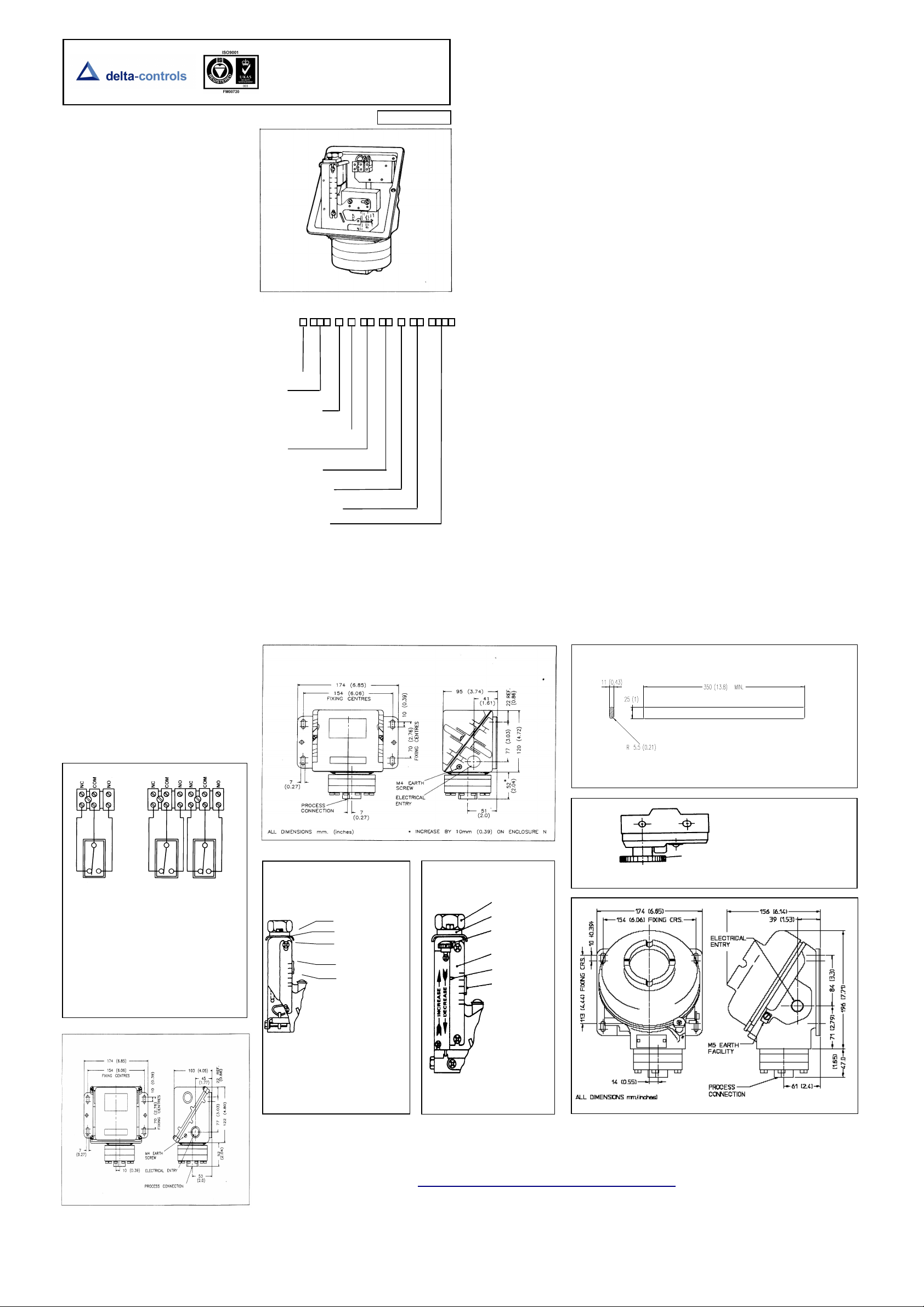
SPDT
REAR FRONT
SWITCH SWITCH
2 x SPDT
NC = NORMALLY CLOSED
COM = COMMON
NO = NORMALLY OPEN
FIG.1 shows the state of electrical
contacts at atmospheric pressure.
Note:- wiring from terminal block to
microswitch(es) is reversed to achieve
this state.
MODEL A 207
FIG. 5
INSTALLATION, OPERATING AND
MAINTENANCE INSTRUCTIONS FOR
DIAPHRAGM OPERATED ABSOLUTE
PRESSURE SWITCHES
(MODEL 207)
ISSUE E 09/09
PRODUCT CODE
ENCLOSURE
MODEL
ELECTRICAL ENTRY
MATERIAL OF WETTED PARTS
RANGE
SWITCHING OPTIONS
PROCESS CONNECTION
OPTIONS AND TREATMENTS
SPECIAL ENGINEERING
INSTALLATION
The instruments are designed to be mounted vertically with
the process connection underneath. They can be mounted
either direct to process or to a wall or panel using the
backplate provided. Select the mounting point so as to
avoid excessive shock, vibration or temperature
fluctuation. Instruments should be mounted to avoid
excessive heat transfer from the process lines or adjacent
plant.
If sudden changes of pressure (pulsations) are likely then
we recommend that snubbers are fitted between the
process line and the switch.
MODELS W, N 207
In the interest of development and improvement Delta Controls Ltd, reserve the right to amend without notice,
details contained in this publication. No legal liability will be accepted by Delta Controls Ltd, for any errors,
DELTA CONTROLS LIMITED, ISLAND FARM AVENUE, WEST MOLESEY, SURREY KT8 2UZ
T +44 (0) 208 939 3511 F +44 (0) 208 783 1163 E sales@delta-controls.com W www.delta-controls.com
Use a spanner to support the process connection when
fitting the instrument. When fitting the instrument lid make
sure gaskets or 'O' rings are in good condition and fitted
correctly.
WARNING: CHECK THE CONNECTION THREAD SIZE
AND SPECIFICATION ON THE UNIT TO AVOID MISMATCHING WITH THE PROCESS CONNECTION
ADAPTOR. SEE DIGIT 11 OF PRODUCT CODE.
WIRING (Fig 1)
Wire in accordance with local and National codes. Use
cables no larger than 2.5 mm sq. (14AWG). Deliver
electrical connection through a suitable cable gland which
will maintain the IP rating of the instrument. Insert bare
wires fully into the terminal block and tighten securely.
Keep wiring tails to a minimum and check that wires do not
interfere with the operating mechanism. Use the earthing
points provided.
CERTIFIED ENCLOSURES
All Series 200 Pressure Switches can be supplied with
BASEEFA certified enclosures to the following standards:
Zone 1 (Div. 1) IEC 79-1
BS 5501: Parts 1 and 5: EN50 014 and EN50 018
CENELEC. Codes "H" for aluminium and "K" for cast iron.
EExd IIC T6.
Code "M" Cast Iron Exd I T6 for mining.
Zone 2 (UK Only)
BS 4683: Part 3, Enclosure Code "N". ExN II T6
All the above mentioned enclosures are suitable for
outdoor use rated IP 66. Only operation, maintenance or
repair procedures either contained herein or approved by
Delta Controls may be used, to avoid rendering the
equipment unsafe in operation and/or nullifying the
Certification. NO MODIFICATIONS ARE PERMITTED.
Electrical Adaptors
Zone 1. Use only certified adaptors for Zone 1.
WARNING: IT IS A REQUIREMENT OF SAFETY THAT
AT LEAST 5 FULL THREADS ARE ENGAGED
BETWEEN THE ADAPTOR AND CONDUIT ENTRY.
TAKE CARE TO SELECT AND INSTALL ADAPTORS
THAT DO NOT REDUCE THE ENCLOSURE IP RATING.
Zone 2. Adaptors used must have equivalent IP rating to
the enclosure and be impact resistant to 7 N.m
References for Selection and Installation
BS 5345 Part 3 for Enclosure Codes H and K
BS 5345 Part 4 for all Enclosure Codes
(Intrinsic Safety)
BS 5345 Part 7 for Enclosure Code N
BS EN 60529 IP RATING (Ingress Protection)
MAINTENANCE
Inspections should be carried out at quarterly to yearly
intervals depending upon operating conditions.
Isolate the unit from process and power and remove the
lid. Check all terminals for tightness. Check that cable tails
are not fouled or chafed. Check for internal condensation.
Rectify as necessary.
It is recommended that instruments used to provide an
alarm are operated periodically to ensure they are
functioning correctly.
If further maintenance is required seek advice from DELTA
CONTROLS before attempting repair or replacement of
parts.
ADJUSTER KNOB
LOCKING PLATE
SECONDARY
ADJUSTER KNOB
SCALE PLATE
SECONDARY
INDICATOR
FIG. 5
FIG.7
omissions or amendments.
YOUR TRUSTED PARTNER IN PROCESS INSTRUMENTATION
needs to be hard chrome steel spanner grade.
ight use a flat bar (see below) or edge of ring spanner to open
CAUTION
Moving parts have been treated with a water repelling
lubricant before leaving the factory. Occasional
inspection and the application of a water repelling
lubricant is recommended to ensure moving parts
remain free under all conditions.
WARNING: DOES NOT APPLY TO OXYGEN SERVICE.
Zone 1 enclosures
Thread seal and contact surfaces must be lightly lubricated
using a non-setting non-corrosive grease compatible with
the Nitrile lid seal. Do not use copper bearing grease on
aluminium. Screw on lid hand tight making sure that
mating surfaces of the lid and enclosure are in contact. Retighten the lid lock screw.
WARNING: IT IS A SAFETY REQUIREMENT THAT AT
LEAST 5 FULL THREADS ARE ENGAGED WHEN THE
UNIT IS IN OPERATION. NEVER OPERATE THE UNIT
UNLESS THIS CONDITION IS MET. DO NOT USE
GREASES OR LUBRICANTS NOT COMPATIBLE WITH
THE ENVIRONMENT OR PROCESS.
Weatherproof enclosure (W and N)
If lid gasket is dried out or damaged, replace with new
greased gasket.
Stainless Steel Weatherproof Enclosure (A)
Check gasket. If damaged, replace.
OPERATION
Pressure switches are supplied calibrated against falling
pressure unless otherwise specified. Set Point adjustment
refers to falling pressure. Switching differential is the
difference between the set point and the operating value
on rising pressure. For opening details see Fig 2, 5 & 8.
Set Point Adjustment: Model 207 (Fig 4)
1. Isolate the instrument from process and power.
2. Remove the instrument lid.
3. Loosen the M3 hexagon head locking screw.
4. Rotate the 20 mm A/F hexagon head adjuster knob to
move the indicator along the calibrated scale. Rotate
clockwise to increase the set point and counter clockwise
to decrease the set point.
5. Retighten the locking screw taking care not to
overtighten.
6. Replace the instrument lid (See maintenance).
Set Point Adjustment: Model 207/2000 (fig 6)
1. Isolate the instrument from process and power.
2. Remove the instrument lid.
3. Rotate the knurled plastic wheel on the microswitch to
adjust the switch differential. Rotate clockwise to increase
the differential and counter clockwise to reduce the
differential.
4. Replace the instrument lid (see maintenance).
Set Point Adjustment: Model 207/3000 (Fig 7)
1. Isolate the instrument from process and power.
2. Remove the instrument lid.
3. Rotate the secondary adjuster knob to move the
secondary indicator along the ‘arrow’ scale. Rotate
clockwise to increase the differential and counterclockwise to decrease the differential.
4. Replace the instrument lid (see maintenance).
Note: For accurate setting, a suitable pressure gauge
must be used in conjunction with the above procedure. Do
not attempt to set the switch outside the scale limits.
Though the unit may be set anywhere within its operation
range, for optimum performance, it is good practice to
have a set point value between 25% and 75% of span.
ADJUST SW ITCHING
DIFFERENTIAL
FIG.3
FIG. 6
FIG. 8
Stock No: 002522/207
Registered Office Registered in England No 5369683
Page 2
–
Switch products with enclosure codes
be installed and used in accordance with the
main instructions and this addendum supplied with each product. Products rated
lower than 50V ac and 75 V dc are outside the scope of the LVD, and therefore, do
VD does not apply to products
with enclosure codes ‘H’, ‘K’, ‘R’, ‘M’, ‘N’ for use in hazardous areas. Switch products
with enclosure codes ‘H’, ‘K’, ‘R’, ‘M’, ‘N’, are covered by the Explosive Atmospheres
ndicate compliance with this
directive alone. The following directives do not apply to switch products
WIRING
h hole of 22 mm
blanked with a blind grommet. Discard the grommet and fit a suitable proprietary brass or
nylon M20 cable gland with thread length of 10 mm and locknut. Fit the nylon reducer provided
Alternately, the enclosure may be supplied from the factory with a threaded adaptor ready to
Alternatives:
i) a metal or nylon adaptor may be used to accommodate other sizes of gland eg NPT, or
° and
The user must make suitable local earthing arrangements, if required,
An earthing point is provided inside the enclosure. If this is disturbed in any way it must be
reassembled correctly to be an effective earth and prevent ingress. See diagram 4. When
ut first and ensure it is re tightened whenever the lid is
Enclosure ‘A’ is supplied with an M20 x 1.5 tapped hole. Use a
rnately the enclosure may be
supplied with a threaded adaptor fitted at the factory ready to accept the customer’s gland or
Bonding between the enclosure and gland / adaptor will be achieved
when bot
h parts are screwed together. An earthing point is provided inside the enclosure. If
this is disturbed in any way it must be reassembled correctly to be an effective earth and
All the
internal dead metal work is bonded to the enclosure earthing point. Due to requirements of
sealing, the process connection and back plates may be isolated from the earthing point. Do
nstead always use the earthing point provided. If
required, the process connection and back plates may be bonded locally. Never use the
process connection or inlet pipe for locally grounding welding equipment unless it is separately
Pollution degree
all products are suitable for use in pollution degree 3. For extreme
conditions where condensation may readily form, then sealed contacts should be used. See
These products are not suitable for electrical isolation. Always isolate
REDUCER
‘W’ CABLE GLAND ASSY
As the manufacturers of the apparatus listed, declare under our sole responsibility that the products listed
And thereby conforms to the requirements of the Low
Low Voltage Directive (LVD)
‘W’ and ‘A’ supplied CE-marked must
not require CE-marking under this directive. The L
Directive ATEX – 94/9/EC and when CE-marked will i
manufactured by Delta Controls:
Electromagnetic Compatibility EMC – 2004/108/EC
Machinery Safety Directive MSD – 2006/42/EC
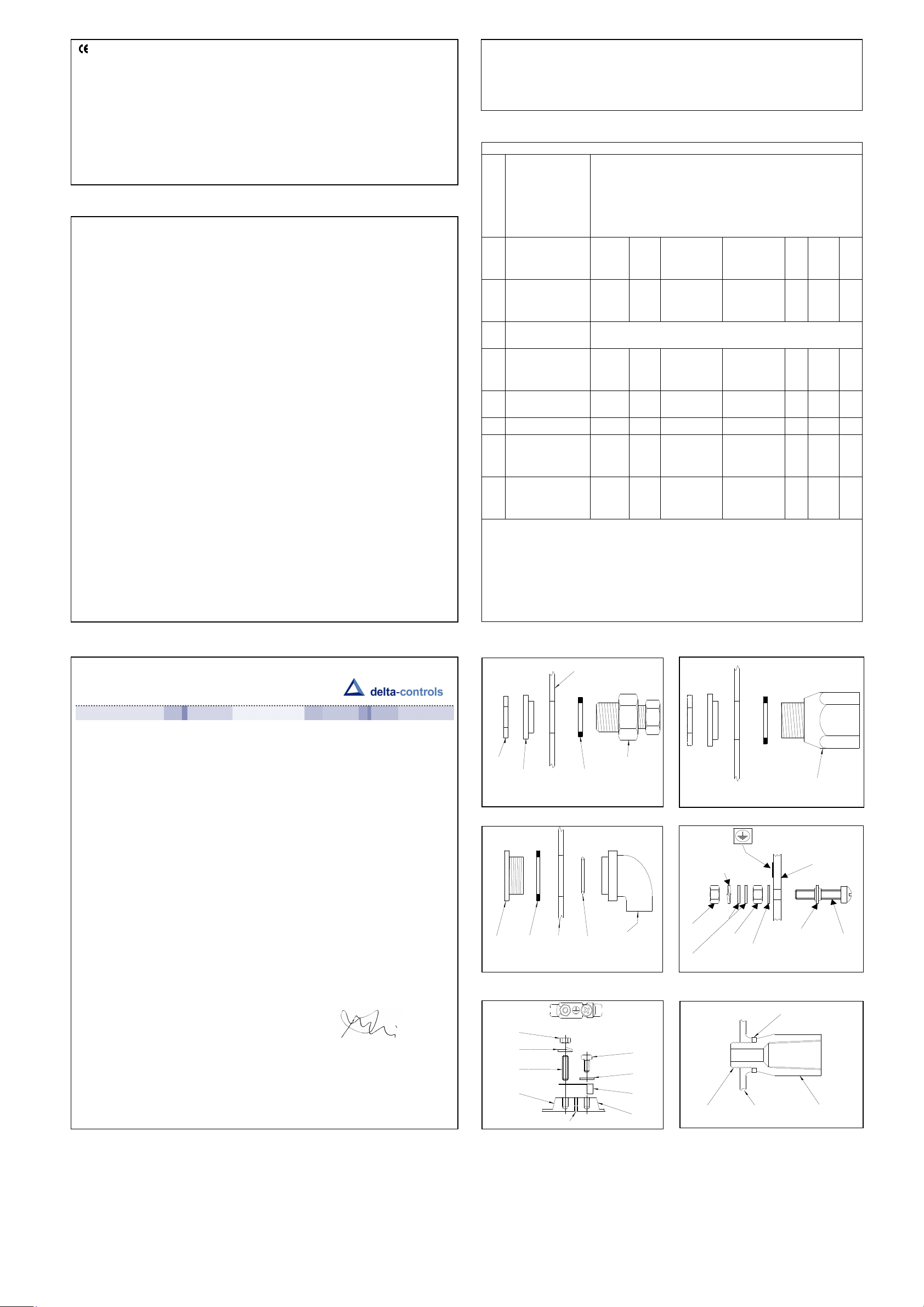
ENCLOSURE ‘W’
Cable Glands and adaptors – If enclosure ‘W’ is supplied with a throug
to the inside and a fibre washer to the outside. See diagram 1.
accept the customer’s gland or conduit system.
conduit system. See diagram 2.
ii) an elbow kit may be supplied to enable the entry to be rotated axially through 90
radially through 360°. See diagram 3.
Earthing / grounding –
to ensure that metal glands are earthed.
removing the lid slacken the M4 n
replaced. See diagram 4.1.
ENCLOSURE ‘A’
Cable Glands and adaptors –
suitable stainless steel cable gland and sealing washer. Alte
conduit system. See diagram 5.
Earthing / grounding –
prevent ingress. See diagram 4.
EARTHING / GROUNDING OF PROCESS CONNECTION AND BACK PLATES –
not, therefore, rely on either for earthing, i
earth bonded.
Declaration of Conformity
We: Delta Controls Ltd
Island Farm Avenue
West Molesey
Surrey, UK
KT8 2UZ
below:
Pressure, Pressure Difference, Temperature & Flow switches series “W” or “A”:
201, 202, 203, 281, 204, 207, 208, 209, 231, 232, 233, 234, S21, S22, S24, GR2, GR4, VM2, VM4.
301, 303, 304, 381, 384, 306, 386, 310, 316, S31, S34, GR3, GR6.
721, 731, 771, 722, 732, 772, 723, 733, 773, 781, 734, 774, 741, 742, 743, 744, S71, GR7.
131.
To which this declaration relates are in conformity with the following relevant standards or parts thereof:
EN 60947-1 :1992 Low voltage switch gear and control-gear-general rules.
EN 60947-5-1:1992 Low voltage switch gear and control-gear-control circuit devices and switching
elements.
EN 60529: 1991 Specification for classification of degrees of protection provided by enclosures.
EN 60950:1992 Safety of information technology equipment including electrical business equipment:
section 2.5.
BS 6134:1991 Specification for pressure and vacuum switches.
………………….
R. Harrison
Managing Director
Original dated 22nd June 2000
Rev. B dated 12
th
August 2009
2006/95/AC.
Voltage Directive 73/23/EC amended by 93/68/EEC.
Signed:
Table A codes 08/09, 0G/0H, H2/H3/H6.
Electrical isolation –
circuit separately to carry out any electrical work.
TABLE A – MICROSWITCH RATINGS
MICROSWITCH
(RESISTIVE)
*SEE NOTE
SWITCH CODE
5A @ 110 / 250 VAC
00
0.8kV 250V
&
01
5A @ 110 / 250 VAC
02
0.8kV 250V
&
2A @ 30 VDC
03
1A @ 125 VAC
04
N/A
&
05 *100mA @ 30 VDC
*5A @ 110/250VAC
0P
0.5kV 250V
&
2A @ 30 VDC
0Q
*1A @ 30VAC
0G
0.5kV 125V
&
0H & 30 VDC
0C 5A @ 110 / 250 VAC 0.8kV 250V
5A @ 110 / 250 VAC
0D
0.8kV 250V
2A @ 30 VDC
H2
5A @ 110 / 250 VAC
&
H3
0.5kV 250V
&
2A @ 30 VDC
H6
UL / CSA
RATING
–
IEC 947-5-1 / EN 60947-5-1 RATING
RATING
Uimp
Ui
(IeIUe)
0.6/0.3A @
120/240 VAC
0.22/0.1A @
125/250 VDC
0.6/0.3A @
120/240 VAC
0.22/0.1A @
125/250 VDC
0.6/0.3A @
120/240 VAC
0.22/0.1A @
125/250 VDC
0.3A @ 120
VAC
0.6/0.3A @
120/240 VAC
0.6/0.3A @
120/240 VAC
0.22/0.1A @
125/250 VDC
0.6/0.3A @
120/240 VAC
0.22/0.1A @
125/250 VDC
Designation
&
Utilisation
Category
AC 14 / D300 AC 432 72
DC 13 / R300 DC 28 28
AC 14 / D300 AC 432 72
DC 13 / R300 DC 28 28
AC 14 / D300 AC 432 72
DC 13 / R300 DC 28 28
AC 14 / E150 AC 216 36
AC 14 / D300 AC 432 72
AC 14 / D300 AC 432 72
DC 13 / R300 DC 28 28
AC 14 / D300 AC 432 72
DC 13 / R300 DC 28 28
The electrical rating is dependent on the microswitch fitted to the instrument. The
electrical rating is defined by each approval that the microswitch complies with and
is shown on the product nameplate, ie UL / CSA, or IEC. It should be noted that the
switch must be used within the electrical rating specified from the approval you
require. Table A lists the actual IEC ratings against the Designation & Utilisation
Category marked on the nameplate. In the absence of any verification by UL / CSA
the microswitch *manufacturer’s rating is specified in bold italics. If in doubt, seek
guidance from factory.
DIAG 1
LOCKNUT
NYLON 22/20
DIAG 3
GLAND
FIBRE
SCREW
WASHER
DIAG 4.1
M4 NUT
M4 SINGL E
COIL WAS HER
M4 STU D
LID
EARTH STRAP
ENCLOSURE WALL
FIBRE WASHER
ENCLOSURE
WALL
O RING
SEAL
ELBOW ASSY
GASKET
PROPRIETARY
GLAND
½" NPT Pg 13.5
M20 X 1.5 ¾ ET
M4 SCR EW
M4 PLAIN
WASHER
EARTH
STRAP
BASE
DIAG 2
‘W’ ADAPTOR ASSY
EARTH L A B E L
SING LE
COIL
W AS H E R
NUT
PLA IN
W A S H E RS
D IA G 5
NUT
STAR W ASHER
E N C L O S U R EM 2 0 x 1 .5
CABLE GLAND /
CONDUIT ADAPTOR
DIAG 4
ENC LOS U R E W ALL
(E X T E R IOR)
BOND E D SEAL
EAR T HIN G ASS Y
F IB R E W A S H E R
‘A ’ A D A P T O R
VA
Make
SCREW
A D A P T O R
Break
 Loading...