

Page 1
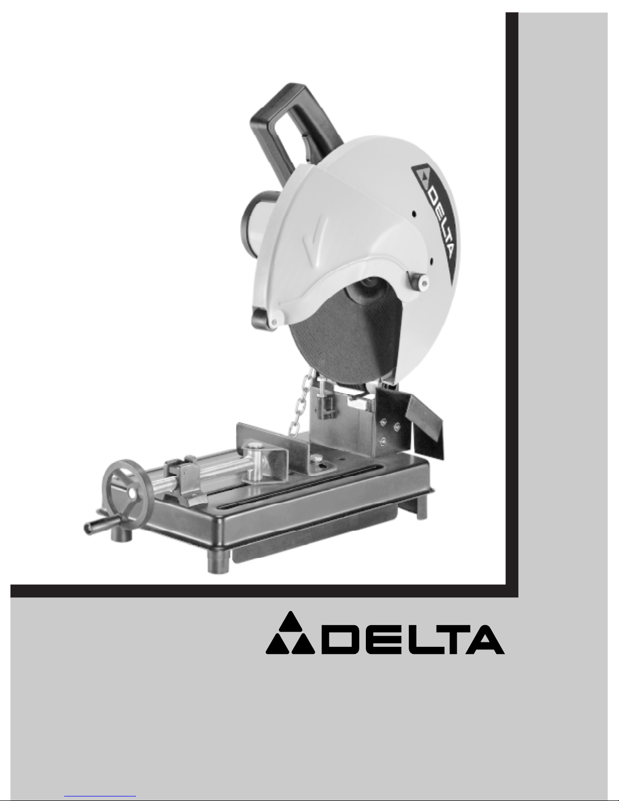
14” Abrasive Cut-Off Saw
(Model 20-142C)
INSTRUCTION MANUAL
Dated 11-10-02
To learn more about DELTA MACHINERY
visit our website at: www.deltamachinery.com.
For Parts, Service, Warranty or other Assistance,
please call 1-800-463-3582.
Copyright © 2002 Delta Machinery
Part No. 1236490
A Pentair Company
1
Page 2

2
Page 3

TABLE OF CONTENTS
SAFETY INSTRUCTIONS................................................. 4,5
ELECTRICAL CONNECTIONS
Power Source....................................................................6
Extension Cords ................................................................6
Grounding Instructions ......................................................6
UNPACKING MACHINE ............................................7
Moving Cutting Head To The Up Position..........................7
OPERATING CONTROL AND ADJUSTMENTS
Starting And Stopping Saw............................................... 8
Vise................................................................................... 8
Angle Cutting .....................................................................8
Adjusting Downward Travel Of Abrasive Wheel ................9
Carrying Handle................................................................ 9
Cutting Operation .............................................................10
MAINTENANCE
Changing The Abrasive Wheel.........................................11
ACCESSORIES, PARTS,
SERVICE, AND WARRANTY
.........................................12
3
Page 4

SAFETY RULES
As with all machinery there are certain hazards involved
with operation and use of this machine. Using the
machine with respect and caution will considerably
lessen the possibility of personal injury. However, if
normal safety precautions are overlooked or ignored,
personal injury to the operator may result.
This machine was designed for certain applications only.
DELTA MACHINERY strongly recommends that this
machine NOT be modified and/or used for any
application other than for which it was designed. If you
WARNING: FAILURE TO FOLLOW THESE RULES MAY RESULT IN SERIOUS PERSONAL INJURY.
1. For your own safety, read instruction manual before
operating the tool. Learn the tool’s application and limitations
as well as the specific hazards peculiar to it.
2. Keep guards in place and in working order.
3. Always wear eye protection. Wear safety glasses.
Everyday eyeglasses only have impact resistant lenses; they
are not safety glasses. Also use face or dust mask if cutting
operation is dusty. These safety glasses must conform to ANSI
Z87.1 requirements. Note: Approved glasses have Z87 printed
or stamped on them.
4. Remove adjusting keys and wrenches. Form a habit of
checking to see that keys and adjusting wrenches are removed
from tool before turning it “ON”.
5. Keep work area clean. Cluttered areas and benches invite
accidents.
6. Don’t use in dangerous environment. Don’t use power
tools in damp or wet locations, or expose them to rain. Keep
work area well-lighted.
7. Keep children and visitors away. All children and visitors
should be kept a safe distance from work area.
8. Make workshop childproof – with padlocks, master
switches, or by removing starter keys.
9. Don’t force tool. It will do the job better and safer at the rate
for which it was designed.
10. Use the right tool. Don’t force tool or attachment to do a
job for which it was not designed.
11. Wear proper apparel. No loose clothing, gloves, neckties,
rings, bracelets, or other jewelry to get caught in moving parts.
Nonslip footwear is recommended. Wear protective hair
covering to contain long hair.
12. Secure work. Use clamps or a vise to hold work when
practical. It’s safer than using your hand and frees both hands
to operate tool.
13. Don’t overreach. Keep proper footing and balance at all
times.
14. Maintain tools in top condition. Keep tools sharp and
clean for best and safest performance. Follow instructions for
lubricating and changing accessories.
15. Disconnect tools before servicing and when changing
accessories such as blades, bits, cutters, etc.
16. Use recommended accessories. The use of accessories
and attachments not recommended by Delta may cause
hazards or risk of injury to persons.
have any questions relative to a particular application,
DO NOT use the machine until you have first contacted
Delta to determine if it can or should be performed on the
product.
Delta Machinery
Technical Service Manager
505 Southgate Drive
Guelph, ONTARIO N1H 6M7
17. Reduce the risk of unintentional starting. Make sure
switch is in “OFF” position before plugging in power cord. In the
event of a power failure, move switch to the “OFF” position.
18. Never stand on tool. Serious injury could occur if the tool is
tipped or if the cutting tool is accidentally contacted.
19. Check damaged parts. Before further use of the tool, a
guard or other part that is damaged should be carefully checked
to ensure that it will operate properly and perform its intended
function - check for alignment of moving parts, binding of
moving parts, breakage of parts, mounting, and any other
conditions that may affect its operation. A guard or other part
that is damaged should be properly repaired or replaced.
20. Direction of feed. Feed work into a blade or cutter against
the direction of rotation of the blade or cutter only.
21. Never leave tool running unattended. Turn power off.
Don’t leave tool until it comes to a complete stop.
22. Stay alert, watch what you are doing, and use common
sense when operating a power tool. Do not use tool while
tired or under the influence of drugs, alcohol, or
medication. A moment of inattentioin while operating power
tools may result in serious personal injury.
23. Make sure tool is disconnected from power supply while
motor is being mounted, connected or reconnected.
24. The dust generated by certain woods and wood products
can be injurious to your health. Always operate machinery in
well ventilated areas and provide for proper dust removal. Use
wood dust collection systems whenever possible.
25. WARNING: Some dust created by power sanding,
sawing, grinding, drilling, and other construction activities
contains chemicals known to cause cancer, birth defects or
other reproductive harm. Some examples of these chemicals
are:
• Lead from lead-base paints
• Crystalline silica from bricks and cement and other masonry
products.
• Arsenic and chromium from chemically-treated lumber.
Your risk from these exposures varies, depending on how often
you do this type of work. To reduce your exposure to these
chemicals: work in a well ventilated area, and work with
approved safety equipment, such as those dust masks that are
specially designed to filter out microscopic particles.
SAVE THESE INSTRUCTIONS
Refer to them often and use them to instruct others.
4
Page 5

ADDITIONAL SAFETY RULES
FOR ABRASIVE CUT-OFF SAWS
WARNING: DO NOT OPERATE YOUR ABRASIVE CUT-OFF SAW UNTIL IT IS COMPLETEL Y
ASSEMBLED AND INST ALLED ACCORDING TO THE INSTRUCTIONS.
1. If you are not thoroughly familiar with the operation of
abrasive cut-off saws, obtain advice from your supervisor,
instructor or other qualified person.
2. WEAR safety goggles, face shield, respirator, body
apron, headcovering, safety shoes, long tight-fitting
sleeves, and gloves.
3. Use only recommended reinforced abrasive wheels
with blotters.
4. Tighten arbor screw and all clamps before operating.
5. Make sure spindle lock is disengaged before
operating.
6. Always keep guards in place and working properly .
7. Keep hands clear of cut-off wheel.
8. Secure workpiece properly. Work should be straight
and firmly clamped to avoid possible movement and
pinching as the cut nears completion.
9. Never cut anything freehand.
10. Never reach behind or beneath the cut-off wheel.
11. Make sure the wheel has come to a complete stop
before removing or securing workpiece or changing
workpiece angle.
12. Make sure the inside surfaces of the wheel flanges
(as well as the sides of the wheel) are free from any
foreign matter.
13. When mounting the wheel, care should be taken to
tighten the arbor screw only enough to hold the wheel
firmly and to prevent wheel slippage. Excessive tightening
may result in damaging the wheel and springing the
wheel flanges.
14. Use only abrasive wheels rated at 3900 RPM or
higher.
15. Always check the wheel for cracks or other damage
before operation. Replace cracked or damaged wheel
immediately.
16. Use only wheel flanges specified for your machine.
17. Make sure abrasive wheel is not contacting
workpiece before switch is turned on.
18. Allow the motor to come up to full speed before
starting cut.
19. After turning machine on, lower wheel slightly until it
comes in contact with the workpiece and then draw wheel
firmly through the cut. Do not allow the wheel to chatter
and jump as this may cause the wheel to wear out of
round, resulting in poor cutting and possible broken
wheels.
20. Any material is easily cut when placed in position for
the wheel to cut with the least arc of contact.
21. The number of cuts per wheel, as well as the quality
of cut, may vary considerably with the cutting time. Fast
cuts cause the wheel to wear more rapidly but also help
to reduce discoloration and burr. this is especially
noticeable when cutting light gage tubing. When coming
through the bottom wall, with the longer arc of contact, do
not slow-up but give a vigorous pull. This keeps the metal
from overheating and dragging off in a heavy burr.
22. Use the wheel guard at all times.
23. Never operate the machine in an area with flammable
liquids or gases.
24. To avoid electrical shock, do not use under damp
conditions or expose to rain.
25. This tool is designed for ferrous metals only. Do not
attempt to cut wood, masonry, aluminum, or magnesium
with this tool.
26. After installing a new wheel, never start the tool with
a person in line with the wheel. Always run the tool for
approximately one minute before cutting. If the wheel has
an undetected crack or flaw, it could burst in less than
one minute.
27. Shut off power before servicing or adjusting tool.
28. Should any part of your machine be missing, damaged, fail in any way, or any electrical component fail to
perform properly, shut off switch and remove plug from
power supply outlet. Replace missing, damaged, or failed
parts before resuming operation.
5
Page 6

ELECTRICAL CONNECTIONS
Power Source
A separate electrical circuit should be used for your tool. This circuit should not be less than #12
wire and should be protected with a 20 amp fuse. Before connecting the motor to the power line,
make sure the switch is in the “OFF” position and be sure the electric current is of the same characteristics as indicated on the tool. All line connections should make good contact. Running on low
voltage will damage the motor.
Extension Cords
Figure 1
Make sure your extension cord is in good condition and
is a 3-wire extension cord which has a 3-prong grounding
type plug and matching receptacle which will accept the
tool’s plug. When using an extension cord, be sure to
use one heavy enough to carry the current of the tool.
An undersized cord will cause a drop in line voltage,
resulting in loss of power and overheating. Extension
cords should be no longer than 50 ft.
WARNING: DO NOT EXPOSE THE TOOL TO RAIN OR OPERATE IN DAMP LOCATIONS.
Fig. 1
Grounding Instructions
WARNING: THIS TOOL MUST BE GROUNDED WHILE IN USE TO PROTECT THE
OPERATOR FROM ELECTRIC SHOCK.
All grounded, cord-connected tools:
In the event of a malfunction or breakdown, grounding provides a path of least resistance for electric
shock. This tool is equipped with an electric cord having an equipment-grounding conductor and a
grounding plug. The plug must be plugged into a matching outlet that is properly installed and
grounded in accordance with all local codes and ordinances. Do not modify the plug provided - if it
will not fit the outlet, have the proper outlet installed by a qualified electrician.
Improper connection of the equipment-grounding conductor can result in risk of electric shock. The
conductor with insulation having an outer surface that is green with or without yellow stripes is the
equipment-grounding conductor. If repair or replacement of the electric cord or plug is necessary, do
not connect the equipment grounding conductor to a live terminal. Check with a qualified electrician
or service personnel if the grounding instructions are not completely understood, or if in doubt as to
whether the tool is properly grounded.
Figure 2
Grounded, cord-connected tools intended for
use on a supply circuit having a nominal rating
less than 150 volts will have a grounding plug
similar to illustration.
WARNING:
IN ALL CASES, MAKE SURE THE RECEPTACLE IN QUESTION IS PROPERLY GROUNDED.
Fig. 2
6
Page 7

UNPACKING MACHINE
Figure 3
Your new 14” Abrasive Cut-Off Saw is shipped
complete in one carton. Carefully unpack the
saw and all loose items from the shipping container.
Moving Cutting Head
To The Up Postion
Figure 4
For shipping purposes, the cutting head (A) has
been clamped in the Down position (against a
foam packing block) by means of the holddown
chain (B).
Figure 5
To move the cutting head (A) to the Up position,
simply unhook the chain (B) from the handle
housing.
Fig. 3
Fig. 4
Fig. 5
7
Page 8

OPERATING CONTROLS
AND ADJUSTMENTS
Starting And Stopping Saw
Figure 6
Your 14” Abrasive Cut-Off Saw is equipped with
a two stage safety on/off switch. To turn the saw
ON, slide safety lock (A) to the rear, then depress switch trigger (B). To turn the saw OFF,
release switch trigger (B).
Vise
Clamping the workpiece can be accomplished
quickly and easily.
Figure 7
Lift half-nut (A) off screw (B). Pull screw far
enough away from rear vise clamp (C) to
accomodate workpiece.
NOTE: With the half-nut raised, the screw can
be easily slid in or out.
Figure 8
Fig. 6
Fig. 7
Slide in screw (A) until front vise clamp (B)
contacts workpiece. Flip half-nut (C) over to
engage screw (A). Tighten screw handle (D) to
securely clamp workpiece in the vise.
Angle Cutting
Figure 9
Using supplied wrench, loosen two screws (A)
and rotate rear vise clamp (B) to the desired
angle. Tighten the two screws. The front vise
clamp (C) pivots on its post and will self-align
with the workpiece.
Fig. 8
8
Fig. 9
Page 9

Figure 10
This view illustrates a typical angle cutting
operation.
Adjusting Downward Travel
Of Abrasive Wheel
Figure 11
A stop screw (A) is provided to limit the downward travel of the abrasive wheel. This adjustment is made by loosening lock nut (B) and
turning stop screw in or out as needed. Then
tighten lock nut
Fig. 10
Figure 12
This view illustrates the stop plate (A) contacting stop screw (B).
NOTE: As the diameter of the abrasive wheel
decreases (due to wear), the downward travel
can be increased.
Carrying Handle
Figure 13
A carrying handle (A) is provided for ease of
transportation. When transporting the machine,
the cutting head should be locked in the down
position using the holddown chain (B).
Fig. 11
Fig. 12
9
Fig. 13
Page 10

Cutting Operation
Figure 14
Clamp the workpiece securely in the vise. Turn
on the saw and allow the motor to come up to
full speed before touching the workpiece with
the wheel.
Figure 15
Lower the wheel (A) lightly until it makes contact
with the workpiece. Continue to firmly push
down on the handle while the cut is being made.
NOTE: Do not allow the wheel to chatter and
jump as this can cause the wheel to wear out of
round, resulting in poor quality of cut and, possibly,
broken
wheels.
Fig. 14
Figure 16
Do not slow up when coming through the
bottom of the cut. This keeps the metal from
overheating and dragging off in a heavy burr.
Figure 17
This view shows a finished cut-off operation.
NOTE: The number of cuts per wheel, as well as
the quality of cut, will vary with the speed and/or
type of material. Fast cuts cause the wheel to
wear more rapidly, but also help to reduce
discoloration and burr.
Fig. 15
Fig. 16
10
Fig. 17
Page 11

MAINTENANCE
Changing The Abrasive Wheel
DISCONNECT TOOL FROM POWER SOURCE
Figure 18
Rotate the front wheel guard (A) to the up
position.
Figure 19
Press arbor lock (A) toward wheel housing while
rotating wheel (B) by hand until the arbor lock
engages.
Fig. 18
Figure 20
Using the supplied wrench, loosen arbor screw
(A) by turning it counterclockwise. Remove
arbor screw, washer (B), outside wheel flange
(C), and wheel (D).
NOTE: Do not remove inside wheel flange.
Clean the inside surfaces of both the inside and
outside wheel flanges.
Install new wheel and replace outside wheel
flange, washer, and arbor screw. Tighten arbor
screw clockwise.
IMPORTANT: Use only reinforced abrasive
wheels with blotters and tighten arbor screw
only enough to hold wheel firmly and prevent
slippage. Excessive tightening may result in
damage.
Rotate front wheel guard to down position and
disengage spindle lock before starting tool.
Fig. 19
Fig. 20
11
Page 12

ACCESSORIES
A complete line of accessories is available form your Delta Supplier, Porter-Cable • Delta
Factory Service Centers, and Delta Authorized Service Stations. Please visit our Web Site
www.deltamachinery.com for a catalog or for the name of your nearest supplier.
WARNING: Since accessories other than those offered by Delta have not been tested
with this product, use of such accessories could be hazardous.
For safest operation, only Delta recommended accessories should be used with
this product.
PARTS, SERVICE, AND WARRANTY ASSISTANCE
All Delta Machines and accessories are manufactured to high quality standards and are
serviced by a network of Porter-Cable • Delta Factory Service Centers and Delta Authorized
Service Stations. To obtain additional information regarding your Delta quality product or to
obtain accessories, parts, service, warranty assistance, or the location of the nearest
service outlet, please call 1-800-463-3582.
Two Year Limited Warranty
Delta will repair or replace, at its expense and at its option, any Delta machine,
machine part, or machine accessory which in normal use has proven to be
defective in workmanship or material, provided that the customer returns the
product prepaid to a Delta factory service center or authorized service station
with proof of purchase of the product within two years and provides Delta with
reasonable opportunity to verify the alleged defect by inspection. Delta may
require that electric motors be returned prepaid to a motor manufacturer’s
authorized station for inspection and repair or replacement. Delta will not be
responsible for any asserted defect which has resulted from normal wear,
misuse, abuse or repair or alteration made or specifically authorized by anyone
other than an authorized Delta Service facility or representative. Under no
circumstances will Delta be liable for incidental or consequential damages
resulting from defective products. This warranty is Delta’s sole warranty and
sets forth the customer’s exclusive remedy, with respect to defective products;
all other warranties, express or implied, whether of merchantability, fitness for
purpose, or otherwise, are expressly disclaimed by Delta.
12
 Loading...