

Page 1
1
Operating
Manual
www.DelphiGlass.com 800-248-2048
3380 E. Jolly Road Lansing, MI 48910
Delphi has teamed up with
Jen-Ken Kilns and Orton to
produce the most user
friendly, versatile kiln for
glass artists ever.
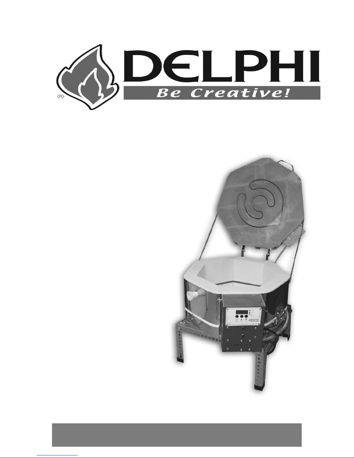
EZ-Pro 15-6 Kiln
Page 2

2
This manual contains instructions on the operation of the kiln
and Delphi EZ-PRO controller as well as a discussion of
general fusing procedures. It is not intended to replace a
fusing class or comprehensive fusing instructional media.
Revised: October 22, 2007
Page 3

3
Table of Contents
Safety First ................................................................................................. 5
About Your Kiln .......................................................................................... 6
Introduction ..................................................................................... 6
Kiln Accessories .............................................................................. 8
Kiln Specifications ........................................................................... 9
Choosing a Location for Your Kiln ................................................. 10
Setting up Your Kiln ...................................................................... 11
Quick Start Guide or
Enough Reading – I want to melt something! ................................ 12
EZ-Pro Controller……………………………………………………….13
Audible Alarm ..................................................................... 13
Temperature Display Preference ........................................ 14
Temperature measurement ................................................ 14
Temperature Control .......................................................... 14
Firing Program Terminology ............................................... 14
Program Modes .................................................................. 16
Changing Program Modes ....................................... 16
Selecting the Firing Schedule or Programs ............. 16
90 COE program mode ...................................................... 17
96 COE program mode ...................................................... 18
Bead program mode ........................................................... 19
Metal Clay program mode .................................................. 20
User program mode ............................................................ 21
Other program notes .......................................................... 23
Delay Start Option ................................................... 23
Thermocouple offset option ..................................... 24
Program Review ................................................................. 24
Options Menu ..................................................................... 25
Skip Step ............................................................................ 25
Add Hold Time .................................................................... 25
Changing Heating/Cooling Temperatures .......................... 25
Threshold alarm ................................................................. 25
Flow diagram for options menu .......................................... 26
Power fail recovery ............................................................. 26
Status Display Codes ......................................................... 27
Alarm Display Codes .......................................................... 27
Wiring Diagram ................................................................... 29
Beginner Instructions ............................................................................... 30
Fused Glass Project ................................ ...................................... 30
Working with tested compatible glass ................................. 30
How to prepare your glass project ...................................... 30
Firing your glass project ..................................................... 30
Page 4

4
Firing Process .................................................................... 31
Firing Stages ...................................................................... 32
Firing 90 COE Glass for Beginners ............................................... 34
Firing 96 COE Glass for Beginners ............................................... 36
Batch Annealing Glass Beads ....................................................... 38
Firing Your Metal Clay Projects ..................................................... 40
Intermediate Mode ........................................................................ 42
Keeping a log ..................................................................... 42
Changing pre-programmed firing programs ........................ 42
Professional Mode ........................................................................ 43
Firing Programs ............................................................. 45-54
Controller Warranty ....................................................................... 55
Page 5

5
SAFETY FIRST
Read and understand all operating instructions before operating your kiln.
SAFETY PRECAUTIONS: Kilns are as safe as any other electrical appliance when
used under normal and proper operating conditions. All safety precautions throughout
this manual should be observed.
o Use common sense while installing and using this kiln.
o Do not install kiln closer than 12" from any surface, or closer than 18” from a
combustible surface. Remove all potentially combustible materials from the kiln
area
o Make sure all electrical specifications are followed. Use correct voltage, wire
size and circuit breaker. Make sure all connections are tight. Avoid using
aluminum wire. Always use the proper grounded receptacle. A qualified
electrician or service person should be used for all electrical service or repairs.
o Install in covered, walled in, well-ventilated area. Do not allow your kiln to get
wet. Fumes from the ware should be vented to the outside. Never use your kiln
outside! Avoid moisture.
o Always keep children and unsupervised personnel away. Surface will get hot and
a burn could result.
o Fire glass only to the manufacturers recommended firing temperature. Improper
fire temperatures could result in damage to your kiln. Do not operate kiln over the
maximum temperature rating of 1700oF.
o Replace any worn or defective parts with ONLY genuine Jen-Ken Kiln
replacement parts.
o Unplug the kiln before servicing or vacuuming.
o Do not drop or slam the lid shut.
o Let the kiln cool to room temperature before opening the lid.
o NOTE: If you are in doubt about anything, call Delphi Glass 800.248.2048 or
Jen-Ken Kilns during regular business hours at 800.329.KILN.
Page 6
6
ABOUT YOUR KILN
Introduction
The Delphi EZ- Pro Kiln 15-6 is a professional quality Jen-Ken kiln.
The controller has been designed and programmed to Delphi specifications by
Orton Ceramics.
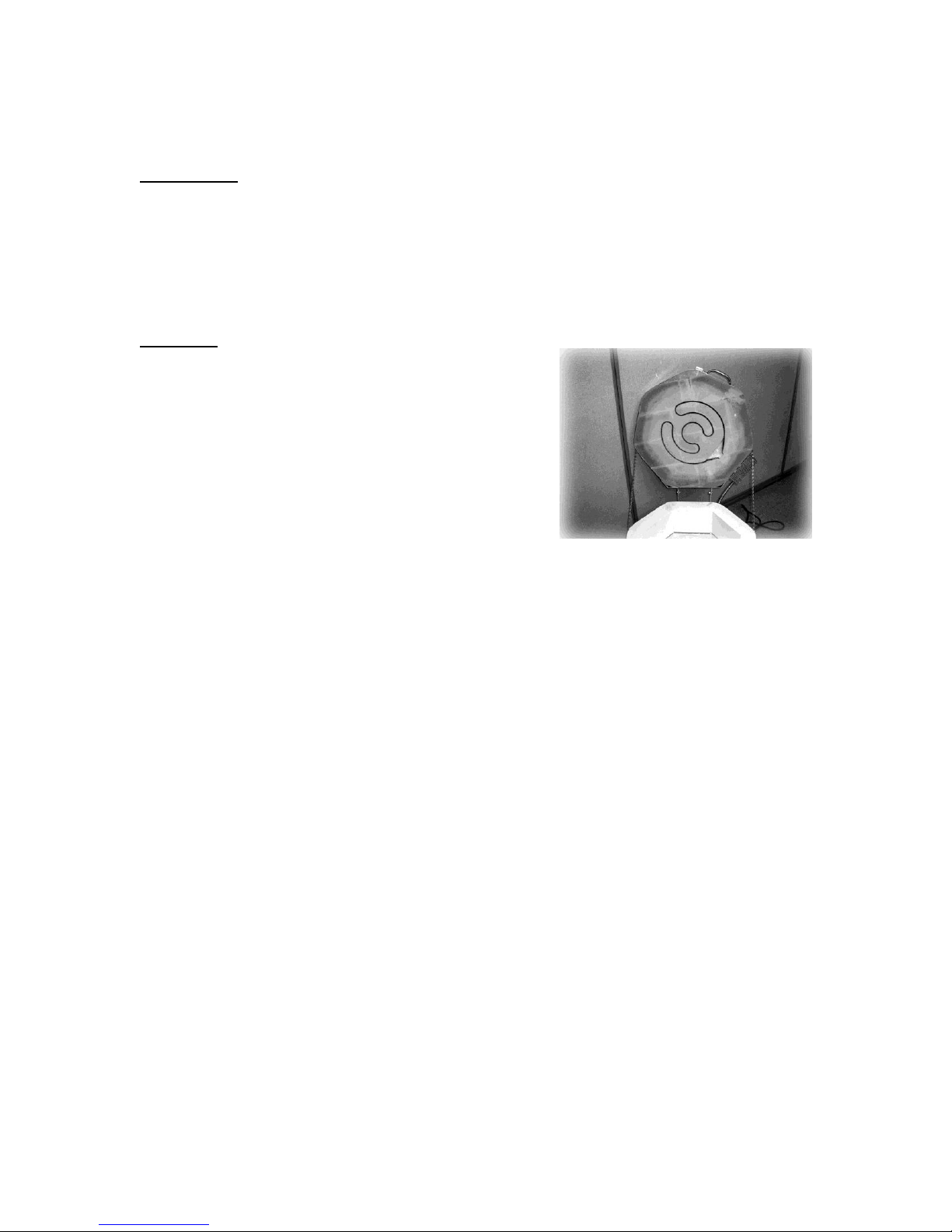
Elements
Elements are the coils of wire that produce heat
inside the kiln. They are made from a high quality,
high-temperature wire. During the firing, they
become very soft and when cool become brittle. Life
expectancy of the elements will depend on the
number of firings and the firing temperatures. At
lower temperatures, the elements will last longer than
firing at higher temperatures. Care should be taken
to make sure that no foreign matter (such as glass,
glazes, clay or kiln wash) come in contact with the elements. This will greatly reduce
their life expectancy. Regular vacuuming of the kiln lid, bottom and the element grooves
is recommended.
In a digital kiln, the coils as a group turn on and off during firing. You will hear the
clicking of the relays. It will click more if a slow rate of rise in temperature is used and
less if the kiln is told to fire quickly. Your EZ-PRO kiln has separate relays for the top
and side elements to increase the life of the relays.
Glass kilns usually have coils in the lid and side walls. The lid coils do most of the work
in the kiln and get the hottest. Side coils are supplemental heat and help bring the kiln to
temperature. It takes the side and the lid coils to bring the kiln to fusing temperatures.
SAFETY FIRST: In a digital kiln, if a relay fails, the section that the relay controls might
not heat up, or could stay on continuously. If this happens, turn off the kiln at the
breaker and unplug. At this point, you will need to replace the relay. Call Jen-Ken Kiln
Company for assistance.
The EZ-Pro Kiln has multiple relays so that if one relay fails the kiln cannot heat too high
in temperature.
Page 7

7
Kiln Brick
All Jen-Ken kilns are made of hand selected 2400°F
refractory brick. The brick is strong as a whole and
has a very long life. The brick can chip easily and
care should be taken to avoid bumps while loading
and unloading shelves. Frequently vacuum the brick
lid, the grooves that the elements are in and the
bottom of the kiln. This will remove the dust, sand
and loose kiln wash from the kiln.
Kiln Jacket
Your kiln is encased in a stainless steel jacket and is also equipped with handles for
easy moving. Due to the high temperatures, discoloration may appear on
the stainless jacket. A good metal polish will remove this discoloration.
Accessories
Shelves: Shelves help you make the most of the inside for your kiln. Shelves are sized
a few inches smaller than the inside diameter of the kiln so that they can be placed in
and out of the kiln more easily. They are made of refractory material so that they should
be handled carefully. Should a crack appear in a shelf, break the shelf along the crack
and use it as two separate pieces. A good coat of kiln wash should ALWAYS be
maintained on top of the shelves. Store shelves upright on edge, leaning on a sturdy
structure, not flat on their sides. Shelves stacked flat can put too much pressure on the
bottom shelf and cause it to stress and crack. Store shelves that are not in the kiln on
edge.
Posts: Posts are also made from refractory material
and should be handled carefully. Post sizes range in
heights from ½” to 14”. They are used to support the
shelves in your kiln at different levels depending
upon the height of the pieces you are firing. Usually,
three posts allow you to level the shelf more easily
(although some fusers prefer four).
Page 8
8
RECOMMENDED
KILN ACCESSORIES
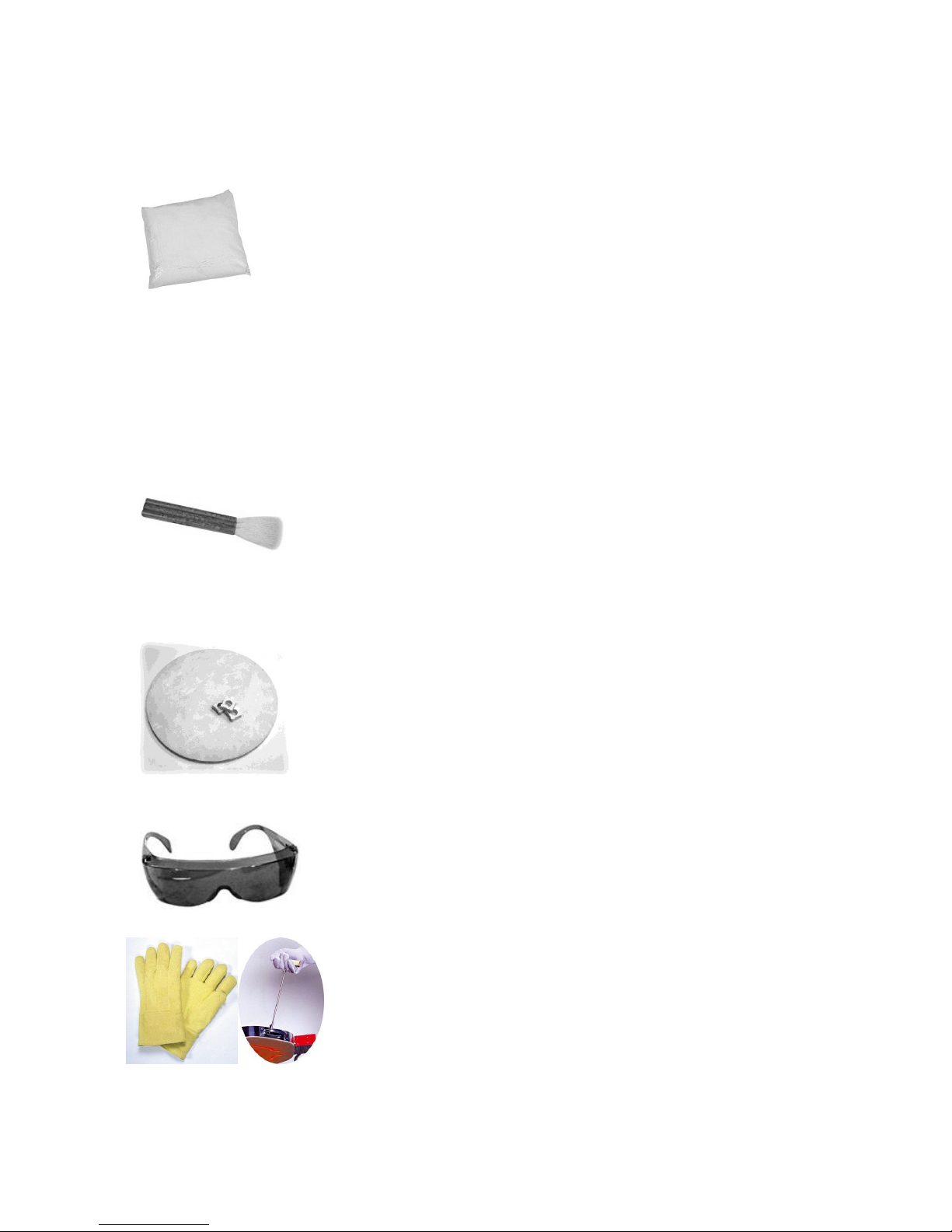
Glass Kiln Wash is a mixture of very fine minerals that will not fuse or
melt together at high temperatures and act as a barrier between the kiln shelf or mold
and glass. It is used to prevent glass from sticking to the firebrick bottom of the kiln and
the kiln shelves.
Kiln wash is a powder that‟s mixed with water to form a wash that‟s brushed onto kiln
shelves. When mixing, follow manufacturer instructions for powder and water ratio and
use care and do not breathe in the powder. (A DUST MASK IS RECOMMENDED) Kiln
wash has an unlimited shelf life in dry powder form.
The Haik Brush is a very absorbent natural bristle brush used to
apply kiln wash onto the kiln shelf in a very smooth, thin layer.
Kiln shelves and posts are made of a high-fired clay, like mullite,
that has been fired to temperatures that are higher than what can be
fired in your kiln. When working with glass in a kiln, you should
always fire your glass on either a kiln shelf or a mold. It is
necessary to coat the surface and edges of the kiln shelf with kiln
wash to prevent glass from sticking to it while firing.
Always wear Safety Glasses whenever you look into a hot kiln to
protect your eyes from infrared and ultraviolet light.
Hot gloves and / or Lid Lifter: An operating kiln is very hot.
These items can help preclude burns.
Page 9

9
KILN SPECIFICATIONS
Model
Width
Depth
CU/FT
Max
Temp
Volts
Amps
Watts
Receptacle
Ship
Weight
Orton
Auto Fire
3 Button
Uses a 3 Button Controller with One 8 Segment Program
– For Simple Programs
AF4P
15/6
15”
6.5”
.66
1700
120
15
1800
5-15R
85
To operate the kiln safely and efficiently, your kiln needs the proper electrical outlet with
the correct electrical capacity and voltage. The chart below will assist you in the
selection of the proper wire and breaker size for your Jen-Ken Kiln. A licensed
electrician or the local power company should determine if you have the proper voltage
and wiring.
Page 10

10
CHOOSING A LOCATION FOR YOUR KILN
The proper location is as important as choosing the right kiln. Below are some safety
guidelines.
o Please review the safety considerations listed on page 5 when selecting a
location for your kiln.
o Your kiln should be located in a covered, dry, fireproof and well ventilated area,
but never in a small enclosed area such as a closet, cabinet or very small room.
Otherwise, the room temperature will increase past a reasonable level quickly. In
a larger room, the exterior of the kiln will stay cooler than in a very small room.
o Your kiln should be on a cement or fireproof surface and positioned a minimum
of 12” from any surface. The best and safest place for your kiln is on a cement
floor. If not, some type of adequate fireproof material should be used beneath
the kiln to prevent a possible fire hazard or prevent discoloration of the floor.
o Concrete blocks 8” x 8” x 16”, with holes up, may be used to raise the kiln to a
higher level. Solid bricks transfer heat through to the floor and should not be
used.
o Air circulation and ventilation are needed to remove heat and vapors that may be
released from the firing. In a larger room, the exterior of the kiln will stay cooler
than in a very small room. If ventilation is a problem, call to see if an Orton Vent
System or a hood system is applicable.
o Proper electrical service must be available. Refer to the section on Electrical
Specifications. Select a grounded, three-pronged receptacle that is as close as
possible to either your fuse or breaker box. DO NOT use extension cords!
o Remove all flammable or combustible materials such as gasoline, paper, paints,
plastics, etc. from the surrounding area.
o Since the exterior of the kiln gets very hot, place the kiln out of the way of
children, traffic, and work areas.
o Do not let the power cord come in contact with the kiln. The kiln may need to be
rotated a little for the cord not to touch the kiln.
o Never install a kiln outside and avoid undue moisture.
Page 11

11
Brush kiln wash on the floor.
Vacuum any loose debris
SETTING UP YOUR KILN
Make sure your kiln sits level.
Position posts on the bottom.
o Assemble the kiln stand and place it on the floor
in your work space.
o Remove all packaging from the kiln and place it
on the stand. Do not plug it in yet.
o Make sure that your kiln sits completely level. It
may be necessary to use a level to determine
o Open the lid of the kiln and inspect the interior
looking for anything unusual like broken brick.
o Carefully inspect both the side and top heating
element coils to make sure that they are seated
back in the grooves. Try to avoid touching the
coils with your fingers, as oil from your skin may
cause premature element failure.
o Vacuum out the interior of your kiln and along the
grooves in the lid to remove any debris that may
come loose when you close the lid or during
firing.
o Carefully brush kiln wash on the floor of your kiln.
This is preventive maintenance in case glass
ends up the floor of the kiln. Do not brush kiln
wash on either the sides or lid of the kiln. Do not
get kiln wash on any heating elements.
o Position the ½” kiln posts on the bottom of the kiln
spaced out evenly to support the kiln shelf.
o Your kiln has been pre-fired at the Jen-Ken
factory, and should not require a pre-firing prior to
its first use. However, should you chose to do one
anyway, you may select any of the built-in
programs. One of the PMC firing programs would
offer the fastest firing schedule. (Such as P-FS,
page 39, 40)
o You‟re now almost ready to plug in the kiln and fire
it for the first time. Before we go there, however, It‟s
important for you to get acquainted with your EZ-
PRO controller.
Page 12

12
Enough of this reading stuff – I want to melt something!
For those of you who can‟t wait, here is a brief guide to get you up and running. It is
strongly recommended that you do take time to look over the controller instructions as
soon a possible.
Quick Start Guide:
Plug the Kiln in to an appropriate outlet and turn it on using the toggle switch on
the side of the control box.
The display will first indicate 88.88 for about five seconds, then indicates the
firing configuration that the controller is in (-90-. -96-, bEAd, CLA, or USR) for about 10
seconds. The display then alternates between the internal kiln temperature and IdLE.
If you need to change the firing mode;
o Press and hold the (increase) button until the LED display shows CFG.
o Press the (Program) button to display the current firing configuration.
o Press the (Increase) button to move to the correct firing configuration,
o (-90-. -96-, bEAd, CLA, or USR)
o Press the (Program) button to select the desired configuration – The display will
return to the IdLE / Temp indication.
To select the firing program;
Press the (Program) button to display the current firing program.
Press the (Increase) button to scroll to the desired firing program for your project.
(FUSE, tAC, SLP, POL, or user programs PR01 – 04.
Press the (Decrease) button to select the desired program. The small LED
beside “Review” will light, and the LED display will show rA 1.
You may either manually review the firing program, or simply do nothing and the
controller will automatically do a rapid step through for you.
Once the review has been completed, the display will show Strt.
Press the (Program) button and the kiln will display –On- and begin the firing
program.
If you need to stop the program, press the (Program) button again, the kiln will
shut down, and the display will show Stop.
Once the kiln has completed a firing program, it will shut down and display CPLt,
alternating with the kiln temperature and total program time.
DON‟T BE TEMPTED – DO NOT open the kiln until the display indicates that the kiln
has reached room temperature!
Page 13
13
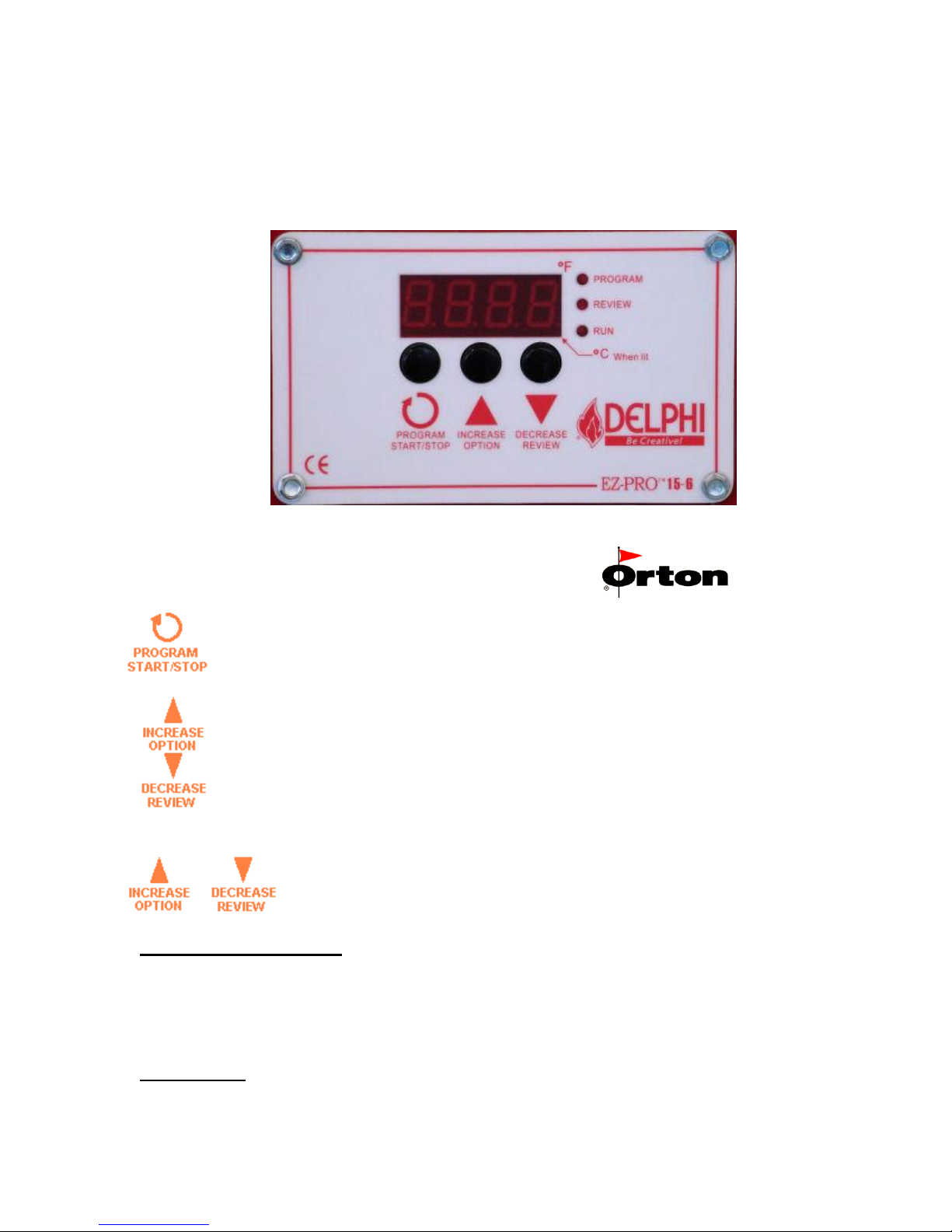
Delphi EZ-Pro Controller
`
This button is for selecting a firing program and advancing through the programming steps. After
programming is complete, use this button to Start and Stop the firing.
This button is used to change the firing program during programming and to change the display values for
specific program settings. During a firing, use this button for special firing options (including Skip Step).
This button is used to change the display values for specific program settings. It is also used to activate the
Program Review feature.
When using the Increase and Decrease buttons to change number settings, the values will
change more rapidly if the button is held in.
Status Indicator Lights
3 lights are located to the right of the display.
Program lit during controller programming
Review lit during Program Review.
Run lit (blinks) during an active firing.
Audible Alarm
The controller is equipped with a small buzzer that will sound during button presses and at the
successful completion of a firing for 30 seconds. The alarm will also sound to notify you of
Page 14

14
diagnostic alarms that may occur during a firing. To silence an active buzzer, Press any
button.
Temperature display preference
All temperature displays on the controller can be viewed as F (Fahrenheit) or C
(Celsius). The temperature display preference is set by positioning a small circuit board
jumper on the back side of the controller that is labeled C/F. The C/F jumper has 2 pin
positions, when installed on the 2 corresponding circuit board pins the controller will
display all temperatures as F(Fahrenheit). When no jumper is installed on the 2 circuit
board pins the controller will display all temperatures as C (Celsius). To determine if
your controller is set for F or C without viewing the jumper position, the small decimal
point light in the bottom right-hand corner of the display panel indicates F or C. If this
decimal point light is lit, the controller is set for C.
The C/F jumper position is shown on the wiring diagram included in this manual (page
29).
Temperature Measurement
The controller monitors and controls temperature from a single Type K thermocouple
sensor. The thermocouple probe extends into the firing chamber to measure the
temperature. Use caution to avoid damage to the system thermocouple. If the probe is
damaged, the controller may not function properly.
Temperature Control
The controller heats the firing chamber by turning relays on and off at the appropriate
rate to maintain the program schedule. It is normal to hear the clicking noises associated
with turning relays on and off throughout the firing.
Firing Program Terminology
As we begin our discussion on programming your kiln, it may be handy to first discuss
basic fusing terminology and fusing techniques.
All modern electronic kiln controllers require three pieces of information for each heating
or cooling step (commonly called a ”segment”) of a firing schedule. These variables are:
Heating or cooling rate (speed, commonly referred to as Ramp Rate)
Heating or cooling temperature (Target, or Set Point Temperature)
Time Spent at a specific heating or cooling temperature (Hold or Soak Time)
The following graphical representation of a “typical” firing schedule may help you
visualize exactly what your kiln does. A complete firing schedule can be multiple heating
and/or cooling steps or segments. However, for many applications a single step is all
that is required. The maximum number of program segments in the EZ-Pro controller is
limited to 8.
Page 15

15
Ramp Rate
Each step of a firing program must have a programmed Rate of temperature increase or
decrease. These rate values are selected as Degrees per Hour. During the
programming the display prompt for Rate settings are rA followed by the step number
like rA1, rA2, rA3, etc… This may be either a positive number (for heating), or a
negative number for cooling. To heat or cool as fast as possible, an alternative setting is
available at the beginning or end of the temperature range. This setting appears as
FULL on the controller display. If zero is set for any rate, this tells the controller that
there are no more steps to your firing schedule, and ends your program. This feature
can also be used to erase an entire firing program by setting the first rA1 value to zero.
The ramp rates built in to the controller were selected to give optimum performance for
most projects. You may need to modify this part of the firing schedule if you have a
special project.
Target or Set Point Temperature
After the ramp rate has been set, the target hold temperature is then selected. Once
again, the built in temperatures are suitable for a typical project, by may need to be
modified for certain special projects.
Hold / Soak Time
Hold or soak times are important parts of the firing cycle. The heat soak, or heat hold,
allows both the kiln and glass to completely stabilize before continuing to the specified
high temperature. The cooling soak or hold (also called the pre-annealing soak),
commonly at about 975oF to 1000oF degrees allows stress built up in the cooling glass to
be released slowly. Without the cooling soak, the glass could retain stress resulting in
breaks.
Page 16

16
Program Modes
The EZ-Pro controller allows the operator to select 1 of 5 program modes for different
glass art or craft applications.
The program mode is prompted on the controller display when the controller is turned
on. The 5 available modes are
-90- For 90 COE glass projects
-96- For 96 COE glass projects
bEAd For bead annealing projects
CLA For Metal Clay projects
USr For custom firings
To change the program mode the controller display should be showing the IdLE
message. (When the kiln is first turned on, the IdLE message should appear after about
5 seconds.) Press and hold the Increase button for about 7 seconds until the display
shows the code CFG. Release the Increase button and press the Program button to
view the CFG code alternating with the current mode setting. Press the Increase or
Decrease buttons to select a new mode setting. When the desired mode appears on the
controller display, press the Program button to return the controller display to the IdLE
message. The new program mode can be confirmed by turning the controller off and
back on to view the new start up message.
Changing Program Modes
All program edits and custom firing schedules are saved in the controller memory. If you
change the Program Mode, the edits you have saved in one Program Mode will not be
reset or erased. All program changes will be available the next time you return to the
same Program Mode.
Selecting the Firing Schedule or Programs
After selecting a Program Mode, to select any of the available programs, first press the
Program button when the display shows IdLE. The last used program will be the first
choice on the controller display. If a different program is desired, press the Increase
button to see another program. Then press the Program button again when the display
shows the program code you want. The available programs will be in the order below:
→ Preset Programs → PrO1 → PrO2→ PrO3→ PrO4→
After selecting a program continue to press the Program button to step through the
program settings (each setting can be changed if desired by pressing the increase or
decrease buttons to edit the values), at the end of the program settings, the display will
show the message Strt. Press the Program button again to start the firing, the controller
display will show the message -On-.
To stop a firing after it has been started. Press the Program button and the controller
display will show StOP. Press the Program button again to return to the IdLE message.
Page 17

17
-90- Program Mode
The 90 COE mode provides 4 preset firing schedules for glass forming and 4 optional
User Programs for creating custom firing schedules. The 4 preset programs are
recommended firing schedules that can also be customized if necessary. These
programs provide the various heating and cooling steps for easy selection.
Full Fuse Displayed as FUSE
This program heats at 300F/hour to 1250F and holds this temperature for 30 minutes.
Then heats at 600F/hour to 1480F and holds this temperature for 10 minutes. Then
cools rapidly to 960F and holds this temperature for 40 minutes. Then cools at
150F/hour to 700F and shuts off.
Tack Fuse Displayed as tAC
This program heats at 300F/hour to 1250F and holds this temperature for 30 minutes.
Then heats at 400F/hour to 1350F and holds this temperature for 10 minutes. Then
cools rapidly to 960F and holds this temperature for 60 minutes. Then cools at
100F/hour to 700F and shuts off.
Slump Displayed as SLP
This program heats at 300F/hour to 1270F and holds this temperature for 15 minutes.
Then cools rapidly to 960F and holds this temperature for 60 minutes. Then cools at
100F/hour to 700F and shuts off.
Fire Polish Displayed as POL
This program heats at 300F/hour to 1180F and holds this temperature for 10 minutes.
Then cools rapidly to 960F and holds this temperature for 60 minutes. Then cools at
100F/hour to 700F and shuts off.
Program Rate Temp Hold
FUSE 300F/hour 1250F 00.30
600F/hour 1480F 00.10
FULL 960F 00.40
150F/hour 700F 00.00
tAC 300F/hour 1250F 00.30
400F/hour 1350F 00.10
FULL 960F 01.00
100F/hour 700F 00.00
SLP 300F/hour 1270F 00.15
FULL 960F 01.00
100F/hour 700F 00.00
POL 300F/hour 1180F 00.10
FULL 960F 01.00
100F/hour 700F 00.00
Page 18

18
The preset 90 COE programs can be edited. Each program segment can be
changed by the operator. To restore the factory values, enter a zero value for the
first rA1 segment of each program and press the Program button.
In addition to the 90 COE preset programs, the -90- mode provides 4 User
defined programs for custom firing schedules. Each user defined program can be
up to 8 steps. The User programs are;
Program Rate Temp Hold
PrO1 Undefined Undefined Undefined
PrO2 Undefined Undefined Undefined
PrO3 Undefined Undefined Undefined
PrO4 Undefined Undefined Undefined
-96- Program Mode
The 96 COE mode provides 4 preset firing schedules for glass forming and 4
optional User Programs for creating custom firing schedules. The 4 preset
programs are recommended firing schedules that can also be customized if
necessary. These programs provide the various heating and cooling steps for
easy selection.
Full Fuse Displayed as FUSE
This program heats at 300F/hour to 1220F and holds this temperature for 30
minutes. Then heats at 600F/hour to 1465F and holds this temperature for 10
minutes. Then cools rapidly to 960F and holds this temperature for 40 minutes.
Then cools at 100F/hour to 800F and shuts off.
Tack Fuse Displayed as tAC
This program heats at 300F/hour to 1250F and holds this temperature for 30
minutes. Then heats at 400F/hour to 1310F and holds this temperature for 10
minutes. Then cools rapidly to 960F and holds this temperature for 60 minutes.
Then cools at 100F/hour to 800F and shuts off.
Slump Displayed as SLP
This program heats at 300F/hour to 1250F and holds this temperature for 15
minutes. Then cools rapidly to 960F and holds this temperature for 60 minutes.
Then cools at 150F/hour to 800F and shuts off.
Fire Polish Displayed as POL
Page 19

19
This program heats at 300F/hour to 1165F and holds this temperature for 10
minutes. Then cools rapidly to 960F and holds this temperature for 60 minutes.
Then cools at 100F/hour to 800F and shuts off.
Program Rate Temp Hold
FUSE 300F/hour 1220F 00.30
600F/hour 1465F 00.10
FULL 960F 00.40
100F/hour 800F 00.00
tAC 300F/hour 1250F 00.30
400F/hour 1310F 00.10
FULL 960F 01.00
100F/hour 800F 00.00
SLP 300F/hour 1250F 00.15
FULL 960F 01.00
150F/hour 800F 00.00
POL 300F/hour 1165F 00.10
FULL 960F 01.00
100F/hour 800F 00.00
The preset 96 COE programs can be edited. Each program segment can be
changed by the operator. To restore the factory values, enter a zero value for the
first rA1 segment of each program and press the Program button.
In addition to the 96 COE preset programs, the -96- mode provides 4 User
defined programs for custom firing schedules. Each user defined program can be
up to 8 steps. The User programs are;
Program Rate Temp Hold
PrO1 Undefined Undefined Undefined
PrO2 Undefined Undefined Undefined
PrO3 Undefined Undefined Undefined
PrO4 Undefined Undefined Undefined
bEAd Program Mode
The bEAd mode provides 3 preset firing schedules for bead annealing and 4 optional
User Programs for creating custom firing schedules. The 3 preset programs are
recommended firing schedules that can also be customized if necessary. These programs
provide the various heating and cooling steps for easy selection.
½” beads batch annealing Displayed as bd 1
This program heats at 500F/hour to 980F and holds this temperature for 5 minutes. Then
cools at 300F/hour to 670F and shuts off.
1” beads batch annealing Displayed as bd 2
Page 20

20
This program heats at 400F/hour to 980F and holds this temperature for 10 minutes. Then
cools at 150F/hour to 670F and shuts off.
2” beads batch annealing Displayed as bd 3
This program heats at 300F/hour to 980F and holds this temperature for 20 minutes. Then
cools at 100F/hour to 670F and shuts off.
Continuous Annealing as you Create Displayed as bd 4**
This program heats rapidly to 960F and holds this temperature for 4 hours. Then rapidly
reheats to 960F to ensure stable annealing temperature and holds for 1 hour. Then cools
at 600F/hour to 400F and shuts off. **This program should only be used in kilns with a properly
installed bead door to „garage‟ hot projects.
Program Rate Temp Hold
Bd 1 500F/hour 980F 00.05
300F/hour 670F 00.00
Bd 2 400F/hour 980F 00.10
150F/hour 670F 00.00
Bd 3 300F/hour 980F 00.20
100F/hour 670F 00.00
Bd 4** FULL 960F 04.00
FULL 960F 01.00
600°/hour 400F 00.00
The preset bead programs can be edited. Each program segment can be changed by the
operator. To restore the factory values, enter a zero value for the first rA1 segment of
each program and press the Program button.
In addition to the bead preset programs, the bEAd mode provides 4 User defined
programs for custom firing schedules. Each user defined program can be up to 8 steps.
The User programs are;
Program Rate Temp Hold___
PrO1 Undefined Undefined Undefined
PrO2 Undefined Undefined Undefined
PrO3 Undefined Undefined Undefined
PrO4 Undefined Undefined Undefined
CLA Program Mode
The CLA mode provides 5 preset firing schedules for metal clay firing and 4
optional User Programs for creating custom firing schedules. The 5 preset
programs are recommended firing schedules that can also be customized if
necessary. These programs provide the various heating steps for easy selection.
PMC+ Fast Displayed as P-FS
Page 21

21
This program heats as fast as possible to 1650°F and holds this temperature for
10 minutes.
PMC+ Slow Displayed as P-SL
This program heats at 1500°F/hour to 1470°F and holds this temperature for 30 minutes.
PMC3 Slow Displayed as P3SL
This program heats at 1500°F/hour to 1110°Fand holds this temperature for 45 minutes.
PMC Standard Displayed as Std
This program heats as fast as possible to 1650°F and holds this temperature for 2 hours.
PMC Gold Displayed as GOLd
This program heats as fast as possible to 1290°F and holds this temperature for 90
minutes.
Program Heating Rate Temp Hold
P-FS Full Power 1650F 00.10
P-SL 1500F/hour 1470F 00.30
P3SL 1500F/hour 1110F 00.45
Std Full Power 1650F 02.00
GOLd Full Power 1290F 01.30
The preset metal clay programs can be edited. Each program segment can be changed
by the operator. To restore the factory values, enter a zero value for the first rA1
segment of each program and press the Program button.
In addition to the metal clay preset programs, the CLA mode provides 4 User defined
programs for custom firing schedules. Each user defined program can be up to 8 steps.
The User programs are:
Program Rate Temp Hold ___
PrO1 Undefined Undefined Undefined
PrO2 Undefined Undefined Undefined
PrO3 Undefined Undefined Undefined
PrO4 Undefined Undefined Undefined
User Program Mode
The USr mode provides 6 User Programs for creating custom firing schedules.
You can store/save up to 6 separate custom firing programs in the controller
memory. Each program can be up to 8 Steps long. During programming the
display prompts for the individual firing schedules are PrO1, PrO2, PrO3, PrO4,
PrO5 and PrO6.
Programming Heating and Cooling Rate
Page 22

22
Each step of a firing program must have a programmed Rate of temperature
increase or decrease. This is the speed of the heat-up or cool-down. These rate
values are selected as Degrees per Hour. „Degrees per hour‟ rate can be
determined by dividing the total amount of temperature change by the number of
hours required to achieve the temperature change. For Example, If you want to
heat the kiln to 900°F from room temperature (72°F) in 2 hours time. The heating
rate would be 414 Degrees/hour. [900-72 = 828, 828/2 = 414]
During programming the display prompts for all Rate settings is
rA followed by the step number like rA 1, rA 2, rA 3, etc…
The values available for setting Rate are 0-1798°F/hour or 0-998°C/hour. If it‟s
desired to heat or cool as fast as possible, an alternative setting is available at
the beginning or end of the temperature range. This setting appears as FULL on
the controller display.
Entering Zero for a heating or cooling rate
The controller determines where your firing program ends by the rA value. If zero
is set for any Rate, this tells the controller that there are no more steps to your
firing schedule. If additional steps had previously been saved in the active
program, all steps after the zero entry will be erased. This feature can also be
used to erase an entire firing program by setting the first rA 1 value to zero.
Programming Heating or Cooling Temperatures
Each step of a firing program must have a programmed heating or cooling
temperature. The controller must have at least one heating step to accept the
firing program as valid (an invalid program results in a bAdP display alarm). A
heating step is simply any step with a temperature setting that is above the
current display temperature.
Cooling steps are automatically determined by the temperature value. If a
heating or cooling temperature value is programmed to a lower setting than the
previous heating or cooling temperature, it will be a cooling step.
During programming the display prompts for all Heating or Cooling Temperature
settings is °F (or °C) followed by the step number like
°F 1, °F 2, °F 3, etc…
The temperature range available for setting heating or cooling temperatures is
32-2400°F or 0-1316°C. If the controller does not allow you to program
temperatures up to 2400°F/1316°C, it has been factory set by the supplier to a
lower safety temperature. This is often necessary to limit the controller to the
maximum operating temperature of the system.
Programming Hold Time
Each step of a firing program can have an optional Hold time. Hold time is the
amount of time you want to stay at the previously determined heating or cooling
temperature. Hold time is also referred to as Soak or Dwell time.
Page 23

23
Hold Time is entered in Hours & Minutes format. The middle decimal point light
on the controller display is used to separate Hours from Minutes. For Example, a
1 hour hold time should be set like [01.00], while a 1 hour and 30 minute hold
time would be [01.30]. If no hold time is desired, the setting should be [00.00]
A special Hold time is available for indefinite Hold periods. If it is desired to hold
the program temperature until someone manual stops the firing or manually
advances the program, a hold time of [99.59] represents indefinite Hold.
The value range available for setting Hold time is 00.00 to 99.58.
During a firing, the hold time begins as soon as the temperature reaches the
heating or cooling temperature. As the hold time progresses, the controller
display will count-down the remaining time until the hold time has expired.
During programming the display prompts for all Hold settings is HLd followed by
the step number like HLd1, HLd2, HLd3, etc…
Other Programming Notes
After a firing program is set in the controller, the values will not change or be lost
when the controller is turned off.
It is not possible to back-up in the programming mode. If a mistake is made while
programming a previous step, you must start over from the IdLE mode to make
corrections.
If no buttons are pressed for 1 full minute during programming, the controller will
automatically exit the program mode and return to the IdLE display. During a
firing, if the options menu is activated for programming, the controller will return
to the active display if no buttons are pressed for 1 full minute.
Delay Start Option
Prior to the active start of any firing, the controller display will show a Start
prompt of Strt. This appears after the firing program selection and programming.
If a delay start time is desired, press the Decrease/Review button to activate a
delay start prompt. The display will show dELA alternating with the adjustable
delay time in Hours & Minutes format. Use the Increase/Decrease buttons to set
the Delay time and then press the Program button to return to the Strt prompt.
When you are ready to begin the delay period, press the Program button again.
Delay time counts-down on the controller display before the actual start of the
firing. When the delay time expires, the actual firing program begins
automatically. The Delay time has a setting range of 00.00 (no delay) to 99.59
(99 hours. 59Minutes)
An active delay time can be canceled by pressing the Program/Start button any
time during the delay count-down to begin the actual firing.
Page 24

24
Thermocouple Offset Option
Thermocouple Offset allows you to correct the temperature display a few
degrees in a positive or negative direction. This can improve the controller
accuracy if the thermocouple probe is aged or if the firing results appear to be
slightly under or over fired. This offset allows you to make minor adjustments to
the firing temperatures without changing the programmed heating or cooling
temperatures.
Prior to the active start of any firing, the controller display will show a Start
prompt of Strt. This appears after the firing program selection and programming.
If a thermocouple offset is desired, press the Increase/Skip button to activate a
thermocouple offset prompt. The display will show tCOS alternating with the
adjustable offset value. Use the Increase/Decrease buttons to set the Offset and
then press the Program button when you are ready to return to the Strt prompt.
Thermocouple offset (tCOS) has a limited offset range of +/-20°F (+/-11°C). A
positive correction will increase the controller display temperature by the amount
selected. This will make the firing temperatures lower. A negative correction will
decrease the controller display temperature by the amount selected, making the
firing temperatures higher.
Program Review
Any time during an active firing, the Program Review feature can be activated to
show you the complete firing schedule on the controller display. Press the
Decrease button to activate the Program Review. Each segment of your firing
schedule will scroll automatically on the display for a few seconds each. To
cancel the Review in process, simply press any button.
Program Review can also be activated when the controller is IdLE or during
program selection. After this type of Program Review, the controller advances
directly to the Strt prompt. The Review can be used to bypass making any
changes to the current firing schedule.
Program Recall
Program Review can be used to quickly select any firing schedule that is already
programmed into the controller memory. To select a saved program, the
controller should first be at the IdLE prompt. Press the Increase button until the
display shows the desired program, then press the Decrease button to
automatically load the program and to review the program settings. At the end of
automatic program review, the controller will go directly to the Strt prompt and
the firing can be started with one more press of the Program button. Only use the
quick program recall to start a new firing if no changes are required for the entire
firing program.
Page 25

25
Options Menu
During an active firing, the Increase button will activate an options menu and
scroll through the available options with each button press. These options allow
you to make adjustments to the firing program without stopping the firing. The
available options follow.
Skip Step
During an active heating, cooling or hold time, it is possible to skip ahead to the
next program step. Press the Increase button to display the Skip Step prompt
SStP. Then Press the Program button to display the current ramp or hold
segment. Press the Program button again to initiate the Skip and the controller
display returns to the normal firing mode. If the Decrease button is pressed, the
Skip function is canceled and the controller display returns to the normal firing
mode.
The Skip function can be used to end a Hold time early or to skip from any
heating/cooling step to the next heating/cooling step. The Skip function does
nothing during the final program step. To end a final program step, simply press
Stop.
Add Hold Time
During an active heating, cooling or hold time, it is possible to add more Hold
time to the current program step. Press the Increase button until the Hold Time
prompt HLdt is displayed. Then Press the Program button to display the current
hold time. Press the Increase button to add 5 minute increments to the original
Hold time. Then Press Program button to return to the normal firing mode. If the
Decrease button is pressed while the HLdt prompt is displayed, the controller
display returns to the normal firing mode.
Change Heating/Cooling Temperature
During an active heating, cooling or hold time, it is possible to change the heating
or cooling temperature of the current program step. Press the Increase button
until the Change Temperature prompt CHGt is displayed. Then Press the
Program button to display the current temperature setting. Adjust the
temperature setting with the Increase or Decrease buttons. Then Press Program
button to return to the normal firing mode. If the Decrease button is pressed while
the CHGt prompt is displayed, the controller display returns to the normal firing
mode.
Threshold Alarm
During the firing, it is possible to set an audible alarm and display alarm for when
the actual temperature reaches a specified value. The buzzer will sound (for 30
seconds) and the display will show the alarm code ALAr.
Page 26

26
To set the alarm, Press Increase button during the active firing until the alarm
prompt ALAr is displayed. Then Press the Program button to display the current
alarm temperature setting. Adjust the temperature setting with the Increase or
Decrease buttons. Then Press Program button to return to the normal firing
mode. If the Decrease button is pressed while the ALAr prompt is displayed, the
controller display returns to the normal firing mode.
The alarm is disabled (turned off) when the alarm value is set to 32°F (0ºC). The
alarm value can be reset or changed many times during a single firing. To silence
an active alarm, simply press any button. The maximum programmable value for
the alarm is 2400ºF (1316ºC). If the controller does not allow you to program
alarm temperatures up to 2400°F/1316°C, it has been factory set by the supplier
to a lower safety temperature. This is often necessary to limit the controller to the
maximum operating temperature of the system.
Flow Diagram for Options Menu
Power Fail Recovery
A firing will resume after a power interruption if certain conditions are met.
1. The controller was not performing a cooling step and the cooling
temperature was not exceeded. If so, the display will show the alarm code
PF 1 and terminate the firing.
2. When power is restored the actual temperature must be above 212ºF
(100ºC). If not, the display will show the alarm code PF 2 and terminate
the firing.
Page 27

27
3. When power is restored, the temperature drop during the power
interruption must be less than 72ºF (40ºC). If not, the display will show the
alarm code PF 3 and terminate the firing.
Status Display Codes
Below is a list of normal display codes which indicate the controller mode of
operation.
IdLE - This is ready mode; No firing in process. This message will alternate with
the temperature display and/or any alarm messages that may occur.
dELA - This is the delay start mode. This message will alternate with the delay
time count-down if programmed.
Strt - This is a final prompt before starting a new firing. The Delay start and
thermocouple offset features are accessed from this prompt.
-On- - This is a short (5 second) display that indicates a new firing has been
started.
StOP - This is an Abort message; the firing was stopped early. This message
will alternate with the temperature display and/or any alarm messages that may
occur.
CPLt - This is a firing complete message; the firing ended successfully. This
message will alternate with the temperature display and the total firing time from
start to finish.
-90-, -96-, bEAd, CLA, USr - This is a short (5 second) display of the Program
Mode which appears every time the controller is turned on.
Alarm Display Codes
In addition to Power failure alarms, these messages may be displayed if the
controller detects a problem during the firing.
tC - This alarm will appear when the kiln is idle and indicates that the
thermocouple sensor is no longer detected. The controller can not operate
without a thermocouple signal. In most cases, the thermocouple has failed and
will need replacement, or the electrical connections for the thermocouple may be
loose or damaged. Check the wiring for the thermocouple and the physical
condition of the probe inside the firing chamber.
tCr - This alarm indicates that the thermocouple sensor is detected but the
signal is reversed. The firing was terminated. The thermocouple signal is a low
voltage direct current with +/- polarity. The controller will sense that the
temperature is traveling backwards from what is expected. In most cases, this
indicates that the thermocouple needs to be reconnected properly. Check the
wiring for the thermocouple.
Page 28

28
FAIL - This alarm will appear during an active firing and indicates that the
thermocouple sensor is no longer detected. The signal was lost during and the
firing was terminated. The controller can not operate without a thermocouple
signal. In most cases, the thermocouple has failed and will need replacement, or the
electrical connections for the thermocouple may be loose or damaged. Check the wiring
for the thermocouple and the physical condition of the probe inside the firing chamber.
FtL - This alarm indicates that the firing was taking too long to complete and the firing
was terminated. The controller monitors the deviation from the desired firing schedule as
compared with the actual firing results. There are 2 conditions for the FtL alarm.
1. The heating or cooling rate is slower than 27°F (15°C) per Hour
2. The current program step has lasted 2 hours longer than anticipated.
In most cases, the FtL alarm occurs during heating if the heating rate is set to a fast
speed that cannot be maintained by the kiln. If the heating rate is within the systems
capability, a component failure has probably occurred with the heating elements or the
heater relays.
During cool-down, a well insulated system will have cooling limitation and rapid cooling
rates may set off this alarm if the cooling speed cannot be maintained. Increasing the
final cool-down temperature or slowing the programmed cooling rate can avoid this
alarm.
tCL - This alarm indicates that the thermocouple signal is not responding to the
demand for more system power during heat-up. There are 3 conditions for the tCL
alarm.
1. The heating rate is slower than 9°F (5°C) per Hour
2. The actual kiln temperature is lagging behind the desired setpoint temperature by
more than 100ºF (56ºC).
3. The actual temperature is less than 500ºF (260ºC)
In all cases, the tCL alarm occurs during heating when little temperature rise is detected.
This can be the result of a component failure; most likely a failed heating elements or a
heater relay. Another possible problem is with the thermocouple sensor signal; if the
thermocouple probe is not properly positioned in the firing chamber or if the wiring from
the thermocouple has short-circuited the controller will not detect actual temperature
changes in the firing chamber.
EtH - This alarm indicates that the Electronics temperature is too hot for controller
operation. The controller temperature must be below 176ºF (80ºC) to prevent damage to
the electronic components. The EtH alarm cannot be cleared unless the board
temperature has cooled. If the EtH occurs frequently, check the kiln for heat loss near
the controller. Proper venting and heat-shielding should be inspected.
HtdE -The High Temperature deviation alarm sounds an audible alarm and terminates
the firing if the actual kiln temperature is above the controller set-point by 56ºC (100ºF).
This alarm is active only when the actual kiln temperature is above 500ºF (260ºC)
Page 29

29
FE # - Fatal software Errors, FE Alarms indicate a hardware failure or software
problem with the controller. These alarms will disable the normal controller
operation and require corrective action. If a Fatal Error occurs during an active
firing, the firing is terminated. These alarms include;
FE 1 – Failed to read or write to memory device
FE 2 – Failed memory test during power on
FE 3 – Corrupt data found in memory
FE 4 – Errors detecting thermocouple input signal
FE 5 – Software Execution failed
Turn the controller off and back on, then press any button to try and clear the
alarm. If the alarm reoccurs immediately or frequently, the controller may require
service or replacement.
FE 4 alarms can often be solved by correcting problems with the system thermocouple.
Loose connections or faulty thermocouple wiring or a faulty thermocouple can result in
this alarm.
Wiring Diagram
If your kiln is set up in an unheated area, and is left idling overnight, and the
room temperature has dropped to, say, 20 degrees, you may see an alarm code
TcR (thermocouple reversed) when you attempt to run a new firing in the
morning. Merely shut off the kiln and re-start. Things should then function
Special Note
normally.
Page 30

30
FUSED GLASS PROJECTS
Working with Tested Compatible Glasses
To ensure success when fusing glass, use glass that has been pre-tested by the
manufacturer
How to prepare your glass project
Select glass that is “tested compatible” and has the same COE (Coefficient of
Expansion) for the entire project.
Glass projects should be comprised of two or more layers of glass from edge to
edge because at a full fuse, glass likes to be approximately ¼” (6mm) thick. The
best designs are constructed using a single piece of glass for the base piece,
with a cut design as the second layer. If you‟d like you can add more detail to
your design with frit, stringers, and confetti. During assembly, take the time to
make sure your glass pieces fit well together. If necessary, use a glass grinder
to aid with the fit. A helpful tip to reducing and eliminating grinder marks from
showing up in your fused pieces is to use an extra fine grit grinder bit.
Oil from your glass cutter, as well as oil from your fingers while handling the
pieces, is left on the surface of the glass. Thoroughly clean your glass pieces
with either a light detergent, like Dawn dishwashing detergent, and water or with
denatured alcohol. If you did any heavy grinding, also use a soft bristled brush,
like an old toothbrush, to scrub the edges and remove any residual ground glass
debris. After the glass had been cleaned and dried well, only handle it by the
edges when assembling your project.
To make transporting your project between your workspace and the kiln easier,
you can use water soluble glue. Use glue very sparingly on the backside of the
glass. Allow the glue to completely dry before you try to move your piece.
Before setting up your glass projects on the kiln shelf, first place the kiln shelf in
the kiln. If you are planning to fire more than one piece at a time, make sure to
position your glass projects no closer than ¾” to 1” to each other and also no
closer to the edge than ¾”.
Firing your Glass Project
When you first start fusing, the entire process
may seem to be complicated, but it‟s really
simpler than it may have originally sounded.
Fusing is all about controlled heating and
cooling of glasses in a kiln. As glass is being
fired in a kiln it goes through many physical
changes based on the temperature zone that
it‟s in.
Below 1000°F (538°C), glass is very rigid and is very susceptible to thermal
shock, or breaking, if heated or cooled too quickly. Visually, the glass appears to
be very rigid and it will look the same as if it were room temperature. Resist the
temptation to open the kiln and peek inside, because glass is very fragile at this
point and large temperature swings in the kiln will cause the glass to break.
Page 31

31
Between 1000°F and 1250°F (538°C – 677°C), the glass is softening, becoming
more pliable, and starting to act more like a liquid and less like a solid. At the top
end of this temperature range, glass will slump if held for a period of time.
Visually the top layer of the glass will begin to soften and round over on the
edges and the sides will start to become wet and glossy looking, or fire polished.
At this point, the layers of glass haven‟t begun to stick together yet.
Between 1250°F and 1350°F (577°C - 732°C), the glass is becoming even softer,
and at the top end of this range will be fully slumped. It‟s not recommended to
exceed 1350 F if you are slumping because at higher temperatures, there is a
loss of control of the glass and it may slide down too far or unevenly into the
mold. Visually the edges have softened and rounded even more and the surface
is very glossy. If your project is held for an extended period of time in this
temperature zone, it will be more prone to devitrify. Devitrification is the
compositional change of the glass from an amorphous material to a more
crystalline structure. As the molecules crystallize, devitrification appears to cloud
the surface of the glass.
Between 1350°F and 1400°F (732°C – 760°C), the glass will have very round
edges on the surface and will stick together and become fully tack fused.
Between 1400°F and 1500°F (760°C – 816°C) the glass becomes more fluid and
fully melts together at the higher end of this temperature range, which is a full
fuse.
Firing Process
In fusing, the fired appearance of the glass is referred to as the firing process for the
purpose of a selecting a firing schedule.
Full Fuse: The glass has been completely melted together into
one solid piece of glass that is smooth on the
surface and all of the edges are well rounded.
Tack Fuse: Glass has a textural feel on the surface. All the
edges of the surface pieces are well rounded and
fully attached to the base glass.
Slumping: The glass has been placed onto a mold and bent to
shape and conform to the mold.
Fire polish: All surfaces of the glass have been fired to a glossy
finish, yet the outside edges of the piece are crisp,
clean, and somewhat square.
Page 32

32
Firing stages
Initial Heating from Room Temperature (room temperature to 1200°F range):
During the initial heating, the glass is very brittle and susceptible to breaking (thermal
shock) if it‟s heated up too quickly. During this stage, it‟s best to take a conservative
approach and slowly heat up the glass. At the end of this range, it‟s a good idea to add
a heat soaking period to allow the project to equalize to the same temperature
throughout. Never peek in the kiln during this stage, or you risk thermal shock breakage.
Process Heating (1200°F to 1500°F range): The glass becomes softer and more fluid.
During the process heating stage, the glass can be fired more quickly to the target
temperature and soaked only long enough to achieve the desired look. It‟s important not
to hold the project at these temperatures for a long period of time, or you run the risk of
devitrification (a visible clouding of the glass surface due to crystallization).
Fast Cooling (1500°F to 1100°F range): After the finished look has been achieved,
it‟s important to cool the inside of the kiln and the glass as quickly as possible to stop the
firing action so that it “freezes”. During the fast cooling stage, the surface of the glass is
cooler and it has contracted more than the heated center which remains expanded, thus
introducing stress into the glass piece.
Annealing (1100°F to 700°F range): At the beginning of the annealing stage, it‟s
necessary to heat soak the glass for an extended period of time to allow the glass to
equalize in temperature throughout and release the stress that‟s in the glass. This
makes the glass more stable. Then the glass is slowly cooled through the annealing
temperature range to better ensure the glass piece is free of internal stresses and is
physically stronger. NEVER OPEN THE KILN DURING THIS STAGE!
Cooling to Room Temperature (700°F to room temperature range): After the glass
temperature has cooled below the annealing temperature zone, the kiln can be turned
off to allow it to cool at it‟s own pace to around 150°F – 200°F. Again, to avoid thermal
shock, do not open the kiln until it has cooled down to at least 200°F. Even at this
temperature, the glass is very hot, so do not attempt to pick it up in your bare hands.
Simply open up the lid of your kiln and allow the glass and the kiln shelf to cool down to
room temperature.
Factors to consider before selecting a firing schedule
First envision what you want your finished piece to look like and ask yourself the
following questions:
What is the size (diameter) of the piece? How many layers thick will it be?
What is the desired finished look?
Will it be a full fuse, a more textural tack fuse, a combination of both?
Will it be slumped or draped to become a more 3 dimensional and possibly
functional piece?
Will it be embellished with any surface decorations like enamels or metallic
paints?
Page 33

33
The size of your project is defined by both the diameter of the piece as well as the
number of layers of glass. Glass as a material is a very poor heat conductor. The larger
or thicker your project is, the more slowly it needs be fired so that the glass has more
time to heat or cool evenly all of the way through.
Imagine that you are going to bake a cake. You have set your oven on preheat to heat it
up quickly, put the cake into the oven to bake, and forgot to change the dial setting to
bake. When the timer goes off, you look in the oven and discover that the cake is
overcooked and possibly burned on the edges, yet the center is still sunken and
uncooked.
It‟s just the same for glass. If you heat the glass too quickly, the edges may be fused to
the desired finish you like, but the center hasn‟t finished fusing. One solution would be
to soak the piece at the process temperature for a longer period of time, but you are also
taking the risk that devitrification (visible clouding due to crystallization) on the surface or
that the edges will over fire and have an unusual appearance.
Another possible scenario is that the edges of the glass have melted more quickly,
trapping a large amount of air in the center of the piece which expands into large
bubbles within the glass, thus distorting the design.
Both scenarios could have been avoided simply by slowing down the firing program.
Think about your finished piece again. You are creating a 10” bowl that will have a full
fused appearance with some added textural design elements that will be added using
liquid stringer. The finished appearance will also have Hanovia gold added as accents
and be slumped into a 10” bowl mold.
Seldom can a fused piece be finished in one firing. It‟s usually necessary to fire your
piece multiple times in order to achieve the finished look that you have envisioned. With
this in mind, make a list of the steps that you will need to do to create this piece, then
organize them in order by process temperature from the hottest to the coolest.
Process Process Temperature Program
Full Fuse ~ 1470°F FUSE
Liquid Stringer ~ 1350°F tAC
Slumping ~ 1250-1275°F SLP
Hanovia Gold ~ 1180-1200°F POL
By order of process, the full fuse is the hottest process and will be the first firing,
followed by 3 different firings to create your original glass art piece.
Page 34

34
FIRING YOUR 90 COE GLASS PROJECT
Please note: All of the pre-programmed firing schedules are based on the slowest
firing schedule for large projects. These programs can be used for all of your glass
fusing regardless of project size.
Begin in the IDLE mode
To begin programming the kiln, it must be in the IdLE mode. This can be determined by
viewing the LED display. The display will alternately display both the current
temperature and the IdLE message. When the kiln controller is first turned on, it will
display the current firing configuration that it is in.
Press (Program) button to return to the IdLE mode.
Select the firing configuration
To determine the current firing configuration:
Press (Increase) button and hold until the LED display shows CFG
Press (Program) button to display the current firing configuration.
To select the correct firing configuration,
Press (Increase) button to scroll to the correct configuration,
-90- 90 COE glass
Press (Program) button to select this configuration.
Once completed the LED display will return to the IdLE mode.
Select the firing program
To select correct firing program:
Press (Program) button to display the current firing program
Press (Increase) button to scroll to the correct program for your project
FUSE Full Fuse
tAC Tack Fuse
SLP Slumping
POL Fire Polishing
Page 35

35
Press (Decrease) button to engage the correct firing program and the LED light beside
“Review” will light up. Additionally, the firing program will begin to display on the LED
display beginning with rA 1. Once the review has been completed, the display will show
Strt.
Press (Program) button and the display will show –On- and begin firing. Note: If you
accidentally selected the wrong program or would like to stop the program, press
(Program) button again and the display will show Stop.
Once the kiln has completed firing, the display will show CPLt and this message will
alternate with the temperature display and the total firing time from start to finish. DO
NOT open the kiln until it has completely cooled and the temperature shows room
temperature.
Page 36

36
FIRING YOUR 96 COE GLASS PROJECT
Please note: All of the pre-programmed firing schedules are based on the slowest
firing schedule for large projects. These programs can be used for all of your glass
fusing needs regardless of project size.
Begin in the IDLE mode
To begin programming the kiln, it must be in the IdLE mode. This can be determined by
viewing the LED display. The display will alternately display both the current
temperature and the IdLE message. When the kiln controller is first turned on, it will
display the current firing configuration that it is in.
Press (Program) button to return to the IdLE mode.
Select the firing configuration
To determine the current firing configuration:
Press (Increase) button and hold until the LED display shows CFG
Press (Program) button to display the current firing configuration.
To select the correct firing configuration,
Press (Increase) button to scroll to the correct configuration,
-96- 96 COE glass
Press (Program) button to select this configuration.
Once completed the LED display will return to the IdLE mode.
Select the firing program
To select correct firing program:
Press (Program) button to display the current firing program
Press (Increase) button to scroll to the correct program for your project
FUSE Full Fuse
tAC Tack Fuse
SLP Slumping
POL Fire Polishing
Page 37

37
Press (Decrease) button to select the firing program and once selected the LED light
beside “Review” will light up. Additionally, the firing program selected will begin to
display on the LED display beginning with rA 1. Once the review has been completed,
the display will show Strt.
Press (Program) button and the display will show –On- and begin firing. Note: If you
accidentally selected the wrong program or would like to stop the program, press
(Program) button again and the display will show Stop.
Once the kiln has completed firing, the display will show CPLt and this message will
alternate with the temperature display and the total firing time from start to finish. DO
NOT open the kiln until it has completely cooled and the temperature shows room
temperature.
Page 38

38
ANNEALING GLASS BEADS
About these annealing programs
Programs 1-3 in this grouping will batch anneal glass beads
made of Bullseye, System96, and Moretti (Effetre) glasses.
Program 4 is set for continuous annealing while you create.
Safety First:
Never try to put a bead already on the mandrel directly into a preheated or actively firing
kiln unless the kiln has a properly installed bead door. You run the risk of electrocution.
To anneal beads in a kiln without a bead door refer to batch annealing below.
What is Batch Annealing?
Batch annealing is simply taking already cooled, room temperature beads, heating them
to annealing temperature and cooling them through a proper annealing cycle. The beads
may either still on the mandrel or previously removed from the mandrel, and should be
placed on the kiln shelf so that none of the beads are touching one another.
FIRING THE KILN
Begin in the IDLE mode
To begin programming the kiln, it must be in the IdLE mode. This can be determined by
viewing the LED display. The display will alternately display both the current
temperature and the IdLE message. When the kiln controller is first turned on, it will
display the current firing configuration that it is in.
Press (Program) button to return to the IdLE mode.
Select the firing configuration
To determine the current firing configuration:
Press (Increase) button and hold until the LED display shows CFG
Press (Program) button to display the current firing configuration.
To select the correct firing configuration,
Press (Increase) button to scroll to the correct configuration,
bEAd Glass beads
Press (Program) button to select this configuration.
Page 39

39
Once completed the LED display will return to the IdLE mode.
Select the firing program
To select the correct firing program:
Press (Program) button to display the current firing program
Press (Increase) button to scroll to the correct program for your project
bd1 Batch annealing beads up to ½” in diameter
bd2 Batch annealing beads up to 1” in diameter
bd3 Batch annealing beads up to 2” in diameter
bd4** For Continuous annealing of all beads.
Press (Decrease) button to select the firing program and once selected the LED light
beside “Review” will light up. Additionally, the firing program selected will begin to
display on the LED display beginning with rA 1. Once the review has been completed,
the display will show Strt.
Press (Program) button and the display will show –On- and begin firing. Note: If you
accidentally selected the wrong program or would like to stop the program, press
(Program) button again and the display will show Stop.
Once the kiln has completed firing, the display will show CPLt and this message will
alternate with the temperature display and the total firing time from start to finish. DO
NOT open the kiln until it has completely cooled and the temperature shows room
temperature.
**This program should only be used in kilns with a properly installed bead door to „garage‟ hot projects.
Page 40

40
FIRING METAL CLAY
Drying Time
Allow your pieces to be completely dried before firing them in the kiln to ensure that they
don‟t warp.
Loading the kiln
If you fire both glass and metal clay in your kiln, it is
recommended that you invest in a second shelf so that you
can fire only glass on the glass kiln shelf, and only metal
clay silver on the other kiln shelf. After firing your PMC
piece, some of the metal particulates impregnate the kiln
shelf and leave stains on the shelf‟s surface. If you fire
glass on the very same shelf, there is a chance that glass
and metal may have a reaction that will result in silver
stains left permanently on the glass.
Pieces that have a flat side can be placed directly onto the
kiln shelf. They can be positioned closely together, but
they shouldn‟t touch.
Pieces that are rounded, hollow or very delicate in composition will need support while
firing so they don‟t collapse. Pour alumina hydrate or vermiculite into an unglazed
ceramic bisque bowl and carefully place the metal clay pieces onto the alumina
hydrate/vermiculite. Again, they can be positioned closely together, but they shouldn‟t
touch.
FIRING THE KILN
Begin in the IDLE mode
To begin programming the kiln, it must be in the IdLE mode. This can be determined by
viewing the LED display. The display will alternately display both the current
temperature and the IdLE message. When the kiln controller is first turned on, it will
display the current firing configuration that it is in.
Press (Program) button to return to the IdLE mode.
Select the firing configuration
To determine the current firing configuration
Press (Increase) button and hold until the LED display shows CFG
Press (Program) button to display the current firing configuration.
Page 41

41
To select the correct firing configuration:
Press (Increase) button to scroll to the correct configuration,
CLA Metal Clay
Press (Program) button to select this configuration.
Once completed the LED display will return to the IdLE mode.
Select firing program
To select the correct firing program,
Press (Program) button to display the current firing program
Press (Increase) button to scroll to the correct program for your project
P-FS Fast Fire PMC+
P-SL Slow Fire PMC+
P3SL Slow Fire PMC3
Std Firing PMC Standard
GOLd Firing PMC Gold
Press (Decrease) button to select the firing program and once selected the LED light
beside “Review” will light up. Additionally, the firing program selected will begin to
display on the LED display beginning with rA 1. Once the review has been completed,
the display will show Strt.
Press (Program) button and the display will show –On- and begin firing. Note: If you
accidentally selected the wrong program or would like to stop the program, press
(Program) button again and the display will show Stop.
Once the kiln has completed firing, the display will show CPLt and this message will
alternate with the temperature display and the total firing time from start to finish. DO
NOT open the kiln until it has completely cooled and the temperature shows room
temperature.
Page 42

42
INTERMEDIATE MODE:
Keeping a log
There is no “one program fits all” firing schedule for kilns. Even supposedly identical
kilns behave slightly differently. Plugging the same kiln into different outlets in your
house may also alter the firing schedule you need. Additionally, different size projects or
different colors of glass will react differently, necessitating changes to your firing
schedules. It is therefore very important for you to keep detailed firing logs whenever you
do a new project or change any parameter in an existing project.
As you gain experience using your kiln, you may find that you need to use the “add hold
time” or the “skip step” sequences (see page 25) to get exactly the results you want. If
this is consistently the case for your particular project, you may want to generate a user
program, written to your desired specifications or modify one of the pre-programmed
firing schedules.
Changing Pre-Programmed Firing Programs
It‟s a fairly simple process to modify any of the pre-programmed firing schedules to suit
your specific needs. If you are relatively new to fusing, or to the use of computer
controls, however, we suggest that you read through the manual and copy one of the
programs in the manual, modifying it as you desire. Once you‟ve test fired the program a
few times, you can either leave it as a user program, or use the new program as a
reference to go back and modify the preset program.
In all instances, keep a log of your firings, especially when you make changes, so you‟ll
be able to track and or troubleshoot when you have unexpected results.
Pages 16 through 23 outline the procedure for programming, or modifying the programs
in the kiln.
Page 43

43
PROFESSIONAL MODE:
Configuration
Pre-
Programmed
Custom
Programs
-90-
4
4
-96-
4
4
bEAd
4
4
CLA
5
4
Usr
0
6
PROGRAMMING CUSTOM FIRING PROGRAMS
You can enter up to 22 custom firing programs in the controller for all of your firing
needs. Each program can contain up to 8 steps (segments).
Special note: All changes made to both the pre-programmed and customer programs
will be permanently be stored in the memory until you change them!
During the programming, the display prompts for the individual firing programs are Pr
followed by the program number like Pr01, Pr02, Pr03, etc.
To select any of the available programs it is first necessary to be in the IdLE mode.
1. Press (Program) button and the last used program will be the first to come up.
2. Press (Increase) button to select the program you would like to enter or change.
3. Press (Program) button again when the display shows the firing program you
want.
4. Press (Program) button to begin programming your firing schedule. The display
will first prompt rA 1 for the rate of the first segment in your program.
5. Press (Increase) or (Decrease) button to change the firing rate. If you‟d like the
rate to be as fast as possible, press the (Decrease) button until the display
changes to 0, then press the (Decrease) button one more time and display will
change to FULL.
6. Press (Program) button to proceed to the set point temperature. The display will
prompt °F 1.
7. Press (Increase) or (Decrease) button to change the set point temperature.
8. Press (Program) button to proceed to the hold time. The display will prompt
HLd1.
9. Press (Increase) or (Decrease) button to change the hold time. Hold time is
entered in Hours and Minutes. For example, a 1 hour hold time should be
entered as 01.00, and a 30 minute hold will read 00.30.
10. To add additional segments, repeat steps 4-9.
Page 44

44
11. If you are programming over an existing program that has more segments than
the current program you are entering, at the beginning of the next segment,
Press (Decrease) button to change the rate to 0
12. Press (Program) button to program the change, and the display will prompt Strt.
13. Press (Program) button to start the kiln.
14. Press (Program) button and the display will show –On- and begin firing. Note: If
you accidentally selected the wrong program or would like to stop the program,
press (Program) button again and the display will show Stop.
Once the kiln has completed firing, the display will show CPLt and this message will
alternate with the temperature display and the total firing time from start to finish. DO
NOT open the kiln until it has completely cooled and the temperature shows room
temperature.
Page 45

45
90 COE Pre-Programmed Firing Programs
FUSE Segment Rate, °/Hr Set Point Temp Hold/Soak Time
Full Fuse 1 300° F 1250° F 30 min
2 600° F 1480° F 10 min
3 Full 960° F 40 min
4 150° F 700° F --
TAC Segment Rate, °/Hr Set Point Temp Hold/Soak Time
Tack Fuse 1 300° F 1250° F 30 min
2 400° F 1350° F 10 min
3 Full 960° F 1 hr 00 min
4 100° F 700° F --
SLP Segment Rate, °/Hr Set Point Temp Hold/Soak Time
Slumping 1 300° F 1270° F 15 minutes
2 Full 960° F 1 hour
3 100° F 700° F --
POL Segment Rate, °/Hr Set Point Temp Hold/Soak Time
Firepolish 1 300° F 1180° F 10 minutes
2 Full 960° F 1 hour
3 100° F 700° F --
Page 46

46
90 COE Custom Firing Programs
USr1
Segment
Rate,
°/Hr
Set Point
Temp
Hold/Soak
Time
1 2
3
4
5
6
7
8
USr2
Segment
Rate,
°/Hr
Set Point
Temp
Hold/Soak
Time
1
2 3
4
5
6
7
8
USr3
Segment
Rate,
°/Hr
Set Point
Temp
Hold/Soak
Time
1
2 3
4
5
6
7
8
USr4
Segment
Rate,
°/Hr
Set Point
Temp
Hold/Soak
Time
1
2
3
4 5
6
7
8
Page 47

47
96 COE Pre-Programmed Firing Programs
FUSE
Segment
Rate,
°/Hr
Set Point
Temp
Hold/Soak
Time
Full Fuse
1
300° F
1220° F
30 min
2 600° F
1465° F
10 min
3 Full
960° F
40 min
4 100° F
800° F
--
TAC
Segment
Rate,
°/Hr
Set Point
Temp
Hold/Soak
Time
Tack Fuse
1
300° F
1250° F
30 min
2 400° F
1310° F
10 min
3 Full
960° F
1 hr 0 min
4 100° F
800° F
--
SLP
Segment
Rate,
°/Hr
Set Point
Temp
Hold/Soak
Time
Slump
1
300° F
1250° F
15 min
2 Full
960° F
1 hr 0 min
3 150° F
800° F
--
POL
Segment
Rate,
°/Hr
Set Point
Temp
Hold/Soak
Time
Firepolish
1
300° F
1165° F
10 min
2 Full
960° F
1 hr 0 min
3 100° F
800° F
--
Page 48

48
96 COE Pre-Programmed Firing Programs
USr1
Segment
Rate,
°/Hr
Set Point
Temp
Hold/Soak
Time
1 2
3
4
5 6
7
8
USr2
Segment
Rate,
°/Hr
Set Point
Temp
Hold/Soak
Time
1 2
3
4
5
6 7
8
USr3
Segment
Rate,
°/Hr
Set Point
Temp
Hold/Soak
Time
1 2
3
4
5
6 7
8
USr4
Segment
Rate,
°/Hr
Set Point
Temp
Hold/Soak
Time
1 2
3
4
5
6
7 8
Page 49

49
bd1 Segment Rate, °/Hr Set Point Temp Hold/Soak Time
Small Beads (1/2") 1 500° F 980° F 5 min
2 300° F 670° F --
bd2 Segment Rate, °/Hr Set Point Temp Hold/Soak Time
Medium Beads (1") 1 400° F 980° F 10 min
2 150° F 670° F --
bd3 Segment Rate, °/Hr Set Point Temp Hold/Soak Time
Large Beads (2") 1 300° F 980° F 20 min
2 100° F 670° F --
bd4 Segment Rate, °/Hr Set Point Temp Hold/Soak Time
Continuous Annealing 1 FULL 960° F 4 hours
as you Create 2 FULL 960° F 1 hour
3 600° F 400° F --
Bead Annealing Pre-Programmed Firing Programs
Page 50

50
USr1
Segment
Rate,
°/Hr
Set Point
Temp
Hold/Soak
Time
1 2
3
4
5 6
7
8
USr2
Segment
Rate,
°/Hr
Set Point
Temp
Hold/Soak
Time
1 2
3
4
5
6 7
8
USr3
Segment
Rate,
°/Hr
Set Point
Temp
Hold/Soak
Time
1 2
3
4 5
6
7
8
USr4
Segment
Rate,
°/Hr
Set Point
Temp
Hold/Soak
Time
1 2
3
Bead Annealing Custom Firing Programs
Page 51

51
4 5
6
7
8
P-FS
Segment
Rate,
°/Hr
Set Point
Temp
Hold/Soak Time
PMC + Fast
1
Full
1650° F
10 min
P-SL
Segment
Rate,
°/Hr
Set Point
Temp
Hold/Soak Time
PMC + Slow
1
1500° F
1470° F
30 min
P3SL
Segment
Rate,
°/Hr
Set Point
Temp
Hold/Soak Time
PMC3 Slow
1
1500° F
1110° F
45 min
STD
Segment
Rate,
°/Hr
Set Point
Temp
Hold/Soak Time
PMC 1 Full
1650° F
2 hr 0 min
GOLd
Segment
Rate,
°/Hr
Set Point
Temp
Hold/Soak Time
PMC Gold
1
Full
1290° F
1 hr 30 min
PMC Pre-Programmed Firing Programs
Page 52

52
USr1
Segment
Rate,
°/Hr
Set Point
Temp
Hold/Soak
Time
1 2
3
4
5
6 7
8
USr2
Segment
Rate,
°/Hr
Set Point
Temp
Hold/Soak
Time
1
2 3
4
5
6
7 8
USr3
Segment
Rate,
°/Hr
Set Point
Temp
Hold/Soak
Time
1
2 3
4
5
6
7 8
USr4
Segment
Rate,
°/Hr
Set Point
Temp
Hold/Soak
Time
1 2
3
4
Metal Clay Custom Firing Programs
Page 53

53
5 6
7
8
USr1
Segment
Rate,
°/Hr
Set Point Temp
Hold/Soak Time
1 2
3
4
5
6
7 8
USr2
Segment
Rate,
°/Hr
Set Point Temp
Hold/Soak Time
1 2
3
4
5
6
7
8
USr3
Segment
Rate,
°/Hr
Set Point Temp
Hold/Soak Time
1 2
3
4
5 6
7 8
USr4
Segment
Rate,
°/Hr
Set Point Temp
Hold/Soak Time
1 2
3
4
5
6
7
8
User Custom Firing Programs (USr)
Page 54

54
USr5
Segment
Rate,
°/Hr
Set Point Temp
Hold/Soak Time
1 2
3
4
5
6
7
8
USr6
Segment
Rate,
°/Hr
Set Point Temp
Hold/Soak Time
1 2
3
4 5
6 7
8
Page 55

55
Orton Controller Limited Warranty
This limited warranty is given only to the immediate purchaser (“Buyer”) of the Autofire®Express kiln controller. This limited
warranty is not transferable. The Edward Orton Jr. Ceramic Foundation (“Orton”) warrants the controller motherboard installed on the
Autofire®Express (“Warranted Components”) to be in good working order under normal operating conditions for a period of one (1)
year from the date of purchase. Should the Warranted Components fail to be in good working order at any time during the stated one
(1) year period, Orton will, at its option, repair or replace the Warranted Components as set forth below. The liability of Orton is
limited to replacement and/or repair at its factory of the Warranted Components that does not remain in good working order. Repair
parts or replacement products will be furnished on an exchange basis and will be either reconditioned or new. All replaced parts or
products become the property of Orton. Following receipt of notice from Buyer of a valid warranty claim and the Autofire®Express
containing the Warranted Components, Orton will perform its obligations under this limited warranty within 10 business days.
Limited warranty service may be obtained by delivering the Autofire®Express during the warranty period to your Orton Supplier or to
The Edward Orton Jr. Ceramic Foundation, 6991 Old 3C Highway, Westerville, Ohio 43082 and providing written proof of purchase
and a description of the defect or problem. Buyer must insure the shipment or assume the risk of loss or damage in transit, prepay
shipping charges to the service location, and use the original shipping container or equivalent. Buyer will be responsible for shipping
and handling charges in excess of US $50.00 incurred by Orton in returning the Autofire®Express to the Buyer after completion of
limited warranty service.
This warranty does not apply to any damage to the Autofire®Express resulting from:
Operation beyond electrical rating.
External sources including, but not limited to, chemicals, heat abuse and improper care.
Improper or inadequate maintenance by Buyer.
Parts or equipment not supplied by Orton.
Unauthorized modification or misuse.
Operation outside environmental specifications.
Improper installation.
Over firing (melting of materials being fired) regardless of the cause of the over firing.
Warranted Components returned for service where no warranted defect is found will be subject to service, and shipping and handling
fees.
If the Warranted Components are not in good working order as warranted above, Buyer‟s sole remedy shall be repair or replacement
of the Warranted Components as provided above.
TO THE EXTENT PERMITTED BY LAW, ALL EXPRESS AND IMPLIED WARANTIES FOR THE WARRANTED
COMPONENTS INCLUDING THE WARRANTIES OF MERCHANTABILITY AND FITNESS FOR A PARTICULAR PURPOSE
ARE LIMITED TO THE ONE YEAR WARRANTY PERIOD COMMENCING ON THE DATE OF PURCHASE, AND NO
OTHER WARRANTY WHETHER EXPRESS OR IMPLIED WILL APPLY TO THIS PERIOD. TO THE EXTENT PERMITTED
BY LAW, ORTON‟S REMEDY AND BUYER‟S SOLE REMEDY IS LIMITED SOLELY AND EXCLUSIVELY TO REPAIR OR
REPLACEMENT AS SET FORTH HEREIN. ORTON SHALL NOT BE LIABLE FOR, AND BUYER‟S REMEDY SHALL NOT
INCLUDE ANY INCIDENTAL, CONSEQUENTIAL OR OTHER DAMAGES OF ANY KIND WHATSOEVER, WHETHER A
CLAIM IS BASED UPON THEORY OF CONTRACT, NEGLIENCE OR TORT.
Buyer shall determine suitability of the Autofire®Express for the intended use and assume all risk and liability therewith. Some states
do not allow this exclusion or limitation of incidental or consequential damages, so the above limitation or exclusion may not apply to
you. This warranty gives you specific legal rights, and you may also have other rights which vary from State to State.
The above limitation does not apply in the event that any Warranted Components are determined by a court of competent jurisdiction
to be defective and to have directly caused bodily injury, death or property damage; provided that in no event shall Orton‟s liability
exceed the greater of $1,000.00 or the purchase price of the specific Autofire®Express that caused such damage.
Service may also be obtained on Warranted Components no longer under warranty by returning the Autofire®Express prepaid to Orton
with a description of the problem and Buyer‟s name and contact information. Buyer will be contacted with an estimate of services
charges before any work is performed.
Customer Satisfaction Policy
If for any reason you are not completely satisfied with the performance of the Orton Autofire®Express or the conditions of this
warranty, return the Autofire®Express in good working condition, transportation and insurance prepaid, within 30 days of purchase
date to your supplier or The Edward Orton Jr. Ceramic Foundation, 6991 Old 3C Highway, Westerville, Ohio 43082 and your
purchase price will be refunded. Prior to returning your Autofire®Express contact Orton for an authorization number and include with
your shipment. For controllers ordered in error, a restocking charge will apply.
Revised: October 22, 2007
 Loading...