

Page 1

GENERAL MANUAL
ELECTRONIC UNIT PUMP - YUCHAI ENGINE 4112 / 6112 / 6113 DDNX300(EN)
2006
Page 2

(D) Kommen Sie nicht mit dem Hochdruckstrahl in Verbindung! Besonders nicht, wenn
Druckrohrleitung oder Dichtung geprüft werden! Hochdruckflüssigkeiten können tödliche
Verletzungen verursachen! Im Falle einer Berührung mit der Haut, kontaktieren Sie
sofort einen Arzt. Bitte beachten Sie die Gesundheits-/und Sicherheitsunterlagen.
(E) Mantenga las manos y el cuerpo lejos del rociado del líquido, especialmente inyectores,
tuberías y juntas de alta presión con fugas. La inyección de alta presión puede perforar
la piel humana y producir una lesión fatal. En caso de que la inyección atraviese la piel,
consiga atención médica inmediatamente. Vea la hoja de Datos de Sanidad y
Seguridad.
(EN) Do not put your skin into the fuel jets under pressure, especially those due to pressure
pipe or seal leaks. High pressure liquids can cause deadly injuries. In case of an
injection under the skin, contact a doctor immediately. Please refer to the health and
security fuel documents.
(F) Ne pas approcher les mains ni le corps des jets de liquides, particulièrement ceux
provenant des fuites de tuyaux et des joint soumis a la haute pression. Le liquide sous
haute pression injecté sous la peau peut causer des blessures mortelles. En cas
d’injection sous la peau, consulter immédiatement un médecin. Se reporter a la fiche de
santé et de sécurité du gazole.
(IT) Non esporre le mani o altre parti del corpo a getti di gasolio ad alta pressione,
specialmente a quelli provenienti da tubi o paraolii. I getti di liquidi ad alta pressione
possono causare ferite anche mortali. In caso di iniezione sotto pelle contattare
immediatamente un medico. Fare riferimento alle schede di sicurezza del gasolio.
(NL) Zorg dat uw handen of andere lichaamsdelen niet in contact komen met vloeistofstralen
onder hoge druk, met name bij een lek aan een leiding of dichting. Als de vloeistof onder
hoge druk onder de huid terechtkomt, kan dit zelfs tot dodelijke verwondingen leiden. Als
de vloeistof onder de huid terechtkomt, onmiddellijk een arts raadplegen. Lees de
gezondheids- en veiligheidsfiche met betrekking tot de brandstof.
(P) Não exponha a pele a jactos de combustível sob pressão, especialmente os devidos a
fugas de tubos de pressão ou vedantes. Líquidos a alta pressão podem causar
ferimentos mortais. No caso de injecção subcutânea, consulte imediatamente um
médico. Consulte por favor a documentação respeitante a saúde e segurança de
combustíveis.
(D) Schutzbrille/Gesichtsschutz tragen.
(E) Úsese protección para los ojos/la cara.
(EN) Wear eye/face protection.
(F) Porter un appareil de protection des yeux / du visage.
(IT) Proteggersi gli occhi/la faccia.
(NL) Veiligheidsbril/-masker gebruiken.
(P) Use protecção da face/olhos.
(D) Von Zündquellen fernhalten - Nicht rauchen.
(E) Conservar alejado de toda llama o fuente de chispas -No fumar.
(EN) Keep away from sources of ignition - No smoking.
(F) Conserver à l'écart de toute flamme ou source d'étincelles - Ne pas fumer.
(IT) Conservare lontano da fiamme e scintille - Non fumare.
(NL) Ver van open vuur en ontstekingsbronnen houden – Niet roken.
(P) Mantenha afastado de fontes de ignição – Proibido fumar.
(D) Geeignete Schutzhandschuhe tragen.
(E) Usen guantes adecuados.
(EN) Wear suitable gloves.
(F) Porter des gants appropriés.
(IT) Usare guanti adatti.
(NL) Aangepaste veiligheidshandschoenen dragen.
(P) Use luvas apropriadas.
Page 3

SPECIAL FEATURES OF THE SYSTEM I
REMOVAL / REFITTING II
APPENDIX III
Produced and published by:
Delphi Diesel Systems Ltd
Delphi Diesel Aftermarket
Spartan Close
Warwick CV34 6AG Tel: +44 (0) 1926 472 900
Fax: +44 (0) 1926 472 901
© Delphi
TABLE OF CONTENTS
DDNX300(EN) - Issue 1 of 09/2006
i
Page 4

1. ENGINE CHARACTERISTICS - 4112
1.1 Engine Characteristics..................................................................................................................................................1-1
1.2 Power and Torque Values............................................................................................................................................1-1
2. ENGINE CHARACTERISTICS - 6112
2.1 Engine Characteristics..................................................................................................................................................2-3
2.2 Power and Torque Values............................................................................................................................................2-3
3. ENGINE CHARACTERISTICS - 6113
3.1 Engine Characteristics..................................................................................................................................................3-5
3.2 Power and Torque Values............................................................................................................................................3-5
4. PARTS SUPPLIED BY DELPHI
4.1 General...........................................................................................................................................................................4-7
4.2 Electronic Unit Pump....................................................................................................................................................4-7
4.3 Injectors and Inlet Connector.......................................................................................................................................4-8
4.4 Sensors..........................................................................................................................................................................4-8
4.4.1 Crankshaft sensor.........................................................................................................................................4-8
4.4.2 Camshaft sensor...........................................................................................................................................4-9
4.4.3 Boost pressure sensor.................................................................................................................................4-9
4.4.4 Boost temperature sensor...........................................................................................................................4-9
4.4.5 Coolant temperature sensor......................................................................................................................4-10
4.4.6 Fuel temperature sensor............................................................................................................................4-10
4.5 Engine Control Unit (ECU)..........................................................................................................................................4-11
I SP E CIA L FEA T URE S OF THE S YST E M
TABLE OF CONTENTS
ii
DDNX300(EN) - Issue 1 of 09/2006
Page 5

5. PRELIMINARY OPERATIONS
5.1 Preparation..................................................................................................................................................................5-13
6. HIGH PRESSURE PIPES
6.1 Removal Of A High Pressure Pipe.............................................................................................................................6-15
6.2 Refit Of A High Pressure Pipe.....................................................................................................................................6-15
7. INJECTOR
7.1 Removal Of An Injector...............................................................................................................................................7-17
7.2 Refit Of An Injector......................................................................................................................................................7-19
7.3 Bleeding The Low Pressure Fuel System..................................................................................................................7-20
8. SENSOR
8.1 Removal Of The Sensor..............................................................................................................................................8-21
8.2 Refit Of The Sensor.....................................................................................................................................................8-21
9. ELECTRONIC UNIT PUMP (EUP)
9.1 Removal Of The Electronic Unit Pump......................................................................................................................9-23
9.2 Refit Of The Electronic Unit Pump.............................................................................................................................9-24
9.3 Bleeding The Low Pressure Fuel System..................................................................................................................9-25
10. DIESEL CONTROL UNIT (DCU) OR ELECTRONIC ENGINE CONTROLLER (EEC)
10.1 Removal Of The Engine Control Unit......................................................................................................................10-27
10.2 Refit Of The Engine Control Unit.............................................................................................................................10-27
REM O VAL / RE F ITT I NG I I
TABLE OF CONTENTS
DDNX300(EN) - Issue 1 of 09/2006
iii
Page 6

11. MISCELLANEOUS
11.1 Tightening Torques...................................................................................................................................................11-29
11.2 Resistance Values......................................................................................................................................................11-30
11.3 Tools...........................................................................................................................................................................11-31
11.4 Wiring Diagrams.......................................................................................................................................................11-32
11.5 Abbreviations Used In This Manual........................................................................................................................11-34
III A PPEN DIX
TABLE OF CONTENTS
iv
DDNX300(EN) - Issue 1 of 09/2006
Page 7

1 ENGINE CHARACTERISTICS - 4112
1.1 Engine Characteristics
4112
Engine layout 4 or 6 cylinders in-line with direct injection
Engine capacity
5200 cm
3
Bore and stroke 112 x 132 mm
Compression ratio 17.8/1
Number of valves per cylinder 4
Drive Gear driven camshaft - overhead valve with push-rod actuation
1.2 Power and Torque Values
The 4112 engine is currently available in the following three specifications:
Specification Power Torque
4112 155kW @ 2200 erpm 820Nm @ 1500 erpm
4G220-30 132kW @ 2300 erpm 660Nm @ 1400 erpm
4G180-30 177 kW @ 2200 erpm 950Nm @ 1500 erpm
SPE C IAL F EAT U RES OF T H E S Y STEM I
ENGINE CHARACTERISTICS - 4112
DDNX300(EN) - Issue 1 of 09/2006
1-1
Page 8

Page 9

2 ENGINE CHARACTERISTICS - 6112
2.1 Engine Characteristics
6112
Engine layout 4 or 6 cylinders in-line with direct injection
Engine capacity
7800 cm
3
Bore and stroke 112 x 132 mm
Compression ratio 17.5/1
Number of valves per cylinder 2
Drive Gear driven camshaft - overhead valve with push-rod actuation
2.2 Power and Torque Values
The 6112 engine is currently available in the following three specifications:
Specification Power Torque
6112 199 kW @ 2200 erpm 1080Nm @ 1600 erpm
6G240-30 243 kW @ 2200 erpm 1280Nm @ 1400 erpm
6G270-30 228 kW @ 2200 erpm 1150Nm @ 1400 erpm
SPE C IAL F EAT U RES OF T H E S Y STEM I
ENGINE CHARACTERISTICS - 6112
DDNX300(EN) - Issue 1 of 09/2006
2-3
Page 10

Page 11

3 ENGINE CHARACTERISTICS - 6113
3.1 Engine Characteristics
6113
Engine layout 4 or 6 cylinders in-line with direct injection
Engine capacity
8424 cm
3
Bore and stroke 113 x 140 mm
Compression ratio 17.5/1
Number of valves per cylinder 4
Drive Gear driven camshaft - overhead valve with push-rod actuation
3.2 Power and Torque Values
The 6113 engine is currently available in the following four specifications:
Specification Power Torque
6113 206 kW @ 2200 erpm 1100Nm @ 1600 erpm
6L330-30
6L310-30
6L280-30
SPE C IAL F EAT U RES OF T H E S Y STEM I
ENGINE CHARACTERISTICS - 6113
DDNX300(EN) - Issue 1 of 09/2006
3-5
Page 12

Page 13

4 PARTS SUPPLIED BY DELPHI
4.1 General
DELPHI supplies the following original fitment parts:
• Electronic Unit Pump with tappet assembly
• Injector
• Inlet connector (4112 & 6113 engines only)
• Crankshaft sensor
• Camshaft sensor
• Boost Pressure sensor
• Boost Temperature sensor
• Coolant Temperature sensor
• Fuel Temperature sensor
• Engine Control Unit
4.2 Electronic Unit Pump
Specifications:
• Bore and stroke Ø11 x 16 mm
• Maximum Injection Pressure at Rated Speed : 2000
bar
• Fuel delivery (approx.):
-
190 mm
3
per stroke at Rated Speed
-
200 mm
3
per stroke at Peak Torque
• Operating condition and specification of solenoid :
- Electrical drive-EUP Nominal drive Voltage50
V
- Peak 10 A
- Hold 4.1-5.2 A (modulated)
• Tyco 2 pin harness plug connector
• Dot matrix trim code on connector
• External fuel filter
• Separate tappet assembly - location guide in
separate cambox
• EURO III & IV emissions capable
50V Electronic Unit Pump generates highly pressurised
fuel to achieve optimum injection consistency. On these
fuel systems it has proved beneficial to measure and
characterise individual assembly performance, to
communicate this data to the ECU and adjust the signal
outputs for each cylinder.
SPE C IAL F EAT U RES OF T H E S Y STEM I
PARTS SUPPLIED BY DELPHI
DDNX300(EN) - Issue 1 of 09/2006
4-7
Page 14

4.3 Injectors and Inlet Connector
Specifications:
• Bar type construction
• Single spring injectors with shim NOP adjustment
• Fuel back-leak drilling incorporated
• 4112 & 6113 engines:
- Side fuel entry via inlet connector with
incorporated edge filter
- Axial top clamp with combined radial
location
- NOP : 275 +10 /-0 bar
- Maximum pressure in normal operating
conditions upto 1600 Bar
- Maximum Nozzle flow upto 1.8 litres/min
flow rate
• 6112 engines
- Axial fuel entry via M1 x 1.5mm pipe
connection and incorporated edge filter
- Maximum pressure in normal operating
conditions upto 1600 Bar
- NOP : 270 +0 /-10 bar
- Maximum Nozzle flow upto 1.2 litres/min
flow rate
4.4 Sensors
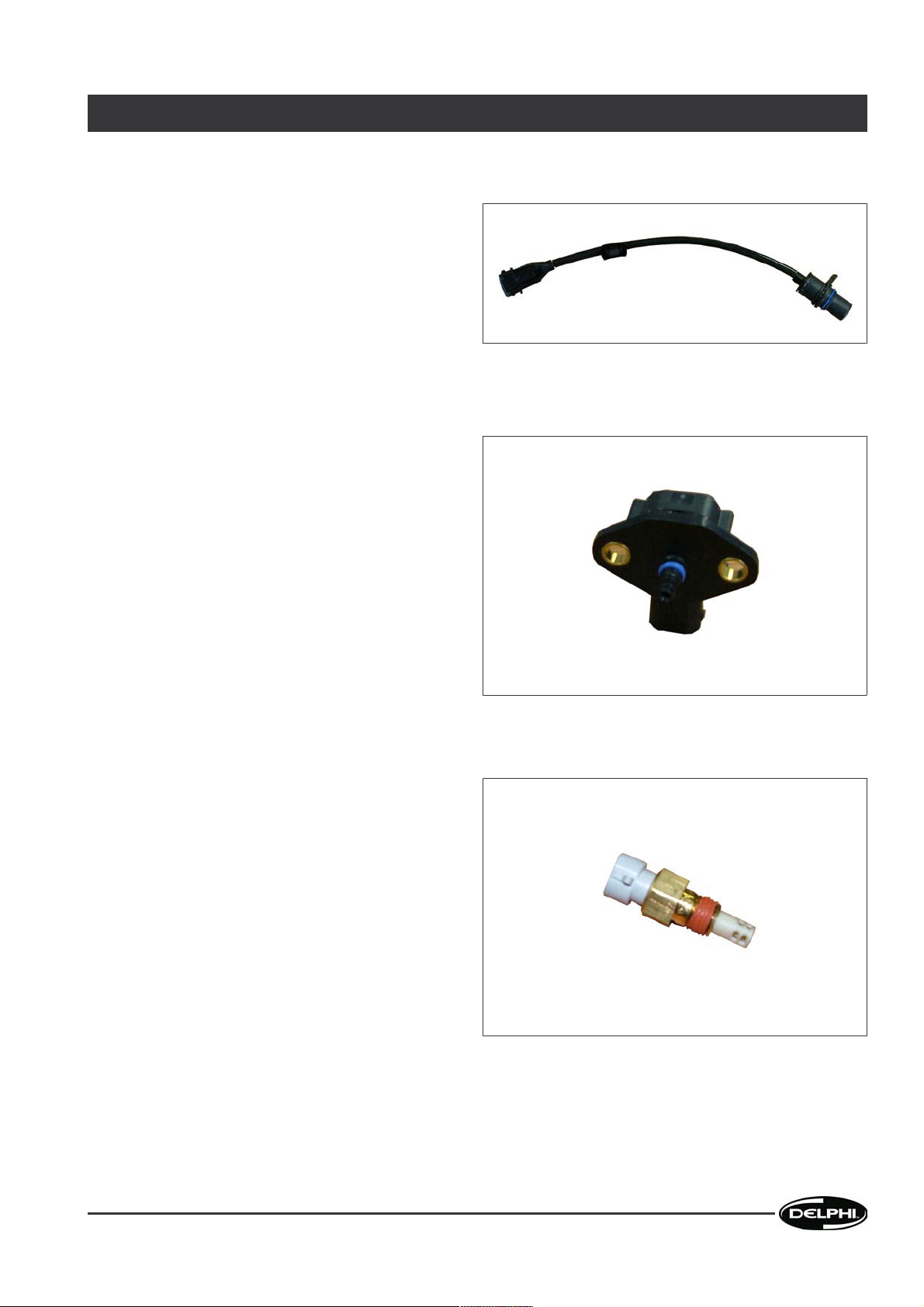
4.4.1 Crankshaft sensor
Specifications:
• Variable Reluctance sensor
• Speed Range: 50 – 3000 eRPM
• Voltage Range: 1.0V peak to peak min at
(50eRPM) to 250V Peak to Peak max @ 25°C
• Input Impedance - 10kΩ @ DC
To provide accurate crankshaft position
information to the ECU, for engine speed sensing &
fuel timing & quantity scheduling
I SP E CIA L FEA T URE S OF THE S YST E M
PARTS SUPPLIED BY DELPHI
4-8
DDNX300(EN) - Issue 1 of 09/2006
Page 15
4.4.2 Camshaft sensor
• Variable Reluctance sensor
• Speed Range: 50 – 3000 eRPM
• Voltage Range: 500mV peak to peak min (at
50eRPM) to 100V Peak to Peak max @ 25 °C
• Input Impedance - 10kΩ @ DC
To identify the cylinder number for firing the
electronic unit pump. Extra tooth located before Cyl.
No.1 as firing cycle initiation
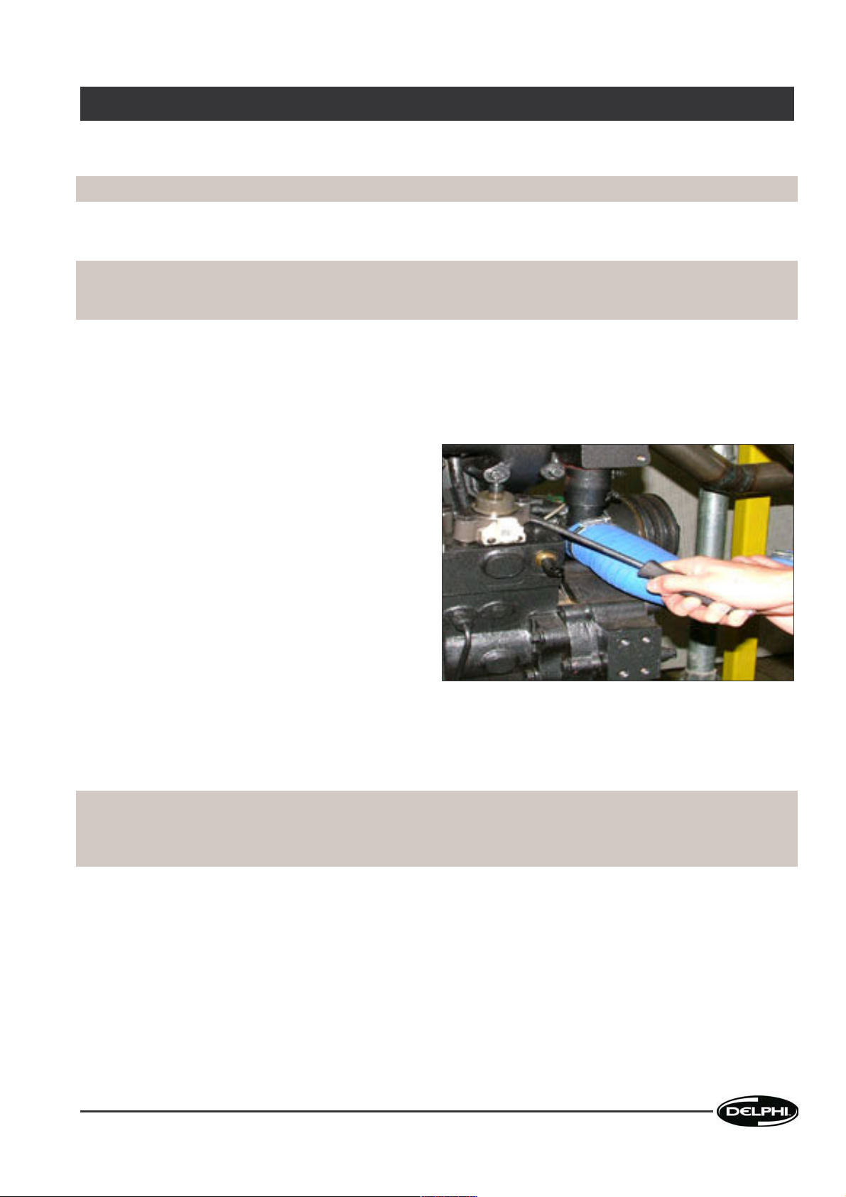
4.4.3 Boost pressure sensor
• Digital Sensor
• Voltage Range: 5V ± 0.25V DC
• Operating temperature -40°C to 125°C
• Operating pressure 50 to 300 kPa
Senses available boost pressure from
turbocharger. Is used by the ECU, along with boost
temperature to calculate air quantity available to
limit black smoke from excess fuelling quantity
4.4.4 Boost temperature sensor
• Thermistor Sensor
• Voltage Range: 5V ± 0.1V DC
• Operating temperature -40°C to 135°C
• Thermal time constant < 15 seconds
Senses boost temperature and is used by the ECU,
along with boost pressure, to calculate air quantity
available, to limit black smoke from excess fuelling
quantity
SPE C IAL F EAT U RES OF T H E S Y STEM I
PARTS SUPPLIED BY DELPHI
DDNX300(EN) - Issue 1 of 09/2006
4-9
Page 16

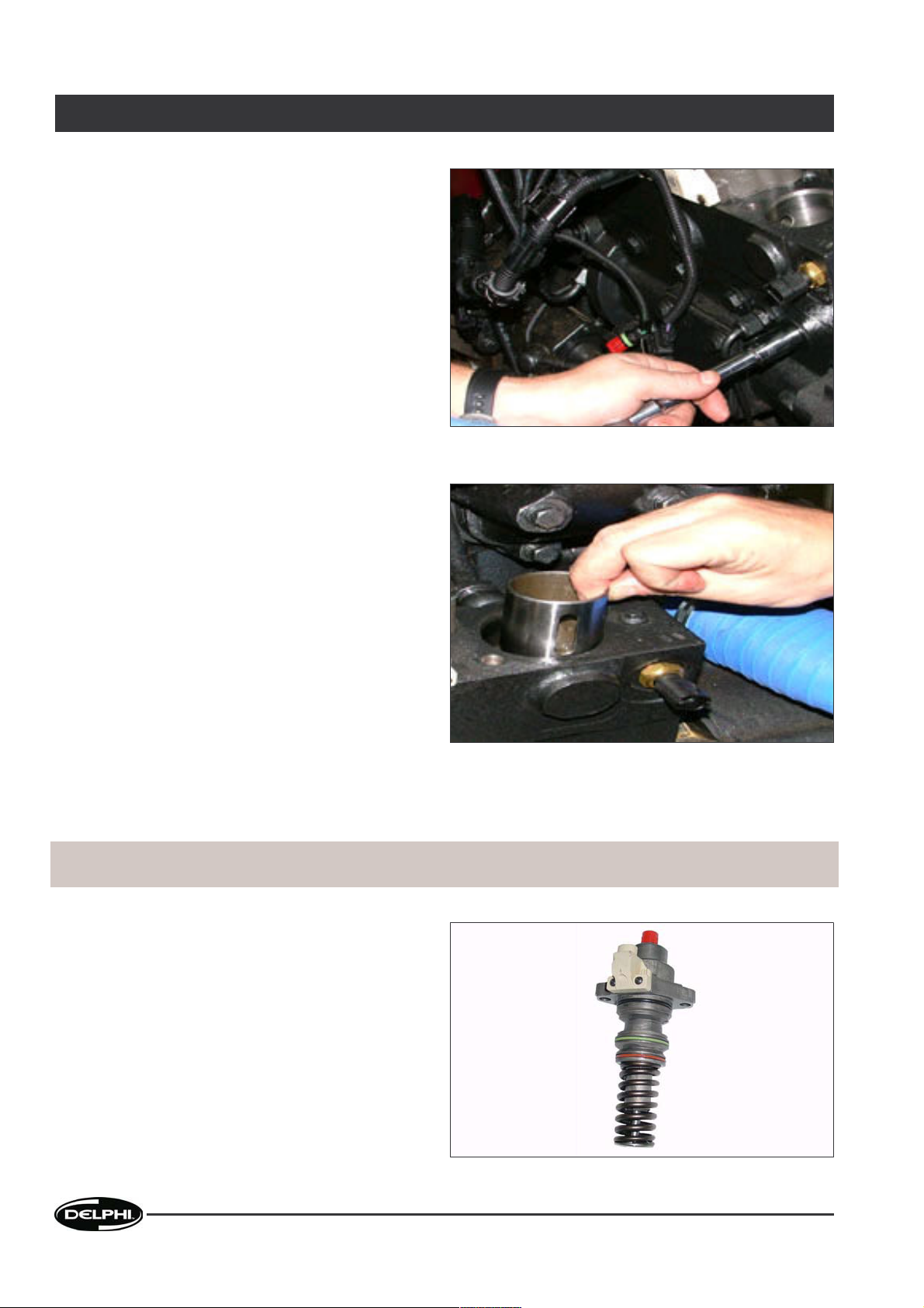
4.4.5 Coolant temperature sensor
• Thermistor Sensor
• Voltage Range: 5V ± 0.1V
• Operating temperature -40°C to 135°C
• Thermal time constant 8 seconds
The coolant temperature is used by ECU to
determine required engine cold-starting algorithm.
4.4.6 Fuel temperature sensor
• Thermistor Sensor
• Voltage Range: 5V ± 0.1V
• Operating temperature -40°C to 135°C
• Thermal time constant 8 seconds
The fuel temperature is used by ECU to calculate
required fuelling quantity offset according to
temperature of fuel in fuel manifold (due to fuel
density variation with temperature)
I SP E CIA L FEA T URE S OF THE S YST E M
PARTS SUPPLIED BY DELPHI
4-10
DDNX300(EN) - Issue 1 of 09/2006
Page 17

4.5 Engine Control Unit (ECU)
Specifications:
• Normal operating voltage: 9V - 31V
• 3 off 62 way Tyco cable connectors
The ECU controls the following functions:
• Injection fuelling and injection timing
• Voltage supply
• EGR (If applicable)
• System diagnostics
SPE C IAL F EAT U RES OF T H E S Y STEM I
PARTS SUPPLIED BY DELPHI
DDNX300(EN) - Issue 1 of 09/2006
4-11
Page 18

Page 19

5 PRELIMINARY OPERATIONS
The operations listed below will be required to gain access to the fuel injection system components, if any operations
are not appropriate it will be noted at the start of the relevant section.
5.1 Preparation
• Switch off the ignition and allow system to power down
• Prepare the tooling
• Prepare the plug kit
This operation is only required when removing/refitting the following components:
• High Pressure pipes
• Injectors
• Electronic Unit Pumps (EUP)
• Engine Control Unit (ECU)
• Electrical Sensors
REM O VAL / RE F ITT I NG I I
PRELIMINARY OPERATIONS
DDNX300(EN) - Issue 1 of 09/2006
5-13
Page 20

Page 21

6 HIGH PRESSURE PIPES
Important! Refer to the relevant cleanliness and safety instructions before starting work
6.1 Removal Of A High Pressure Pipe
Note: Carry out the preliminary operations - see section 1.1. Clean the high pressure pipe connector nuts using a solvent
(type CARECLEAN) applied using a clean brush. Clean the surrounding area to remove the dirt particles using a vacuum
cleaner (BLOVAC BV11 type)
Important! Immediately cap the injector and EUP high pressure pipe connections. Clean off any fuel to
prevent the risk of fire.
• Clean the connections with the pipe using the
solvent (type CARECLEAN) and vacuum any
contaminants from the high pressure junctions
using vacuum cleaner (BLOVAC BV11 type).
• Slacken the high pressure pipe nuts at both ends
whilst keeping the high pressure pipe in contact
with the injector and EUP. Ensuring the torque is
applied at the upper half of the nut to avoid
damaging it.
• Keeping the pipe nipple in contact with the injector
inlet with one hand, completely unscrew the nut
with the other, repeat operation for the pump
outlet.
• While maintaining the pipe nipple in contact with
either the pump or injector, vacuum any
contaminants from between the pipe and injector
or pump.
• Remove the high pressure pipe and discard.
• Once the pipe is removed, plug the exposed
orifices of the pump and injector to protect from
contamination.
Note: If a high pressure pipe has been removed, it MUST be replaced.
6.2 Refit Of A High Pressure Pipe
• Install the new high pressure pipe by placing the high pressure pipe nipples on to the injector and EUP.
• First tighten the high pressure pipe nuts by hand and then torque tighten them to a value of 28 Nm +/- 1 Nm. Torque
the injector connection first followed by the EUP connection.
Note: Apply the torque to the upper half of the high pressure pipe nut in order to avoid damaging it.
Note: The high pressure pipe MUST NOT be bent, as this could cause a leak.
REM O VAL / RE F ITT I NG I I
HIGH PRESSURE PIPES
DDNX300(EN) - Issue 1 of 09/2006
6-15
Page 22

Page 23

7 INJECTOR
Important! Refer to the relevant cleanliness and safety instructions before starting work
7.1 Removal Of An Injector
Important! Due to the possible presence of high pressure in the fuel tank, fuel may run into the cylinders
when removing the injectors. Therefore, when removing injectors always remove the fuel tank cap first.
Collect any fuel from the injectors. If it is necessary to remove an injector, it MUST be marked so that it
can be replaced in the same injector bore if it is to be reused and not replaced. It is recommended that all
dirt is removed from all the external parts before removal and refitting of engine components using the
Delphi special tool no. YDT205.
• Remove the rocker valve cover from the engine as
per the engine manufacturer instructions.
• Remove the valve rocker arms from the engine as
per the engine manufacturer instructions.
• Open the fuel tank cap to release the high pressure
of the fuel system.
• Remove the high pressure pipe as detailed in
section 2.1.
• Loosen and remove the injector inlet connector
(quill) securing nut from the side bore on the
engine.
• Remove the injector inlet connector (quill) from the
side of the cylinder head.
REM O VAL / RE F ITT I NG I I
INJECTOR
DDNX300(EN) - Issue 1 of 09/2006
7-17
Page 24

• Loosen and remove the injector clamp bolts and
remove the clamp.
• Screw a slide hammer into the injector removal
thread and carefully extract the injector ensuring
there is no side loading.
Note: 6112 engine: There may be a need to prize out the injector carefully and evenly under its clamping flange or
shoulder. Number injectors with its corresponding cylinder location.
• Carefully remove the copper sealing washer from the cylinder head, if washer is still in the bore or remove from
the injector.
• Clean the injector bore or all contaminants and then vacuum using a vacuum cleaner (BLOVAC BV11 type).
II R E MOV A L / R EFI T TIN G
INJECTOR
7-18
DDNX300(EN) - Issue 1 of 09/2006
Page 25

7.2 Refit Of An Injector
Important! New copper sealing washers and injector O rings MUST always be fitted when the injector is
refitted to the engine. New injectors are supplied complete with new copper sealing washers and O rings.
Take care not to add a second copper washer during installation.
Important! If during removal one or more copper sealing washers remain in the injector bore, the injector
would be reinstalled in a higher position. As a result fuel could be sprayed into the wrong part of the
combustion chamber which may lead to serious damage to the engine. Also there will be inadequate
sealing between the O-rings of the injector and the cylinder head. Fuel leaking from the injector could then
flow freely into the engine and dilute the lubricating oil. If an injector is showing signs of combustion due
to incorrect fitting do not reuse it.
• Please ensure cleanliness standards are met when
refitting the injector.
• Clean the injector well using tool YDT252. Position
the tool into the injector well and lowering the
centring device into the sleeve of the injector
holder. Turn the knob clockwise without pressing
on it. Remove and clean tool away from working
area.
• Clean the well and surrounding area of the cylinder
using the vacuum cleaner (YDT205) with the nozzle
attachment (YDT205).
• Remove the injector's protection caps.
• When refitting the old injector fit new O-rings (2)
and a copper sealing washer (1) to the injector.
Apply a little engine lubricating oil to both O-rings.
• Fit the injector back into the bore. Ensuring the
injector is correctly placed back into the bore,
making sure its located at the correct depth to allow
correct sealing.
Note: Injectors should always be fitted back into the same bore they were taken out from. If the inlet connector has
wear or damage on the sealing face it must be replaced.
• Refit the injector inlet connector (quill) into the bore in the side of the cylinder head by carefully aligning the ball
bearing on the top of the bore. Once in place, gently tap the end of the quill into the bore until it is securely located.
• Fit the injector clamp and tighten the bolt evenly and torque to a value of 23 Nm +/-1Nm.
• Tighten the injector inlet connector (quill) securing bolt to 40Nm +5Nm.
• Install the high pressure pipe (as detailed in
section 1.2) and torque tighten it to 28 Nm +/- 1 Nm.
• Refit the rocker cover and tighten to the specified torque as per the engine manufacturers manual.
• Refit the valve rocker arms to the engine and tighten to the specified torque as per the OEM workshop manual.
• Bleed the low-pressure fuel feed system (see
section 7.3).
REM O VAL / RE F ITT I NG I I
INJECTOR
DDNX300(EN) - Issue 1 of 09/2006
7-19
Page 26

7.3 Bleeding The Low Pressure Fuel System
• Using a hand primer (as supplied on the engine) bleed the low pressure fuel system by pumping the fuel.
• Collect the fuel from the highest part of the system using clear tubing.
• Continue to pump the primer until bubble-free fuel is seen at the fuel filter head and at the highest point in the lowpressure system.
II R E MOV A L / R EFI T TIN G
INJECTOR
7-20
DDNX300(EN) - Issue 1 of 09/2006
Page 27

8 SENSOR
Important! Refer to the relevant cleanliness and safety instructions before starting work
8.1 Removal Of The Sensor
Please refer to the vehicle's handbook and/or workshop manual for the location of each individual sensor
• Remove the connector from the sensor.
• Remove the sensor out of its location.
8.2 Refit Of The Sensor
• Refit the sensor into its location.
• Refit the connector onto the sensor.
• Tighten the sensor mounting bolts. Refer to
section 11.1 for torque settings.
REM O VAL / RE F ITT I NG I I
SENSOR
DDNX300(EN) - Issue 1 of 09/2006
8-21
Page 28

Page 29
9 ELECTRONIC UNIT PUMP (EUP)
Important! Refer to the relevant cleanliness and safety instructions before starting work
9.1 Removal Of The Electronic Unit Pump
Important! Perform the preliminary operations - see section 1.1. When removing the EUP, fuel will escape.
Collect this fuel to prevent the risk of fire. Dirt in the fuel system can lead to serious damage to the
electronic unit pumps and the pump housing.
Note: If it is necessary to remove an EUP, it MUST be marked so that it can be replaced in the same bore if it is to be
reused and not replaced. It is recommended that all dirt is removed from all external parts before removal/refit of engine
components using the Delphi special tool no. YDT205. To prevent dirt from entering the system, first clean the exterior
of the fuel tank around the filler cap.
• Open the fuel tank cap to release any pressure in
the fuel system.
• Disconnect the fuel supply and return pipes.
• If the fuel filter is high-mounted, unscrew the filter
cover a few turns to allow the fuel filter to empty,
collecting the fuel in a container.
• Open the connection to the pressure relief valve(s)
to allow the fuel to leave the fuel gallery.
• Remove the electrical connector from the EUP.
• Remove the high pressure pipe, as detailed in
section 2.1 and cap the EUP.
Note: The high pressure pipes may only be used once
and MUST be replaced after being removed.
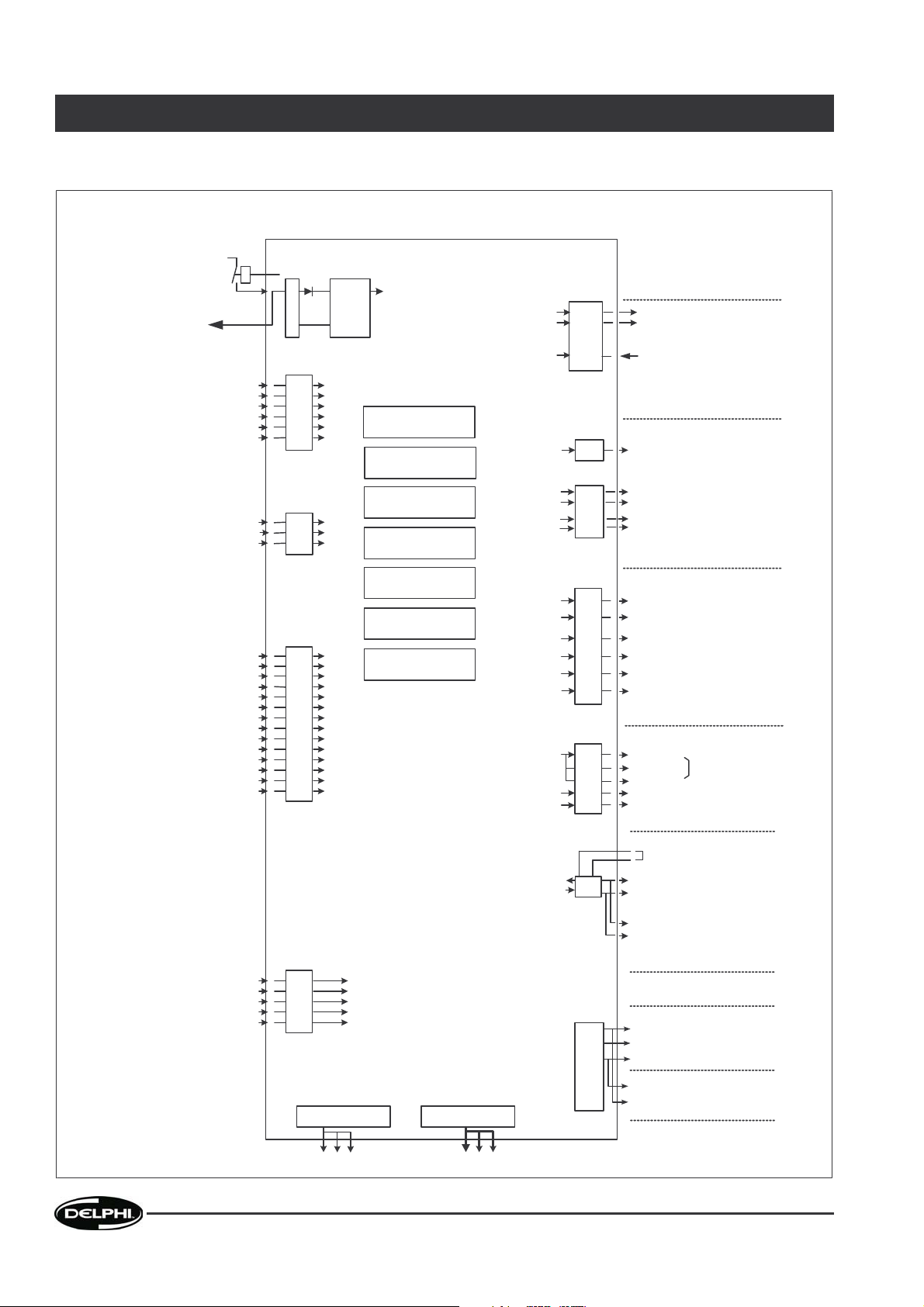
• The two EUP securing bolts should initially be loosened evenly and only by a few threads, and NOT fully removed.
If necessary prize the pump lightly and evenly (from both sides) upwards from under the flange (using the recesses
provided), with a screwdriver or suitable tool. Once the bolts take up the spring load again, continue loosening the
bolts evenly until the spring load is fully released then remove the bolts fully.
Important! If the EUP's securing nuts are fully removed the pump can suddenly release itself, causing
damage to the housing bores and even fracturing the pumping plunger. The EUP may be under spring
tension, depending on the position of the camshaft. If the EUP spring is under tension the engine must be
rotated until this tension is relived.
REM O VAL / RE F ITT I NG I I
ELECTRONIC UNIT PUMP (EUP)
DDNX300(EN) - Issue 1 of 09/2006
9-23
Page 30
• Carefully extract the EUP from the bore by hand,
avoiding side loading which could damage the
bore.
• Wrap the pump in a plastic bag and place it
carefully in a protective box.
• Remove the locating bolt from the cam box to
release the EUP tappet.
• Carefully remove the tappet from the engine by
hand.
9.2 Refit Of The Electronic Unit Pump
Important! If a new EUP is fitted into the engine the Trim Code, which is found on the solenoid connection
of the EUP body, MUST be entered into the ECU using the DIAMAND diagnostic tool.
• Remove the pump from the plastic bag.
• If using a new pump record the trim values of the
pump so the systems can be calibrated correctly.
• Replace the EUP O-rings, if refitting the EUP.
Note:
Top O-ring = Black
Middle O-ring = Violet (Older EUP's may have light
green O-rings)
Bottom O-ring = Brown
II R E MOV A L / R EFI T TIN G
ELECTRONIC UNIT PUMP (EUP)
9-24
DDNX300(EN) - Issue 1 of 09/2006
Page 31

• Replace the EUP body filter (filter to be specified).
• Refit the tappet into the cambox bore by hand, making sure that it aligns with the locating bolt.
• Refit the locating bolt and tighten. Refer to
section 11.1 for torque settings.
Note: Before the EUP is fitted, a small amount of engine oil must be applied to the O-rings. Depending on the position
of the Cam lobe the pump may sit proud of where it is supposed to be located. If this is the case, slightly tighten the
bolts one at a time until both bolts are fully torqued.
• Fit the EUP into the bore, by feeding it past the O-ring seal lead-in chamfers by lightly turning the pump to and fro.
Note: Take care not to tilt the pump during insertion as this can damage the engine or cambox bores.
• Hand tighten the two securing bolts evenly before applying a torque value of 60 Nm +/- 1 Nm.
• Re-fit the electrical connector.
• Install the high pressure pipe and torque tighten it to 28 Nm +/- 1 Nm, as detailed in
section 11.1.
• Bleed the fuel system (see
section 9.3).
• Use the DIAMAND diagnostic tool to configure the ECU using the Trim code recorded from the new pump.
Important! Please ensure to change the Trim value against the correct cylinder.
• Start engine and allow engine speed to stabilise.
• Use DIAMAND to erase any fault codes raised during the remove and refit procedure.
• Stop Engine.
• Check Trim codes are correct for the relevant cylinders only if new EUP is fitted.
9.3 Bleeding The Low Pressure Fuel System
• Using a hand primer (as supplied on the engine) bleed the low pressure fuel system by pumping the fuel.
• Collect the fuel from the highest part of the system using clear tubing.
• Continue to pump the primer until bubble-free fuel is seen at the fuel filter head and at the highest point in the lowpressure system.
REM O VAL / RE F ITT I NG I I
ELECTRONIC UNIT PUMP (EUP)
DDNX300(EN) - Issue 1 of 09/2006
9-25
Page 32

Page 33

10 DIESEL CONTROL UNIT (DCU) OR ELECTRONIC ENGINE CONTROLLER (EEC)
Important! Refer to the relevant cleanliness and safety instructions before starting work
10.1 Removal Of The Engine Control Unit
Please refer to the vehicle's handbook and/or workshop manual for the location of where the ECU is fitted on the vehicle.
• Remove the wiring support bracket bolts from the ECU body.
• Remove the three electrical unit connectors on the ECU.
• Remove the four mounting bolts that secure the ECU to the vehicle.
10.2 Refit Of The Engine Control Unit
Please refer to the vehicle's handbook and/or workshop manual for the location of where the ECU is fitted on the vehicle.
• Mount the ECU in its correct position, making sure that the earth strap makes a good contact with the vehicles body.
• Tighten the ECU mounting bolts evenly to 20 Nm +/- 1 Nm.
• Refit the three electrical unit connectors onto the ECU.
• Tighten the wiring support bracket bolts into the ECU body, taking care as these are self-tapping screws.
Note: When fitting to a new ECU the correct data for the engine derivative must be downloaded from the Diamand
diagnostic tool into the ECU, otherwise the engine will not be able to start or run.
REM O VAL / RE F ITT I NG I I
DIESEL CONTROL UNIT (DCU) OR ELECTRONIC ENGINE CONTROLLER (EEC)
DDNX300(EN) - Issue 1 of 09/2006
10-27
Page 34

Page 35

11 MISCELLANEOUS
11.1 Tightening Torques
Components to tighten Torque
High Pressure Pipes 28 Nm +/- 1 Nm
Injector Clamp Securing Bolts 23 Nm +/-1 Nm
Electronic Unit Pump Securing Bolts 60 Nm +/- 1 Nm
ECU Mounting Bolts 20 Nm
Crankshaft Sensor 7 - 10 Nm
Camshaft Sensor 7 - 10 Nm
Boost Pressure Sensor 6 Nm
Boost Temperature Sensor 20 Nm
Boost Temperature Sensor 22 Nm
Coolant Temperature Sensor 22 Nm
Fuel Temperature Sensor 22 Nm
Fuel Temperature Sensor 20 Nm
APP E NDIX III
MISCELLANEOUS
DDNX300(EN) - Issue 1 of 09/2006
11-29
Page 36

11.2 Resistance Values
Important! It is impossible to measure resistance less than 1Ω using a conventional multimeter.
Components Terminals Resistance values
Sensor ECU
Boost Pressure Digital Sensor J1-28
J1-30
N/A
Boost Temperature Thermistor J1-41
J1-42
J1-45
J1-46
2 kOhms ± 120 Ohms @ 25°C
Camshaft Sensor Variable
Reluctance
J1-53
J1-54
825 Ohms ± 100 Ohms @ 25°C
Coolant Temperature Thermistor J2-25
J2-26
2 kOhms ± 120 Ohms @ 25°C
Crankshaft Sensor Variable
Reluctance
J1-49
J1-50
825 Ohms ± 100 Ohms @ 25°C
Electronic Unit Pump N/A J1 - 3
J1 - 4
J1 - 7
J1 - 12
J1 - 11
J1 - 20
J1 - 15
J1 - 8
J1 - 19
J1 - 16
J1 - 23
J1 - 24
1.53 Ohms ± 10% @ 20°C
Fuel Temperature Thermistor J1-41
J1-42
J1-45
J1-46
2.75 kOhms ± 155 Ohms @ 25°C
III A PPEN DIX
MISCELLANEOUS
11-30
DDNX300(EN) - Issue 1 of 09/2006
Page 37

11.3 Tools
Special tooling from Delphi Delphi Reference
CR Tool kit YDT200
CR Vacuum cleaner YDT205
Injector well cleaning tool YDT252
CR Vacuum nozzle YDT255
DIAMAND diagnostic tool YDT300
Standard tooling (sourced locally) Reference
12 Point socket Facom R.5,5E - R.14E (or from similar supplier)
12 Point socket (12 mm) Facom J.7 - J.24 (or from similar supplier)
12 Point socket (17 mm) Facom J.7 - J.24 (or from similar supplier)
1/4 ratchet Facom R.161 (or from similar supplier)
3/8 ratchet Facom J.161 (or from similar supplier)
8 - 19 mm combination wrench Facom 40.8 to 40.19 (or from similar supplier)
Crowfoot socket (19 mm) Facom 18.10 - 18.19 (or from similar supplier)
Extension Facom J.210 (or from similar supplier)
Extension Facom J.210RC (or from similar supplier)
Extension Facom R.210 (or from similar supplier)
Torque wrench, 5 - 25 Nm Facom R.208-25 (or from similar supplier)
Torque wrench, 10-50 Nm Facom J.305DA (or from similar supplier)
Torque wrench, 10-50 Nm Facom J.208-50 (or from similar supplier)
Slide hammer Facom U.49L (or from similar supplier)
Parts, consumables and cleaning kit Reference
Clean container and brush Use suitable item
Cleaning solution Careclean type
Plug kit
APP E NDIX III
MISCELLANEOUS
DDNX300(EN) - Issue 1 of 09/2006
11-31
Page 38
11.4 Wiring Diagrams
14v (vsen)
Internal
ECU Temperature sensor
(PCB mounted)
Boost pressure
Fuel Pressure (reserved)
Reserved 1
Accel Pedal Sensor
Reserved 2
Boost Temp
Fuel Temp
Coolant Temp
Reserved 3
VCC
CAN1H
CAN1L
Preheat Drive
Exhaust Brake
ECU Power Relay
Engine Speed
Cooling Fan Relay
Inj Mon SCV (for development only)
Vehicle speed (reserved)
Cam sensor
Crank sensor
Unit pump (feed) 1, 3, 5
Unit pump (feed) 2, 4, 6
5A
(10A
peak)
INPUTS
Power Supply(VBAT)
Analogue Inputs
Switch Inputs
PWM Outputs (Low side)
Communication
Frequency /PWM Inputs
Sensor Supplies
Low side drives
Unit Pump Drives
OUTPUTS
Power Ground
CAN1
2 A
4 A
Reserved 1
Reserved 2
Key Sw
Door Saftey Switch
Clutch (reserved)
Service Start Switch
Reserved 1
Foot Brake (reserved)
Parking Brake (reserved)
Reserved 2
Idle Validation
Idle Trim Enable
Idle Trim Increment
Idle Trim Decrement
Exhaust Brake Request
Starter Motor (Optional)
High side drives
Electronic Unit Pump System
CAN1H
CAN1L
Case Ground
Switched Battery
Vehicle
connector
Links select for internal bus termination
1.5A
1.5A
Reserved 1
Reserved 2
2 A
2 A
2 A
2 A
2 A
1 A
9 Inputs
14 Inputs
3 Inputs
5 Outputs
2A
6 Outputs
3 Outputs
Ambient pressure sensor
(PCB mounted)
J1-30
J1-45
J3-33
J1-34
J1-41
J2-25
J3-44
J3-47
J3-36
J3-41
J3-24
J3-20
J3-16
J3-51
J3-32
J3-8
J3-7
J3-11
J3-12
J1-29
J2-5
J2-45
J1-53
J1-49
J3-48
J3-57,58,59
J1-40
J1-44
J2-24
J2-8
J2-32
J2-28
J3-2
J3-1
J2-16
J3-10
J2-60,61,62
J3-60,61,62
J1-25
J3-15
J3-23
J 1-62, 2-40, 3-5
5V (1)
5V (2)
5V (2)
5V (1)
5V (3)
1 A
J3-22
J3-2
3 Resistive
6 Ratiometric
J1-36
1.5A
1.5A
J1-48
Preheat Lamp
Hi Temp Lamp
Red Stop Lamp
Reserved 1
Reserved 1
J1-31
J3-9
All the same output drive
Unit pump (return) 1 - 6
AC Sw
J3-4
Vref1,2,3 Monitors
Internal
VBATT supply Monitor
Internal
50V supply Monitor
Internal
SCV I_sense monitor
Internal
PROTECTION
VOLTAGE
REGULATOR
Vehicle
connector
Engine
connectors
III A PPEN DIX
MISCELLANEOUS
11-32
DDNX300(EN) - Issue 1 of 09/2006
Page 39

PWM
Outputs
LSD
VBATT
+
_
2A
Pre-Heat
2A
Exhaust Brake
2A
2A
2A
Reserved 1
Reserved 2
Coolant Fan
Reserved 2
Reserved 3
Coolant
Temperature
NTC
0v
Sw Batt
P Batt
INJECTORS
J2
J1
J2-32
J2-28
J2-24
J3- 9
J1-31
J2- 8
J2-16
J2-6 (+)
J2-5
J2-7 (0v)
J2-46 (+)
J2-45
J2-43 (0v)
J2-25
J2-26
J2-57,58,59
J2-60,61,62
J1- 3
SCV 1
J1- 4
SCV 2
SCV 3
SCV 4
SCV 5
SCV 6
J1-15
J1- 8
J1- 7
J1-12
J1-19
J1-16
J1-11
J1-20
J1-23
J1-24
J1-34 (T)
J1-28 (+)
J1-30 (P)
J1-27 (0v)
J1-41 (T)
J1-42 (+)
J1-45 (P)
J1-46 (0v)
Boost
Pressure /
Temp
Fuel Temp
Reserved 1
Cam Sensor
Crank Sensor
Twisted
Pair,
optional
screen
HSD
Outputs
Reserved 1
Reserved (HSD)
Reserved 2
Preheat
Lamp
Hi Temp
Lamp
J1-33 (+)
J1-29
J1-26 (0v)
J1-60
J1-53 (+)
J1-54 (-)
P Batt
J1-61
J1-36
J1-35
J1-25
J1-40
J1-44
J1-48
J1-47
0V
J3
J3-24
J3-20
J3-16
J3- 4
J3-16
J3-47
J3-36
J3-51
J3-32
J3- 8
J3- 7
J3-11
J3-22
J3-48
J3-10
J3-34
J3-33
J3-37
J3-38
J3-41
5V
100k
J3-15 (H)
J3-23 (L)
PEDAL
Idle Validation
0v (or sen ret)
Twisted pair, -
CAN
communication
LSD
Outputs
Engine speed
RPM
2k8
15k
J3-1
J3-10
J3-44
Inj Mon SCV
Development
use only
Key Switch
5A Fuse
VBA
TT
Emergency Stop
Switch
15A Fuse
P
Batt
24v
0v
Case
Ground
J3- 2
J3-60,61,62
J3-57,58,59
Keyswitch
to uP
Relay hold
from uP
10R
3n9
10R
3n9
10R
3n9
Inj Mon SCV
Vehicle Speed
in (Res)
Red
Stop
Lamp
Diode >5A
>100v
Reserved 1
Reserved 2
Service Start Request
Parking Brake (Res)
Foot Brake (Res)
Clutch (Res)
Door Safety Switch
Exhaust Brake Request
AC Sw
Idle Trim Dec
Idle Trim Enable
Idle Trim Inc
VBATT
APP E NDIX III
MISCELLANEOUS
DDNX300(EN) - Issue 1 of 09/2006
11-33
Page 40

11.5 Abbreviations Used In This Manual
cc Cubic Capacity
DC Direct Current
°C Degrees Celsius
ECU Engine Control Unit
eRPM Engine Revolutions per Minute
EUP Electronic Unit Pump
kΩ Kilo Ohms
kPa Kilo Pascals
kW Kilo Watts
mm Millimetres
Nm Newton Meters
OEM Original Equipment Manufacturer
Trim Individual Electronic Unit Pump Correction
V Volts
III A PPEN DIX
MISCELLANEOUS
11-34
DDNX300(EN) - Issue 1 of 09/2006
Page 41

Whilst every care has been taken in compiling the information in this publication, Delphi Diesel Systems Ltd. cannot accept legal liability for any inaccuracies.
Delphi Diesel Systems Ltd. has an intensive programme of design and development which may well alter product specification. Delphi Diesel Systems Ltd.
reserve the right to alter specifications without notice and whenever necessary to ensure optimum performance from its product range.
All Rights Reserved
No part of this publication may be reproduced, stored in a retrieval system, or transmitted in any form, or by any means, electronic, mechanical, photocopying,
recording or otherwise, without the prior permission of Delphi Diesel Systems Ltd.
Il a été apporté une attention particulière pour garantir l'exactitude des renseignements contenus dans cette publication par Delphi Diesel Systems Ltd, mais
la société décline toute responsabilité légale à cet égard. Delphi Diesel Systems Ltd poursuit un programme intensif de conception et de développement qui
peut entraîner la modification des spécifications des produits. Delphi Diesel Systems Ltd se réserve le droit de modifier les spécifications, sans préavis et si
cela est nécessaire, pour assurer les performances optimales de sa gamme de produits.
Tous droits réservés
Toute reproduction, mémorisation dans un système informatique ou transmission sous quelle que forme que ce soit, ou par
tout moyen électronique, mécanique, par photocopie, enregistrement ou autre de cette publication est interdit sans
l'autorisation préalable de Delphi Diesel Systems Ltd.
Bei der Zusammenstellung der in dieser Veröffentlichung enthaltenen Informationen wurde mit größtmöglicher Sorgfalt vorgegangen. Delphi Diesel Systems
Ltd. kann jedoch rechtlich nicht für etwaige Ungenauigkeiten zur Verantwortung gezogen werden. Delphi Diesel Systems Ltd. führt ein fortlaufendes Designund Entwicklungsprogramm durch, weshalb es möglich ist, daß sich Produktdaten ändern. Delphi Diesel Systems Ltd. behält sich das Recht vor, ohne
Vorankündigung Spezifikationen jederzeit zu ändern, um die optimale Leistung seiner Produkte sicherzustellen.
Alle Rechte vorbehalten.
Kein Teil dieser Veröffentlichung darf ohne vorherige Genehmigung durch Delphi Diesel Systems Ltd. abgedruckt, in einem Datenverarbeitungssystem
gespeichert oder auf irgendeine Art und Weise, sei es auf elektronischem oder mechanischem Wege, durch Fotokopieren, Aufzeichnen oder auf sonstige Art,
übertragen werden.
Anche se ogni cura è stata adottata nel compilare le informazioni di questa pubblicazione, Delphi Diesel Systems Ltd. Declina qualsiasi responsabilità per eventuali
imprecisioni.
Delphi Diesel Systems svolge un intenso programma di progettazione e sviluppo che potrebbe modificare le specifiche del prodotto. Delphi Diesel Systems si riserva
il diritto di modificare le specifiche senza preavviso e ogniqualvolta lo ritenga necessario ai fini di assicurare le prestazioni ottimali dalla sua gamma di prodotti.
Tutti i diritti riservati
Nessuna parte di questa pubblicazione può essere riprodotta, memorizzata in un sistema elettronico o trasmessa in qualsiasi forma o con qualsiasi mezzo, elettronico,
di fotocopiatura, di registrazione o altro, senza la preventiva autorizzazione di Delphi Diesel Sistems Ltd.
Aunque hemos tomado todas las precauciones necesarias al recopilar esta publicación, Delphi Diesel Systems Ltd no acepta ninguna responsabilidad legal
por inexactitudes que puedan aparecer en la misma. En Delphi Diesel Systems Ltd se sigue un programa intensivo de diseño e investigación el cual podría
en cualquier momento alterar la especificación de los productos. Delphi Diesel Systems Ltd se reserva el derecho de alterar las especificaciones sin
notificación previa y siempre que esto sea necesario para asegurar el mejor funcionamiento posible de sus productos.
Todos los Derechos Reservados
No se permite copiar, almacenar en sistema recuperable ni transmitir esta publicación de ninguna forma o medio electrónico, mecánico, de fotocopia,
grabación o cualquier otro, sin autorización previa de Delphi Diesel Systems Ltd.
Ainda que se tenha lido o máximo cuidado na compilação da informação contida nesta publicação, a Delphi Diesel Systems Ltd, não pode aceitar qualquer
responsabilidade legal por inexactidões. A Delphi Diesel Systems Ltd. tem um programa intensivo de projecto e desenvolvimento que pode porventura alterar
as especificações do produto. A Delphi Diesel Systems Ltd. reserva o direito de alterar especificações sem aviso e sempre que seja necessario para
assegurar um desempenho óptimo da sua linha de produtos.
Todos os direitos reservados.
Nenhuma parte desta publicação pode ser reproduzida, armazenada num sistema de onde possa ser recuperada ou transmitida de alguma forma, ou por
quaisquer meios, electrónico, mecânico, de fotocópia, gravação ou outros, sem autorização antecipada de Delphi Diesel Systems Ltd.
 Loading...