

Page 1
DEUMIDIFICATORI / DEHUMIDIFIERS / LUFTENTFEUCHTER
DESHUMIDIFICATEUR / DESHUMIDIFICADOR
DE' LONGHI DH25 ECO
DATI TECNICI / TECHNICAL DATA / TECHNISCHE DATEN / DONNEES TECHNIQUES / DATOS TECNICO
Tensione / Voltage / Spannung / Tension / Tension V 220 .. 240
Frequenza / Frequency / Frequenz / Fréquence / Frecuencia Hz 5 0
Max.potenza assorbita / Max. input power / Max.Leistungsaufnahme W 42 0
Max.puissance absorbée / Max.potencia absorbida
Max acqua rimossa / Max moisture removed / Max Feuchtigkeitsentzug l / h 0.5 (*)
Humidité max éliminée / Humedad max eliminada
Aria trattata / Air treated / Luftumwälzung / Air traité / Aire tratado m3 / h 210 .. 300
Compressore / Compressor / Verdichter / Compresseur / Compressor Type SICOM
AE9415US
- avvolgimento / winding / Wicklung / bobinage / envolvimiento ru nW 6.86
avvolgimento / winding / Wicklung / bobinage / envolvimiento startW 25.5
- condensatore / capacitor / Kondensator / condensateur / condensador mF71
Umidostato / Humidostat / Feuchtigkeitsfühler / Indicateur d'humidité / Humidistato RH % 30 - 90
Antigelo / Antifrost / Frostschutz / Antigivre / Antihielo Type IMIT
- temperatura / temperature / Temperatur / température / temperatura ° C - 6 (off) / + 7(on)
Ventilatore / Ventilator / Ventilator / Ventilateur / Ventilador Type OLMO GA230T1723.01
-avvolgimento / winding / Wicklung / bobinage / envolvimiento (Nero / Marrone)W 245
(Nero / Blu) W 375
-corrente assorbita/input current/Stromaufnahme/courant absorbé/corriente assorbida A 0.22 (V Max.)
A 0.15 (V Min.)
Interruttore / Switch / Schalter / Interrupteur / Interruptor V /A 250 / 10
Microinterruttore / Microswitch / Microschalter / Microrupteur / Mincrointerruptor Type SAIA XGK2
Dati di pressione / Pressures data / Druck Daten / Caractéristiques de pression / Datos de presión
Type SICOM
Alta pressione / High pressure side / Hoher Druck / Haute pression / Alta presión ba r 25.3
Bassa pressione / Low pressure side / Niedriger Druck / Basse pression / Baja presión ba r 6.5
Carica di gas / Gas charge / Gas Menge / Quantité du Gas / Carga de Gas (R290) gr 150
* A condizioni standard 27°C - 60% U.R. / Under standart conditions of 27°C - 60% R.H.
A conditions standard 27°C - 60% H.R./Bei Standard-Betriebsbedingungen von 27°C,
60% rel. Luftfeuchtigkeit / En condiciones estándar 27°C - 60% H.R.
R 290
Gas ecologico / Ecological gas
1
De'Longhi
SCHEDA TECNICA ST 0912 / 2001
Page 2
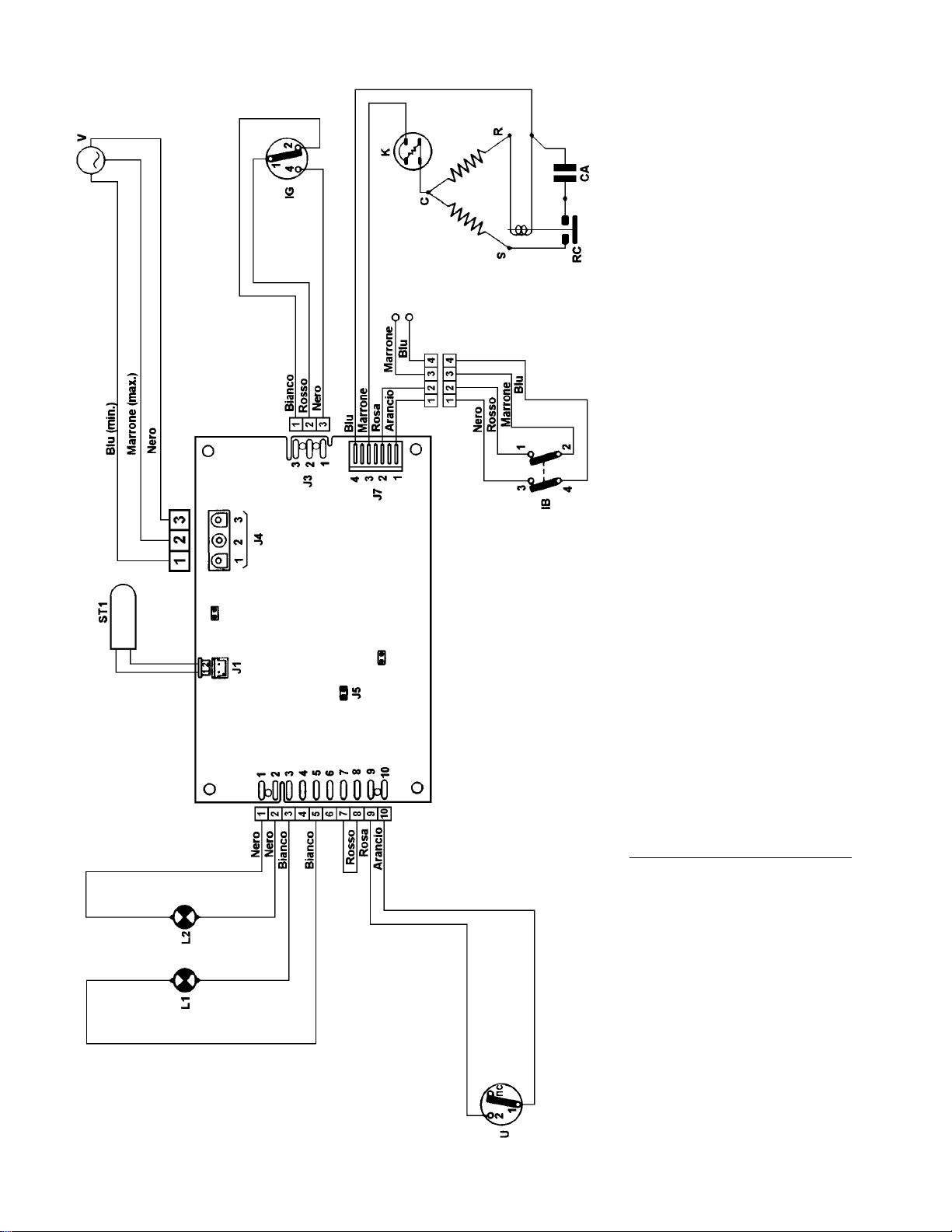
SCHEMA ELETTRICO / ELECTRICAL DIAGRAM / SCHALTPLAN
SCHEMA ELECTRIQUE / ESQUEMA ELECTRICO
M
SA
(ROSSO)
(BLU)
RT1
RT2
LEGENDA LEGEND ZEICHENERKLÄRUNG LEGENDE LEGENDA
CA Condensatore CSR Capacitor CSR Kondensator CSR Condensateur CSR Condensador
CSR Compressore Compressor Verdichter Compresseur Compressor
DV Deviatore min/max. min/max changeover switch min/max Kühl Umschalter Commut. min/max Commutador min/max
IB Interruttore generale Main switch Hauptshalter Interrupteur gènèral Interruptor generale
IG Microinterruttore Microswitch Microschalter Microrupteur Microinterruptor
K Klixon Comp.protector Verdich.Uberlastschalter Protecteur comp. Protector del Compressor
L1 Spia alarme Alarm warnig light Alarm Kontrolleuchte Voyant de alerte Piloto de alarma
L2 Spia tanica piena Full tank warning light Alarm "Tankvoll" Voyant resérvoir plein Piloto de depòsito llno
RT1 Sonda ambiente Temperature probe Temperatur-Sonde Sonde de temperature Sonda de temperature
RT2 Sonda sicurezza Sicurity probe Sicherheitsfühler Sonde de sécuritè Sonda seguridad
RC Relè Relay Relais Relais Relais
ST1 Antigelo Antifrost Frostschutz Antigivre Antihielo
SA Basetta elettronica Electronic boart Elektronische Platine Fiche électronique Ficha electronica
U Umidostato Humidostat Feuchtigkeitsfühler Indicateur d'humidité Medidor de humidad
V Ventilatore Ventilator Ventilator Ventilateur Ventilador
COLORI COLOURS FARBEN COULEURS COLORES
Arancio Orange Orange Orange Anaranjado
Bianco White Weiß Blanc Blanco
Blu Blue Blau Bleu Azul
Marrone Brown Braun Marron Castano
Nero Black Schwarz Noir Negro
Rosa Pink Rosa Rose Rosa
Rosso Red Rot Rouge Rojo
Verde Green Grün Vert Verde
2
SCHEDA TECNICA ST 0912 / 2001
Page 3
IMPORTANT ADDITIONAL INFORMATIONS
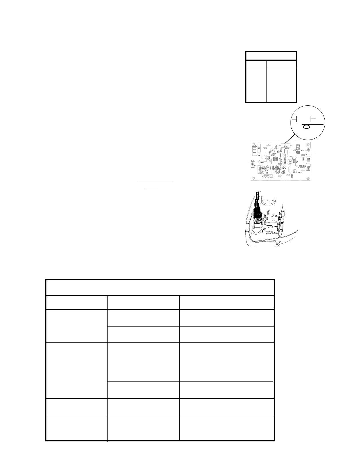
ELECTRONIC BOARD (SA)
This is the control board of the dehumidifier that along with the probe ST1 and the two sensors RT1 and RT2, verifies the
working conditions of the appliance itself. In case of missing information (e.g. a defective probe), the board will stop the
appliance and the alarm light will stay steady on.
ANTIFROST PROBE (ST1)
This probe is located on the aspiration tube of the compressor, where it mesaures
the gas temperature. With gas temperatures below -6°C, the electronic board sets
the appliance on antifrost function. The compressor will stop and the blu alarm light
blinks fast. When the gas temperature has risen again to above +7°C the appliance
resume dehumidifying.
AMBIENT SENSOR (RT1)
This sensor measures the ambient temperature.
SECURITY SENSOR (RT2)
This sensor is located at 1mm. from the resistance R19.
Confronting the temperature readings from RT1 and RT2, the microprocessor of
the electronic board can detact a malfunction of ventilation and change the
ventilator speed and if needed eventually stops the appliance in alarm mode.
INSTRUCTIONS FOR MAINTENANCE ON ELECTRONIC BOARD
When you replace the electronic board, do make sure that the distance between the
sensor (RT2) and the resistance (R19) is 1mm.
INSTRUCTIONS FOR MAINTENANCE ON THE ON/OFF SWITCH
For spark protection the ON/OFF switch is surrounded by a heat shrinking sleeve,
which ones removed or damaged is not to be reused or to be repaired.
PROBE VALUES
°C K
WW
W±5%
WW
-5 2352
0 1766
+10 1018
+15 781.4
+25 470
R19
RT2
ñ
ñ
0.8 mm
Having to exchange the ON/OFF switch you therefor have to exchange the
control-panel complete with switch, wires and spark-protection.
INFORMATION ON THE VENTILATOR
The ventilator has only one working speed, but automatically it is forced
on a slower speed during the 3 minutes compressor delay phase or when
problem on the normal working function.
ALARM MODES
TYPE OF ALARMS CAUSES EFFECT
ANTIFROST ALARM AMBIENT HUMIDITYAND/OR THE COMPRESSOR STOPS.
VENTILATOR ALARM THE NORMAL VENTILATOR THE COMPRESSOR REMAINS ON.
TEMPERATURE TO LOW
ANTIFROST PROBE THE COMPRESSOR STOPS.
BROKEN OR DETACHED
SPEED DOES NOT WORK THE VENTILATOR WORKS FORCED
VENTILATOR DOES NOT THE COMPRESSOR STOPS.
WORK
BLU ALARM LIGHT BLINKS FAST.
BLU ALARM LIGHT IS STEADY ON.
ON A LOWER SPEED.(SEE INFO
ON VENTILATOR ABOVE)
BLU ALARM LIGHT IS STEADY ON.
BLU ALARM LIGHT IS STEADY ON.
FULL TANK ALARM CANISTER FULL OF WATER THE COMPRESSOR STOPS.
3 MIN. COMPRESSOR SAFETY DELAY FOR THE THE COMPRESSOR IS OFF.
DELAY COMPRESOR
OR OUT OF ITS SITE
RED PILOT LIGHT IS ON.
GREEN ALARM LIGHT BLINKS SLOWLY
FOR 3 MINUTES
WHILE THE COMPRESSOR STARTS.
THEN GOES OFF
3
SCHEDA TECNICA ST 0912 / 2001
Page 4

INFORMATIONS ABOUT ECOLOGICAL REFRIGERANT R 290
WHY USING A NEW REFRIGERANT?
As we know well, the distruction of the Ozone layer, is also caused by the emission of CFC and HCFC. Scientists
have warned society, by some time so far, about the danger of an unfiltered ultraviolet radiation for mankind.
After years in which the public opinion became more and more conscious about this problem, the industry
committed itself to take the environment damaging refrigerants off the market and to replace them with
environmental friendly ones.
In a first step, which regarded the refrigeration, the most environment damaging refrigerant R12 had been replaced
by the R134a. While the Ozone Depletion Potential (ODP) of R134a is 0, it still has a relatively high Global
Warming Potential (GWP). As the Greenhouse Effect gains more and more attention, the industry turned its
interest towards the hydrocarbons.
For some time now, in refrigerators has been used the ISOBUTANE or better R600a.
But for air conditoners thought, it was necessary to find a substitute, which respected the cooling characteristics
of R22. For this reason DE'LONGHI in some of its air conditioners and dehumidifiers models, has introduced the
R290. It has quite the same refrigeration characteristics of the R22 and is 100% environmental friendly.
SIGNS OF RECOGNITION
You can easely recognize DE'LONGHI air coinditioners and dehumidifiers working with R290, by the green
coloured Rating label. There are stated the gas type, the gas quantity and the warning symbol to indicate the
inflammability of the gas. Another sign of R290 being used is found on the service pipe of the compressor.
IMPORTANT DIFFERENCES BETWEEN THE REFRIGERANTS
CLASSIFICATION OF THE GASSES
According to their characteristics, all refrigerants are classified by a letter and a number combination. The letter
declares the toxicity of the gas (A = non toxic - B = toxic) while the number stands for the inflammability (1 =
nonflammable; 2 = low inflammability; 3 = high inflammability).
R22 is classified by A1 (non toxic - nonflammable)
R290 is classified by A3, non toxic but high inflammability.
ATTENTION: R290 is absolutely colourless, odourless and tasteless. Its presence cannot be recognized
by human senses.It is heavier than air and concentrates at the ground.
GENERAL CHARACTERISTICS
In the refrigerant circuit, both gasses behave almost the same way. For this reason the values of temperature and
pressure of models using R290, are the same as those in models using R22.
However, Service procedures are quite different in the two cases (as specified below)!
Important: The R290 which DE'LONGHI uses on its air conditioners and dehumidifiers, has a purity of 99,5%.
If, for the refilling process, a gas with this purity grade should not be available, you can use R290 gas which has
a purity till 99%.
Gas with a lower purity grade could damage important components of the air conditioner and has not
to be used.
At this stage, on machines working with R290, we use only reciprocating types compressors .
REPAIRS
Because of the high inflammability of R290, repair works on the refrigerant circuit of
and
ECO DEHUMIDIFIERS
precautions.
In order to avoid any unnecessary risk and to obtain a good repair result you will have to strictly follow
the described guidelines.
, differs from repair works on traditional ones, expecially for what concerns safety
4
SCHEDA TECNICA ST 0912 / 2001
ECO AIR CONDITIONERS
Page 5

SPECIAL TOOLS
- Explosionproof vacuum pump.
- Gasdetector for hydrocarbons.
- Electronic balance with less than five gramm tolerance.
- LOCKRING plier.
- Gas bottle homologated for propan gas and operable with the balance.
SAFETY PRECAUTIONS
Before starting any intervention on the refrigerant circuit of
DEHUMIDIFIERS
- Do not smoke.
- Do not work close to sources of heat or open flames.
- Avoid any formation of sparks (example: use of Vacuum cleaners, switches or anything causing discharges
of static electricity).
- Secure a sufficient room volume and air ventilation.
- Do not only take care of yourself but also of other people in the same room!
- You are obligated furthermore to observe all safety rules regarding transport and working with
highly inflammable gasses of your country and/or syndicate.
, you have to follow the described SAFETY PRECAUTIONS:
DE'LONGHI ECO AIR CONDITIONERS and ECO
OPENING THE REFRIGERANT CIRCUIT
To open the refrigerant circuit do never use tools which could cause sparks like ex. saws. Furthermore
it is not allowed to unweld the tubes of the compressor. The last is also valid for the air conditioner or
dehumidifier already emptied of its gas charge!
A. For repairs because of gas losses and leakages
Connect a piercing plier with a long discharge tube, whose end you hang out to an open air space. Make sure
that the tube cannot move and all gas will be discharged into open air. Pierce the compressor service pipe close
to the pressure seal (at the compressor side of it) and let all the gas discharge through the tube. Cut now the service
pipe using a tube-cutter.
B. For repairs because of system blockage (example: Capillary tube)
In case of a blockage of the refrigerant system, the gas trapped between blockage and compressor cannot be
discharged through the service pipe. If you have even the slightest impression that this might be your case
(example the customer complained about the regular intervention of the pressure switch or high power
consumption with none or little cooling), you will have to pierce also the high pressure tube between the block and
the compressor. Do this as close as possible to where you have diagnosticed the block (example: if the capillary
tube is blocked, than pierce the tube before the filter)
Before the conditioner is ready for repair work, you have now to clean the system off all possible
remaining gas.
CLEANING THE REFRIGERANT CIRCUIT.
After the natural discharge of the gas through piercing plier and discharge tube, there is still a considerable amount
of gas in the tubes and in the oil of the compressor. This gas has to be removed before doing any repair work. In
order to do so, connect the explosionproof vacuum pump to the service pipe and, only in case of a system
blockage, also to the high pressure side of the compressor.
Discharge the outcoming gas always into an open-air space!
Let the vacuum pump produce a good vacuum. Close now the valves of the 4 way manifold and stop the vacuum
pump. Start the compressor for about 15 to 20 seconds and repeat the vacuum procedure.
Only now you are allowed to weld on the air conditioner or dehumidifier in order to replace faulty components or
to close leakages.
The only exceptions are the connections of the tubes to the compressor. R290 has a high ability to react with
the oil of the compressor. The heat of the welding could set free further amounts of gas with an high risk of fire.
Therefore, close to the compressor no welding is allowed.
5
SCHEDA TECNICA ST 0912 / 2001
Page 6

In case of leakage close to the compressor or a compressor breakdown, follow the following procedure.
Disconnect the compressor using a tube cutter. Do this as close as possible to the compressor. Once the
compressor has been removed, you can do any type of maintenance (extend tube or unweld pieces and so on).
The new compressor, which has not been charged with R290 yet, can be welded into the system as usual.
If you have only to extend the compressor service pipe, you can do this using a LOCKRING CONNECTOR.
PREPARATIONS FOR THE VACUUM
Once you have closed the leakage and exchanged faulty components, you can prepare the refilling unit.
Carefully follow these steps:
- Verify that the service pipe is long enough to allow you to close it after the refilling procedure. Bear in mind that
you have to squeeze it (in case you do not have a "Ball like Pinch Off Tool" you will have to squeeze it twice)
and you have to seal it with a LOCKRING SEAL. If you need to extend the service pipe, you have to do it
now.
- Connect the service pipe with a gas-tap, (valve E), and then to the 4 way manifold valve "C".
- Connect the vacuum pump to the manifold valve "A" and the gas bottle to valve "B".
Important: The tube connecting gas bottle and manifold has to be long enough that it can rest onto the floor or
table when the gas bottle is positioned onto the balance, otherwise it could greatly vary the measurement.
- Position the balance close to the air conditioner or dehumidifier and secure the gas bottle upside down onto it.
PUMPING THE VACUUM AND REFILLING
- Secure yourself, that all valves are closed.
- Open valve "E" of the servicepipe and the valves "A,B and C" of the 4 way manifold. This way, the pump will
produce a vacuum in the whole unit, up to the closing valve of the gas bottle.
- Switch on the vacuum pump and let it produce a good vacuum.
- When the vacuum has reached a good value, close the valve "A" towards the vacuum pump and switch it off.
Check that the unit will keep the vacuum.
- Now close the valve "E" at the compressor service pipe.
- Open the valve of the gas bottle "F" and let the liquid gas fill the refilling unit until the closing valve of the service
pipe "E".
- Once the gas has filled the unit, do a last check that everything is at its place, then reset the balance.
After you have reset the balance, you are not allowed to touch or move the gas bottle and filling
tubes, as this would upset the measurement of the balance. The balance has to stay stable before
opening the valve "E" and allowing the gas to fill the air conditioner or dehumidifier.
- Open slowly the valve "E" at the service pipe and let the needed gas quantity enter into the air conditioner or
dehumidifier, plus additional three gramms (*).
Keep in mind, that the tolerance for the refilling is of five gramms.
In case that not all gas enters into the air conditioner or dehumidifier, close valve "E", start the compressor and
carefully add the gas until the right amount has entered the system.
- Close all valves.
- Let the gas in the filling tubes escape into open air and proceed to the closure of the refrigerant system.
In case that the tubes have been moved, the gas bottle has run out of gas or other problems, you will have
to repeat the vacuum and filling process.
(*) Tests in the laboratory have resulted in a small difference between the gas quantity indicated by the balance
and which actually entered into the refrigerating system. To improof the repair result, we therefore recommend to
add three gramms to the gas quantity indicated by the technical notes and rating plate.
6
SCHEDA TECNICA ST 0912 / 2001
Page 7

CLOSURE OF THE REFRIGERANT SYSTEM
To close the refrigerant system, proceed as follows:
- squeeze the service pipe with a Ball Pinch Off Tool, which garantees you a 100% closure of the service pipe.
Squeeze the pipe towards its end, without deforming it. In fact you will need at least ca. 1 cm. undeformed
pipe in order to seel it with LOCKRING SEAL. If you do not have this ball Pinch Off Tool, you can use a normal
one, squeezing the pipe two times with ca. 2 cm distance from one point to the other. Let the Pinch Off Tool
onto the last squeezing point until you have sealed the pipe off.
- Remove the coupler and valve from the service pipe.
- Seal the service pipe with a LOCKRING SEAL.
ATTENTION: All Lockring Connections of the air conditioner or dehumidifier, have an inner diameter of 6mm.
To apply LOCKRING CONNECTORS OR SEALS observe all LOCKRING INSTRUCTIONS.
- Switch on the unit and let it run for at least 15 minutes.
- Using the gas detector, carefully check the unit for gas losses, check in particular the closure of the service
pipe.
THE REFILLING UNIT
Discharge tube to the open
Compressor with
Service pipe and
valve
E
Vacuum pump
C
4 Way Manifold
A
B
Gas bottle
with valve
F
Balance
D
A - Valve to vacuum pump
B - Valve to gas bottle
C - Valve to compressor Service pipe
D - Connection to empty the high pressure side in case of system blockage
E - Coupler with valve at compressor service pipe
F - Valve of gas bottle
7
SCHEDA TECNICA ST 0912 / 2001
 Loading...