

Page 1
DEUMIDIFICATORI / DEHUMIDIFIERS / LUFTENTFEUCHTER
°C
°C
°C
0
5.48
0
8.066
DESHUMIDIFICATEUR / DESHUMIDIFICADOR
DE’LONGHI DE 220
(INT)
DATI TECNICI / TECHNICAL DATA / TECHNISCHE DATEN
DONNEES TECHNIQUES / DATOS TECNICOS
Tensione / Voltage / Spannung / Tension / Tension V 220 … 240
Frequenza / Frequency / Frequenz / Fréquence / Frecuencia Hz 50
Max.potenza assorbita / Max. input power / Max.Leistungsaufnahme W 370
Max.puissance absorbée / Max.potencia absorbida
Max acqua rimossa / Max moisture removed / Max Feuchtigkeitsentzug l/h 0.5*
Humidité max éliminée / Humedad max eliminada
Aria trattata / Air treated / Luftumwälzung / Air traité / Aire tratado m3/h 210 / 300
Compressore / Compressor / Kompressor / Compresseur Type SICOM ELECTROLUX
Compressor AE9415US L57TN
- avvolgimento / winding / Wicklung / bobinage / envolvimiento runΩ 6,73 8,15
- avvolgimento / winding / Wicklung / bobinage / envolvimiento startΩ 25,8 38,0
- condensatore** / capacitor** / Kondensator** µF - - (none) 47-56
- condensateur** / condensador** (integrated into
- PTC/ PTC / PTC / PTC / PTC Ω 4–26 (at 20°C) compressor)
Umidostato / Humidostat / Feuchtigkeitsfühler RH % 20 - 100
Indicateur d'humidité / Humidistato
Termostato / Thermostat / Thermostat / Thermostat / Termostato °C 0 (±5) / -39 (±3)
Antigelo / Antifrost / Frostschutz / Antigivre / Antihielo Type Elettronico
- temperatura / temperature / Temperatur / température / temperatura Off/On °C -5 - +2
Ventilatore / Ventilator / Ventilator / Ventilateur / Ventilador Type ELCO NE-060-001
- avvolgimento / winding / Wicklung / bobinage / envolvimiento (Brown-Black)Ω 130
(Blue-Black) Ω 245
- corrente assorbita / input current / Stromaufnahme A 0,15 / 0,22
- courant absorbé / corriente assorbida
Microinterruttore / Microswitch / Microschalter / Microrupteur Type / V / A Saia XGK6 / 250 / 12
Mincrointerruptor CROUZET F83163.056 / 250/12
Commutatore / Commutator / Funktionswahlschalter / Selecteur / Commutador V / A 250 / 16
Dati di pressione / Pressures data / Druck Daten / Caractéristiques de pression / Datos de presión
Alta pressione / High pressure side / Hoher Druck / Haute pression / Alta presión bar 16.1*
Bassa pressione / Low pressure side / Niedriger Druck / Basse pression / Baja presión bar 4.8*
Carica freon / Freon charge / Freon Menge / Quantité du Fréon / Carga de freon (R22)gr 230 (ELECTROLUX)
255 (SICOM)
VALORI DELLA SONDA NTC / VALUES OF THE NTC-PROBE WERTE DER NTC-SONDE /
°C ΚΩΚΩ °C ΚΩΚΩ °C ΚΩΚΩ
-10 37.33 5 17.21 20 8.49
- 5 28.61 10 13.5 25 6.8
22.11 15 10.67 30
VALEURS DE LA SONDE NTC VALORES DE LA SONDA NTC
IMIT ICA
ΚΩΚΩ
-10 55.581 5 25.521 20 12.489
- 5 42.965 10 19.943 25 10
32.956 15 15.718 30
ΚΩΚΩ
ΚΩΚΩ
* A condizioni standard 27°C - 60% U.R. / Under standart conditions of 27°C - 60% R.H. / A conditions standard 27°C - 60% H.R
Bei Standard-Betriebsbedingungen von 27°C, 60% rel. Luftfeuchtigkeit / En condiciones estándar 27°C - 60% H.R.
** Se previsto / ** If provided / ** Wenn vorgesehen / ** Se prévu / ** Se previsto
SCHEDA TECNICA 99045
Page 2
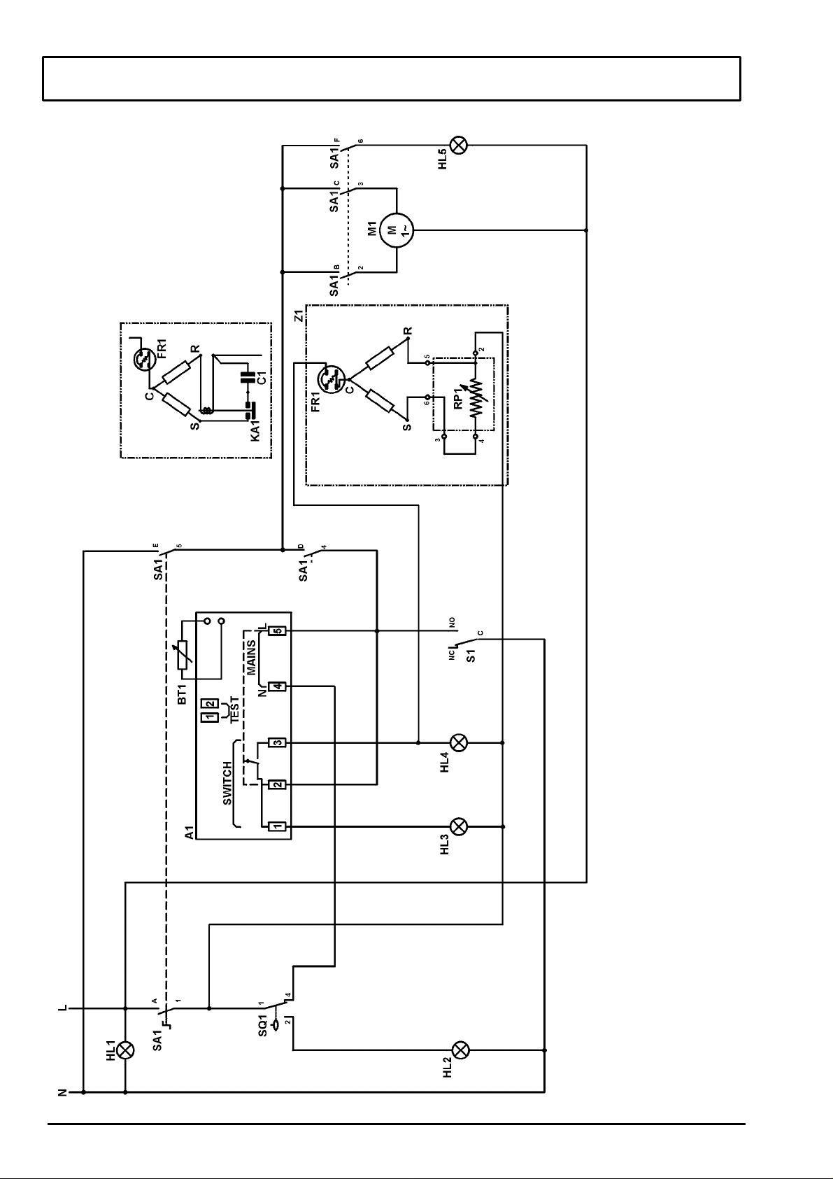
SCHEMA ELETTRICO / ELECTRICAL DIAGRAM / SCHALTPLAN
Microinterruptor nivel de agua
Piloto de alarma antihielo
Piloto de desumidificación
Piloto de ventilación
Piloto de calefación
Medidor de humidad
Commutador
Microinterruptor nivel de agua
Compressore
Microrupteur niveau de l'eau
Voyant déshumidification
Voyant de ventilation
Voyant de chauffage
PTC Relais
Indicateur d'humidité
Selecteur
Microinterrupteur neiveau de l'eau
Compresseur
Netzspannung Kontrolleuchte
Tank-voll Kontrolleuchte
Kontrolleuchte "Abtauen"
Kontrolleuchte "Entfeuchten"
Ventilation Kontrolleuchte
Heizbetrieb Kontrolleuchte
PTC Relais
Feuchtigkeitsfühler
Funktionswahlschalter
Wasserniveau-Mikroschalter
Kompressor
Defrosting control lamp
Dehumidification control-lamp
Ventilation control lamp
Heating control lamp
PTC Relay
Humidostat
Funtion changeover switch
Water tank microswitch
Compressore
Spia deumidificazione
Spia riscaldamento
Umidostato
Commutatore funzioni
Microinterruttore tanica
Compressore
A1
BT1C1FR1
HL1
HL2
HL3
HL4
HL5
HL7
KA1M1RP1S1SA1
SQ1
Z1
SCHEMA ELECTRIQUE / SCHEMA ELECTRICO
\
Legenda
Ficha antihielo
Sonda antihielo
Condensador Z1
Protector Z1
Piloto alimentación
Relè
Ventilador
Relè PTC
Legende
Fiche antigrivre
Sonde antigrivre
Condensateur Z1
Protecteur Z1
Voyant alimentation
Voyant de degivrage
Zeichenerklärung
Elektron. Frostschutz
Frostschutzsonde
Kondensator Z1
Kompressorschutz
Legend
Antifrost board
Antifrost probe
Z1 capacitor
Thermal protector Z1
Power fed control lamp
Tank full warning light
Relais
Ventilateur
Relais
Ventilator
Relay
Ventilator
Legenda
Scheda antigelo
Sonda antigelo
Condensatore Z1
Protettore Termico Z1
Spia alimentazione
Tanica piena
Spia antigelo
Spia ventilazione
Relè
Ventilatore
Relè PTC
2 SCHEDA TECNICA 99045
Page 3

SCHEMA ELETTRICO / ELECTRICAL DIAGRAM / SCHALTPLAN
Viola Violet Violett Violet Viola
SCHEMA ELECTRIQUE / SCHEMA ELECTRICO
Colori Colours Farben Couleurs Colores
Arancio Orange Orange Orange Anaranjado
Bianco White Weiß Blanc Blanco
Blu Blue Blau Bleu Azul
Gi - Ve Yellow - green Gelb - grün Jaune – vert Amarillo – verde
Grigio Gray Grau Gris Gris
Marrone Brown Braun Marron Castano
Nero Black Schwarz Noir Negro
Rosa Pink Rose Rose Rosa
Rosso Red Rot Rouge Rojo
3 SCHEDA TECNICA 99045
Page 4

ACCESSIBILITÀ / ACCESSIBILITY
1. Per accedere alle parti interne del
deumidificatore, sfilare il filtro dell‘aria e
inserire un cacciavite piccolo nelle fessure
dei coperchi - griglia per rimuoverli (fig.1)
In order to have access to the dehumidifier,
remove the air filter and insert two small
screwdrivers into the gap and remove the
covers on both sides as shown in fig. 1.
2. Rimuovere la tanica e svitare le due viti nel vano (fig.2).
Remove the water tank and
unscrew the indicated two
screws in the tank space
(fig.2).
3. Rimuovere da entrambi i lati
le due viti delle maniglie, le
tre viti latenti e anche la vite
sul retro del deumidificatore
come indicato in fig. 3.
Remove on either side the
two screws from the handle
and the 3 screws from
behind the covers and the
one screw from the back of
the dehumidifier (fig. 3).
fig. 2
fig.1
fig.3
4. Adesso si possono togliere i due gusci laterali. Scollegando i due faston si può pure rimuovere il
cruscotto.
Now you can take away the side covers. Disconnecting the two cable connector you can also
remove the control panel.
5. Rimuovere le due viti
laterali del convogliatore
d’aria e sollevarlo per
disincastrarlo dalla batteria (fig.5). Cosi facendo,
si ha accesso alle quattro
viti che fissano la ventola
(fig.4) e anche alla
resistenza di riscaldamento (solo modello
DE320).
Remove either screw
from each side of the air
duct and lift it up to
unhook it from the
radiator (fig.5). This way
you will get access to the
four screws which fix the
fig.4
fig.5
ventilator (fig. 4) as well
as to the heat resistor (model DE320).
4 SCHEDA TECNICA 99045
 Loading...