

Page 1
CONDIZIONATORI / AIR CONDITIONERS / KLIMAGERÄTE
CLIMATISEURS D'AIR / ACONDICIONADORES DE AIRE
DE’LONGHI PAC 40
DATI TECNICI / TECHNICAL DATA / TECHNISCHE DATEN
DONNEES TECHNIQUES / DATOS TECNICOS
Tensione / Voltage / Spannung / Tension / Tension V / Hz 220 … 240 / 50
Condizionamento / Conditioning / Klimatisierung / Climatisation / Acondicionamiento
Max. potenza assorbita / Max. input power / Max.Leistungsaufnahme W 1400
Max. puissance absorbée / Max. potencia absorbida
Potenza di raffreddamento / Cooling capacity / Kühlleistung W 4370
Puissance de climatisation / Potencia de acondicionamiento
Compressore / C ompresso r / K ompresso r / Compresseur / C ompresso r Type SANYO 806.967.45 28R
- avvolgimento / winding / Wicklung / bobinage / envolvimiento (Start/Run) Ω 7.6 / 3.2
- protettore term ico / thermal protector / thermische Si cher ung Typ e MRA
protecteur thermique / protector térmico (Off-On) °C 145 / 85
- condensatore / capacitor / Kondensator / condensateur / condensador µF 22.5
Ventilatore condensatore / Condenser ventilator / Verflüssiger-Ventilator Type EMC AC6C-360/065
Ventilateur condenseur / Ventilador conde n sador K163P-1641/0
- avvolgimento / winding / Wicklung / bobinage / envolvimiento (Start/Run) Ω 309.4 / 308.5
- potenza assorbita / input power / Leistungsaufnahme W 63
puissance absorbé / potencia assorbida
- condensatore / capacitor / Kondensator / condensateur / condensador µF2
99184-6V
(INT)
Ventilatore evaporatore / Evaporator ventilator / Verdampfer-Ventilator Type E.B.M. D4E160GN48-0 8
Ventilateur évaporateur / Ventilador evaporador
- avvolgimento / winding / Wicklung / bobinage / envolvimiento Ω 198. 8 (Blue-Black)
Ω 286. 0 (Blue – White)
Ω 523. 0 (Blue – Brown)
- potenza assorbita / input power / Leistungsaufnahme W 33
puissance absorbé / potencia assorbida
- condensatore / capacitor / Kondensator / condensateur / condensador µF2
Termostat o / Th er mo stat / T hermosta t / Thermost at / Termostato Typ e Elett r onic o / electronic
- temp eratura / temp erature / Temp eratur / températ ure / t emperatu r a °C da/ f rom 21 a/to 32
Pompa acqua / Water pump / Wasserpumpe / Pompe de l'eau / Bomba agua Type ULKA NM3
- avvolgimento / winding / Wicklung / bobinage / envolvimiento Ω DIODE -
non misurab il e/not measureab l e
- potenza assorbita / input power / Leistungsaufnahme W 17
puissance absorbée / potencia absorbida
Pro tettor e t er mico / Th er mal protect or / Motors chutz / Pro tecteur / Protector °C 70
Timer / Timer / Zeitschaltuhr / Programmateur / Programador Type; V/A G RÄSSLIN FM/1 StuZH, 24h; 240/16
Dati di pressione / Pressures data / Druck Daten / Caractéristiques de pression / Datos de presión
Alta pressione / High pressure side / Hoher Druck / Haute pression / Alta presión bar 18. 5*
Bassa pressione / Low pressure side / Niedriger Druck / Basse pression / Baja presión bar 4.9*
Carica freon / Freon charge / Freon Menge / Quantité du Fréon / Carga de freon (R22) gr 705
* ATTENTION:
Tutti i dati dichiarati sono relativi a: / All data are referred to: / Alle Daten beziehen sich auf:
Toutes les données regardents à: / Todos los datos se refieren a:
Temperatura ambiente Room temperature Raumtemperatur Température dans la piéce Temperatura ambiente 27 °C
Temperatura esterna Outdoor temperature Außentemperatur Température externe Temperature externa 35 °C
Umidità relativa Relative humidity Relative Feuchtigkeit Humidité relative Humidad relativa 50 %
SCHEDA TECNICA 99031
Page 2
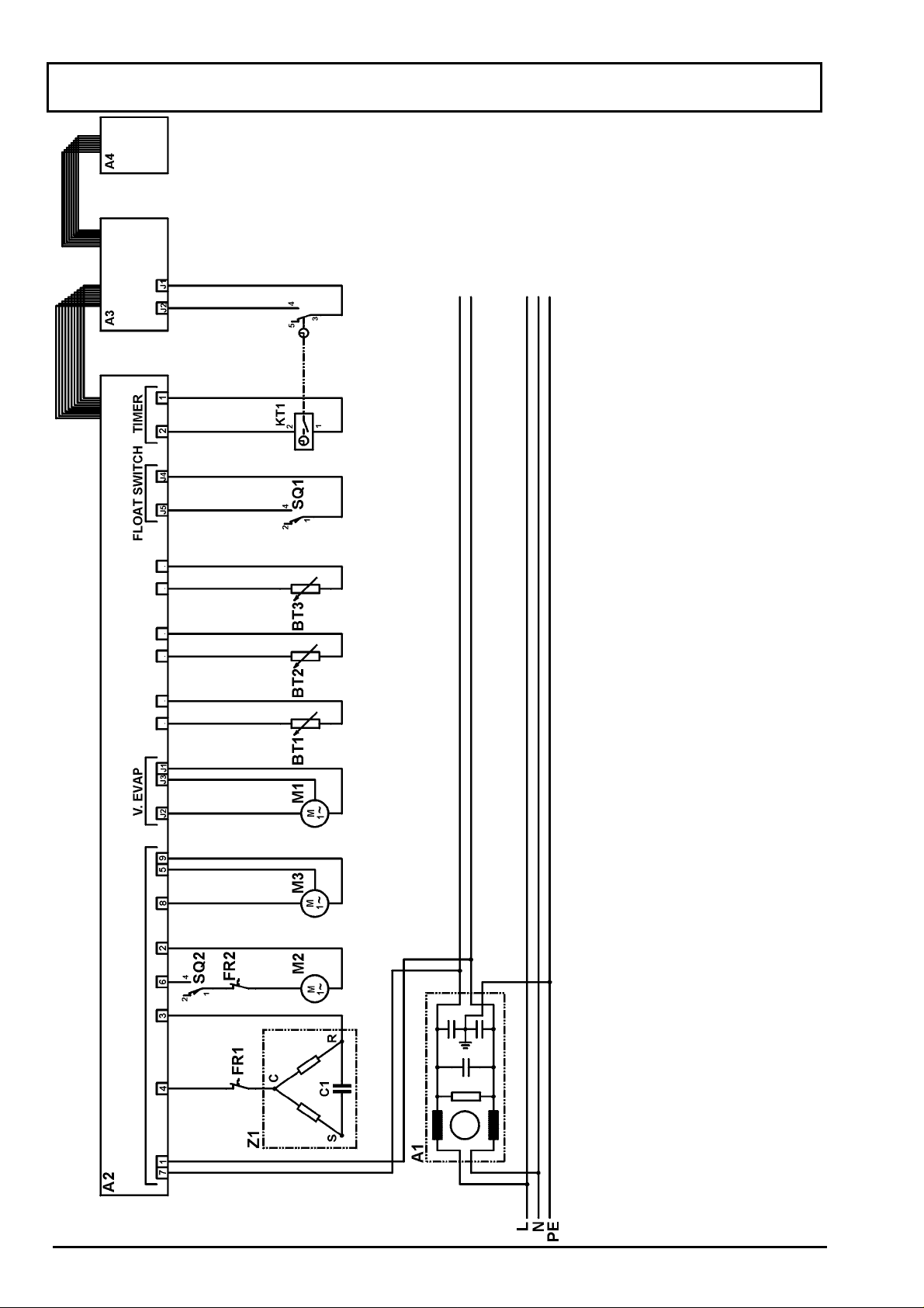
SCHEMA ELETTRICO / ELECTRICAL DIAGRAM / SCHALTPLAN
SCHEMA ELECTRIQUE / SCHEMA ELECT RICO
Legenda
Ficha electronica
Filtro
Ficha de potencia
Ficha de termostato
Ficha de las teclas
Sonda de temperatura
Sonda de mandata
Sonda evaporador
Condensador Z1
Protector Z1
Protector bomba
Programador
Ventilador evaporador
Bomba agua
Ventilador condensador
Resistencia
Microinterruptor max. nivel de agua
Microinterruptor bomba
Compressore
Legende
Fiche electronique
Filtre
Circuit imprimé
C.I. de thermostat
C.I. de touches
Sonde de temperature
Sonde de refoulement
Sonde évaporateur
Condensateur Z1
Zeichenerklärung
Platine
Funkentstörkondensator
Hauptplatine
Thermostatplatine
Tastenplatine
Raumtemperatursonde
Gas-Auslaßtemperatursonde
Verdampfer Sonde
Kondensator Z1
Legend
Electronic board
Anti-noise filter
Power board
Thermostat board
Switchboard
Room-temperature probe
Gas discharge probe
Evaporator probe
Z1 capacitor
Protecteur Z1
Protecteur pompe
Programmateur
Ventilateur évaporateur
Pompe de l'eau
Ventilateur condenseur
Elément chauffage
Microinterrupteur max. niveau eau
Microrupteur pompe
Compresseur
Kompressorschutz
Motorschutz Pumpe
Zeitschaltuhr
Verdamper-Ventilator
Wasserpumpe
Verflüssiger-Ventilator
Heizelement
Max. Wasserniveau-Mikroschalter
Mikroschalter Pumpe
Kompressor
Thermal protector Z1
Thermal protector pump
Timer
Evaporator ventilator
Water pump
Condenser ventilator
Heating element
Max water level microswitch
Pump microswitch
Compressore
Legenda
Scheda elettronica
Filtro antidisturbi
Scheda di potenza
Scheda termostato
Scheda tasti
Sonda temp. Ambiente
Sonda mandata
Sonda evaporatore
Condensatore Z1
Protettore termico Z1
Protettore Termico pompa
Timer
Ventilatore evaporatore
Pompa acqua
Ventilatore condensatore
Resistenza
Microinterruttore max. livello acqua
Micro pompa
A1A2A3A4BT1
BT2
BT3C1FR1
FR2
KT1M1M2M3R1
SQ1
SQ2
2 SCHEDA TECNICA 99031
Compressore
Z1
Page 3
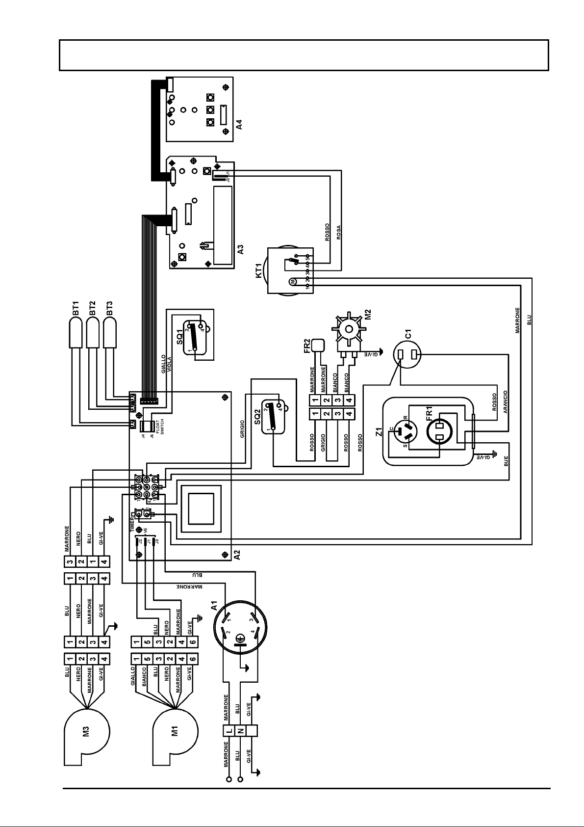
SCHEMA ELETTRICO / ELECTRICAL DIAGRAM / SCHALTPLAN
SCHEMA ELECTRIQUE / SCHEMA ELECT RICO
COLORES
Anaranjado
Blanco
Azul
Amarillo/Verde
Gris
Castano
Negro
Rosa
Rojo
Verde
Viola
COULEURES
Orange
Blanc
Bleu
Jaune/Vert
Gris
Marrone
Noir
Rose
Rouge
Vert
Violet
FARBEN
Orange
Weiß
Blau
Gelb/Grün
Grau
Braun
Schwarz
Rosa
Rot
Grün
Violett
COLOURS
Orange
White
Blue
Yellow/Green
Gray
Brown
Black
Pink
Red
Green
Violet
COLORI
Arancio
Bianco
Blu
GI-VE
Grigio
Marrone
Nero
Rosa
Rosso
Verde
Viola
3 SCHEDA TECNICA 99031
Page 4

VALORI DELLA SONDA NTC / RESISTANCE OF NTC PROBES
WIDERSTAND DER NTC-SONDEN / VALEURS DE LA SONDE NTC
VALORES DE LA SONDA NTC
Temperatura Resistenza Temperature Resistance Temperatur Widerstand
Température Résistance Temperatura Resistencia
°C
-5 42965 12 18113 29 8416
-4 40714 13 17271 30 8066
-3 38595 14 16473 31 7733
-2 36602 15 15718 32 7416
-1 34725 16 15002 33 7114
0 32956 17 14323 34 6826
1 31290 18 13679 35 6552
2 29715 19 13068 36 6290
3 28239 20 12489 37 6040
4 26840 21 11939 38 5802
5 25521 22 11416 39 5574
6 24276 23 10920 40 5357
7 23099 24 10448 41 5150
8 21988 25 10000 42 4952
9 20937 26 9574 43 4762
10 19943 27 9168
11 19003 28 8783
KΩΩΩΩ °C KΩΩΩΩ °C KΩΩΩΩ
PANELLO COMANDI
Spia ritar do 3 minuti
Spia timer ON
Tasto timer ON/OFF
Temperatura OK (lampeggia)
Tasto ON / OFF
Spia Alimentazi one /
allarm e (lampeggia)
Spia funzione “sleep”
Spia funzione “Auto”
Spia condizi onamento
Spia velocità massima
Spia velocità minima
Tasto condizionamento
Tasto velocità/funzione auto
Tasto “Sleep”
FUNZIONE DELLE SONDE ELET TRONICHE
L'apparecchio è equipaggiat o con tre sonde del tipo NTC (diminuendo l a temperat ura del cor po sonda aument a
la propria resistenza) che nell o schema elettrico sono identificat e con, BT1 (ambiente), BT 2 (mandata), BT3
(evaporatore).
E' possibile v erificare le sonde con un tester elet tronico di buona precisi one.
Sonda Ambiente BT1: legge la temperatura ambiente e manda un segnale alla basetta di controllo.
Quest'ultima confronta tale segnale con l'impostazione del tem ostato. A seconda del risultato decide se avviar e
l'apparecchio (temperatura sonda > temperatura impostata) oppure f ar lampeggiare la spia L9 (temperatura
sonda < temperatura im postata).
4 SCHEDA TECNICA 99031
Page 5

Sonda Mandata BT2: legge la temperatura del gas in usci ta dal compressore e manda un segnal e al la basetta
di controllo. Quest'ultima, a seconda della lettura, fa aumentare o diminuire la velocità del ventilatore
condensatore compensando la variazi one dei c ari chi ambiente. I valori di temper atura che permettono il c am bio
di velocità sono descri tti nella figura sott ostante.
Velocità massim a del
Ventilator e c ondensat or e
Velocità minima
Ventilator e c ondensat or e 80°C 92°C
Sonda evaporatore BT3: ha la funzione di prevenire la formazione di ghiaccio sull'evaporatore. Legge la
temperatura di evapor azi one del gas e se questa v a al di sotto di -4 gradi centi gradi passa autom at ic amente in
modalità anti ghiaccio. Quando questa f unzione è attiv a il condizionatore si fermerà per 5 m inuti ogni 20 mi nuti
di funzionamento. Il ventilatore esterno e il compressore saranno inattivi, mentre il ventilatore evaporatore
funzionerà al minimo dei giri.
Nei cinque minuti di sosta, il ghiaccio eventualmente form atosi sul le alette dell'ev aporatore, verrà sciolt o. La
macchina ripar te come di norma, rispettando i tre mi nuti di sicurezza del compressore.
FUNZIONI DELL'APPARECCH IO
La funzione "TIMER" (tasto T5 - spia L8)
Questa funzione permette di inserire o disinserire il tim er tramite il pulsante T 5. Quando il timer sarà inseri to la
spia L8 (Timer-on) rimarrà accesa.
ATTENZIONE: al rientro, da una mancanza di tensione, se la funzione " TIMER " era abilitata, la spia L8
lampeggia per avvertire l'utente di controllar e l'ora impostata sul timer. Questa funzione rim ane attiva fino ad
una pressione del t asto T5 senza disabilitare la f unzione.
La funzione " SLEEP " (tasto T4 - spia L7)
In questa modalità la gestione di tutte le funzioni è completamente automatica. Difatti il modo "SLEEP"
gestisce tutte tre le sonde; BT2 -sonda che rileva l a temperatura del gas di mandata del compressore, BT1 sonda che rileva la temperatura ambiente, BT3 - sonda che rileva la temperatura di evaporazione
all'evapor atore. Il termostato è disabilitato completamente.
Questa funzione permette di utilizzare il condizionat ore durante le ore notturne ric avandone un funzionamento
che sarà il giusto compromesso tra prestazi oni e silenziosit à. Per ott enere il migli or risult ato da questa f unzione
è consigli abile aver precedentemente c ondizionato l'ambiente.
Dopo l'inserimento della funzione tramite il tasto “SLEEP”, il condizionat ore funzionerà come segue:
- l' apparecc hio rim arrà acceso in c ondizi onament o per circa 20 minuti. (la velocit à del ventil ator e evaporat ore è
al minimo)
- trascorsi i 20 minuti il ventilatore evaporatore si spegne
- la t emper atura di evaporazi one comi ncia a scendere. A rriv ata a -10°C la sonda BT3 ferm a il c ompressore e il
ventilatore esterno mentre contemporaneamente la sonda BT1 registra la temperatura ambiente in quel
momento.
Il ciclo " SLEEP " verrà ripetuto solamente se la temperatura della stanza supererà di 3°C la temperatura
registrata al m omento dello spegni m ento del compressore, del la sonda BT 1, altrim enti il condi zi onatore rester à
inattivo.
La funzione "AUTO "
Se attiva la funzi one "AUTO", il condizionatore, trami te la sonda BT2, regola automaticament e la velocità del
ventilator e evaporat ore e del ventilat ore condensatore. La sogl ia di intervento è la stessa del f unzionamento
automatic o del ventilatore condensatore per cui , in "AUTO", i due ventilatori funzionano cont emporaneamente
alle stesse velocità .
La funzione " ANTIGHIACCIO " (automatica)
Previene la formaz ione di ghiaccio all'ev apor atore. E' un dispositivo c he entra in funzione automaticamente non
appena le temperature ( ambiente ed esterna) scendono sotto certi v alori. Quando è attiva il condizi onatore si
fermerà per 5 minuti ogni 20 minuti di funzionamento. Il ventilat ore esterno e il c ompressore saranno inatt ivi,
mentre il ventilatore evaporatore funzionerà al minimo dei giri.
Nei cinque minuti di sosta, il ghiaccio eventualmente formatosi sulle alette dell'evaporatore, verrà sciolto nel
giro di poco tem po.
La macchina ripar te come di norma, rispettando i tre mi nuti di sicurezza del compressore.
5 SCHEDA TECNICA 99031
Page 6

DIAGNOSTICA
)
a) Mancanza di tension e
Al rientro dopo una mancanza di tensione, la scheda riprende a funzionare nella modalità in cui si trovava
all'istante della mancanza di tensione stessa. Le eventuali tem pori z z azi oni in corso vengono resettat e.
b) Guasto ingressi an alo gi ci
Un guasto agli ingressi analogici (sonda aperta, sonda in corto, ecc.) viene segnalata sul frontale con il
lampeggio della spia L1 e provoca l'immedi ato disinserimento di tutte le f unzioni.
c) Allarme "MAX ACQUA "
Quando il livell o del l'acqua nella bacinella inter na del condizionatore si alza più del norm ale (esempio: se l a
pompa acqua non interviene), il galleggiante premerà il microinterruttore SQ1 che aprendo i contatti 1-2
provocherà l'immediato disinserimento del compressore e del ventilatore esterno, mentre quello interno
funzionerà alla minima velocità. La spia L1 lampeggiando segnalerà che l'apparecchio è in allarme.
AUTODIAGNOSI
La scheda di controllo del PAC40 ha la possibilità di effettuare automaticamente una verifica di alcuni
componenti .
Per eseguire il c ontrollo procedere come segue:
- togliere alimentazione all'apparec c hio
- accendere l' appar ec c hio tenendo premuti i tasti T1 e T5 per almeno 5 secondi
- appena tutte le lampade spia inizieranno a lampeggiare, rilasciare i tasti (le lampade spia dopo qualche
secondo si spegneranno). A questo punto inizia l' autodiagnosi:
- diagnosi ingressi analogici
se la sonda ambient e BT1 è in errore lam peggia il led L3 (veloci tà min)
se la sonda evaporatore BT3 è in errore lampeggia il led L4 (velocità max)
se la sonda di mandata BT 2 è in errore lam peggia il led L5 (AUTO)
se il termostato am biente è in errore lampeggia il led L9 ( "O K " temper atura)
- diagnosi ingressi digitali
se il timer elettronico è aperto la spia L8 si accende; altr imenti rimane spenta
se il microinterruttore SQ1 è chiuso (contatti 1-2 aperti / 1-4 chiusi) la spia L1 si accende; altrimenti
rimane spenta
Se dopo la fine del lampeggio iniziale nessuna spia rimane accesa significa che non ci sono guasti
nelle funzioni sopra descritte.
Si esce dalla modalità autodiagnosi nel seguente modo:
- togliere alimentazione all'appar ec c hio
- riacc enderlo e premere il tasto ON/OFF
L8 Timer aperto
T1 Tasto timer ON/OFF
L1 Allarme livello acqua
L5 Errore sonda mandata (BT2)
L9 Errore termostato (A3)
T1 Tasto ON / OFF
L4 Errore sonda evaporator e (BT 3)
L3 Errore sonda ambiente (BT1
6 SCHEDA TECNICA 99031
Page 7

VALORI DELLA SONDA NTC / RESISTANCE OF NTC PROBES
WIDERSTAND DER NTC-SONDEN / VALEURS DE LA SONDE NTC
VALORES DE LA SONDA NTC
Temperatura Resistenza Temperature Resistance Temperatur Widerstand
Température Résistance Temperatura Resistencia
°C
-5 42965 12 18113 29 8416
-4 40714 13 17271 30 8066
-3 38595 14 16473 31 7733
-2 36602 15 15718 32 7416
-1 34725 16 15002 33 7114
0 32956 17 14323 34 6826
1 31290 18 13679 35 6552
2 29715 19 13068 36 6290
3 28239 20 12489 37 6040
4 26840 21 11939 38 5802
5 25521 22 11416 39 5574
6 24276 23 10920 40 5357
7 23099 24 10448 41 5150
8 21988 25 10000 42 4952
9 20937 26 9574 43 4762
10 19943 27 9168
11 19003 28 8783
KΩΩΩΩ °C KΩΩΩΩ °C KΩΩΩΩ
CONTROL PANEL
3 minute time delay
Timer ON control lamp
Timer ON
Room temp. OK (flashing)
ON / OFF k e y
Power / alarm (flashing)
Control lamp “sleep”
Control lamp “ auto”
Control lamp “conditioning”
Control lamp “max speed”
Control lamp “min. speed”
”Conditioning” Key
Speed/Auto function selector
“Sleep” Key
ELECTRONIC SENSOR FUNCTIONS
The unit is equipped with t hree NTC type sensors (sensor resistanc e increase s directl y as the t emperature of
the sensor body incr eases), ident ifi ed in the wiri ng diagram as BT1 (ambient temp.), BT 2 (gas di scharge temp)
and BT3 (evaporator temp).
The sensors can be checked using a hi gh-precisi on electronic tester. See the relativ e chart reporti ng values at
the various tem per atures.
Room temperatu re sensor BT 1: reads room temperatur e and sends a signal to the control base. The base
compares this signal with the thermostat setting. Dependi ng on the results, it decides whether to star t up the
unit (sensor temperature > set temperat ur e) , or to star t Temperature OK light flashing ( sen sor t emperature < set
temperature) .
7 SCHEDA TECNICA 99031
Page 8

Gas discharge senso r BT2: reads gas temperature at compressor outlet and sends a signal to the control
base. Depending on the reading, the base increases or decreases the speed of the condenser fan,
compensating for variations in ambient load. The temperature levels which enable the speed change are
reported in the figure below.
Condenser ventilator
High speed
Condenser ventilator
Low speed 80°C 92° C
Evaporator temperature sensor BT3: its function is to prevent the form ation of ice on t he evaporat or. The gas
evaporation temper ature is measured; if it drops below -4 °C, the device automati cally enables the antifreez e
mode. When this functi on is activated, the conditi oner stops for 5 minutes every 20 mi nutes of operation. The
external f an and compr essor are di s-activated, while the evaporator fan runs at minimum speed.
During the 5-minute rest period, any ice whic h has formed on the evaporator fins melt s in short time. The unit
starts up again normally, respecting the 3-minute compressor safet y period.
UNIT FUNCTIONS
"TIMER" functi on (key T5 - indicat or light L8)
This function enables/disables the timer, using pushbutton T5. When t he tim er is on, indicator light L8 (timer on)
stays on.
ATTENTION : after a power fail ure (if the “T IMER” functi on had previ ously been enabl ed) , i ndicat or li ght L8 will
begin to flash to warn the user t o check the time set on the timer. This functi on remains act ive until k ey T5 is
pressed, without disabling the functi on.
“SLEEP” function ( key T4 - indicat or light L7)
In this mode, control of all functions is completely automatic. In fact, the “SLEEP” mode controls all three
sensors; BT2 - the sensor that measures gas tem perature at compressor outlet, BT1 - the sensor that checks
room temperat ure, and BT3 - the sensor that measures the evaporation temperature at the evaporator. The
thermostat is completely disabled.
This function allows you to use the conditioner at ni ght, guaranteeing t he best combination of perf ormance and
silent running. For best results using thi s f unc tion, the room should already be condi tioned.
When pushbutton T4 i s depressed, the conditioner will function as follows:
- the uni t will remain on, in the condi tioni ng mode, f or approx. 20 minutes (the speed of the evapor ator fan is at
a minimum).
- after 20 minutes, the evaporator f an switc hes off.
- the evaporation temperature begins to drop. When it has fallen to -10 °C, the BT3 sensor stops the
compressor and external f an, while the BT1 sensor sim ultaneously measures the room temperat ure at that
moment.
The “SLEEP” cycl e is repeated only if the room t emperature i s 3 ° C higher than the temperature m easured by
the BT1 sensor at the time at which the compressor switched off , ot her wise the c onditioner remains off.
“AUTO” function (Key T3 - indicator light L5)
If the “AUTO” function is activated, t he conditioner aut omatically regul ates the speed of the evaporat or fan and
the condenser fan, thr ough the SM sensor. The enabling threshol d is the same as for automatic operation of the
condenser fan, so that on “AUTO” the two fans run simult aneousl y at t he same speed.
The “ANTIFREEZE” function (automatic)
Prevents formation of ice in the evaporat or. The device is enabled automatically as soon as the tem perature
(room and outdoor) dr ops below a giv en l evel. W hen it is activ ated, the conditi oner stops runni ng f or 5 m inut es
every 20 minutes of operation. The external fan and c om pressor are not active, while the evaporator fan r uns at
the lowest speed.
During the 5-mi nute rest period, any ice formed on the ev apor ator fins will melt within a short tim e.
The machine will star t up again normally, respecting the 3-minute compressor saf ety period.
8 SCHEDA TECNICA 99031
Page 9

DIAGNOSTICS
)
a) Power failure
After a power failure, the circuit board will resum e running i n the mode it was set to at the moment of the power
cut-off. Timers will be reset.
b) Analog input failure
An analog input failure (sensor open, sensor short circuit, etc.) will be signalled on the front panel by the
flashing of indicator li ght L1, provoking the immediat e di sabli ng of all functions.
c) “MAX WATER” alarm
When the water lev el in the pan inside the conditioner i s higher than normal (f or example, if the water pump is
not working), t he float will activ ate the SQ1 microswitch which closes contac ts 1-4, provoking the immediate
disabling of the compressor and external fan, while the internal fan continues to run at the lowest speed.
Indicator light L1 will begin flashing to signal the alarm condition.
SELF-DIAGNOSIS
The PAC 40 control card c an be set to run an automatic check on several components.
Proceed as follows :
- switch off and unplug the conditioner
- press keys T1 and T5 while you replug the conditioner and keep them pressed f or at least f ive seconds
- as soon as all the indication lights start flashing, r elease the keys (the indicator light s will go out after a few
seconds). At t his poi nt, the self-diagnosis process begi ns :
- analog input diagnosis
- if there is an error in the BT1 room tem perature sensor, led L3 start s flashing (min. speed)
- if there is an error in the BT3 evapor ator sensor, led L4 starts flashi ng (max. speed)
- if there is an error in the BT2 gas discharge sen sor, led L5 starts flashing (A UTO )
- if there is an error in the room tem per ature thermostat, led L9 star ts flashing (temperature “OK”)
- digital input diagnosi s
- if the electronic timer open, indicator li ght L8 lights up (otherwise it remains off)
- if microswitch SQ1 is cl osed (contacts 1-2 open / 1-4 cl osed), indicat or light L1 light s up ( otherwise i t
remains off).
If none of the indicator light s remains on, after the initial flashing stops, this mean s that there is no
fault in any of the functions described above.
To exit from the self- diagnosis mode :
- switch off power supply
- switch the unit back on and press k ey T1.
L8 Timer open
T1 Key timer ON/OFF
L1 High water level alarm
L5 Error discharge probe (BT2)
L4 Error evaporator probe (BT3)
L3 Error room sensor (BT1
L9 Thermostat error (A3)
T1 Key ON / OFF
9 SCHEDA TECNICA 99031
 Loading...