

Page 1

CONDIZIONATORI / AIR CONDITIONERS / KLIMAGERÄTE
CLIMATISEURS D'AIR / ACONDICIONADORES DE AIRE
DE’LONGHI PAC 50
(INT)
DATI TECNICI / TECHNICAL DATA / TECHNISCHE DATE N
DONNEES TECHNIQUES / DATOS TECNICOS
Tensione / Voltage / Spannung / Tension / Tension V / Hz 220 … 240 / 50
Max. potenza assorbita / Max. input power / Max.Leistungsaufnahme W 960
Max. puissance absorbée / Max. potencia absorbida
Potenza di raffreddamento / Cooling capacity / Kühlleistung W 2500 (*)
Puissance de climatisation / Potencia de acondicionamiento
Compressore / C ompresso r / Kompress o r / Compresseu r / Compress o r Type SANYO 806.673.45 TEC U MSEH (**)
RGA5485EXC
- avvolgimento / winding / Wicklung / bobinage / envolvimiento (Start/Run) Ω 6.8 / 4.6 10.72 / 4.3
- protettore termico / thermal prot ector / t hermische S icherung Typ e MRA 98635-6 T89032-77
protecteur thermique / protector térmico (Off-On)°C 145 – 69 ----------------
- condensatore / capacitor / Kondensator / condensateur / condensador µF20 15
Ventilatore condensatore / Condenser ventilator / Verflüssiger-Ventilator Type E.B.M. G2E140 NO4 7- 2 1
Ventilateur condenseur / Ventilador condensador
- avvolgimento / winding / Wicklung / bobinage / envolvimiento (Start/Run) Ω 144 - 106
- potenza assorbita / input power / Leistungsaufnahme W 108
puissance absorbé / potencia assorbida
- condensatore / capacitor / Kondensator / condensateur / condensador µF2
Ventilatore evaporatore / Evaporator ventilator / Verdampfer-Ventilator Type EMC RF4C – 133/190
Ventilateur évaporateur / Ventilador evaporador
- avvolgimento / winding / Wicklung / bobinage / envolvimiento (Start/Run) Ω 455 / 966
- potenza assorbita / input power / Leistungsaufnahme W 25
puissance absorbé / potencia assorbida
- condensatore / capacitor / Kondensator / condensateur / condensador µF1.25
Termost a to / Thermostat / Thermostat / Therm o st at / Termostato Type IMIT TR2
- attacco-stacco / on-off / ein-aus / marche-arrêt / cerrado-abierto °C 1.5 (±5) – 39 (±3) ∆T 2
Sonda antighiaccio / No frost probe / Frostschutzsonde / Sonde antigrivre / Sonda antihielo Type NTC NTH2014B
- resistenza / resistance / Widerstand / résistance / resistencia KΩ 2 A 25°c
- apre - chiude / open - close / auf - zu / ouvert - fermé / abierto – cerrado °C -5 / +2
Pressostato / Pressosta t / Druckschalter / Pressostat / Pressos tato (***) Kg/cm228 ( manual reset )
Commutatore / Commutator / Funktionswahlschalter/ Selecteur / Commutador V / A 250 / 16
Pompa acqua / Water pump / Wasserpumpe / Pompe de l'eau / Bomba agua Type ASKOLL 290946
- avvolgimento / winding / Wicklung / bobinage / envolvimiento Ω 185
- potenza assorbita / input power / Leistungsaufnahme W 30
puissance absorbée / potencia absorbida
Timer / Timer / Zeitschaltuhr / Programmateur / Programador Type GRÄSSLIN FM/1 StuZH, 24
Dati di press ione / Pres sures data / D ruck Da ten / Caract éristiques de pression / D atos de presión W ater Air
Alta pressione / Hi gh pr essure side / Hoher Dr uc k / Haut e pression / Alta presión bar 16.4 21.7
Bassa pressione / Low pressure side / Niedriger Druck / Basse pression / Baja presión bar 4.86 5.08
Carica freon / Freon c har ge / Freon Menge / Quantité du Fréon / Carga de freon (R22)gr 540
SANYO
(R22) gr 470 TECUMSEH
(***) SOLO/ONLY/NUR/SEULEMENT/SOLO PAC 50
(**) SOLO/ONLY/NUR/SEULEMENT/SOLO PAC50/2000
(*) ATTENTION:
Tutti i dati dichiarati sono relativi a: / All data are referred to: / Alle Daten beziehen sich auf:/Toutes les données regardents à: / Todos los datos se refieren a:
Temperatura ambiente Room temperature Raumtemperatur Température dans la piéce Temperatura ambiente 27 °C
Temperatura esterna Outdoor temperature Außentemperatur Température externe Temperature externa 35 °C
Umidità relativa Relative humidity Relative Feuchtigkeit Humidité relative Humidad relativa 50 %
SCHEDA TECNICA ST0776/99025/1
Page 2
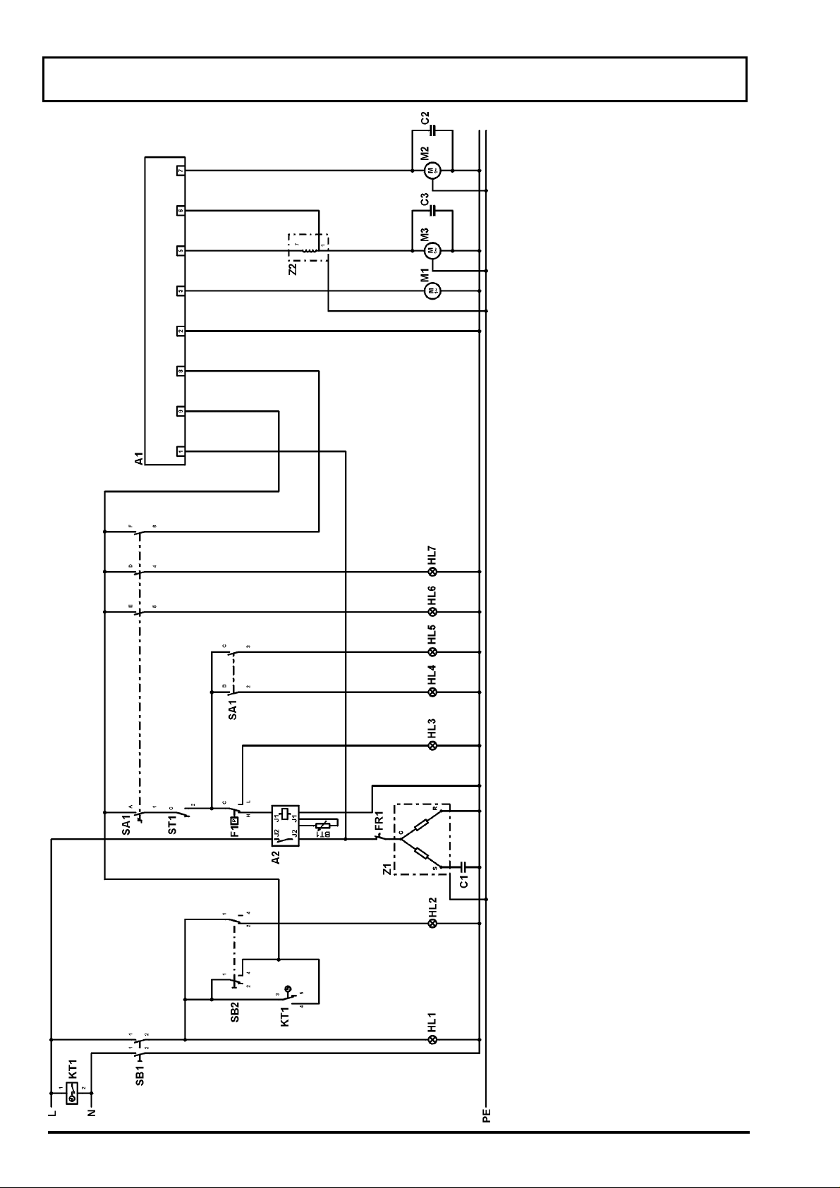
SCHEMA ELETTRICO / ELECTRICAL DIAGRAM / SCHALTPLAN
SCHEMA ELECTRIQUE / SCHEMA ELECTRICO PAC 50 / 1999
Legenda
Ficha electronica
Retardador 3 minutos
Sonda antihielo
Condensador Z1
Condensador M2
Condensador M3
Pressostato
Protector Z1
Piloto encendido/apagado
Piloto "timer on"
Piloto de alarma
Piloto min. acondic.
Piloto max. acondic.
Piloto max. ventilación
Piloto min. ventilación
Programador
Bomba agua
Ventilador evaporador
Ventilador condensador
Commutador
Interruptor generale
Interr. Programador
Termostato ambiente
Compressore
Impedancia M3
Legende
Fiche electronique
Ritardateur 3 minutes
Sonde antigrivre
Condensateur Z1
Condensateur M2
Condensateur M3
Pressostat
Protecteur Z1
Voyant marche/arrêt
Voyant "timer on"
Zeichenerklärung
Schwimmerschalter-Platine
3 Min.Zeitverzögerer
Frostschutzsonde
Kondensator Z1
Kondensator M2
Kondensator M3
Druckschalter
Kompressorschutz
Ein-Aus-Kontrolleuchte
"Timer AN" Kontrolleuchte
Legend
Flaot switch board
Three minutes time delay
No-frost-probe
Z1 capacitor
M2 capacitor
M3 capacitor
Pressostat
Thermal protector Z1
ON/OFF warnig light
"Timer ON" warning light
Voyant dé alerte
Voyant min. climat.
Voyant max. climat.
Voyant max. ventilation
Voyant min. ventilation
Programmateur
Pompe de l'eau
Ventilateur évaporateur
Ventilateur condenseur
Selecteur
Interrupteur générale
Tinterr. Programmateur
Ambiance termostat
Allarmleuchte Systemdruck
Leuchte min. Kühlung
Leuchte max. Kühlung
Leuchte max. Ventilation
Leuchte min. Ventilation
Zeitschaltuhr
Wasserpumpe
Verdamper-Ventilator
Verflüssiger-Ventilator
Funktionswahlschalter
Hauptschalter
Zeitschaltuhr Umschalter
Raumthermostat
High pressure allarm light
Light min. conditioning
Light max. conditioning
Light max. ventilation
Light min. ventilation
Timer
Water pump
Evaporator ventilator
Condenser ventilator
Funtion changeover switch
Main switch
Timer ON/OFF switch
Ambient thermostat
Compresseur
Impédance M3
Kompressor
Vorwiderstand M3
Compressore
M3 impedance
Legenda
Scheda galleggiante
Ritardatore 3 minuti
Sonda antighiaccio
Condensatore Z1
Condensatore M2
Condensatore M3
Presostato
Protettore Termico Z1
Spia acceso/spento
Spia timer inserito
Spia allarme pressione
Spia max. condizionamento
Spia min. condizionamento
Spia max. ventilazione
Spia min. ventilazione
Timer
Pompa acqua
Ventilatore evaporatore
Ventilatore condensatore
Commutatore funzioni
Interruttore generale
Comm. Timer acc/spento
Termostato ambiente
Compressore
A1A2BT1C1C2C3F1
FR1
HL1
HL2
HL3
HL4
HL5
HL6
HL7
KT1M1M2M3SA1
SB1
SB2
ST1Z1Z2
2 SCHEDA TECNICA ST0776/99025/1
Impedenza M3
Page 3

SCHEMA ELETTRICO / ELECTRICAL DIAGRAM / SCHALTPLAN
SCHEMA ELECTRIQUE / SCHEMA ELECTRICO PAC 50 / 1999
POSITION Z2
Pos.1
Pos. 1
Pos. 7
EBM / OLMO
MOTOR TYPE
Pink
Black
White
Wire colours
COLORES
Anaranjado
Blanco
Azul
Amarillo/Verde
Gris
Castano
Negro
Rosa
Rojo
Verde
Viola
COULEURES
Orange
Blanc
Bleu
Jaune/Vert
Gris
Marrone
Noir
Rose
Rouge
Vert
Violet
FARBEN
Orange
Weiß
Blau
Gelb/Grün
Grau
Braun
Schwarz
Rosa
Rot
Grün
Violett
COLOURS
Orange
White
Blue
Yellow/Green
Gray
Brown
Black
Pink
Red
Green
Violet
COLORI
Arancio
Bianco
Blu
GI-VE
Grigio
Marrone
Nero
Rosa
Rosso
Verde
Viola
3 SCHEDA TECNICA ST0776/99025/1
Page 4

g
g
g
g
y
y
y
y
g
g
y
g
g
g
g
g
g
g
g
g
g
g
g
SCHEMA ELETTRICO / ELECTRICAL DIAGRAM / SCHALTPLAN
SCHEMA ELECTRIQUE / SCHEMA ELECTRICO PAC 50 /2000
ado
enda
Le
Ficha electronica
Sonda antihielo
Condensador Z1
Condensador M2
Condensador M3
Protector Z1
Piloto encendido/apa
Piloto "timer on"
Piloto de alarma
Piloto min. acondic.
Piloto max. acondic.
Piloto max. ventilación
Piloto min. ventilación
Piloto "turbo on"
Programador
Bomba agua
enerale
Ventilador evaporador
Ventilador condensador
Commutador
Interruptor
Interr. Programador
Interruptor turbo
Termostato ambiente
Compressore
Impedancia M3
énérale
ende
Le
Fiche electronique
Sonde antigrivre
Condensateur Z1
Zeichenerklärun
Schwimmerschalter-Platine
Frostschutzsonde
Kondensator Z1
end
Le
Flaot switch board
No-frost-probe
Z1 capacitor
ant marche/arrêt
ant dé alerte
Condensateur M2
Condensateur M3
Protecteur Z1
Vo
Voyant "timer on"
Vo
stemdruck
Kondensator M2
Kondensator M3
Kompressorschutz
Ein-Aus-Kontrolleuchte
"Timer AN" Kontrolleuchte
Allarmleuchte S
ht
ht
li
h pressure allarm li
M2 capacitor
M3 capacitor
Thermal protector Z1
ON/OFF warni
"Timer ON" warning light
Hi
ant min. ventilation
ant max. climat.
Voyant max. ventilation
Vo
Voyant "turbo on"
Programmateur
Pompe de l'eau
Ventilateur évaporateur
Voyant min. climat.
Vo
Leuchte min. Kühlung
Leuchte max. Kühlun
Leuchte max. Ventilation
Leuchte min. Ventilation
"Turbo AN" Kontrolleuchte
ht min. ventilation
ht max. conditionin
"Turbo ON" warning light
Light max. ventilation
Li
Light min. conditioning
Li
Ventilateur condenseur
er-Ventilator
Zeitschaltuhr
Wasserpumpe
Verdamper-Ventilator
Verflüssi
Timer
Water pump
Evaporator ventilator
Condenser ventilator
Selecteur
Interrupteur
Tinterr. Programmateur
Interrupteur turbo
Ambiance termostat
Compresseur
Impédance M3
Funktionswahlschalter
Hauptschalter
Zeitschaltuhr Umschalter
Turbo schalter
Raumthermostat
Kompressor
Vorwiderstand M3
Funtion changeover switch
Main switch
Timer ON/OFF switch
Turbo switch
Ambient thermostat
Compressore
M3 impedance
enerale
enda
Comm. Timer acc/spento
Interruttore turbo
Termostato ambiente
Compressore
SB3
ST1Z1Z2
Impedenza M3
Le
Scheda galleggiante
Sonda antighiaccio
Condensatore Z1
Condensatore M2
Condensatore M3
Protettore Termico Z1
Spia acceso/spento
Spia timer inserito
Spia allarme pressione
Spia max. condizionamento
Spia min. condizionamento
Spia max. ventilazione
Spia min. ventilazione
Spia turbo inserito
Timer
Pompa acqua
Ventilatore evaporatore
Ventilatore condensatore
Commutatore funzioni
Interruttore
A1
BT1C1C2C3FR1
4 SCHEDA TECNICA ST0776/99025/1
HL1
HL2
HL3
HL4
HL5
HL6
HL7
HL8
KT1M1M2M3SA1
SB1
SB2
Page 5

SCHEMA ELETTRICO / ELECTRICAL DIAGRAM / SCHALTPLAN
SCHEMA ELECTRIQUE / SCHEMA ELECTRICO PAC 50 /2000
Arancio
Bianco
Blu
GI-VE
Grigio
Marrone
Nero
Rosa
Rosso
Verde
Viola
COLORI
Anaranjado
Blanco
Azul
Amarillo/Verde
Gris
Castano
Negro
Rosa
Rojo
Verde
Viola
COLORES
Orange
Blanc
Bleu
Jaune/Vert
Gris
Marrone
Noir
Rose
Rouge
Vert
Violet
COULEURES
Orange
Weiß
Blau
Gelb/Grün
Grau
Braun
Schwarz
Rosa
Rot
Grün
Violett
FARBEN
Orange
White
Blue
Yellow/Green
Gray
Brown
Black
Pink
Red
Green
Violet
COLOURS
5 SCHEDA TECNICA ST0776/99025/1
Page 6

ACCESSIBILITÀ / ACCESSIBILITY / ZUGÄNGLICHKEIT
1. Per accedere alle parti interne del condizionatore, rimuo vere il filtro dell‘aria,
togliere la tanica e svuotare la bacinella interna attraverso il tubo di scarico
(fig.1). Svitare la vite nelle maniglie e le due viti nella parte bassa dei fianchi.
(fig.2)
In order to have access to the air-conditioner, remove the air filter, water tank
and drain the water tray in the inside of the air-conditioner through the draining
hose in the back of the appliance
from either side panel as shown in fig. 2.
Um Zugang zu den Geräteteilen zu gewinnen,
entfernen Sie den Luftfilter, Wassertank und
entleeren Sie die Wasserschale durch den
Ablaßschlauch (Fig.1). Entfernen Sie nun
beidseitig die Schraube im Griff und die beiden
Schr auben der Seitenunterkanten (fig.2).
2. Svitare le quattro viti che fissano il
frontale più le sei viti che fissano il retro
dell’apparecchio. (fig.3 e 4)
Unscrew the f o ur screws which hold the
front and the six screws which hold the
back of the appliance (fig.3 and 4).
Entfernen Sie nun die vier Schrauben
der Vorderfront und die sechs
Schrauben der Rückwand und
entfernen Sie beide Gehäuseteile. (fig.
3 und 4)
(fig .1 )
. Unscrew the three indicated screws
fig. 1
fig. 3
fig. 2
fig. 4
3. Per cambiare componenti elettrici
posizionati sul lato destra, svitare le quattro viti
indicati (fig.5) ed estrarre supporto componenti.
In order to change any electric component
situated on the right side of the air-conditioner,
unscrew the four indicated screws (fig. 5) and
extract the complete support for the components.
Um die in der rechten, unteren Geräteseite
befindlichen elektrischen Bauteile zu wechseln,
entfernen Sie die in fig. 5 gekennzeichneten vier
Schrauben und ziehen Sie die Befestigungsplatte
wie in fig. 6 gez eigt heraus.
4. Per togliere la pompa svitare la tre vite indicati in fig. 7.
Attenzione
rimontare la pompa è obbligatorio svuotare completamente la bacinella,
assicurarsi che la guarnizione sia montata bene e premere ben fermo la
pompa nella sua sede prima di avvitarla.
In order to change the water pump, unscrew the three indicated screws
in fig. 7. Attenti on: Before mounting the new pump, drain all water from
the tray, make sure that the gasket is perfectly in place and press the
pump firmly into it’s seat before screwing it into place
Um die Pumpe auszutauschen, entfernen Sie die drei in fig. 7
gekennzeichneten Schrauben und heben Sie die alte Pumpe heraus.
Achtung
: Bevor Sie die neue Pumpe einsetzen, entleeren Sie
vollständig alles Wasser aus dem Behälter und achten Sie darauf, daß
die Dichtung perfekt aufgesetzt ist. Drücken Sie die Pumpe vorsichtig in
ihren Platz bevor Si e Di es e fes tsc hrauben.
fig.5
fig.6
: Per
fig.7
6 SCHEDA TECNICA ST0776/99025/1
 Loading...