

Page 1

FORNI MICROONDE / MICROWAVE OVENS
MIKROWELLENGERÄTE / FOURS A MICRONDES
DATI TECNICI / TECHNICAL DATA / TECHNISCHE DATEN
DONNEESTECHNIQUES/DATOSTECNICOS
HORNO MICROONDAS
DE' LONGHI MW421
Voltaggio / Voltage / Spannung / Voltage / Voltaje
Max.potenza assorbita / Max. input power / Max.Leistungsaufnahme
Max.puissance absorbée / Max.potencia absorbida
Potenza microonde / Microwave output / Mikrowellenleistung
Puissance de sortie microondes / Potencia cedida microondas
Magnetron
- termostato sicurezza / safety thermostat / Sicherheitsthermostat
thermostat de sécurité / Termostato de seguridad
Resistenza grill / Grill heating element / Grill-Heizkörper
Elément chauffant gril / Resistencia grill
Termostato grill / Grill thermostat / Grill-Thermostat
Thermostat gril / Termostato del grill
Trasformatore / Transformer / Transformator / Transformateur / Transformador
- avvolgimento primario / primary winding / Wicklung primär
bobinage primaire / envolvimiento primario
- avvolgimento secondario / secondary winding / Wicklung sekundär
bobinage secondaire / envolvimiento secondario
- avvolgimento filamento / filament winding / Glühfaden-Wicklung
bobinage filament / envolvimiento filamento
Condensatore / Capacitor / Kondensator / Condensateur / Condensador
V/Hz
W
W
Type
Type
°C
W
°C
Type
V/W
V/W
mF
230-50
2250
750
Toshiba 2M240J-AN
Texas PK1
145
1000
75
DeoBo
DB-80DEA
230 - 2.3
2050 - 115
3.2
V
0.95
Diodo / Diode / Diode / Diode / Diodo
Ventilatore / Ventilator / Ventilator / Ventilateur / Ventilador
- avvolgimento / winding / Wicklung / bobinage / envolvimiento
Contaminuti / Timer / Zeitschaltuhr / Programmateur / Programador
- avvolgimento / winding / Wicklung / bobinage / envolvimiento
Microinterruttori / Microswitches / Mikroschalter
Microrupteurs / Microinterruptores
Diodo protezione/Protection diode/Schutzdiode
Diode de protection/Diodo de protecciòn
Motore piatto / Turntable motor / Drehteller-Motor
Moteur plateau tournant / Motor del plato giratorio
Lampada / Lamp / Lampe / lampe / Lámpara
Fusibile / Fuse / Schmelzsicherung / Fusible / Fusibile
Type
Type /W
W
Type
kW
Type
V/A
Type
Type
W
W
SankenHVR1XóFciHVR0309
Johnson SP - 6309-230 / 25
262.5
Nakagawa VFH35MVF04E
21
SodecoóSaiaó Xgaw óCrouzet
250/12
FCI HV 06X1P5
JAEST-16MN73SYAWF
3 / 2.5
25
8F type Fusit or Omega
A
1
SCHEDA TECNICA 97047
Page 2
NF+F
S1
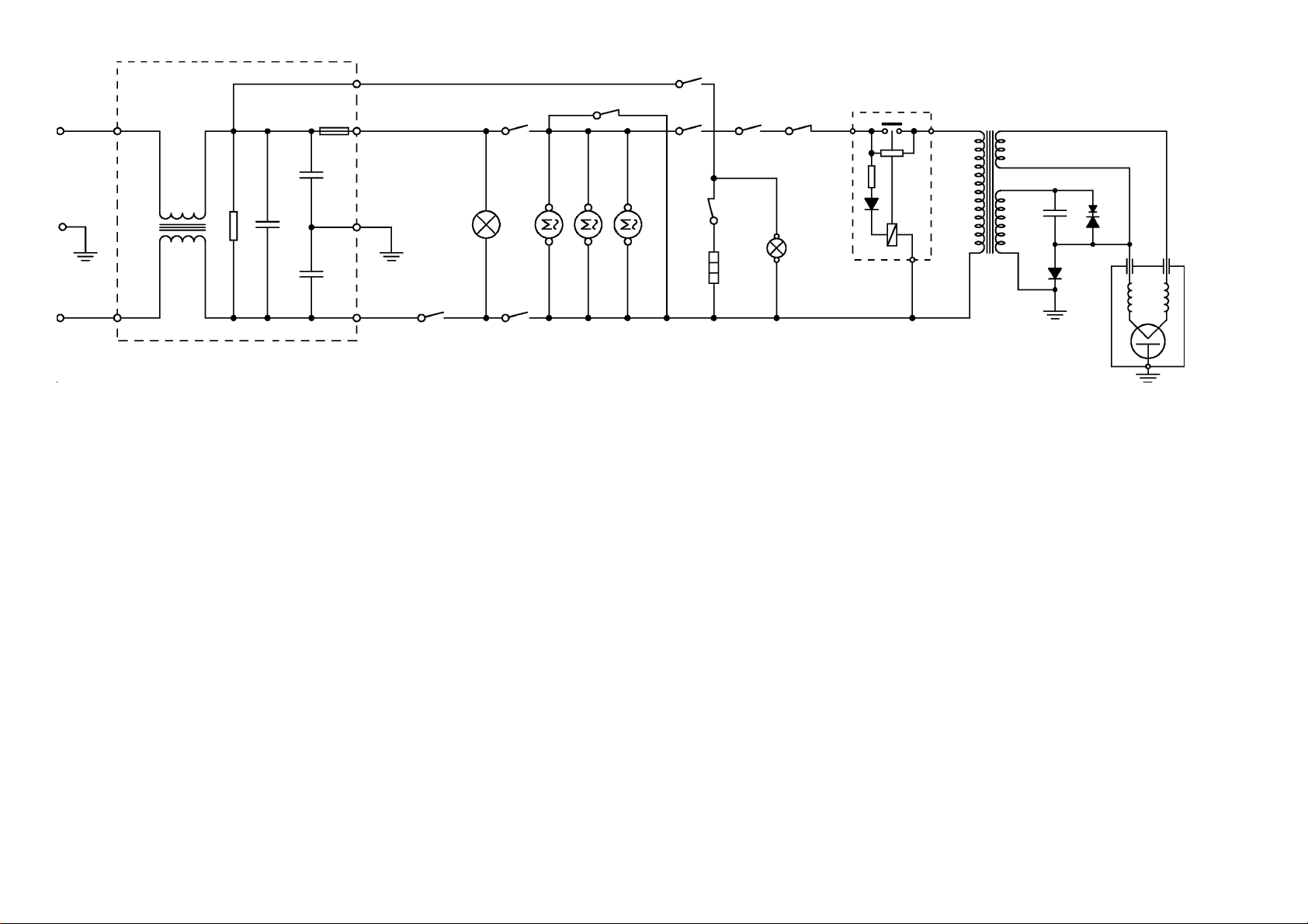
SCHEMA ELETTRICO / ELECTRIC DIAGRAM / SCHALTPLAN
SCHEMA ELECTRIQUE / ESQUEMA ELECTRICO
Porta aperta / Door open / Tür auf / Porte ouverte / Puerta abierta
2
SCHEDA TECNICA 97047
LEGENDA -LEGEND-ZEICHENERKLÄRUNG-LEGENDE-LEGENDA
DM Motore piatto rotante Turntable motor Drehteller-Motor Moteur plateau tournant Motor del plato giratorio
F Fusibile8AEM Fuse 8A EM Schmelzsicherung 8A EM Fusible 8A Fusible8AEM
FM Ventilatore magnetron Magnetron ventilator Magnetron-Ventilator Ventilateur magnetron Ventilador magnetron
HVC Condensatore alta tensione High voltage capacitor Hochspannungskondensator Condensateur h.t. Condensador a.t.
HVD Diodo rettificatore a.t. High voltage retifier diode Hochspannungsdiode Diode h.t. Diodo a.t.
HVT Trasformatore alta tensione High voltage transformer Hochspannungstransformator Transformateur h.t. Transformador a.t.
LSG Lampadaspiagrill Grill warning light Grill-Kontrollampe Voyant du grille Pilotogrill
MGT Magnetron Magnetron Magnetron Magnetron Magnetron
MON Microinterruttore monitor Monitor microswitch Monitor Mikroschalter Microrupteur monitor Microinterruptor monitor
NF+F Filtroantidisturbo +Fusibile Anti-noise filter + Fuse Funkentstörfilter + Sicherung Fltre+ Fusible Filtro+Fusible
OL Lampada forno Oven light Ofenbeleuchtung Lampe du four Lámpada horno
PRI Micronterruttore primario Primary microswitch Mikroschalter primär Microrupteur primaire Microinterruptor primario
PDX Diodo di protezione Protectiondiode Schutz diode DiodeProtection DiodeProtecciòn
RG Resistenza grill Grillheatingelement Grill-Heizkörper Elément chauffant gril Resistencia grill
S. LIM Scheda limitatore di picco Peaklimiterboard StrombegrenzerPlatine Limiteur de courant Limitador de corriente
S1-S2 Contatticommutatore Change over switch contacts Kontakte des Umschalters Contacts du commutateur Contactos del conmutador
SEC Microinterruttore secondario Secondary microswitch Mikroschalter sekundär Microrupteur secondaire Microinterruptor secundario
SW1 Contattotimer Timer contact Kontakt der Zeitschaltuhr Contact du timer Contactos timer
SW2 Contatto regolatore potenza Power level regulating contact Leistungsmikroschalter Microrupteur regulateur de puissance Microinterruptor regulador potencia
THG Termostatogrill Grill thermostat Grill-Thermostat Thermostatgril Termostatogrilll
TIMER Timer Timer Zeitschaltuhr Programmateur Programador
TM Motore timer Timermotor Zeitschaltuhr-Motor Moteur programmateur Motor programador
TH.MGT Protettore magnetron Magnetron protector Magnetron Temperaturbegrenzer Protecteur magnetron Protector magnetron
F
SW1
PRI
OL
SEC
MON
TMFM
THG
DM
RG
TH.MGT
SW2S2
LSG
S.LIM
HVT
HVC
PDX
HVD
MGT
Page 3
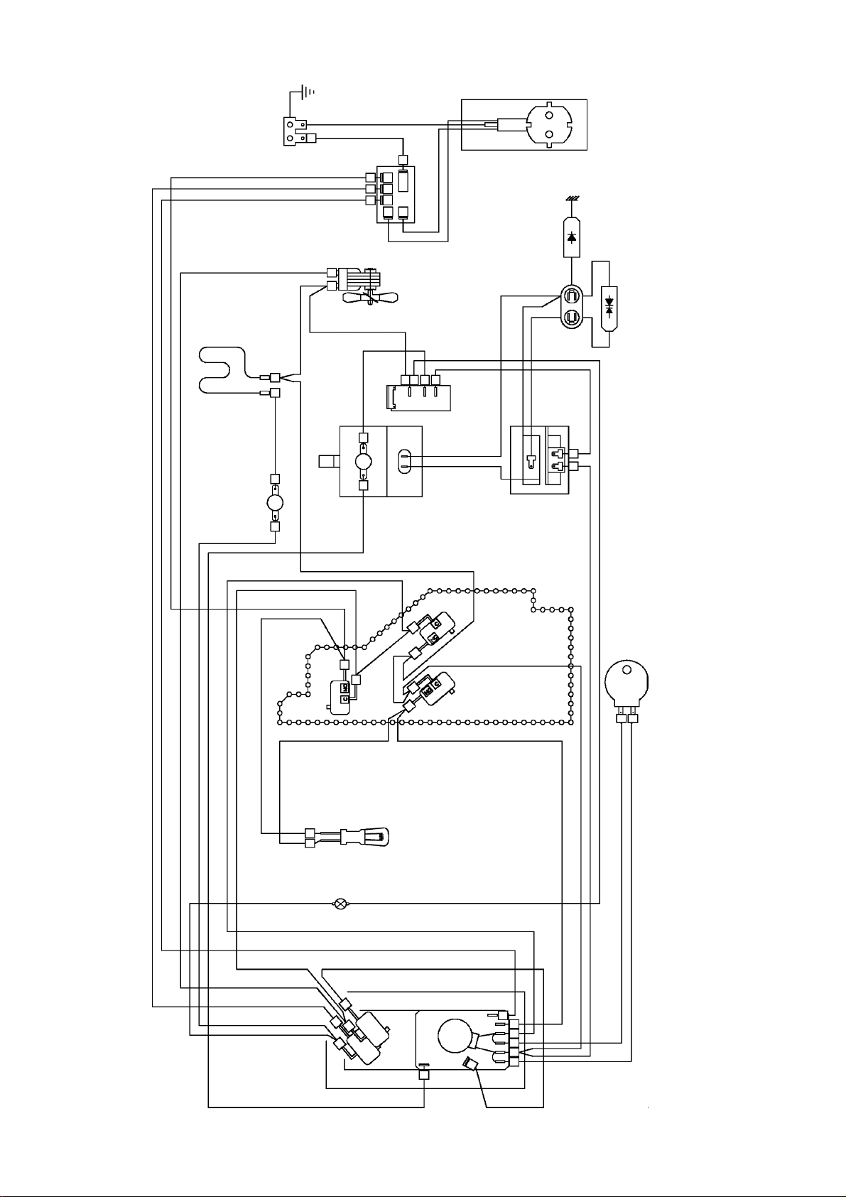
SCHEMA ELETTRICO / ELECTRIC DIAGRAM / SCHALTPLAN
SCHEMA ELECTRIQUE / ESQUEMA ELECTRICO
MARRONE
BIANCO
BLU
BIANCO
RG
BIANCO
THG
ROSSO ROSSO
FM
MGT
NF+F
ROSSO
MARRONE
S.LIM
TH.MGT
GIALLO / VERDE
CA
HVD
PDX
HVC
NERO
HVT
MARRONE
ROSSO
BIANCO
BIANCO
BLU
BIANCO
PRI
ROSSO
MARRONEMARRONE
OL
LSG
S1-S2
TIMER
DM
SEC MON
ROSSO
ROSSO
GRIGIO
GRIGIO
ROSSO
GRIGIO
3
SCHEDA TECNICA 97047
Colori Colours Farben Coleurs Colores
Bianco White Weiß Blanc Blanco
Blu Blue Blau Bleu Azul
Giallo-Verde Yellow/Green Gelb/Grün Jaune/Vert Amarillo/Verde
Grigio Gray Grau Gris Gris
Marrone Brown Braun Marron Castano
Nero Black Schwarz Noir Negro
Rosso Red Rot Rouge Rojo
Page 4

PRECAUZIONI DA ADOTTARE CERCANDO GUASTI
Adifferenza di altreapparecchiature, il fornoamicroonde èun'unitàad alto voltaggioed amperaggio.Nonostante ilsuo
normalenonpresenti alcuna pericolosità, si deveusareestrema cautela durante le riparazioni:
-Toglietevi l' orologiooperando inprossimitàdel magnetron.
-Attenzionealcondensatore ad alto voltaggio, potrebbe rimanere carico per circa 30 secondidopocheil forno ha
cessato di funzionare.
E'opportunoscaricarlo ogni volta collegandone entrambiipoli con la massa per mezzodiun cavetto adeguatamente
isolato.
-Icircuiti secondari del trasformatorepresentanocapacità di alto voltaggioedalto amperaggio, è quindi estremamente
pericolosolavorare nelle vicinanze diquesto componente quando ilforno è alimentato.
- Non toccare nessun filo con le mani o con attrezzi non isolati durante il funzionamento.
- Non eseguire misure di tensione sul circuito ad alto voltaggio e sul filamento del magnetron.
- Accertarsi che la porta non sia allentata o mancante. Se le viti non sono perfettamente strette ci possono essere
fughedimicroonde.
- Accertarsi che tutte le connessioni elettriche non siano lasche prima di laimentare il forno.
-Accertarsiche non siano fughe dimicroondeseguendo l' apposita procedura.
-Noninserirealcun ogetto mettalico attraverso le fessure della lampada oaltrefessuredella lampada o altre fessure
delforno,perchètali oggetti possono funzionare da antenna e causare fughedimicroonde.
ATTENZIONE
RADIAZIONIAMICROONDE
-LEPERSONENONDEVONOESSEREESPOSTEALL'ENERGIAAMICROONDECHEPUÒESSEREIRRADIATA
DALMAGNETRONODAALTRODISPOSITIVOGENERATOREDIMICROONDENELCASO DIUNA
UTILIZZAZIONEOCONNESSIONENONCORRETTA.
-TUTTE LECONNESSIONIA MICROONDEDI ENTRATA EDI USCITA,LEGUIDA D'ONDA,LEFLANGE EI
GIUNTIDEVONO ESSERE SICURI.
-NONFARFUNZIONAREILGENERATORESENZAUNCARICOPREVISTOPERASSORBIREL'ENERGIAA
MICROONDE.
-NONGUARDAREMAIALL'INTERNODIUNAGUIDAD'ONDAAPERTAODIUNAANTENNAMENTREIL
GENERATOREÈINFUNZIONE.
-NONFAR FUNZIONAREILFORNO,ENON PERMETTERELABENCHÈ MINIMAPOSSIBILITÀCHEILFORNO
POSSAFUNZIONAREAPORTAAPERTA
Eseguire i seguenti controlli di sicurezza su tutti i forni da riparare prima di attivare il magnetron o altro dispositivo
generatoredimicroonde, edeventualmenteeseguirelenecessarie riparazioni:
-Funzionamento del dispositivodichiusura.
-Coretta chiusura della porta.
- Stato della chiusura della guarnizione e delle superfici di battuta.
-Danneggiamento od allentamentodelle cerniere edegli agganci dichiusura.
-Segnievidentidi caduta od uso improprio.
Ognicomponentedifettoso o non correttamentetarato,posizionato nelle seguenti aree:chiusura,monitor,
guarnizione,porta, sistema digenerazionee trasmissione dellemicroonde deve essereriparato,sostituito,tarato.
ISTRUZIONIPERGLIINTERVENTISULMOTOREGIREVOLE
-Peraccedereal motore tranciare le linguette che mantengonoilcoperchio
delmotore(vedifig.A).
-Dopo l'interventorimontaretassativamente ilcoerchio co2viti
autofilettanti 4,2 x 9,5 senza punta.
A
4
SCHEDA TECNICA 97047
Page 5

MISURA DELLE MICROONDE DISPERSE
Ilcontrollo delle microondedispersedeve essere effettuatodopo ogni riparazione,
sostituzioneo regolazionedelle parti, del sistema di aggancio echiusura porta,del modulo
interruttori,delmagnetron.
-mettere un recipiente con 250cc di acqua al centro della
cavitàforno
-Accendere il forno allamassima potenza.
-Conun misuratore di campo per microonde a2.450MHZ,
controllareattentamenteledispersionimuovendo
lentamentela sonda lungoilperimetro di battutadella
portalungo le fughedel mobile. Perunacorretta
misurazioneattenersiscrupolosamentealleistruzionid'uso
dellostrumento.
- La dispersione massima ammessa è di 5 mW cm a 5 cm.
2
Normalmenteviene assicurata una dispersione piùbassa
delminimo consentito (<1mw/cm ).
2
MISURA DELLA POTENZA EMESSA DAL MAGNETRON.
NOTA: controllareil voltaggiodi alimentazione,se dovesseessere inferiorea 230V
la potenza emessa dal magnetron risulterà più bassa.
-Riempire l'apposito contenitorecon 1 litrod'acqua a temperaturanormale.
-Mescolarecoltermometro e rilevare la temperaturadell'acqua(T1).
-Posizionare il contenitoresul vassoio di vetroal centro del forno.
-Selezionare la potenzamassima e farfunzionare il fornoper 63 secondi.
-Mescolaredinuovo l'acqua col termometroerilevare la temperatura (T2).
-L'innalzamento termico deve essere circa10 -12°C.
-La potenza emessadal magnetron puòessere calcolata conla seguente
formula : P (W)=70 x(T2 - T1 ).
Sela potenza è inferiore al nomimnale di oltre il 15 %,sostituire il magnetron e verificare
lacapacità del condensatoreA.T.
5
SCHEDA TECNICA 97047
Page 6

PROCEDURADICONTROLLOCOMPONENTI
ATTENZIONE : Eseguire i test di continuità con la spina disinserita e dopo aver scaricato il
condensatorecortociquitando i terminali a massa con un cacciavite isolato
per 5000V. minimo
MAGNETRON
1) Scollegare il componente e collegare lo strumento ai terminali
del filamento : con il TESTER ohm x 1, la lettura deve risultare
inferiore a 1 ohm.
TRASFORMATORE
2) Scollegare tutte le connessioni del trasformatore con il
TESTER ohm x 1, le letture normali , a temperatura ambiente
dovrebbero essere :
2.1) Primario (vedi dati tecnici)
2.2) Filamento inferiore 1W
2.3) Secondario (vedi dati tecnici)
CONDENSATORE
ALTA TENSIONE 3) Scollegare tutte le connessioni del condensatore con il
TESTER ohm scala massima collegare lo strumento ai termi-
nali del condensatore : in primo momento si deve avere una
lettura come di continuità, che poi deve tornare a valore infinito.
3.1) La lettura tra ciascuno dei terminali e la cassa esterna deve
indicare un valore infinito.
Terminali
Cassa esterna
DIODO
ALTA TENSIONEALTA TENSIONE
ALTA TENSIONE
ALTA TENSIONEALTA TENSIONE
4 La continuità del diodo non si può misurare con un TESTER
mormale, in quanto presenta una caduta di tensione di 12V. Si
consiglia di collegare i terminali del diodo con una batteria ad 9 V
e una lampadina da 2,5 V collegata in serie.
.
- +
Batteria 9V
Lamp 2.5V
6
SCHEDATECNICA 97047
Page 7

COMMUTATORE / CHANGE OVER SWITCH / UMSCHALTER
COMMUTATEUR / CONMUTADOR
CHANGE OVER SWITCHCHANGE OVER SWITCH
CHANGE OVER SWITCH
AA
22
A
2
AA
22
CHANGE OVER SWITCHCHANGE OVER SWITCH
CONTACTS
A - 2
B - 3
B - 4
BB
33
3
33
44
B
4
BB
44
SHAFT POSITION
X
X
X
XX
PRECAUTIONS TO BE TAKEN WHEN TROUBLESHOOTING
Unlikeotherappliances, microwave oven is a high voltageandhighamperage unit. Even if you can useitnormally
withoutany danger,you shouldbe verycarefulduring maintenanceoperations:
-Takeoff your watch when operatingcloseto magnetron.
- Attention : the H.V. condenser could still be charged for about 30 seconds after the oven has been switched off.
It is advisable to discharge capacitor each time by both poles through a suitably insulated cable.
-Secondarycircuitsofthetransformerhaveahighvoltageandahighamperagecapacity,andthereforeitis extremely
dangerousto work near thiscomponentwhen oven is pluggedin.
-Nevertouch any wires with bare handsorwith no-insulated tools when oven isoperating.
-Do notmeasure voltageonhigh-voltage circuitor magnetronfilament.
- Make sure that door is not loose or missing. If screws are not perfectly tightened, it may lead to microwave leaks.
-Makesureallelectric connections are well tightened before turning on the oven.
-Make surethereis nomicrowaveleakage followingtheproper procedure.
- Do not insert any metal object either through lamp crevice or any other oven crevice as such objects could act as
anantennaandprovokemicrowaveleaks.
ATTENTION
Whenfusecutsblows,alwayscheckprimary,secondary,monitorandextramicroswitchesefficiency,beforeturning
theovenon.Should a microswitch be found defective, always change all microswitches.
ATTENTION: MICROWAVERADIATION
-PERSONNELSHOULDNOTBEEXPOSEDTO MICROWAVEENERGY WHICHMAYRADIATEFROMTHE
MAGNETRONOROTHERMICROWAVEGENERATINGDEVICEIFITISIMPROPERLYUSEDORCONNECTED.ALL
INPUT AND OUTPUT MICROWAVE CONNECTIONS, WAVEGUIDES, FLANGES AND GASKETS MUST BE
SECURE.
-NEVEROPERATETHEDEVICEWITHOUTAMICROWAVEENERGYABSORBINGLOAD,INSIDETHEOVEN
CAVITY.
-NEVERLOOKINTOANOPENWAVEGUIDEORANTENNAWHILETHEDEVICEISWORKING.
-NEVER OPERATEOR ALLOWTHEOVEN TOBE OPERATEDWITH THEDOOROPEN .
Make the following safety checks on all ovens to be serviced before activating the magnetron or other microwave
source, and make repairs as necessary :
-Interlockoperation.
-Proper door closing.
- Seal and sealing surfaces state
-Damageorloosening of hinges and latches,
-Evidenceofdroppingorabuse.
Any defective or misadjusted components in the interlock, monitor, door seal and microwave generation and
transmission systems shall be repaired, replaced, or adjusted .
INSTRUCTIONSFORMAINTENANCEONTURNTABLEMOTOR
-To reach the motor, cut the metal reeds that retain
the motor cover (see fig. ).
-Aftertheoperationset back the motor cover and
fix it with 2 self-threaded screws 4.2x9.5 with no sharp end.
7
SCHEDA TECNICA 97047
Page 8

MICROWAVE LEAKAGE TEST
This test has to be done after every manteinance operation regarding the door and the
whole closure system, microswitches and magnetron.
Testequipment:
- 600 ml beaker
- Microwavesurveymeter
Testprocedure:
- Place 250 mlwater in a beaker and place itin the centre of the oven
- Turn on oven, settimerfor5minutesatfullpower
- Hold theprobeof the microwavesurveymeter perpendicular to thedooredge of the
ovenandscanitveryslowly.
Testthefollowingareas:
- Door andcontrolpanel
- Allventilationopenings
- All lockseams
- Weld at borrom
- Bottom plate
Operations:
- Open thedoorto the position atwhichtheoven is justabouttoturn off, scan thedoor
perimeter.
- The distance between door and probe must beat
least 5 cm
- Maximum allowable leakage is 4 mW / cm
2
MAGNETRON POWER TEST
Thestandardtestloadis one litre (1000ml)waterwithaninitial temperature of 15-24°C(58- 75
°F)ina1000mlbeaker.Donotuseanyotherloadordishotherwisetestresultwillvaryfromstandard.
Testprocedure:
- Measure andadjustthevoltageof the AC power supplytoitscorrectvalue.
Bearinmind thattestresultisinfluencedby thevoltagesupplyvalue.
Toolowortoohighvoltagewillnot determine an accurate measurement.
- Place beaker containing exacly 1000 mlwater at15 - 24 °C in the centreof theoven.
UseanaccuratethermometertoreadtheinitialwatertemperatureT1.
- Set the appliance for63 seconds atfull power.
- At theend of this period,stir the waterquicklyand read thewater final temperature T2.
ThedifferencebetweenthefinaltemperatureT2andtheinitialtemperatureT1isthe
temperaturerise.
Result:
- The microwave power oftheovencanbedeterminedbythefollowingformula:
P (W) = 70 x (T2 - T1)
If power is more than 15% off the nominal power of the M.W., then verify High Voltage
Capacitor and eventually change magnetron.
8
SCHEDA TECNICA 97047
Page 9

COMPONENTS TEST PROCEDURE
MAGNETRON 1. Chek resistance: Normalreading:
Across the filament terminals Less than 1 Ohm
of the magnetron with an Ohmmeter on R x 1 scale.
2. Chek resistance: Normalreading:
between each filamet terminals infiniteOhm
of the magnetron and the chassis
ground with an ohm-meter set on
highest scale
HIGH VOLTAGE 1. Measurement the resistance: Normal reading:
TRANSFORMER with ohm-meter onRx1scale.
a) Primary winding: - appoximately 1.24 Ohm
b) Filament winding: - less than 1 Ohm
c) Secondary winding: - appoximately 87 Ohm
2. Measure the resistance: Normal reading
with an ohm-meter on highest scale
a) primary winding to ground - infinitive Ohm
b) Filament winding to ground - infinitive Ohm
HIGH-VOLTAGE 1.Measurethe resistance: Normalreading:
CAPACITOR Across the terminals of the Momentarilyindicatesseveral
capacitorwith an ohm-meteron Ohm,andthen graduallyreturns
highest scale. to infinite Ohm.
Abnormalreading:
indicates continuity or infinite
Ohmfromthe beginning.
Terminals
External housing
CAUTION: discharge high voltage capacitor before cheking parts of high voltage circuit.CAUTION: discharge high voltage capacitor before cheking parts of high voltage circuit.
CAUTION: discharge high voltage capacitor before cheking parts of high voltage circuit.
CAUTION: discharge high voltage capacitor before cheking parts of high voltage circuit.CAUTION: discharge high voltage capacitor before cheking parts of high voltage circuit.
DIODE
1. Check diode:
Across the terminals with a 9V
battery and 2.5V lamp circuit.
- +
Lamp 2.5V
9
Normal reading:
Lamp is ONor OFFdepending
onpolarityof voltage.
Abnormal reading:
Lamp is too bright : short circuit
Lamp is never ON : open circuit
SCHEDA TECNICA 97047
 Loading...