

Page 1
1
Summary and features
SOLEUSAIR
Model Remarks
KFIHP-09
KFHHP-12 1Ph,208-230V,60Hz,R410A
1Ph,115V,60Hz,R410A
Page 2

Specifications and technical parameters
2
Model
Function
Rated Voltage 115V
Frequency(Hz) 60HZ
Rated Capacity (Btu/h)
Rated Input (W) (High/Standard) 1200/730 1400/800
Rated Current (A)
Air F low Volume (m
Dehumidifying Volume (l/h) 1.2
Model of Indoor Unit
Fan Motor Speed ( r /min)
(H/M/L)
Output of Fan Motor (w)
Input Power of Heater (w)
Fan Motor Capacitor (uF) 1.0
Fan Motor RLA(A) 0.14
Fan Type-Piec e
Diameter-Length (in) 3.8-23
Evaporator
Pipe Diameter (in) 0.28
Indoor
Row-Fin Gap(in) 2-0.055
Coil length (l) x height (H) xcoil
unit
width (L)(in)
Swing Mot or Model
Output of Swing Mot or ( W)
Fuse (A)
Sound Pr essure Lev el dB ( A)
(H/M/L)
3
/h) (H/M/L)
COOLING HEATING
10400 12800
6.4 7
KFIHP-09
600
KFIHP-09ID
1160/1010/890
14
/
Cross flow fan – 1
φ
Aluminum fin-c opper tube
Φ
22.83x9x1
MP28VA
2
PCB3.15A transformer0.2A
40/ 36/ 33
Dimension (W/D/H)( in)
Dimension of Pack age
(W/D/H)( in)
Net Weight /Gross Weight (lb)
32.67×8.86×11.22
33.66×10.7×13.22
18.7/27.6
2
Page 3
Coil
length
(l)xheight
(H)xcoil
width
(L)(in(i(
SOLEUSAIR
Outdoor
unit
Model of Outdoor Unit
Compressor Manufact ur er /tr ademark
Compre ssor Model
Compre ssor Type
L.R.A. (A)
Compressor RLA ( A)
Compressor Power Input(W)
Overload P r otect or
Thr ottling Method
St ar ting M ethod
Wor k ing Temp Range (ć)
Condenser
Pipe Diameter (in)
Rows-Fin Gap(in)
Fan Motor Speed (rpm)
Output of Fan Motor ( W)
Fan Motor RLA(A)
Fan Motor Capacit or ( uF)
Air Flow Volume of Outdoor Unit
Fan Type-Piece
Fan Diameter (in)
Defr osting Method
Climate Type
Isolation
M oisture Protection
Permissible Excessiv e Operat ing
P re ssur e for the Disc harg e
Permissible Excessive Operating
Sound Pr essure Lev el dB ( A) ( H/M /L)
KFIHP-09OD
SANYO
C-6RZ092H1AB
Twin rotory
33
3.92
960
Int11l-3979
Capillary t hr ottling
Tr ansducer star ting
-7ćİTİ43
Aluminum fin-c opper tube
2-0.05
25.4X20X1.73
830±20
1800
Axial fan –1
Auto defrost
ć
0.37
30
0.3
2.5
15.75
T1
I
IP24
3.8
1.2
55
Dimension (W/D/H)( in)
Dimension of Pac k age ( W/D/H)( mm)
Net Weight /Gross Weight (lb)
Refrigerant Charge (oz)
Length (ft)
Connec
Gas additional charge(oz/ft)
tion
Outer Diameter
Pipe
Max Distance
If there are any changes in the specifications and parameters in the above table, Please refer to the nameplate of the unit.
Liquid Pipe (mm)
Gas Pipe (mm)
Height (ft) 39
Length (ft) 66
33.38X12.6X21.27
34.6X14.2X23.2
88.18/99.2
R410A / 42
26
0.22
Φ6(1/4”)
Φ12(1/2”)
Page 4
Specifications and technical parameters
2
Model
Function
Rated Voltage 208V230V
Frequency(Hz) 60HZ
Rated Capacity (Btu/h)
Rated Input (W) (High/ Standard)
Rated Current (A)
Air F low Volume (m
Dehumidifying Volume (l/h) 1.2
Model of Indoor Unit
Fan Motor Speed ( r /min)
(H/M/L)
Output of Fan Motor (w)
Input Power of Heater ( w)
Fan Motor Capacitor (uF)
Fan Motor RLA(A)
Fan Type-Piec e
Diameter-Length (in)
Evaporator
Pipe Diameter (in)
Indoor
Row-Fin Gap(in)
Coil length(l) x height (H) xcoil
unit
width (L)(in)
Swing Mot or Model
Output of Swing Mot or ( W)
Fuse (A)
Sound Pr essure Lev el dB ( A)
(H/M/L)
3
/h) (H/M/L)
COOLING HEATING
13200 15900
1450/1100 1500/1200
5 5.45
KFHHP-12
600
KFHHP-12ID
1350/1200/1110
22
/
1
0.152
Cross flow fan – 1
φ3.63—24.3
Aluminum fin-c opper tube
Φ0.27
2-0.05
26.8×12.76×1.5
MP28EA
2
Contr oller 3. 15 transformer0. 2
43 / 40 / 39
Dimension (W/D/H)( in)
Dimension of Pack age
(W/D/H)( in)
Net Weight /Gross Weight (lb)
32.7×8.86×11.2
34.4×12.3×14.6
24.3/33
6
Page 5

Coil
length
(l)xheight
(H)xcoil
width
(L)(in(i(
SOLEUSAIR
Outdoor
unit
Connec
tion
Pipe
Model of Outdoor Unit
Compressor Manufact ur er /tr ademark
Compre ssor Model
Compre ssor Type
L.R.A. (A)
Compressor RLA ( A)
Compressor Power Input(W)
Overload P r otect or
Thr ottling Method
St ar ting M ethod
Wor k ing Temp Range (ć)
Condenser
Pipe Diameter (in)
Rows-Fin Gap(in)
Fan Motor Speed (rpm)
Output of Fan Motor ( W)
Fan Motor RLA(A)
Fan Motor Capacit or ( uF)
Air Flow Volume of Outdoor Unit
Fan Type-Piece
Fan Diameter (in)
Defr osting Method
Climate Type
Isolation
M oisture Protection
Permissible Excessiv e Operat ing
P re ssur e for the Disc harg e
Permissible Excessive Operating
Sound Pr essure Lev el dB ( A) ( H/M /L)
Sound Power Level dB ( A) ( H/M/L)
Dimension (W/D/H)( in)
Dimension of Pac k age ( W/D/H)( mm)
Net Weight /Gross Weight (lb)
Refrigerant Charge (oz)
Length (ft)
Gas additional charge(oz/ft)
Outer Diameter
Max Distance
KFHHP-12OD
SANYO
C-6RZ092H1AB
Twin rotory
33
3.92
960
Int11l-3979
Capillary t hr ottling
Tr ansducer star ting
-7ćİTİ43
Aluminum fin-c opper tube
2-0.05
25.4X20X1.73
830±20
1800
Axial fan –1
Auto defrost
33.38X12.6X21.27
34.6X14.2X23.2
88.18/99.2
R410A / 44
Liquid Pipe (mm)
Gas Pipe (mm)
Height (ft)
Length (ft)
ć
0.37
30
0.3
2.5
15.75
T1
I
IP24
3.8
1.2
55
65
26
0.22
Φ6(1/4”)
Φ12(1/2”)
39
66
If there are any changes in the specifications and parameters in the above table, Please refer to the nameplate of the unit.
7
Page 6
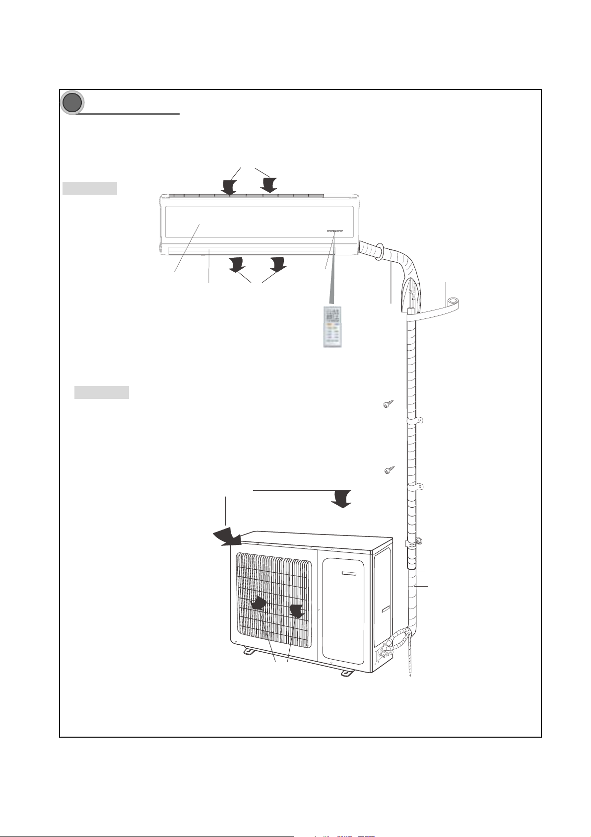
Part name
3
Indoor Unit
Air inlet
Front panel
Outdoor Unit
Guide louver
Air inlet
Receiving window
Air outlet
Wireless remote controll
wrapping tape
LED board
Air outlet
Bjs!Pvumfu
Drainage hose
Dpoofdujpo!qjqf
boe! dpoofdujpo! xjsf
Connecting pipe and connection wire
ü8ü
Page 7
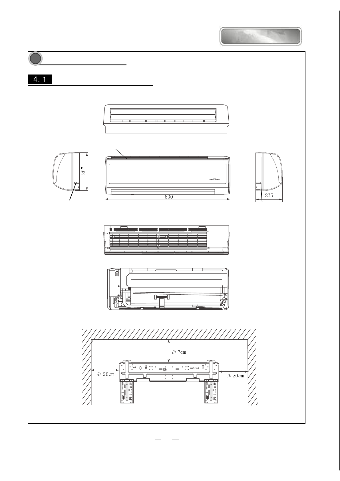
Overall and Installing Dimension
4
UOverall and Installing Dimension of Indoor Unit
Air inlet grill
SOLEUSAIR
Left piping hole
Right piping hole
Top view
Unit˖mm
Rear view
Wall-mounting plate
9
Page 8
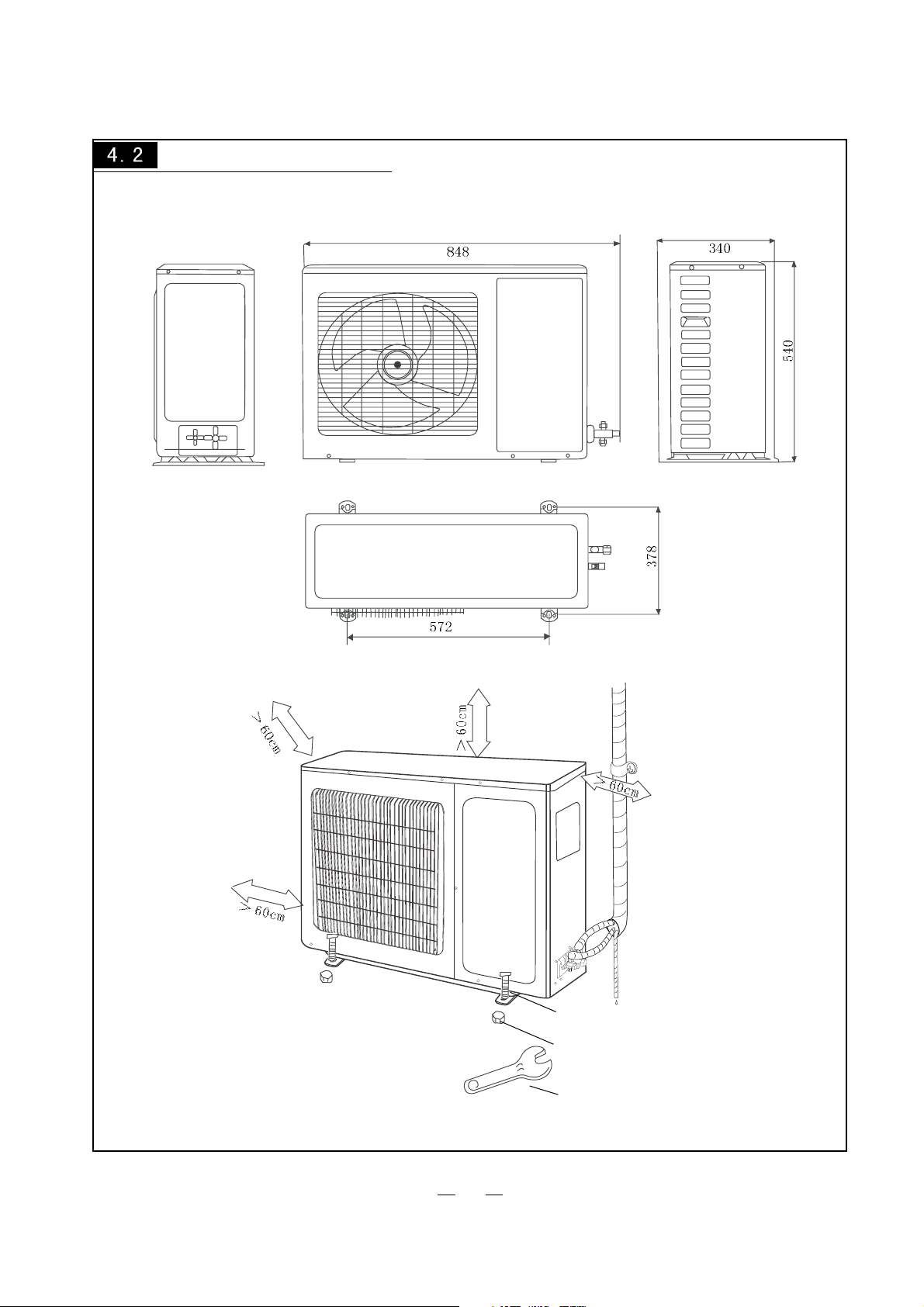
U
Overall and Installing Dimension of Outdoor Unit
Bolt
Nut
Wrench
Unit: mm
10
Page 9
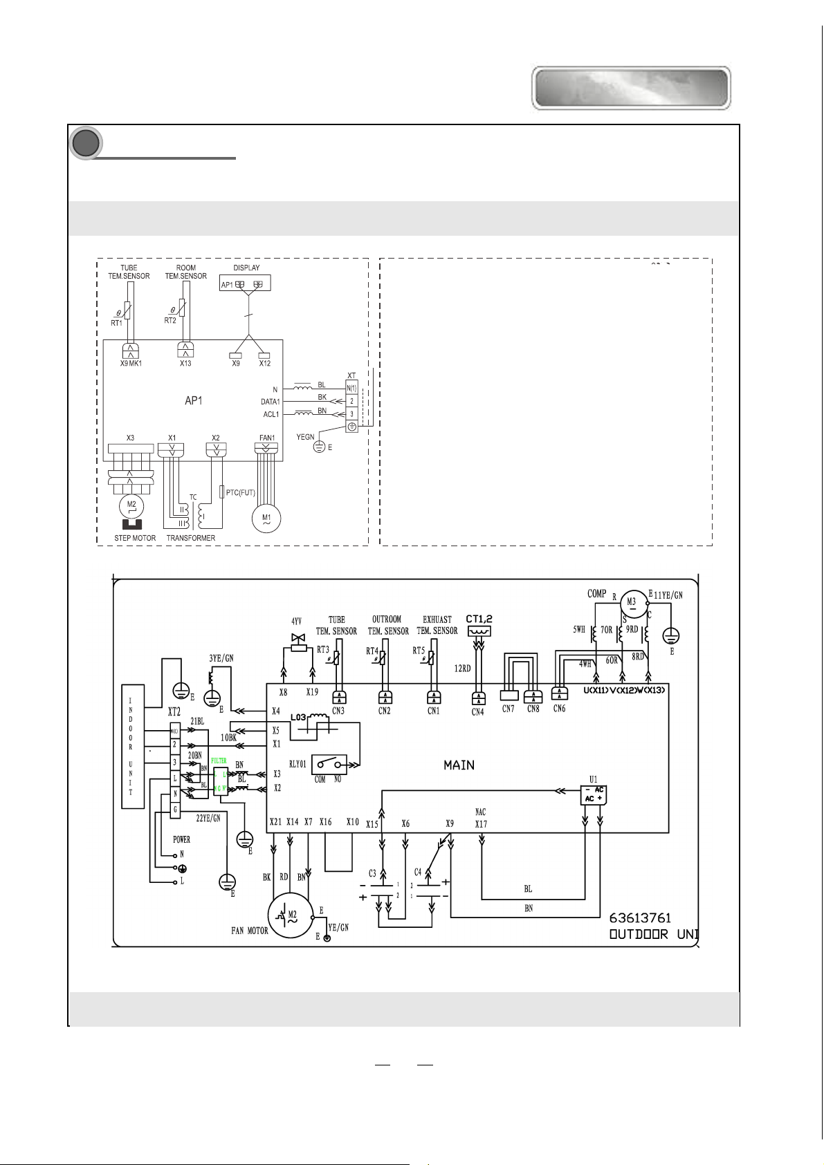
Circuit Diagram
KFIHP-09
SOLEUSAIR
INDOOR UNIT
These circuit diagrams are subject to change without notice. Please refer to the ones stuck on the machines.
11
Page 10
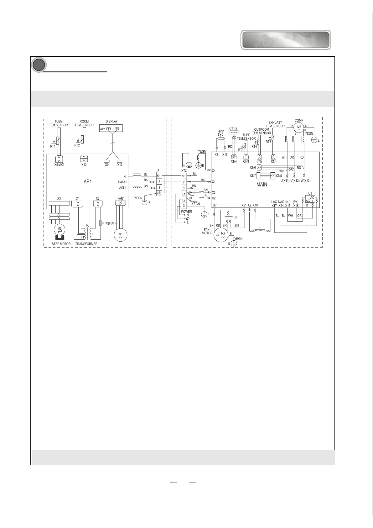
Circuit Diagram
5
KFHHP-12
SOLEUSAIR
INDOOR UNIT OUTDOOR UNIT
These circuit diagrams are subject to change without notice. Please refer to the ones stuck on the machines.
12
Page 11

Function manual and operation method of remote controller
66
6
66
Function manual of remote controller
This function manual is applicableto D.C. Variable Frequency
6.1.1 Temperature parameters
ƹ Room set temperature (T
ƹ Room ambient temperature (T
6.1.2 Fundamental functions
After powered on, no matter when the compressor is started, the time interval between two startups
cannot be less than 3 minutes.
6.1.2.1 COOL mode
6.1.2.1.1 The condition and process of cooling
If T
ambTset
, COOL mode will act, the compressor and outdoor fan will run, and the indoor fan will run at the set
speed.
If T
ambTset
-2 , ć the compressor will stop, the outdoor fan will delay 30 seconds to stop, and the indoor fan will
run at the set speed.
-2ć˘T
If T
set
In this mode, the reversal valve will not be powered on and the temperature setting range is 16ć~30 .ć
The unit will adjust the running frequency of the compressor automatically according to the change of ambient
amb˘Tset
, the unit will keep running in the previous mode.
temperature.
6.1.2.1.2 Protection function
ƹ Antifreezing protection
Under cooling and drying mode, after the compressor run about 10mins,when the pipe temp.of the
evaporator is to low, the compressor will stop, the outdoor fan will stop after 30s, under cooling
mode the indoor fan and swing motor will keep running in the original mode , under drying mode the
indoor fan will run at low fan speed, the swing motor will run in the original mode. When antifreezing
protection is eliminated and the compressor has stopped for 3 minutes, the unit will resume running in
the original mode.
)
set
)
amb
Tset
Tset
Compressor
Outdoor fan
Indoor fan
Tamd
Set fan speed
Run
3min
Stop
Theperiod of antifreezingprotection
Start cooling
Original running state
Stop cooling
ƹ Overcurrent protection
Compressor
Outdoor fan
Indoor fan
Run
ı3 min
Stop
If total current is high, the compressor will run in limited or dropped frequency. When total current goes on
rising over the stated value, the compressor will stop, the outdoor fan will delay 30 seconds to stop.
6.1.2.2 DRY mode
6.1.2.2.1 The condition and process of drying
15
Page 12

d
SOLEUSAIR
If T
amb>Tset
, DRY mode will act, the indoor fan, outdoor fan and compressor will run, and indoor fan will run at
low speed
If T
If T
-2 ć T
set
amb<Tset
ambTset
-2 , the compressor will stop running, the outdoor fan will delay 30 seconds to stop and the indoor ć
, the unit will keep running in the original mode.
fan will run at low speed.
¾In this mode, the reversal valve will not be powered on and the temperature setting range is 16ć~30ć.
The unit will adjust the running frequency of the compressor automatically according to the change of ambient
temperature.
T
set
Compressor
Outdoor fan
Indoor fan
6.1.2.2.2 Protection
Protection is the same with that in COOL mode.
T
-2Ɔ
T
amb
set
Low fan spee
Run
Stop
Dry mode will act
Running in the original mode
Stop running
6.1.2.3 HEAT mode
6.1.2.3.1 The condition and process of heating
If T
ambTset
+2ć, HEAT mode will act, the compressor, outdoor fan and 4-way valve will run simultaneously,
the indoor fan will delay at most for 2min to run.
If T
If T
+2ć⧞T
set
ambTset
amb⧞Tset
+5 , the compressor will stop, the outdoor fan will delay 30sec to stop and the indoor fan will blow ć
+5ć,the unit will keep running in the original mode.
for 60sec at the original speed and then stop.
¾In this mode, the temperature setting range is 16ć~30ć.
¾The air conditioner will adjust the running frequency of the compressor automatically according to the change
of ambient temperature.
¾When the unit is turned off in HEAT mode, or switched to other mode from HEAT mode, the four-way valve
will be powered off 2min later after the compressor stops.
Tset
Stop heating
Original running state
Tset
Start heating
6.1.2.3.2 The condition and process of defrosting
Compressor
Outdoor fan
Indoor fan
Reversal valve
Tamb
2min 2min
3min
Run
Stop
When frost is detected in the condenser, the system will enter into defrosting state. When defrosting starts, the
compressor and indoor fan will stop, and the outdoor fan and four-way valve will delay 30 seconds to stop. The
compressor will start again after 30s and. When the compressor has run for 8mins, the compressor will stop.
After 30 seconds the four-way valve opens and after another 60 seconds, the compressor and outdoor fan resume
running. The indoor fan will delay 2 minutes to run at the latest and temperature on the display panel shows H1.
Under heating mode,when the compressor is stopped by malfunction, the indoor fan will blow at low fan speed for
60s and then stop.
6.1.2.3.3 Protection
Overcurrent protection
If total current is high, the compressor will run in limited or dropped frequency. When total current go on rising
16
Page 13

over the stated value, the compressor will stop, the outdoor fan will delay 30 seconds to stop.
set
6.1.2.4 FAN mode
In this mode, the indoor fan will run the fan in High, Med, Low and Auto mode. The compressor, outdoor fan
and four-way valve will stop.
In this mode, the temperature setting range is 16~30 .
The unit will adjust the running frequency of the compressor automatically according to the change of ambient
temperature.
6.1.2.5 AUTO mode
In this mode, the system selects COOL, HEAT and FAN mode automatically according to the change of ambient
temperature. The protection function is the same with that of COOL/HEAT mode.
The unit will adjust the running frequency of the compressor automatically according to the change of ambient
temperature.
6.1.3 Other control
6.1.3.1 ON / OFF
Each time the On/Off button of the remote controller is pressed, the On/Off state will switch once.
6.1.3.2 MODE selection
Press the MODE button on the remote controller to select and display the following modes:
AUTO, COOL, DRY, FAN, and HEAT.
6.1.3.3 TEMP. setting button
Each time TEMP + or TEMP - button is pressed, the set temperature will be increased or decreased by 1 .
Adjusting range is 16~30 . In AUTO mode, this button does not function.
6.1.3.4 AUTO key
When the unit is stop, press AUTO key,the unit will run under AUTO mode and the swing motor starts.
When the unit is running, press AUTO key,the unit will be stopped.
AUTO/STOP
6.1.3.5 Timer control
The unit is turned on or off according to the timer set by the remote controller.
6.1.3.6 Sleep control
When the air conditioner is in COOL or DRY mode, after Sleep mode has been set properly, the preset T
be increased by 1 after the sleep programć has run for 1 hour, and T
hours. T
has been increased by 2 totally in two hours. Then the unit will run at this set temperature and at ć
set
will be increased by another 1 after 2 ć
set
the set speed.
T
+2ć
T
+1ć
T
set
1 h 2 h Above 2h
Set temp.T
set
When the air conditioner is in HEAT mode, after Sleep mode has been set properly, the preset T
decreased by 1 after the sleep program has run for 1 hour, and Tć
hours. T
has been increased by 2 totally in two hours. Then the unit will run at this setć temperature and at the
set
set speed.
1 h 2 h Above 2h
T
set
-1ć
T
will be decreased by another 1 after 2 ć
set
Handling switch
will
set
will be
set
T
-2ć
Set temp.T
set
In AUTO or FAN mode, the setting temp. will not change.
17
Page 14

SOLEUSAIR
6.1.3.7 Indoor fan control
Use the remote controller to set the indoor fan running at HIGH, MED or LOW speed. At this time the fan will run
at high, medium or low speed. It can also be set to AUTO and the indoor fan will select fan speed(HIGH, MED or
LOW) automatically according to ambient temperature.
There are at least 3mins and 30s delay for fan speed shift.
6.1.3.8 Power supply for outdoor unit
The power supply for outdoor unit is turned on in AUTO, COOL, HEAT and DRY mode under turn-on state.
The power supply for outdoor unit will delay 3 minutes to turn off under turn-off state or in the FAN mode under
turn-on state.
6.1.3.9 Swing control
Use the SWING button of the wireless remote control to control SWING On and Off. Swing will only act when
indoor fan is running.After power on, the swing motor turns back to 0 position and closes the air outlet vent; if it
does not preset swing, after the unit is turned on, it will turn to the max. air outlet D1 position; then turn back to L
position under COOL mode.Under HEAT mode,the guide louver stays at D1;when in swinging state, it will swing
between L1 and D1 position. When the unit is turned off, it will turn back to 0 position.
6.1.3.10 Buzzer control
When the unit is power on or receives remote control signal or the auto key be pressed,the buzzer will give out a beep.
6.1.3.11 Power-off memory function
Contents of memory: Mode; Swing; Set fan speed, Set temperature,Timing etc.
Under turn-on state, when power off and power on, the power supply for outdoor unit will be turn on after 3mins .
Under turn-off state, when power off and power on, the power supply for outdoor unit will be turn on immediately.
6.1.3.12 Delay Protection of Compressor
Under COOL; DRY; HEAT mode, before each time the compressor starts, there will be 3mins delay.
6.1.4. Common protection function in each mode
6.1.4.1 Overload protection
T
tube:at cooling,it detects the temp. of outdoor heat exchanger,at heating,it detects the temp. of indoor heat exchanger.
When Ttube is detected high, the compressor will run in limited frequency.When Ttube goes on rising over the stated
value, the compressor will stop, under AUTO HEAT or HEAT mode, indoor fan will blow 60s at low fan speed and
then stop, under other mode, the indoor fan will run at set speed.
6.1.4.2 Compressor discharge temperature protection
When discharge temperature is too high to over the stated value, the compressor will stop, and When discharge temp.
resume normal and the compressor has stopped for 3 minutes, the unit will resume its original operating status.
6.1.4.3 Communication malfunction
When not receiving correct signal for 3 minutes, the unit has communication malfunction and the outdoor unit
stops, it is the same as normal stop when meeting the set temp..
6.1.4.4 Module protection
When module is in protection, the compressor will stop, after the compressor has stopped for 3 minutes, it will
resume to running. During module protection period, the indoor unit displays malfunction and the whole unit stops.
18
Page 15

Disassembly procedures
77
7
77
Disassembly procedures for indoor unit
Operation procedures/pictures
8.1.1 Disassembling the front panel and
electric box cover
Unloose the clasps on both sides and lift the panel
upward. Unplug the two connecting terminals of the
display and slide out the rear clasp from the groove to
take off the front panel.(you can use panel support bar
to support the panel) Screw off the fixing screws of
the electric box cover and open the electric box top cover to take it off.
As shown in Fig.7-1
Filter
Panel
panel support bar
Fig.7-1
Screw
Electric box
top cover
Push the filter up to unloose the clasp to pull out the
two filters.
8.1.2
As shown in Fig.7-2
Disassembling the guide louver
Bend the guide louver with strength and let out the
rotating shaft from the groove to take off the guide
louver. As shown in Fig.7-3
Filters
Fig.7-2
Guide louver
Fig.7-3
19
Page 16

Operation procedures/pictures
Disassembling the front panel body
Unclench the 3 screw covers and screw off the 3 pieces
of screws that fix the panel body. Unloose the front and
rear clasps to take off the panel body.
As shown in Fig.7-4
Disassembling the electric box cover
Unloose the 3 clasps to take off the electric box cover.
As shown in Fig.7-5
screw
SOLEUSAIR
screw covers
Fig.7-4
Disassembling the water-tray assy
Unloose the clasp on the left side and unplug the
connecting terminal of the stepping motor. Carefully
to remove the water-tray assy because the drainage pipe
is placed here. As shown in Fig7-6, 7-7
water-tray assy
cc
connecting terminal
cl
clasps
Fig.7-5
clasp
Fig.7-6
Fig.7-7
20
Page 17

Operation procedures/pictures
7.1.7 Disassembling the electric box
Screw off the two pieces of screws that fix the electric
box and unloose the clasp. Pull out the tube sensor,
unloose the grounding nut and unplug the motor
connecting terminal take out the electric box.
As shown in Fig 7-8
7.1.8 ||||||||| Disassembling the evaporator assy
Screw off the screws that fix the evaporator, one piece
on the left and two pieces on the right. As shown in Fig
7-9, 7-10
Lift the left end of the evaporator slightly upward with
your end and push it rearward to let out the side clasps
of the evaporator from the groove. Take out the
evaporator carefully and pay attention to protecting the
connecting pipe.
Tube sensor
Screws
Grounding nut
Motor connecting
terminal
Fig 7-8
Screw
Fig 7-9
Screws
7.1.9
Disassembling the motor
Screw off the 3 pieces of screws that fix the motor
clamp to take off the motor clamp. As shown in Fig.7-
11
Screw off the fixing nut that fixes the cross flow fan to
pull out the motor from the cross flow fan. As shown in
Fig.7-12
7.1.10
Disassembling the cross flow fan
Refer to the above steps to take out the cross flow fan
from the base plate after taking out the motor.
s
Fig 7-10
Screws
Right motor
clamp
Fig 7-11
screws
motor
cross flow fan
Fig 7-12
21
Page 18

Disassembly Procedures for Outdoor Unit
Operating Procedures / Photos
Disassemble Top Cover and Handle
Use screwdriver to unscrew the screw at the
handle, and remove the handle. Unscrew the three
screws around the top cover, and remove the top
cover.
(refer to Figure 7-13)
SOLEUSAIR
Disassemble Rear Grill
Screw out the 4 self tapping screws on
rear side plate and chassis of valve supporter
and side plate of condenser can take off rear grill.
(refer to Figure 7-14)
2 Disassemble Components of Panel
Screw out the 5 tapping screws on panel and
chassis of valve supporter and side plate of condenser
can take off components of panel.
(refer to Figure 7-15)
Top Cover
screw
Grill
Panel
screw
screw screw
Figure 7-14
Handle
Figure 7-13
22
Figure 7-15
Page 19

Operating Procedures / Photos
Disassemble electric install plate
Screw out the 3 bolts that fixing on electric install
plate, plug out lead inserter of compressor and
fan to take off electric install plate.
(refer to Figure 7-16,7-17)
electric box cover
bolts
Figure 7-16
Disassemble Right Side Plate
Screw out the 5 bolts on rear side plate can take
off right side plate.
(refer to Figure 7-18)
Disassemble axial-flow vane
Loosen tighten nut by spanner to take off nuts,
spring washer, flat washer, and take off axial-flow
vane forcibly.
(refer to Figure 7-19)
tighten nut
bolts
bolts
Figure 7-17
Figure 7-18
axial-flow vane
23
Figure 7-19
Page 20

Operating Procedures / Photos
Disassemble Motor and Motor Support
Unscrew the four tapping screws fixing the motor,
and remove the motor. Unscrew the two tapping
screws fixing the motor support, and lift the motor
support to remove it.
SOLEUSAIR
Motor Support
tapping screws
(refer to Figure 7-20)
Disassemble 4-Way Valve
Screw off the holding nut of the 4-way valve coil
and remove the coil. Use wet cotton cloth to wrap
the 4-way valve, unsold the four soldering points
connecting the 4-way valve, and remove the
soldering points
4-way valve. Be quick during the unsoldering
process, pay attention to keep the wrapping cloth
wet and do not allow the soldering flame to burn
the compressor lead-out cable.
(Note: only after discharging all freon).
(refer to Figure 7-21)
Disassemble Capillary Subassembly
Motor
Figure 7-20
4-way valve
holding nut
Figure 7-21
Unsolder the soldering points connecting the
capillary subassembly and the other pipelines, and
remove the capillary subassembly.
(refer to Figure 7-22)
24
Capillary Subassembly
Figure 7-22
Page 21

Operating Procedures / Photos
Disassemble Valves
Unscrew the two screws fixing the big valve,
unsolder the soldering point between the big
valve and the return-air duct and remove the big
valve.
(Note: when unsoldering the soldering point, use
wet cloth to completely wrap the big valve to
prevent valve body from being harmed by high
temperature.)
Unscrew the two screws fixing the small valve,
unsolder the soldering point connecting the small
valve and the fork type pipe, and remove the small
valve.
(refer to Figure 7-23)
Disassemble Compressor
Unscrew the three nuts with washers at the foot of
the compressor. Unsolder the soldering points at
the suction and the discharge pipes of the compressor,
carefully remove the pipes and take out the
compressor.
Small Valves
Big Valves
bolts
Figure 7-23
(refer to Figure 7-24)
Figure 7-24
compressor bolt
25
Page 22

Exploded View and Components and Parts List
8
Exploded View of Components and Parts of Indoor Unit
KFIHP-09 KFHHP-12ID
SOLEUSAIR
26
Page 23

Components and Parts List of Indoor Unit
No Description Qty
1 Wall-Mounting Frame 01252220 1
2Rear Case
3 Evaporator Assy 01002070 1
4 Cross-Flow Fan 10352001 1
5 Ring of Bearing 76712203 1
6 Drain Hose 05232411 1
7 Water Tray 20182070 1
8 Swing Louver 10582002 1
9 Swing Linkage
10 Front Grill 01472005 1
11 Front Case 20002210 1
12 Screw Cap 24252006 3
13 Air Filter 11122002 2
14 Panel 20002812 1
15 Panel 20002814 1
16 Remote Control 30511010 1
17 Light Cover 22242031 1
18 Display Board 30545706 1
19 Display Cover
20 Shield Board 26112044 1
21 Guide Louver 26112033 1
22 Guide Louver 26112034 1
23 Step Motor 15212110 1
24 Right Motor Clamp
25 Motor
26 Motor Bearing Holder
27 Electric Box 201021781 1
28 Electric Box Cover 22242030 1
29 Terminal Board
30 Covering Plate
31 Main PCB
32 Room Sensor
33 Tube Sensor
34 Transformer
35 Wir e Clamp
36
Rear Clamp 26112430
Part Code
KFIHP-09ID
222020012
150121082
42011233
201220064
30039146
390000451
390000591
43110254 1
71010003
1
1
1
1
1
1
1
1
1
1
1
1
1
27
Page 24

Components and Parts List of Indoor Unit
No Description Qty
1 Wall- Mount ing Frame 01252384 1
2Rear Case
3 Evaporator Assy 010021811 1
4 Cross-F low Fan 10352005 1
5 Ring of B ear ing 76712015 1
6 Drain Hose 05232411 1
7 Water T r ay 201820302 1
8 Swing Louver 10512041 1
9 Swing Linkage 10582439 1
10 Fr ont Gr ill 01472004 1
11 Fr ont Case 20002295 1
12 Scr ew Cap 24252007 3
13 Air F ilt er 11122440 2
14 Panel 20002828 1
15 Panel 20002831 1
16 Remote Contr ol YB 1B 4F 30511010 1
17 Light Cover 22242031 1
18 Display B oar d 30545557 1
19 Display Cover 22432071 1
20 Shield Boar d 26112048 1
21 Guide Louver 26112043 1
22 Guide Louver 26112042 1
23 St ep Motor MP28EA 15212105 1
24 Right Motor Clamp 26112429 1
25 Motor FN22P 15012061 1
26 Motor B ear ing Holder 26152423
27 Electric Box 201021081 1
28 Electric Box Cover 222420175 1
29 Ter minal Board T4B3A
30 Covering Plat e
31 Main PCB 9H82 30039085 1
32 Room Sensor 15K 390000451 1
33 Tube S ensor 20K 390000591 1
34 Tr ansfor mer 57X25F
35 Wir e Clamp
36
Rear Clamp 26112430
Part Code
KFHHP-12ID
22202050
42011233
20102123
43110257
71010003
1
1
1
1
1
1
1
29
Page 25

Exploded View of Outdoor unit
KFIHP-09OD
30
Page 26

No Description Qty
1 Front Panel 01533007 1
2 Clap Board 01233012 1
3 Reactor Box C 01413504 1
4 PFC Inductance 0.8mH/20A 99070120 1
5 Drainage Connecter 06123401 1
6 Reactor Support Assy 01203102 1
7 Overload Protector 00183003 1
8 Compressor C-6RZ092H1AB 00102004 1
9 Compressor Gasket 76710236 3
10 Bolt 70210007 3
11 Nut 70310011 3
12 Valve Support 01713041 1
13 Right Side Plate Assy 01303071 1
14 Valve 1/2" 07100006 1
15 Valve 1/4" 07100003 1
16 Capillary Assy 1
17 One Way Valve 07130103 1
18 4-Way Valve 430004032 1
19 4-way Rever-sing Valve Component 03023670 1
20 Electric Cover Assy 01413086 1
21 4-way Valve Coil 430004002 1
22 capacitor clamp 1
23 capacitor 1
24 Terminal Board A 42010255 1
25 Electric Box 2 01413025 1
26 electrical filter 1
27 capacitor box1 1
28 capacitor box2
29 Electric Box 20113001 1
30 PCB 1
31 Temperature Sensor 3900012123 1
32 Sensor 20K 39000071 1
33 Exhaust Gas Temperature Sensor 50K 39000016 1
34 Electric Box Cover 01413048 1
35 Rectifier S25VB60 46010602 1
36 Sensor Insert 42020063 1
37 Radiator 49010213 1
38 Rear Grill 01473030 1
39 Condenser Assy 0110350713 1
40 Top Cover Assy 01253261 1
41 Motor Support Assy 017030521 1
42 Motor FW30K 15013067 1
43 Axial Flow Fan 10333414 1
44 Nut 70310131 1
45 Front Grill 22413011 1
Part Code
KFIHP-09OD
1
-31
Page 27

Exploded View of Outdoor Unit
KFHHP-12OD
34
Page 28

Components and Parts List of Outdoor Unit
SOLEUSAIR
No Description Qty
1 Fr ont Panel 01533007 1
2 Clap Board 01233012 1
3 React or B ox C 01413504 1
4 PF C Inductanc e 0.8mH/20A 99070120 1
5 Drainage Connecter 06123401 1
6 React or S uppor t Assy 01203102 1
7 Over load Pr otect or 00183003 1
8 Compressor C-6RZ092H1AB 00102004 1
9 Compressor Gasket 76713006 3
10 Bolt 70210007 3
11 Nut 70310011 3
12 Valve Support 01713041 1
13 Right S ide P late Assy 01303071 1
14 Valve 1/2" 07100006 1
15 Valve 1/4" 07100003 1
16 Capillary Assy 03103301 1
17 One Way Valv e 07130103 1
18 4-W ay Valve 430004032 1
19 4-way Rever-sing Valve Component 03023670 1
20 Electric Cover Assy 01413086 1
21 4-way Valve Coil 430004002 1
22 Ter minal Board A 42010255 1
23 Electric Box 2 01413025 1
24 Electric Box 20113001 1
25 PCB W9M 32A 30039155 1
26 Temperat ur e S ensor 3900012123 1
27 Sensor 20K 39000071 1
28 Exhaust G as Temperat ur e Sensor 50K 39000016 1
29 Electric Box Cover 01413048 1
30 Rect ifier S25VB60 46010602 1
31 Sensor Insert 42020063 1
32 Radiator 49010213 1
33 Rear G r ill 01473030 1
34 Condenser A ssy 0110350713 1
35 Top Cover Assy 01253261 1
36 Motor S uppor t A ssy 017030521 1
37 Motor FW30K 15013067 1
38 Axial Flow F an 10333414 1
39 Nut 70310131 1
40 Fr ont Gr ill 22413011 1
Part Code
KFHHP-12OD
35
Page 29

Troubleshooting
d
N
hei
r
y
p
9
Common section
Analysis in this section is used for D.C. Variable Frequency Series. Before analysis, you can diagnose
according to the code displayed on indoor unit or indicator display on outdoor unit. (Refer to 9.2 Malfunction
display section).
Air
conditi
oner
cannot
start up
Breaker trippe
or fuse burnt out
Air conditioner
does not response
after powered on.
(The buzzer does
not sound after the
plug is connected
and the unit does
not response after
the remote
controller is used
to turn it on)
Remote
controller does
not receive signal
(When powered
on, the buzzer
will send out a
sound, unless it is
broken)
When the breaker is set ON, it will
trip at once
When the unit is turned on, the
breaker will trip in a few minutes
o power supply
The power plug is not or poorly
connected
Controller fuse is burnt out
Loose or poor contact of transformer
connection, or transformer malfunction
The controller is broken
Batteries of remote controller are low
Malfunction of remote controller
Loose or poor connection of receiving
head
Receiving head is broken
Measure t
for grounding to confirm whether
there is electrical leakage or short
circuit in the unit
Insulation malfunction of line or componen
in the air conditioner. Insulation breakdow
occurs after radiation, which causes shor
circuit or electricity leakage. Measure
insulating resistance or use one-by-on
elimination method;
Malfunction of fuse. Replace it.
Check power supply circuit
Check and plug well plug, make
Change control fuse
Secure the wire connection: measure
the output voltage of the transformer
and replace it if the value is wrong
Replace the controlle
Change batter
First press the "AUTO" button of the
manual switch. If there is no response,
check according to the above method;
if it is normal after the button is
ressed, check if the installation
location and wire connection of the
receiving head are correct. If correct,
replace the receiving head, or the
remote controller.
nsulating resistance
36
Page 30

d
f
D
f
Repl
SOLEUSAIR
Poor cooling
(heating) effect
Improper setting of temperature
Whether cooling (heating) loa
Leakage or shortage of refrigerant
Leakage occurs between high and
low pressure inside compressor
Malfunction of
refrigerant flow
Poor thermal insulation of connecting
Malfunction of four-way valve
Partial blockage of capillary
Blockage of cooling system
Adjust the set temperature
Check the estimated load of cooling (heating)
Vacuumize after leakage detection
and leakage repair. Charge refrigerant
according to specification.
Replace the compressor
Replace the four-way valve
Replace the capillary
Use the method of observing condensation
on the evaporator and pressure value o
high pressure manometer to see whether
the system is blocked and carry out
corresponding handling on the system
Ensure that both thick pipe and thin pipe are insulated
well. The exposed part of the connector and copper pipe
Heat exchanger of outdoor unit
Air filters are blocked
Air circulation
is insufficient
Outdoor temperature is too high
Indoor sealability is inadequate; too many
people go in and out frequently; there is
heating unit in the room.
Fan speed is set too slow
Fan speed turns low
Improper installation location
Clean the dust accumulated on the
Clean the filter
Set the fan speed to high or medium
amage o
capacitor
damaged
Damage of
motor
Outdoor unit should be installed in a
place with well ventilation
Flashing or awning can be installed appropriately. If the
max. cooling capacity cannot be satisfied, replacement of
the air conditioner is recommended.
Maintain a certain degree of indoor sealability. Try not to
use appliance with high amount of heat.
ace the
capacitor
Replace the motor
37
Page 31

t
b
Abnormal power supply of outdoor unit
r
r
g
Check the circuit according to circuit diagram
When unit is
cooling or
heating, both
compressor and
outdoor fan don'
run
When unit is
cooling or
heating, the
compressor runs
ut outdoor fan
doesn't run
When cooling or
heating, outdoor
fan runs, but
compressor
doesn't run.
Damage of outdoor main control board
Breakage of outdoor power module
Improper setting of temperature
Breakage of outdoor fan motor
Wrong wire connection
Breakage of outdoor main control board
Breakage of outdoor fan capacitor
Malfunction of compressor
Poor contact of connection between the
main control board and module
Abnormal input of power module
Replace the main control board
Replace the power module
Adjust the set temperature
Replace the fan motor
Wire according to the circuit diagram
Replace the main control board
Replace the fan capacitor
Replace the compressor
Re-fasten the connection
Check if input is 320V. If not, replace the
rectifie
When cooling or
heating, outdoor
fan runs, but
compressor
doesn't run.
Fan doesn't run
when FAN mode
is set
Abnormal output of power module
Compressor temperature is too high
Wrong wiring
Damage of outdoor main control board
Burn-out or broken wire of indoor fan
moto
Wrong wirin
Circuit break or damage of fan motor
Replace the power module
Cool the compressor for 30 min before running
Wire according to the circuit diagram
Replace the outdoor main control board
Repair or change the fan motor
Wire according to the circuit diagram
Replace the indoor main control board
38
Page 32

SOLEUSAIR
Water leakage
Abnormal sound
and shake
Blockage or breakage of drainage hose
Wrap of refrigerant pipe connector is not
tight enough
Fan of indoor unit contacts other parts
There is foreign substance in indoor unit
Compressor shakes too much
Touch of pipeline of outdoor unit
Touch of inner plates
Touch of outdoor unit fan blade with
outer case
Abnormal sound inside compressor
Abnormal electromagnetic sound inside
four-way valve when heating
Replace the drainage hose
Re-wrap and make it tight
Adjust fan location
Take out the foreign substance
Adjust support washer of the compressor and
tighten loose bolts
Separate the touched pipeline
1. Tighten connecting screws
2.Stick shock-absorbing clay between plates
Adjust louver position
Replace compressor
Short circuit inside electromagnetic valve.
Replace the electromagnetic valve
Notes˖
1.
When repairing, before the voltage between module PN is measured below 50V, do not touch any terminal
to avoid electric shock.
2.When replacing power module and rectifier, be sure to spread the radiating paste evenly.
39
Page 33

12.2 Malfunction display section
play
D.C. Variable Frequency Series
When malfunction or protection occurs in the air conditioner, corresponding code will be displayed on the screen
of the indoor unit and the indicator of outdoor unit will blink accordingly as well. When protection or malfunction
is eliminated, display will be back to normal
E4: Compressor discharge protection
E5: Low voltage overcurrent protection
E6: Communication malfunction
Display code and
malfunction
description of
indoor unit
F1: Indoor environmental sensor open or short circuit (the malfunction is detected for 30s
continuously)
F2: Indoor evaporator sensor open or short circuit (the malfunction is detected for 30s continuously)
F3: Outdoor environmental sensor open or short circuit (the malfunction is detected for 30s
continuously)
F4: Outdoor condenser sensor open or short circuit (the malfunction is detected for 30s
continuously)
F5: Outdoor discharge sensor open or short circuit (after the compressor runs for 3 min, the
malfunction is detected for 3s continuously)
H1: Defrosting
H3: Compressor overload protection
H4: System malfunction (i.e. overload protection)
H5: IPM module protection
(Mainboard) Yellow light blinks 1 time
(Mainboard) Yellow light blinks 2 times
(Mainboard) Yellow light blinks 3 times
(Mainboard) Yellow light blinks 4 times
(Mainboard) Yellow light blinks 5 times
Compressor is running (this is normal condition
and the display of indoor unit is normal)
Defrosting (display H1)
Antifreezing protection (display of indoor unit
s is normal)
dis
IPM module protection (corresponds to H5 of
indoor unit)
Overcurrent protection (corresponds to E5 of
indoor unit)
Indicator display
of outdoor unit
(Mainboard) Yellow light blinks 6 times
(Mainboard) Yellow light blinks 7 times
(Mainboard) Yellow light blinks 8 times
(Mainboard) Red light blinks 1 time
(Mainboard) Red light blinks 2 times
40
Overload protection (corresponds to H4 of
indoor unit)
Discharge protection (corresponds to E4 of
indoor unit)
Compressor overload protection (corresponds to
H3 of indoor unit)
Limited frequency(current)
Dropped frequency (Discharge)
Page 34

SOLEUSAIR
(Mainboard) Red light blinks 3 times
(Mainboard) Red light blinks 4 times
(Mainboard) Red light blinks 5 times
Indicator display
of outdoor unit
(Mainboard) Red light blinks 6 times
(Mainboard) Red light blinks 7 times
(Mainboard) Red light blinks 8 times
(Mainboard) Green light blinks
Note: Malfunction display : blind 0.5s; stop 0.5s, there is 2s' interval between two malfunction displays
Limited frequency(overload)
Dropped frequency (Antifreeze Protection)
Malfunction of outdoor tube sensor
Malfunction of outdoor environmental sensor
Malfunction of outdoor discharge sensor
Starting temperature is reached. This is normal
condition and display of indoor unit is normal
Communication is normal
Analysis or handling of some of the malfunction display:
1. Compressor discharge protection (E4):
Possible reasons: shortage of refrigerant; blockage of air filter; poor ventilation or air flow short pass
for condenser; the system has noncondensing gas (such as air, water etc.); blockage of capillary assy
(including filter); leakage inside four-way valve causes incorrect operation; malfunction of
compressor; malfunction of protection relay; malfunction of discharge sensor; outdoor temperature too
high.
Handling method: refer to the malfunction analysis in the above section.
2. Low voltage overcurrent protection (E5):
Possible reason: Sudden drop of supply voltage.
3. Communication malfunction (E6):
Handling method: Check if communication signal cable is connected reliably
4 Sensor open or short circuit (F1, F2, F3, F4, F5):
Handling method: Check whether sensor is normal, connected with the corresponding position on the
controller and if damage of lead wire is found
5. Compressor overload protection (H3):
Possible reasons: insufficient or too much refrigerant; blockage of capillary and increase of suction temp.;
improper running of compressor, burning in or stuck of bearing, damage of discharge valve;
malfunction of protector.
Handling method: adjust refrigerant amount; replace the capillary; replace the compressor; use
universal meter to check if the contactor of compressor is fine when it is not overheated, if not replace
the protector.
6. System malfunction (H4):
i.e. overload protection. When tube temperature (Check the temperature of outdoor heat exchanger
when cooling and check the temperature of indoor heat exchanger when heating) is too high,
protection will be activated.
Possible reasons: Outdoor temperature is too high when cooling; insufficient outdoor air circulation;
refrigerant flow malfunction.
please refer to the malfunction analysis in the previous section for handling method .
-41
Page 35

7. Module protection (H5):
Handling method:
Check if the voltage between power module P and N is too low and
if the current is too high. In normal condition, voltage between P and
N should be about 320V.
Abnormal
Normal
Temperature of power module is too high,
which causes overheating protection
Protection is still displayed
Confirm the setting status of outdoor unit (cooling)
Normal
Confirm if outdoor fan motor is running; unplug the
three connecting wires between U, V, W of compressor
and power module. Turn on the unit to see if outdoor
fan runs normally (about 1 minute)
Outdoor fan stops
Measure the voltage of outdoor
fan connector
Check power supply circuit of outdoor unit (if PTC resistance
rectifying bridge, reactor, capacitance etc. is ok).
Check if radiating paste is spread
evenly or radiating sticker is stuck
well; if screws of power module
is tightened
Poor radiation, heat exchanger
is dirty
Outdoor fan runs
Confirm if there is voltage output and balance of
voltage between any two phases of U, V and W.
Yes
Whether module type
is correct
Remove obstructions
and clean
Reinstall power module and
re-spread radiating paste or
stick radiating sticker on the
radiator of power module.
Replace the power module
No
No voltage
Replace the mainboard
Normal voltage
Replace the fan
motorof outdoor unit
Abnormal
Replace the module
with correct type resistance of compressor
Normal
Whether cylinder of
compressor is stuck
If the unit runs normally after connected
with the new compressor for trial run, the
cylinder of original compressor is stuck
Measure the three-phase
Normal
Replace the
compressor
42
Abnormal
 Loading...