

Page 1
EUROCHEF - PRO WALL HOOD
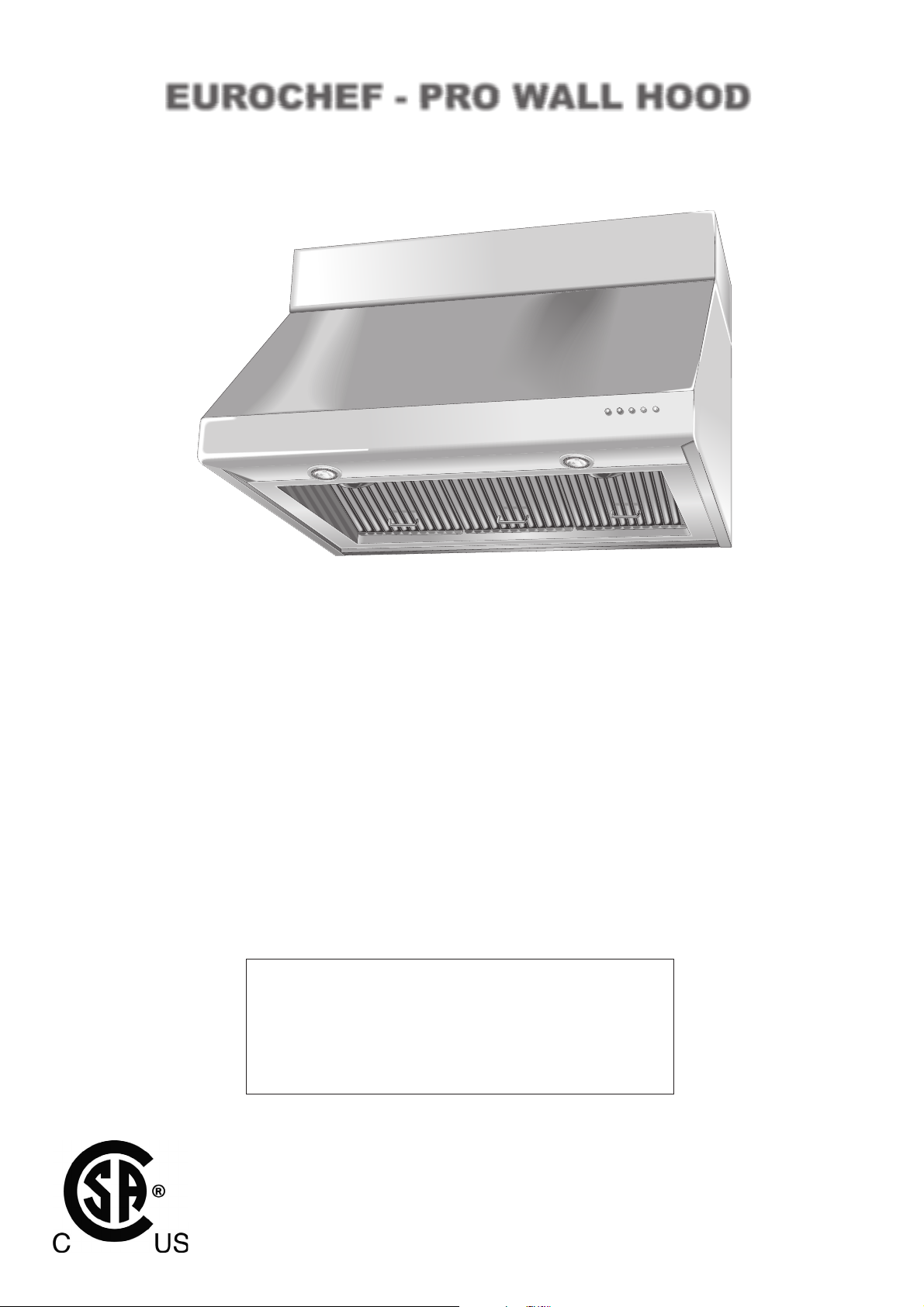
EUROCHEF - PRO WALL HOOD
INSTALLATION INSTRUCTIONS
TIMER
3
2
1
Shown with accessory Duct Cover Kit and accessory Warming Lamp Kit
APPROVED FOR ALL RESIDENTIAL APPLIANCES
FOR RESIDENTIAL USE ONLY
PLEASE READ ENTIRE INSTRUCTIONS BEFORE PROCEEDING.
INSTALLATION MUST COMPLY WITH ALL LOCAL CODES.
IMPORTANT: Save these Instructions for the Local Electrical Inspector’s use.
INSTALLER: Leave these Instructions with this unit for the owner.
OWNER: Retain these instructions for future reference.
SAFETY WARNING
Turn off power circuit at service panel and lock out panel
before wiring this appliance.
REQUIREMENT: 120VAC, 60 Hz. 20A Branch Circuit
Air-2
READ AND SAVE THESE INSTRUCTIONS
EUROCHEF U.S.A.
41 MERCEDES WAY SUITE 25 EDGEWOOD NEW YORK 11717 – TEL. 866-844-6566
WWW.DELONGHIMAJORAPPLIANCES.COM
WWW.DELONGHI RANGES.COM
1
Page 2
EUROCHEF - PRO WALL HOOD
HOODS WEIGHT MODEL NUMBER
24” range hood with 600 CFM blower 22 lbs EC PH24S
30” range hood with 600 CFM blower 30 lbs EC PH30S
36” range hood with 600 CFM blower 36 lbs EC PH36S
48” range hood with 1200 CFM blower 48 lbs EC PH48S
FEATURES
Controls: 4-speed electronic with 15” minute delayed shutoff
timer
Fabrication: Welded, polished and brushed seams
All edges hemmed
Features: 304 stainless hood baffle filter and grease tray
12V halogen lighting, lamps included
Top and Back ducting 24”, 30”, 36” hoods
Transition to 8” round with damper included
Install to wall or cabinets
ACCESSORIES MODEL NUMBER
WARMING LAMP KIT
Includes 175W Warming Lamps, rocker switches, quick connect wiring. Field installable.
24”/30” Warming Lamps Kit: (1) 175W Warming Lamp EC LAMP24/30
36” Warming Lamps Kit: (2) 175W Warming Lamp EC LAMP36
48” Warming Lamps Kit: (2) 175W Warming Lamp EC LAMP48
BACKSPLASH WITH WARMING SHELVES KIT
Includes telescoping 2-piece backsplash, removable & dishwasher safe shelves
24” Backsplash with (1) shelf EC BKSPL24
30” Backsplash with (1) shelf EC BKSPL30
36” Backsplash with (2) shelf EC BKSPL36
48” Backsplash with (2) shelf EC BKSPL48
RECIRCULATING KIT
Includes 4” high duct cover, 90 degree transition, charcoal filters
NOTE: Do not use with indoor BBQ. Do not use with Blower Upgrade Kit (below).
24” Recirculating Kit EC DLK24
30” Recirculating Kit EC DLK30
36” Recirculating Kit EC DLK36
Not Available for 48” Hoods
REPLACEMENT CHARCOAL FILTER
For use with Recirculating Kit Only Includes 2 Sets of Filters EC FILT
BLOWER UPGRADE KIT
Kit for 30” and 36” hoods only. Includes 600 CFM blower.
Not for use with Recirculating Kit or horizontal ducting EC BLMT
DUCT COVER 6”
Stackable 304 stainless steel.
24” wide 6” high duct cover EC CVR246W
30” wide 6” high duct cover EC CVR306W
36” wide 6” high duct cover EC CVR366W
48” wide 6” high duct cover EC CVR486W
DUCT COVER 12”
Stackable 304 stainless steel.
24” wide 12” high duct cover EC CVR2412W
30” wide 12” high duct cover EC CVR3012W
36” wide 12” high duct cover EC CVR3612W
48” wide 12” high duct cover EC CVR4812W
2
Air-2
Page 3
EUROCHEF - PRO WALL HOOD
READ THESE INSTRUCTIONS COMPLETELY AND CAREFULLY
WARNING
TO REDUCE THE RISK OF FIRE, ELECTRICAL SHOCK
OR INJURY TO PERSONS, OBSERVE THE FOLLOWING:
A. Use this unit only in the manner intended by the manufac-
turer. If you have any questions, contact the manufacturer.
B. Before servicing or cleaning unit, switch power off at the
service panel and lock service panel to prevent power
from being switched on accidentally. If the service panel
cannot be locked, fasten a tag or prominent warning label to the panel.
• For general ventilating use only. Do not use to exhaust
hazardous or explosive materials or vapors.
• Structural framing, installation work and electrical wiring must
be done by qualified person(s). In accordance with all applicable codes and standards including tire-rated construction.
• Sufficient air is needed for proper combustion and exhausting of gases through the flue (chimney) of fuel burning equipment to prevent back drafting. Follow the heating equipment manufacturer’s guideline and safety standards such as those published by the National Fire Protection Association (NFPA), and the American Society
for Heating, Refrigeration and Air Conditioning Engineers
(ASHRAE), and the local code authorities.
• Local codes vary. Installation electrical connections and
grounding must comply with applicable codes. In the
absence of local codes, the vent should he in-stalled in
accordance with National Electrical Code ANSI/NFPA 701990 or latest edition.
ADVERTISSEMENT
POUR RÉDUIRE LE RISQUE D’INCENDIE, DE CHOC
ÉLECTRIQUE OU DE BLESSURES, IL FAUT OBSERVER
LES REGLES SUIVANTES:
A. Utiliser cet appareil uniquement de la maniére prévue par le
fabricant. En cas de question, consulter le fabricant.
B. Avant toute intervention ou nettoyage, couper l’alimentation
électrique au disjoncteur et verrouiller le panneau du disjoncteur
pour éviter la mise sous tension accidentelle. S’il n’est pas
possible de verrouiller le panneau du disconcteur, attacher un
placard ou une étiquette trés visible au panneau.
• For general ventilating use only. Do not use to exhaust hazardous or explosive materials or vapors.
• Structural framing, installation work and electrical wiring must
be done by qualified person(s). In accordance with all applicable codes and standards including tire-rated construction.
• Sufficient air is needed for proper combustion and exhausting
of gases through the flue (chimney) of fuel burning equipment
to prevent back drafting. Follow the heating equipment
manufacturer’s guideline and safety standards such as those
published by the National Fire Protection Association (NFPA),
and the American Society for Heating, Refrigeration and Air
Conditioning Engineers (ASHRAE), and the local code authorities.
• Local codes vary. Installation electrical connections and grounding must comply with applicable codes. In the absence of
local codes, the vent should he in-stalled in accordance with
National Electrical Code ANSI/NFPA 70-1990 or latest edition.
CONSIDERATIONS BEFORE
INSTALLING HOOD
1. For the most efficient air flow exhaust, use a straight run or as few
elbows as possible.
2. Do not use flex ducting use metal ductwork only to reduce the risk
of fire.
3. COLD WEATHER installations should have an additional backdraft
damper installed to minimize backward cold air flow and a nonmetallic thermal break to minimize conduction of outside temperatures as part of the ductwork. The damper should be on the cold air
side of the thermal break. The break should be as close as possible to where the ducting enters the heated portion of the house.
4. Hood installation height above cooktop is the users preference.
The lower the hood above the cooktop, the more efficient the capturing of cooking odors, grease, and smoke. This hood has been
approved for installations as low as 24 inches* above the cooktop.
The lower height may be inconvenient for tall people and large
cooking vessels. Consequently, The manufacturer recommends
the hood be installed 30-to-36 inches above the countertop.
* For indoor grill installations, The manufacturer recommends a mini-
mum of 30" clearance.
5. Make-Up Air: Local building codes may require the use of makeup air systems when using ducted ventilation systems greater
than specified CFM of air movement. The specified CFM varies
from locale to locale. Consult your HVAC professional for specific
requirements in your area.
6. Skill Level - Installation of this vent hood requires basic mechani-
cal and electrical skills.
7. Completion time- 1 to 3 hours.
8. Proper installation is the responsibility of the installer.
9. Product failure due to improper installation is not covered under the
Warranty.
CAUTION:
To reduce risk of fire and to properly exhaust air, be sure to duct
air outside - Do not vent exhaust air into spaces within walls or
ceilings or into attics, crawl spaces, or garages.
PRUDENCE:
Il faut prendre soin d’installer tul conduit vers l’extérieur pour
réduire le risque d’incendie et pouvoir évacuer l’air correctement.
Il ne faut pas évacuer l’air correctement. Il ne faut pas évacuer
l’air dans l’espace entre les parois d’un mur, un plafond ou un
grenier, un espace sanitaire ou ou garage.
WARNING:
Any such alteration from original factory wiring could result in
damage to the unit and/or create an electrical safety hazard.
ADVERTISSEMENT
Toute modification de ce type du branchement d’usine pente
endommager l’appareil ou créer un risque de choc électrique.
Air-2
3
Page 4
EUROCHEF - PRO WALL HOOD
TIMER
CONTENTS AND PAGE NUMBER
Product Dimensions....................................................... pg.4
Advance Planning...........................................................pg.5
Using Duct Cover Accessories........................................ pg.5
Tools and Materials Required ......................................... pg.5
Remove the packaging................................................... pg.6
Parts Provided............................................................... pg.6
Step 1: Determine Ductwork and Wiring Locations............ pg.7
Step 2: Prepare hood for installation................................. pg.7
Step 3A: Install Hood Onto Wall...................................... pg.10
Step 3B: Install Hood Beneath Sofit or cabinet................. pg.11
Step 4: Connect Ductwork ............................................ pg.12
Step 5: Connect Electrical ............................................ pg.12
Step 6: Install Duct Covers ........................................... pg.12
Step 7: Tighten hanging screws .................................... pg.13
Step 8: Re-Install the Filter Frame ................................. pg.13
Step 9: Install Grease filter trays + filters ........................ pg.14
Step 10: Test hood ...................................................... pg.14
Care and use instructions ............................................ pg.15
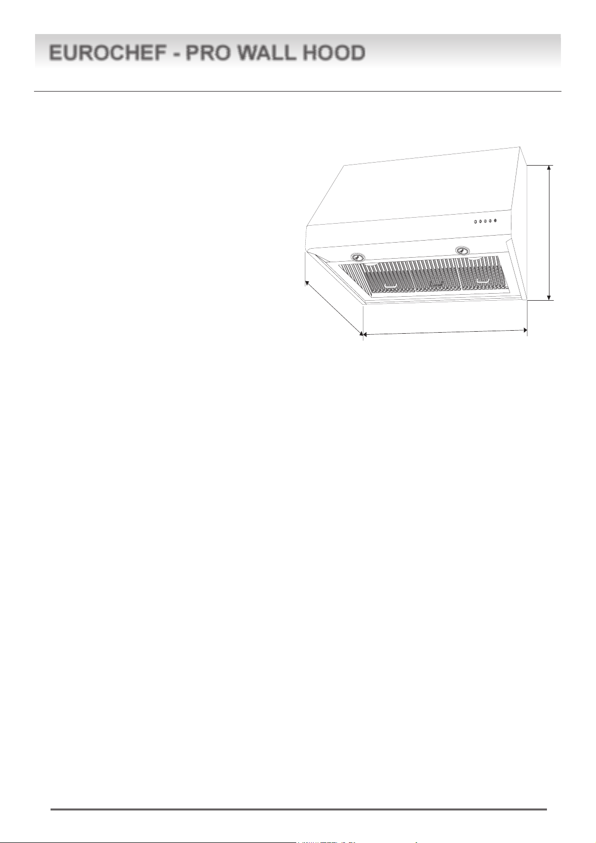
24”
PRODUCT DIMENSIONS
TIMER
3
2
1
24”- 30”- 36”- 48”
18”
4
Air-2
Page 5
EUROCHEF - PRO WALL HOOD
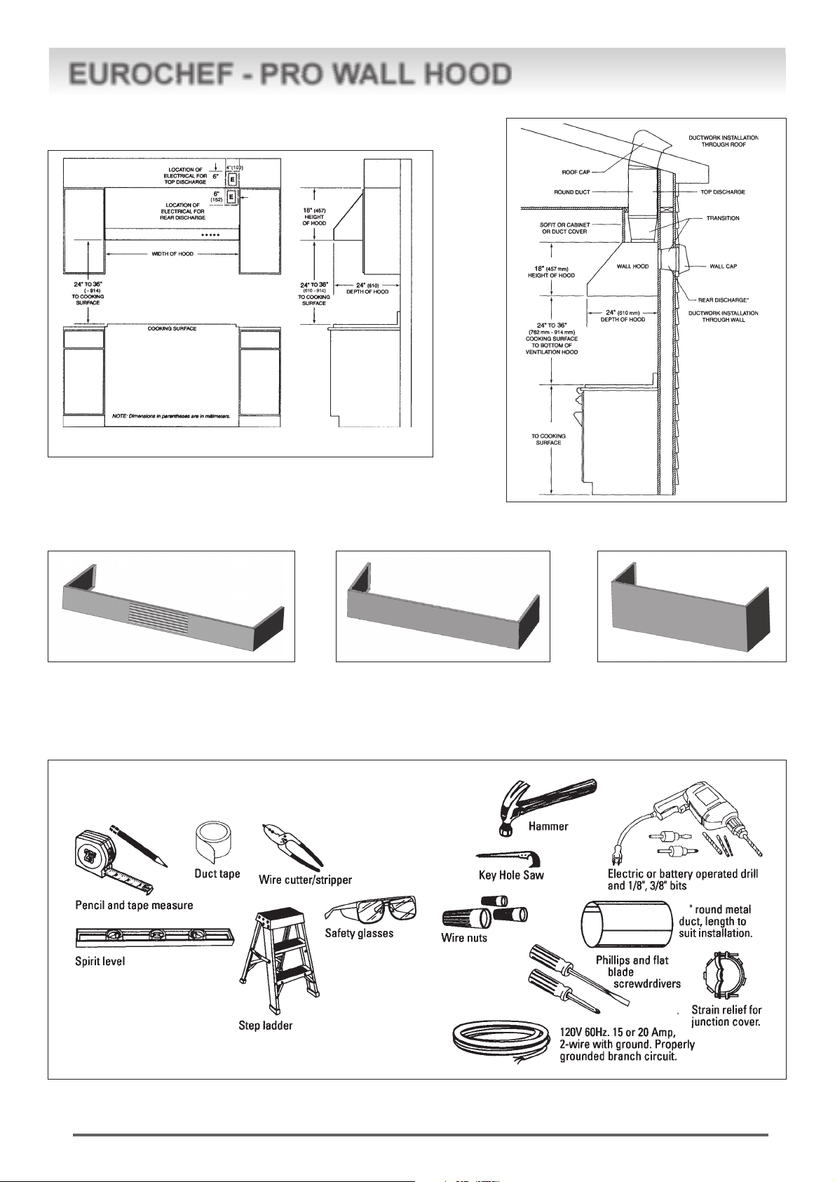
ADVANCE PLANNING
Cabinetry and electrical placement for 24-inch deep wall hoods.
USING DUCT COVER ACCESSORIES
To avoid gaps, plan the hood installation height for duct cover use.
36” (914 mm)
lnstallatian
dimensions
for 24 deep
wall hoods.
Recirculating Kit Cover 4” (if used) Duct cover 6” Duct cover 12”
1. Duct covers and Recirculating Kit covers are stackable.
2. The hood is 18” tall and can be installed from 24” to 36” above cooking surface (30” to 36” is optimum).
3. Locate hood so that duct covers and Recirculating Kit Cover (If used) leave no gap between hood and ceiling.
TOOLS AND MATERIALS REQUIRED (NOT SUPPLIED)
8
Air-2
5
Page 6

EUROCHEF - PRO WALL HOOD
REMOVE THE RANGEHOOD
DO NOT GRAB BODY HERE
GRAB BODY
HERE
LOCATION OF
COMPONENTS
PARTS PROVIDED
Locate the parts packed with the hood.
Duct
Transition
GRAB BODY
HERE
Washers
no. 4 for 24”-30”
no. 6 for 36”-48”
for use with screws
to attach hood to
Bracket
Parts Included with your Hood
• Hood with blower installed
• 12-Volt halogen bulbs, installed
• Care & Use /Installation Instructions
• Registration Card
• Filters (24” & 30” = 2; 36” = 3; 48” = 4)
• Grease trap (24” & 30” = 2; 36” = 3; 48” = 4)
• Transition with Back draft damper
• Fasteners
• Wooden bracket for Hood Support
Parts Not Included with your Hood
• Duct Cover Kit, 6" or 12" height
• Warming lamp kit
• Back Splash + Warming shelf kit
• Blower upgrade kit for 30” - 36” models only
• Recirculating kit
• See your dealer to purchase these kits
Screws to hang and
secure hood to the
Wood Bracket
(torx 20)
4,5 x 20 mm
no. 4 for 24”-30”
no. 6 for 36”-48”
Grease Trays
(2 with 24”, 30” models)
(3 with 36” models)
(4 with 48” models)
Stainless Steel Grease Filters
(2 with 24”, 30” models)
(3 with 36” models)
(4 with 48” models)
Washers
no. 3 6 x 24
for use with
screws to
anchor hood
no.3 screws and no.3 wall anchors
(Philips) M5 x 57 mm
no. 4 screws 80mm to attach wood
bracket to wall studs (torx 25)
HARDWARE PACKAGE
Locate and check contents.
Screws shown actual size
no. 4 screws to fix duct transition (torx 20)
Wood bracket
6
3,9 x 9,5 mm
Air-2
Page 7

EUROCHEF - PRO WALL HOOD
STEP 1 DETERMINE HOOD, DUCTWORK
AND WIRING LOCATIONS
• Use a level to draw the cooktop centerline vertically up the
wall to the ceiling.
• Measure desired distance from the bottom of the hood to
the cooking surface, 24" min. to 36" max.
Note: If installing with Duct Cover Kit or Recirculating Kit, see
“Using Duct Cover Accessories”, pg 5 to eliminate gaps at ceiling.
• Use a level to draw a straight horizontal pencil line
indicating the bottom of the hood.
FOR VERTICAL (Straight Up) DUCTING:
• Affix enclosed paper template to wall.
• If venting out the ceiling, extend the centerline forward on
the ceiling or soffit.
• Locate the centerline of a 8-1/2" diameter hole on the ceiling
or soffit by measuring 6" from the wall.
FOR DUCTING THROUGH WALL PLEASE SEE
TEMPLATE:
Use template to identify wall exit hole location, wood wall bracket
location, and wiring location.
REMOVE FILTER FRAME
- Remove Filter Frame per photographs
- Store Filter Frame in safe place so it will not be damaged.
- Do not loose the Filter Frame screws, re-screw them loosely,
back into the hood.
OTHER PREPARATIONS
• Move blower to back if necessary.
• Install transition to top or back.
• If using Recirculating Kit, affix 90° transition from kit. Must
install the hood to the wall. (step 3A)
• If using Warming Lamps Kit: install kit now or later.
• If using Blower Upgrade Kit ( 30”-36” only): install kit now or
later.
• Move junction box from top to back if preferred.
• Install strain relief in junction box
JUNCTION BOX LOCATION:
• The junction box is fastened to the top of the hood. Relocate
to back if preferred.
• Remove junction box cover and one knockout.
Install strain relief.
STEP 2 PREPARE HOOD FOR
INSTALLATION
Install Transition Onto Top or Back of Hood
IMPORTANT:
Remove shipping tape
from damper and
check that damper
moves freely.
• Place the transition piece over the hood exhaust and secure
with 4 screws provided.
• Use duct tape to seal the connection. Check to be sure the
damper moves freely.
Top of Hood
Duct Transition
Air-2
7
Page 8

EUROCHEF - PRO WALL HOOD
BLOWER POSITION CHART
Hood size Motor Recirculating Kit option Top ducting option Rear ducting option
24 ” 1 YES YES YES
30 ” 1 YES YES YES
30 ” 2* NO YES NO
36 ” 1 YES YES YES
36 ” 2* NO YES NO
48” 2 NO YES NO
(*) with Blower Upgrade Kit
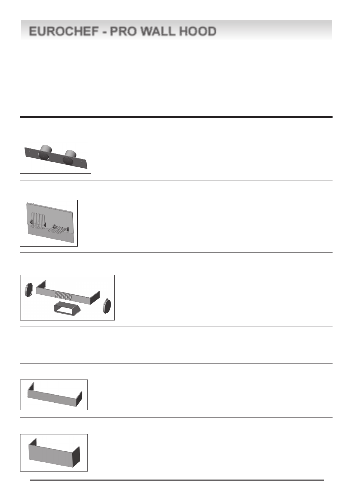
BLOWER POSITION OPTION
model 24
Vertical Discharge
model 24
Horizontal Discharge
model 30 36
Vertical Discharge
model 30 36
Horizontal Discharge
model 30 36
model 48
two blowers Vertical
Discharge
(with Blower
Upgrade Kit)
model 30 36
model 48
two blowers
Horizontal Discharge
(2 Blower may Not
Duct out Rear)
8
Air-2
Page 9

EUROCHEF - PRO WALL HOOD
IF CHANGING BLOWER POSITION
1. Disconnect motor from power supply
2. Remove Blower security screw from blower bracket and
remove blower.
3. Loosen 4 screws from blower bracket.
4. Shift blower to right and Remove Blower.
5. Loosen 4 screws and remove sealing plate covering back
venting hole.
6. Reverse this procedure in new locations.
7. Reconnect blower to power supply.
SECURITY SCREW
BLOWER UPGRADE KIT 30” AND 36” HOODS
A
“A”: remove bracket knock out
before fixing 2nd motor
1. Follow steps 1, 2, 3, 4 above.
2. Remove blower from bracket
3. Remove knockout from blower bracket
4. Re-attach blower and blower upgrade kit with screws
provided.
5. Re-attach blower to top of hood only. Double Blowers may
not be installed on back of hood.
6. Tighten 4 screws, and screw in one security screw.
7. Each Blower must be connected to the hood power supply.
WARNING:
• disconnect the motor before changing position; reconnect
after it is moved.
ATTENTION:
Débrancher le moteur avant de changer de position, rebrancher
après le changement de position
Air-2
9
Page 10

EUROCHEF - PRO WALL HOOD
TIMER
STEP 3A: INSTALL HOOD ONTO WALL (see enclosed template)
SKIP THIS STEP IF INSTALLING BENEATH A SOFFIT OR CABINET, GO TO STEP 3B.
• Affix enclosed paper template to wall.
• From the line indicating the bottom of the hood, measure
17” up and draw another line for the location of the Wood
Bracket. See illustration.
• Locate at least 2 vertical studs at the Wood Bracket.
• Center the supplied Wood Bracket, left to right and below
the marked line.
• Secure the Wood Bracket to 2 or more vertical studs, using
at least 2 of the 4 supplied long screws.
• Insert hood mounting screws in the Wood Bracket at the
locations shown in the diagram, so screws protrudes 1/4".
This 1/4” gap will provide clearance to hang the hood.
IMPORTANT: FRAMING MUST BE CAPABLE OF
SUPPORTING UP TO 150 LBS
Hang Hood On Wood Bracket
• Lift the hood and hold close to the installation location. Route
house wiring through the knockout and into the junction box.
• Place the hood over the Wood Bracket. Be sure the mount-
ing screws engage the keyhole slots in the back of the hood.
• Check to be sure the hood is level and centered.
• Use midpoint arrow in back of hood to confirm horizontal
position.
2
T
I
M
E
3
R
1
24
Centerline of
Installation Space
IMPORTANT: Screws must penetrate at least 1-1/2" into vertical studs. Countersink screws into support.
AFFIXING THE HOOD MOUNTING SCREWS
x
24”
8”
30”
36”
48”
11”
14”
20”
5/16”
1
x
x
Original Mounting
Screws as Shipped
2”
Test Duct Cover Fit (do not install Duct covers)
• Place duct covers or recirculating cover over the top of the
hood to check for gaps.
• Confirm that the ceiling gap, if any, is less then 3/8”.
• If gap is greater than 3/8", OR if duct covers do not fit, it is
necessary to remove, re-measure and reinstall the Wood
Bracket.
10
Air-2
Page 11

EUROCHEF - PRO WALL HOOD
STEP 3B: ALTERNATE MOUNTING
METHOD
INSTALL HOOD TO SOFFIT OR BENEATH CABINETS
SKIP THIS STEP IF USING WALL MOUNTING METHOD
When necessary, the hood may be installed so that it is
supported by the soffit.
• The soffit should be constructed with 2 x 4’s.
• Determine the installation location on the wall.
• Continue the centerline forward on the bottom of the cabinet
or soffit.
• If ducting vertically the opening above the hood should allow
for the 8" round duct and clearance to slide the hood back
against the wall. Requires 8" Min. Opening For Ductwork
and Hood Installation
Requires 8” Min. Opening
For Ductwork and Hood
Installation
• Affix enclosed paper template to wall
IMPORTANT: FRAMING MUST BE CAPABLE OF
SUPPORTING UP TO 150 LBS
Mount Hood onto Soffit or Cabinet
Note: If mounting to the underside of a cabinet with a recessed
bottom, install shims to fill the gap.
• The 2 x 4 studs must be located as shown in the chart, Dim.
A. to accept mounting screws.
“A”
Centerline to Stud
and Keyhole Slots
PRO HOOD 24” 11 - 9/16”
PRO HOOD 30” 14 - 9/16”
PRO HOOD 36” 17 - 9/16”
PRO HOOD 48” 23 - 9/16”
C
L
• Drive mounting screws into the studs until they protrude
1/4". The 1/4" gap will provide clearance to engage the keyhole slots in the top of the hood.
• Lift hood to installation position. Locate house wiring and
route through the knockout (from the back or top of the hood).
• Lift hood onto mounting screws. Slide back against the rear
wall.
• Tighten mounting screws.
• Add (2) security screws in top left and top right side of hood.
IMPORTANT: For additional support and to minimize
vibration during operation, the hood must be secured
to the back wall. Use wall anchors to fasten bottom
back of hood to the wall.
9” 3/4
½
3”
A
Top of hood
• Drill 1/8" pilot holes into the studs at the locations shown in
the top view illustration.
Air-2
11
Page 12

EUROCHEF - PRO WALL HOOD
STEP 4: CONNECT DUCTWORK
• Install ductwork.
• Secure joints in ductwork and transition with sheetmetal
screws and duct tape for an airtight seal.
• ATTENTION: Be sure that screws do not hamper the
dampers movement.
STEP 5: CONNECT ELECTRICAL
• Use wire nuts to connect incoming ground, neutral and hot.
• Push wires into junction box and replace cover. Be sure
wires are not pinched.
STEP 6: INSTALL DUCT COVERS
Verify that power is turned off at the source.
WARNING
If house wiring is not 2-wire with a ground wire, a ground must
be provided by the installer. When house wiring is aluminum, be
sure to use U.L. approved anti-oxidant compound and aluminum-to-copper connectors.
ATTENTION
Sí le câblage de la maison n’est pas du type a deux fils avec un
fil de terre, l’installateur doit fournir un circuit de terre. Quand
les fils de la maison sont en aluminium, il prendre soin d’utiliser
de la pâte antioxidation approuvée par UL et des connecteurs
pour l’aluminium-cuivre.
GREEN = GROUND
BLACK & BROWN = HOT
BLUE & WHITE = NEUTRAL
ASSEMBLY AND INSTALLATION
OF THE DUCT COVERS &
RECIRCULATING KIT COVER
Optional duct covers shown in advance planning section may
be used to fill the space between the hood and ceiling in wall
mount installations. 6" and 12" high duct covers are available
and may be ordered separately.
1. If multiple duct covers are used, connect the pieces together
using sheetmetal screws provided with duct covers.
Remove plastic film.
2. Attach the duct cover(s) to the hood using screws provided.
3. From inside of hood, insert screws supplied (3,5 x 9,5) through
holes in front and side of hood into covers.
12
Air-2
Page 13

EUROCHEF - PRO WALL HOOD
STEP 7: TIGHTEN - HANGING SCREWS
• With Filter Frame still removed from Step 2
• Adjust hood up to eliminate any gaps at ceiling. Tighten
hanging screws.
• Add (2) more security screws + Washers at wood bracket.
• IMPORTANT: If Installing optional Backsplash Kit install this
kit BEFORE installing wall anchors
(see instruction with kit)
Install Bottom Wall Anchors
• Drill 1//8" pilot holes into the two lower mounting holes. Enlarge
the holes if they did not enter studs to 3/8".
• Install (2) or (3) wall anchors at bottom of hood.
• Remove anchor screws and add a flat washer provided. Drive
screws into anchors and tighten.
• If a Wood Stud was discovered at wall anchor locations use
80mm Wood Screw supplied with Washer (instead of Wall
anchor). Drive screws and tighten.
STEP 8: RE-INSTALL THE FILTER FRAME
• Use screws removed in Step 2 to re-install Filter Frame, per
photograph.
Air-2
13
Page 14

EUROCHEF - PRO WALL HOOD
STEP 9: INSTALL FILTER
• Place filter drip trays into the bottom rear of the hood.
• Insert top of grease filter first, than rotate bottom filter and drop
into grease tray.
• To remove the filters, grasp the handle, push the filter up and
lift out.
STEP 10: TEST FUNCTION OF HOOD
- Blower
- Light
14
Air-2
Page 15

EUROCHEF - PRO WALL HOOD
CARE AND USE
REPLACING HALOGEN BULB
ROTATE
OPERATION
Press any speed to turn hood on. Press same button to turn
hood off. Active speed is shown by a button back light.
CONTROL:
1. 1 Speed
2. 2 Speed
3. 3 Speed
4. 4 Speed
Light
• After waiting for lamp to be cool, twist off lamp bezel as shown,
and pull out bulb.
• Replace bulb with 20W G4 base halogen bulb purchased at
your local hardware store.
• Follow instructions on the bulb. Do not touch the bulb with
your bare fingers.
• Reinstall lamp bezel
CLEANING FILTERS
Clean grease trays and baffle filters regularly, at least once every
3 months.
Filters and tray are dishwasher safe.
CLEANING HOOD
Do not use abrasive products
Wipe the outside of stainless steel with sudsy water or
household cleaners such as Fantastic or Formula 409. Rinse
well and dry with soft cloth.
DELAYED SHUTOFF
By pressing down on any speed key for 2 seconds, while hood is
running the 15 minute Delayed Shutoff mode will start indicated
by flashing backlight. After 15 minutes the hood will shutoff.
WARRANTY:
Eurochef USA warrants the USA Pro Hood against defects in
materials or workmanship for 1 year from date of purchase.
EUROCHEF U.S.A.
41 MERCEDES WAY SUITE 25
EDGEWOOD, NEW YORK 11717
TEL. 866-844-6566
WWW.DELONGHIMAJORAPPLIANCES.COM
WWW.DELONGHI RANGES.COM
Air-2
15
Page 16

EUROCHEF - PRO WALL HOOD
16
EUROCHEF U.S.A.
41 MERCEDES WAY SUITE 25 EDGEWOOD NEW YORK 11717 – TEL. 866-844-6566
WWW.DELONGHIMAJORAPPLIANCES.COM
WWW.DELONGHI RANGES.COM
Air-2
 Loading...