

Page 1
INSTRUCTION ON MOUNTING AND USE S72 -
Page 2
Ø 150mm
M
B
E
E
P
the height of the fascia panel is 6.8cm
Ø 150mm
LR
D
1 2
E
87
min.
135
D
3
Page 3

F
G
H
C
Q
4 5
6 7
Page 4

5
2
Fig. 8
8
6
3
9
Fig. 9
4
7
1
8
4
Fig. 11
11
10 12
Fig. 10
Fig. 12
Page 5

GB
Consult the designs in the front pages referenced in the text
by alphabet letters. Closely follow the instructions set
out in this manual. All responsibility, for any eventual
inconveniences, damages or fires caused by not complying
with the instructions in this manual, is declined.
Installation
The cooker hood must be placed at a minimum distance of
60 cm from the cooking plane for electric cookers and 70 cm
for gas or mixed cookers.
If the instructions for installation for the gas hob specify a
greater distance, this must be adhered to.
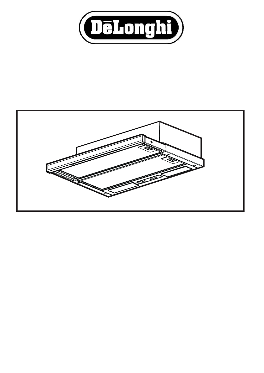
The hood is equipped with a top air outlet B (Fig. 2) for
discharge of fumes to the outside (Ducting version –
exhaust pipe and pipe fixing clamps not provided).
Should it not be possible to discharge cooking fumes and
vapour to the outside, the hood can be used in the filter
version, fitting an activated carbon filter (in the case of the
model with two suction motors then two active carbon filters
are required), a discharge tube, for the expulsion of fumes,
should be mounted on the connection ring C (Fig. 5) situated
on the top of the wall cabinet (discharge tube and fixing
brackets are not supplied).
The models with no suction motor only operate in ducting
mode, and must be connected to an external suction device
(not supplied).
Preliminary information for installation of the hood:
During the installation phase do not connect the hood to the
power supply.
Attention! The 2 fixing brackets are lodged in the protection
in polyester packing
The brackets are one right R and one left L (see bossing
shown on the brackets).
1. Fix the D bracket (Fig.1) to the side panel of the wall unit
2. If not already mounted, fix the two E brackets (Fig.2) to
3. Affix the spacer M with three Clips from the external part
4. Insert the cooker hood in the wall cabinet, ensuring to
INSTRUCTION ON MOUNTING AND USE
with two screws for every bracket (the right R bracket
on the right side and the left L bracket on the left side).
Align the bracket with the lower border.
Position the bracket to touch the back border of the wall
cabinet, considering that the back border of the bracket
corresponds to the back side of the cooker hood;
If the cooker hood is provided with a spacer, in case of
use, move the bracket forward to the same thickness
as the spacer.
Drill a hole on the ceiling of the wall cabinet to pass the
discharge tube and the electrical cable (the quote
indicated in Fig. 1 does not include the eventual spacer).
the sides of the hood (one per side).
a. remove the extractable part of the cooker hood;
b. remove the grease filter/s;
c. fix the brackets with two screws P per bracket from
inside the cooker hood, affix them as more as possible
upwards (air exit side) and then serrate the screws.
of the cooker hood (if supplied - Fig. 2).
position the cooker hood bracket E above the wall
cabinet bracket D (Fig. 3).
Thread the electric cable through the appropriate
perforation.
5. Block the cooker hood with two screws on the frontal part
(Fig. 3 – one per side).
6. Connect the cable to the electrical mains, only when the
installation is completed.
7. If the cooker hood should not touch perfectly with the
lower border of the wall cabinet then regulate by
loosening the screws P of the brackets E mounted on
the cooker hood (Fig. 2), it will be possible to regulate
the perfect matching of the cooker hood and wall cabinet,
once regulated tighten the screws.
8. Regulate the gliding of the extractable drawer in relation
to the depth of the wall cabinet by acting on the two skirting
boards F (Fig. 4).
In this way it will be possible to place the front in line with
the wall cabinet (Fig. 4).
a. Loosen the screws on the skirting board F;
b. Move the ledges backwards or forwards depending
on requirement.
c. Lock in the screws on the ledges.
9. Install a discharge tube on the connection ring C supplied,
preferably with a diameter equivalent to the connection
ring (Fig. 5). the discharge tube should be sufficiently
long to reach outside (Suction version) or the ceiling of
the wall cabinet (Filter version).
10. Fix the connection ring C (snap into place), at the upper
exit of the cooker hood.
To ease the installation, the ring is equipped with an index
G that should correspond to the appropriate guide H
placed on the upper air exit.
11. Complete the installation of the discharge tube.
12. Open the extractable drawer (Fig.6) and apply the
aesthetic Q mask (if supplied) with two screws from the
inside of the hood (Fig, 7).
13. Re-install the grease filters, connect the cooker hood to
the electrical mains and check the perfect operation.
Electrical connection
The electrical tension must correspond to the tension noted
on the label placed inside the cooker hood. Connect the
electrical plug, where provided, to the an easily accessible
outlet in conformity with local standards in force.
Where an electrical plug is not provided (for direct connection
to electrical network) place a standards approved bipolar
switch with an aperture distance of not less than 3mm
(accessible) from the contacts.
Description of the hood - Fig. 8
1 Control panel
2 Grease filter (1 or 2 depending on the model in possession)
3 Grease filter release handle
4 Lighting
5 Vapour screen (extractable), according to the model
available, which may be in metal, glass or provided with
grease filter.
6 Aesthetic mask (Available on the basis of the model in
possession).
7 Spacer (Available on the basis of the model in possession).
8 Wall cabinet (not supplied, the cabinet illustration is
included to explain the type of installation).
Page 6

GB
Operation
Description of control panel and hood operation
INSTRUCTION ON MOUNTING AND USE
ab
a. on/off light switch
b. on/off aspiration switch and power selection
Use the high suction speed in cases of concentrated kitchen
vapours. It is recommended that the cooker hood suction
is switched on for 5 minutes prior to cooking and to leave
in operation during cooking and for another 15 minutes
approximately after terminating cooking.
Cleaning
The cooker hood should be cleaned regularly internally
and externally.
For cleaning use a cloth moistened with denatured alcohol
or neutral liquid detergents. Avoid abrasive detergents.
Failure to carry out the basic standards of the cleaning of the
cooker hood and replacement of the filters may cause fire
risks.
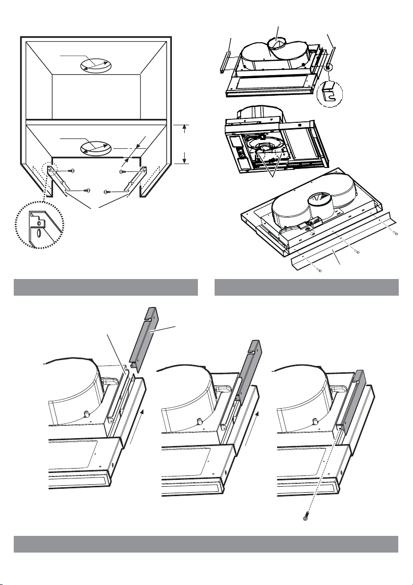
Cleaning the glass vapour screen (available only in
some models)
The glass be dismounted and cleaned using a normal glass
detergent.
Instructions for removing the glass (Fig. 12):
1. Remove the grease filter.
2. Lightly push the glass downwards and allow it slide
forwards.
3. Remove the glass allowing it to rotate slightly.
After cleaning, follow the instructions in reverse to remount
the glass.
Maintenance
Prior to any maintenance operation ensure that the cooker
hood is disconnected from the power supply.
The carbon filter may NOT be washed or regenerated.
Place the carbon filter in order to cover the protection grill for
the motor fan wheel, then turn the central handle P of the filter
clockwise (Fig. 10).
To dismount the central handle P of the filter turn the handle
anti-clockwise.
Replacing lamps - Fig. 11
Firstly check that the lamps are well cooled prior to replacing
them.
Access the lamp housing area:
remove the lamp holder using a small screwdriver or similar
tool as a lever.
Replace the damaged light bulb.
Use only 40W max (E14) olive shape light bulbs.
Then close the lamp housing (snap lock).
If the lights do not work, make sure that the lamps are
fitted properly into their housings before you call for
technical assistance.
Caution
This appliance is designed to be operated by adults. Children
should not be allowed to tamper with the controls or play with
the appliance.
Do not use the cooker hood where the grill is not correctly
fixed! The suctioned air must not be conveyed in the same
channel used for fumes discharged by appliances powered
by other than electricity. The environment must always be
adequately aerated when the cooker hood and other
appliances powered by other than electricity are used at the
same time. Flambé cooking with a cooker hood is
prohibited. The use of a free flame is damaging to the filters
and may cause fire accidents, therefore free flame cooking
must be avoided. Frying of foods must be kept under close
control in order to avoid overheated oil catching fire. Carry
out fumes discharging in accordance with the regulations in
force by local laws for safety and technical restrictions.
GB - This appliance is marked according to the European directive 2002/96/EC on
Waste Electrical and Electronic Equipment (WEEE). By ensuring this product is
disposed of correctly, you will help prevent potential negative consequences for the
environment and human health, which could otherwise be caused by inappropriate
waste handling of this product.
Grease filter
This must be cleaned once a month using non aggressive
detergents, either by hand or in the dish-washer, which must
be set to a low temperature and a short cycle.
When washed in a dish-washer, the grease filter may
discolour slightly, but this does not affect its filtering capacity.
To remove the grease filter, pull the spring release handle
(f) towards the opposite side of the cooker hood and extract
the filter - (Fig. 9).
Charcoal filter (filter version only)
It absorbs unpleasant odours caused by cooking.
Two carbon filters are required for cooker hoods with two
motors and one filter for cooker hoods with one motor.
The carbon filter should be replaced every 4 months in cases
of normal use, or more frequently for intensive use of the
cooker hood.
The symbol on the product, or on the documents accompanying the product,
indicates that this appliance may not be treated as household waste. Instead it
shall be handed over to the applicable collection point for the recycling of electrical
and electronic equipment. Disposal must be carried out in accordance with local
environmental regulations for waste disposal.
For more detailed information about treatment, recovery and recycling of this
product, please contact your local city office, your household waste disposal service
or the shop where you purchased the product.
 Loading...