

DeLonghi Bran 0011M H Installation, Operating & Service Instructions
INSTALLATION - OPERATING - SERVICE MANUAL
Air/water heat pumps, heating only, with
domestic hot water production, axial-flow
fans and water pump assembly.
GB
BRAN 0011M H
BRAN 0025M H
BRAN 0041M H
2
BRAN H GB 03/2009
User
Installer
Assistance
Important
Prohibition
Danger voltage
Danger high temperatures
The manufacturer reserves the right to modify the data in this manual without warning.
The following symbols are used in this publication and inside the unit:
U
I
A
INDEX
U I A
General warnings 3
Waiver of liability 3
Fundamental safety rules 3
Receiving and handling the product 4
Description of standard unit 5
Dimensioned drawings 6
Installation 6
Water connections 7
Water circuit data 9
Operating diagrams 10
Electrical connections 12
Mains power supply connections 13
Installer connections 14
Operating characteristics 16
General technical data 21
Checking and starting up the unit 23
HSW11 functions 24
LEDs and display 25
Displaying alarms 37
Shutting down for long periods 38
Routine maintenance 39
Special maintenance 39
Disposal 39
Troubleshooting 40
U I A AI
AI
A
A
A
AI
A
A
A
A
AI
UUI A
I A
I
I
I
A
A
I
I A
IIA
A
I A
I A
I A
3
GB 03/2009 BRAN H
INDEX
U I A
GENERAL WARNINGS
U I A
FUNDAMENTAL SAFETY RULES
U I A
These appliances have been designed to chill and/or
heat water and must be used in applications compatible
with their performance characteristics; these appliances
are designed for residential or similar applications.
Incorrect installation, regulation and maintenance or
improper use absolve the manufacturer from all liability,
whether contractual or otherwise, for damage to people,
animals or things.
Only those applications specifically indicated in this list
are permitted
Read this manual carefully. All work must be carried
out by qualified personnel in conformity with legislation in
force in the country concerned.
The warranty is void if the above instructions are not
respected and if the unit is started up for the first time
without the presence of personnel authorised by the
Company (where specified in the supply contract) who
should draw up a “start-up” report.
The documents supplied with the unit must be consigned to the owner who should keep them carefully for
future consultation in the event of maintenance or service.
All repair or maintenance work must be carried out by
the Company’s Technical Service or qualified personnel
following the instructions in this manual.
The air-conditioner must under no circumstances be
modified or tampered with as this may create situations
of risk. Failure to observe this condition absolves the
manufacturer of all liability for resulting damage.
When operating equipment involving the use of electricity and water, a number of fundamental safety rules must be observed,
namely:
The unit must not be used by children or by unfit persons without suitable supervision.
Do not touch the unit with bare feet or with wet or
damp parts of the body.
Never perform any cleaning operations before having
disconnected the unit from the mains power supply.
Do not modify safety or control devices without authorisation and instructions from the manufacturer.
Do not pull, detach or twist the electrical cables coming
from the unit, even when disconnected from the mains
electricity supply.
Do not open doors or panels providing access to the
internal parts of the unit without first ensuring that the
switch QF1 is in the OFF position (see the wiring diagram).
Do not introduce pointed objects through the air
intake and outlet grills.
Do not dispose of, abandon or leave within reach of
children packaging materials (cardboard, staples, plastic
bags, etc.) as they may represent a hazard.
Respect safety distances between the unit and other
equipment or structures. Guarantee adequate space for
access to the unit for maintenance and/or service operations.
Power supply: the cross section of the electrical cables
must be adequate for the power of the unit and the power supply voltage must correspond with the value indicated on the respective units. All units must be earthed in
conformity with legislation in force in the country concerned.
Terminals 6, 7, 8 & 9 may be live even after the unit is
disconnected. Make sure power is not connected before
proceeding.
Water connections should be carried out as indicated in
the instructions to guarantee correct operation of the
unit. Add glycol to the water circuit if the unit is not used
during the winter or the circuit is not emptied.
Handle the unit with the utmost care (see weight distribution table) to avoid damage..
WAIVER OF LIABILITY
This publication is the sole property of manufacturer. Any
reproduction or disclosure of such is strictly prohibited without the written authorisation of manufacturer.
This document has been prepared with maximum care and
attention paid to the content shown. Nonetheless, manufac-
turer waives all liability deriving from the use of such document.
Read this document carefully. All work must be performed,
components selected and materials used in complete accordance with the legislation in force in material in the country
concerned, and considering the operating conditions and
intended uses of the system, by qualified personnel.
U I A
When the items are consigned by the carrier, check that
the packaging and the unit are undamaged.
If damage or missing components are noted, indicate this on
the delivery note. A formal complaint should be sent via fax
or registered post to the After Sales Department within eight
days from the date of receipt of the items.
The units are supplied complete with:
- instruction manual;
- guarantee certificate;
- CE declaration;
- list of the main components and sub-assemblies fitted on
the product. These are contained in a plastic bag (A)
attached to the top of the chiller.
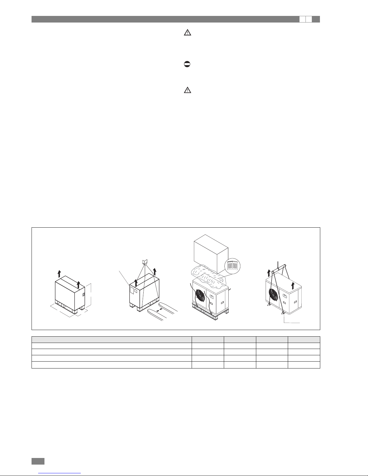
The unit must be handled by qualified and suitably equipped
personnel only using equipment appropriate for the weight
of the unit, in compliance with the safety standards in force
(and subsequent amendments.).
If a forklift truck is used, insert the forks under the base,
spacing the forks as wide apart as possible.
If a crane is used, pass the cables through the bottom of the
base, making sure they do not exert pressure on the unit.
Once the packaging has been removed, the appliance can
be lifted and moved by inserting two metal tubes (max.
diameter 22 mm) into the feet, and using suitable handling
equipment.
The instruction manual is an integral part of the unit
and should therefore be read and kept carefully..
The packaging should not be removed until the unit is
located in the installation site.
Do not dispose of packaging materials in the environment or leave them within reach of children as they may
represent a hazard.
The weight of the unit is biased towards the compressor side (side of the packaging with the bar code, see
the figure).
During transport, the unit should be kept in a vertical
position.
The unit must be stored sheltered from direct sunlight,
rain, wind or sand.
Avoid exposing the unit to direct sunlight, as the pressure inside the refrigerant circuit may reach dangerous
values and cause the activation of the safety valves,
where fitted.
Check the instructions on the packaging for stacking
units.
The packaging must be removed by the operator using
suitable protective equipment (gloves, glasses, etc.).
Take special care not to damage the unit.
Observe the local standards in force as regards disposal
of the packaging, using specialist collection or recycling
centres.
RECEIVING AND HANDLING THE PRODUCT
I A
4
BRAN H GB 03/2009
Hole Ø22
A
H
P
L
Bar code
(compressor side)
Dimensions 0011 0025 0041
Dimension L mm 950 950 950
Dimension P mm 450 450 450
Dimension H mm 650 950 1250
Gross weight kg 105 130 160
5
GB 03/2009 BRAN H
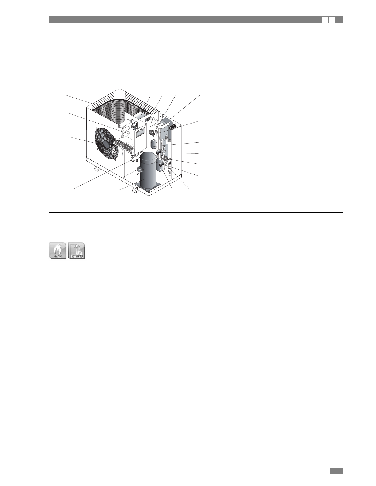
DESCRIPTION OF STANDARD UNIT
I A
These air/water heat pump with axial-flow fans operate with
R410A refrigerant fluid and are suitable for outdoor installation. The units are CE marked, as established by the EU
directives, including the latest amendments, and the corresponding approximated national legislation.
They are factory tested and on site installation is limited to
water and electrical connections.
VERSIONS AVAILABLE
BRAN H
Air/water heat pump, heating only, with domestic hot water production. Built-in water pump assembly complete
with electric heaters.
11
10
6
5
7
4
3219
12
8
14
15
9
13
1 Electric control board
2 Control panel
3 Heat exchanger user side
4 Low pressure gauge
5 High pressure gauge
6 Flow indicator
7 Scroll Compressor
8 Filter
9 Thermostatic valve
10 Axial-flow fan
11 Heat exchanger external side
12 Pump
13 Liquid receiver
14 Expansion tank
15 Reversing valve
U I A
6
BRAN H GB 03/2009
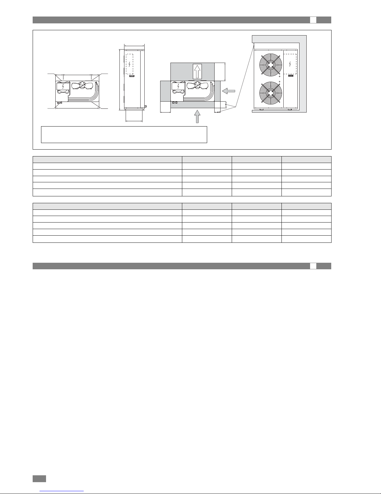
DIMENSIONAL DRAWINGS
I
600
W1
W2
W4
W3
900
D
B
C
=E
A
=
400
Dimensions 0011 0025 0041
A mm 900 900 900
B mm 640 940 1240
C mm 370 370 370
D mm 320 320 320
E mm 580 580 580
Weight distribution 0011 0025 0041
W1 kg 37 45 55
W2 kg 13 16 20
W3 kg 12 15 18
W4 kg 32 39 48
tot kg 95 115 140
1 - Hydraulic connections IN 0011÷0025 Ø 3/4” - 0041 Ø 1”1/4
2 - Hydraulic connections OUT 0011÷0025 Ø 3/4” - 0041 Ø 1”1/4
INSTALLATION
I
CHOICE OF INSTALLATION SITE
Before installing the unit, agree with the customer the site
where it will be installed, taking the following points into consideration:
- Check that the fixing points are adequate to support the
weight of the unit;
- Pay scrupulous respect to safety distances between the
unit and other equipment or structures to ensure that air
entering the unit and discharged by the fans is free to circulate.
- Follow the instructions shown in the chapter on DIMENSIONAL DRAWINGS to allow room for maintenance operations. If installing multiple units the clearances must be
doubled.
POSITIONING
Before handling the unit, check the capacity of the lift equipment used, respecting the instructions on the packaging.
To move the unit horizontally, make appropriate use of a lift
truck or similar, bearing in mind the weight distribution of the
unit.
To lift the unit, insert tubes long enough to allow positioning
of the lifting slings and safety pins in the special holes in the
base of the unit.
To avoid the slings damaging the unit, place protection
between the slings and the unit.
The unit should be installed on special vibration dampers.
See the chapter on DIMENSIONAL DRAWINGS for the support positions identified by W1, W2 etc. and the corresponding weights for the correct sizing of the vibration dampers.
Fix the unit, making sure it is level and that there is easy
access to water and electrical components.
If the site is exposed to strong winds, fix the unit adequately
using tie rods if necessary.
In heating mode the unit produces a significant quantity of
condensate, which must be suitably drained.
Condensate drainage must not cause problems to objects or
people.
If the outside air temperature is less than 0°C, the condensate may freeze; in these case fit a frost protection heater
on the drain line.
For correct operation of the unit, avoid the following: obstacles to air flow, leaves that may block the heat exchange
coil, strong winds that stop or reinforce air flow, sources of
heat too close to the unit, recirculation or stratification of air.
7
GB 03/2009 BRAN H
WATER CONNECTIONS
I A
The choice and installation of components is the responsibility of the installer who should follow good working practice
and current legislation. Before connecting the pipes, make
sure they do not contain stones, sand, rust, dross or other
foreign bodies which might damage the unit. Construction of
a bypass is recommended to enable the pipes to be washed
through without having to disconnect the unit (see drain
valves). The connection piping should be supported in such
a way as to avoid it weighing on the unit. The following components should be installed in the water circuit:
1. Two pressure gauges with a suitable scale (intake and
outlet);
2. Two vibration damper joints (intake and outlet);
3. Two shut off valves (normal in intake and calibrating in
outlet);
4. A flow switch (inlet). The flow switch must be calibrat-
ed by the installer to a value equal to 70% of rated
flow.
5. Two thermometers (intake and outlet);
6. An intake filter must be installed as close as possible
to the evaporator and positioned to allow easy access
for routine maintenance.
7. All the pipes must be insulated with suitable material to
prevent the formation of condensate and heat loss. The
insulating material must be a vapour barrier. Make sure
that the control and shut off devices protrude from the
insulation.
8. At the lowest points in the system, install drain valves for
easy emptying.
9. At the highest points in the system, install automatic or
manual air vent valves.
10. The unit is fitted as standard with an expansion vessel;
make sure this is correctly sized for the water content of
the system and the expected operating temperature, otherwise install an additional expansion vessel.
Failure to install the flow switches will mean the heat
exchangers are not protected in the event of no flow of liquid. Manufacturer cannot be held liable for any damage to
the unit and/or the system following the failure to install
these devices or the filter.
The correct operation of the components that help ensure
the safety of the appliance and the system should be
checked regularly.
Specifically, this involves cleaning the filters and checking
the operation of the flow switches installed.
Make sure that the frost protection heaters on the heat
exchanger are powered when the unit is off (unit in standby
“StbY”)
Water flow to the chiller unit must conform to the values
shown in the section on “General Technical Data”.
The flow of water must be maintained constant during operation.
The water content of the unit must be such as to avoid disturbing operation of the refrigerant circuits.
The unit must be prevented from freezing at outside air temperatures around 0°C.
It is recommended to use suitable percentages of antifreeze
(see “Water circuit data”), protect the piping with heating
sheaths, and empty the system, making sure there no water
remains at the lowest points in the circuit.
It is recommended to use non-toxic food grade antifreeze,
compliant with the standards in force in the countries where
the unit is used, if domestic hot water production is also featured.
9
2 4
1
15
16
11
15
7
2 3
5
6
T
6
T
F
1
1
13
13
14
8
1210
15
Installer connections
INSTALLATION WATER INLET
INSTALLATION WATER OUTLET
Factory connections
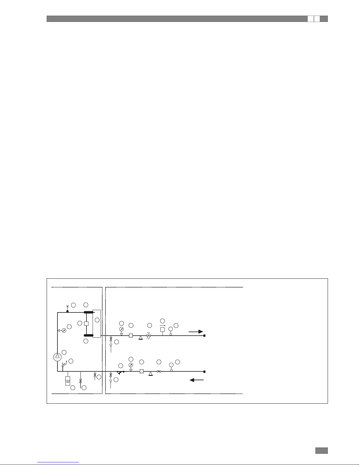
Utility water circuit connection diagram
1 Manometer
2 Anti-vibration joint
3 Interception valve
4 Calibration valve
5 Flow meter
6 Thermometer
7 Circulation pump
8 Safety valve
9 Air outlet
10 Expansion tank
11 Mesh filter
12 Fill/top-up
13 Temperature probe
14 Differential pressure guage
15 Drain/chemical washing valve
16 Plate heat exchanger
8
BRAN H GB 03/2009
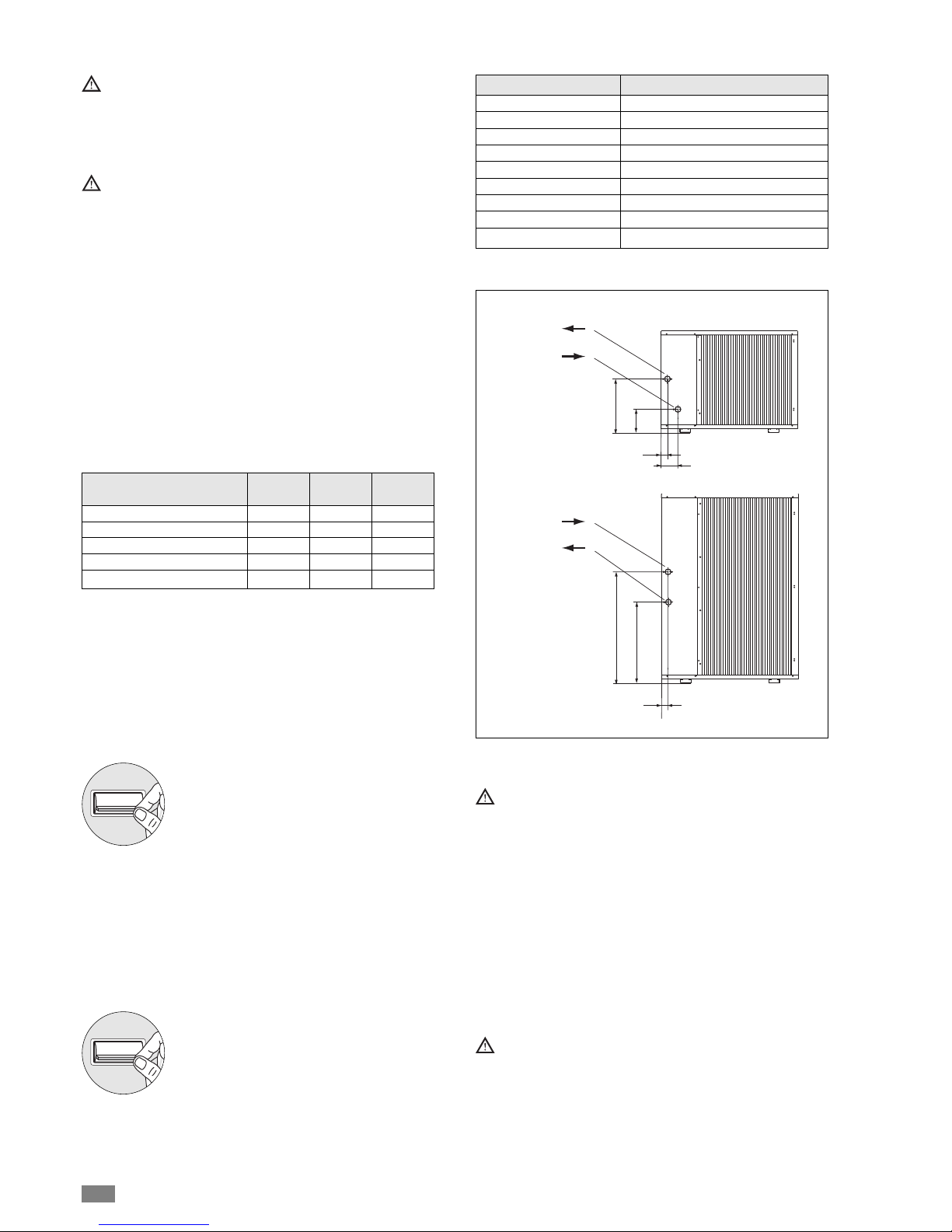
Size and position
0011 0025 0041
of connections
A (mm) 50 65 65
B (mm) 285 465 670
C (mm) 158 65 65
D (mm) 135 415 520
Hydraulic connections (Ø)
3/4" 3/4" 1"1/4
The heat pumps must be fitted with a filling/top-up system connected to the return line and a drain valve in the
lowest part of the system.
Systems containing antifreeze or covered by specific
legislation must be fitted with low-loss headers.
The manufacturer is not liable for obstruction, breakage
or noise resulting from the failure to install filters or
vibration dampers.
Particular types of water used for filling or topping up
must be treated with appropriate treatment systems.
For reference values, see the table.
CONDENSATE DRAIN
The unit is fitted with condensate pan; this must be connected to a drain system to take away the water that forms, see
the drawing.
If the outside air temperature is less than 0°C, the condensate drained from the collection pan may freeze.
The unit must be supported on a suitable structure or brackets to keep it off the ground, with a frost protection heater fitted on the drain line.
PH 6-8
Electrical conductivity less than 200 mV/cm (25°C)
Chlorine ions less than 50 ppm
Sulphuric acid ions less than 50 ppm
Total iron less than 0.3 ppm
Alkalinity M less than 50 ppm
Total hardness less than 50 ppm
Sulphur ions none
Ammonia ions none
Silicon ions less than 30 ppm
FILLING THE SYSTEM
- Before starting to fill, place the unit mains
switch QF1 in the OFF position.
- Before filling, check that the system drain
valve is closed.
- Open all system and terminal air vents.
- Open system shut off valves.
- Start filling by slowly opening the system water fill valve outside the unit.
- When water begins to leak out of the terminal air vent valves,
close them and continue filling until the pressure gauge indicates a pressure of 1.5 bar.
The system must be filled to a pressure of between 1
and 2 bars.
It is recommended that this operation be repeated after
the unit has been operating for a number of hours. The
pressure in the system should be checked regularly and
if it drops below 1 bar, the water content should be
topped-up.
Check the tightness of the joints.
EMPTYING THE SYSTEM
- Before starting to empty, place switch QF1
in the “OFF” position
- Make sure the system fill/top-up water
valve is closed.
- Open the drain valve outside the unit and
all the installation and terminal air vent
valves..
If the fluid in the circuit contains antifreeze, it should
not be allowed to drain freely, as it is pollutant.
It should be collected for possible reuse.
When draining after heat pump operation, take care as
the water may be hot (up to 50°).
ON
OFF
ON
OFF
A
C
B
D
water outlet
mod. 0011
mod.0025÷0041
water inlet
B
A=C
D
water outlet
water inlet
9
GB 03/2009 BRAN H
WATER CIRCUIT DATA
I A
Water content in the system
Size 0011 0025 0041
Minimum water content l 24 32 40
cPf
cQ
cdp
0
1
1
1
12%
0,985
1,02
1,07
20%
0,98
1,04
1,11
28%
0,974
1,075
1,18
35%
0,97
1,11
1,22
40%
0,965
1,14
1,24
Ethylene glycol solutions
Water and ethylene glycol solutions used as a heat carrier in
the place of water reduce the performance of the unit.
Multiply the performance figures by the values given in the
following table.
0 -5 -10 -15 -20 -25
Freezing point (°C)
Percentage of ethylene glycol in weight
cPf: capacity correction factor
cQ flow rate correction factor
cdp: pressure drop correction factor
f1: capacity correction factor
fk1: compressor power input correction factor
fx1: total power input correction factor
Fouling factors
The performance data given refer to conditions with clean
evaporator plates (fouling factor=1).
For different fouling factors, multiply the figures in the performance tables by the coefficient given in the following table.
4,4 x 10
-5
0,86 x 10
-4
1,72 x10
-4
0,96
0,93
0,99
0,98
0,99
0,98
Fouling factors
(m2°C/W) f1
Evaporator
fk1 fx1
0011 kPa 17 26 31 84 126 138 - - 0025 Pressure kPa 8 12 15 39 58 63 75 - 0041 drop kPa - 6 8 21 31 34 40 57 69
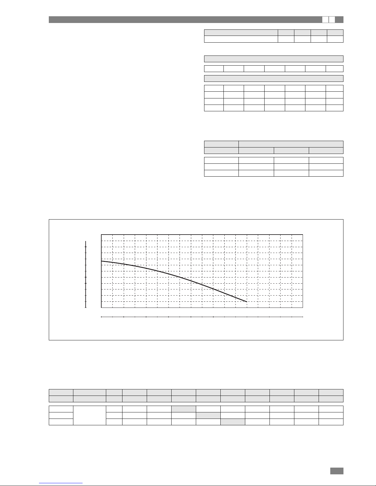
PUMP USEFUL HEAD CURVE (*)
(*) To obtain the useful head of the installation, subtract the pressure drop of the plate heat exchanger.
100
90
80
70
60
50
40
30
20
10
0
10,1
9,1
8,1
7,1
6,1
5,0
4,0
3,0
2,0
1,0
0
0,0 0,5 1,0 1,5 2,0 2,5 3,0 3,5 4,0 4,5 5,0 5,5 6,0 6,5 7,0 7,5 8,0 8,5 9,0 m3/h
0,13 0,27 0,41 0,55 0,69 0,83 0,97 1,11 1,25 1,38 1,52 1,66 1,80 1,94 2,08 2,22 2,36 2,5 L/s
KPamCA
HEAT EXCHANGER PRESSURE DROP (WATER SIDE)
Model Water m3/h 0,8 1,0 1,1 1,8 2,2 2,3 2,5 3,0 3,3
flow l/sec 0,223 0,278 0,306 0,501 0,612 0,640 0,696 0,835 0,919
Note: the values highlighted refer to the rated flow: external air 35°C - evaporator water 12/7°C
10
BRAN H GB 03/2009
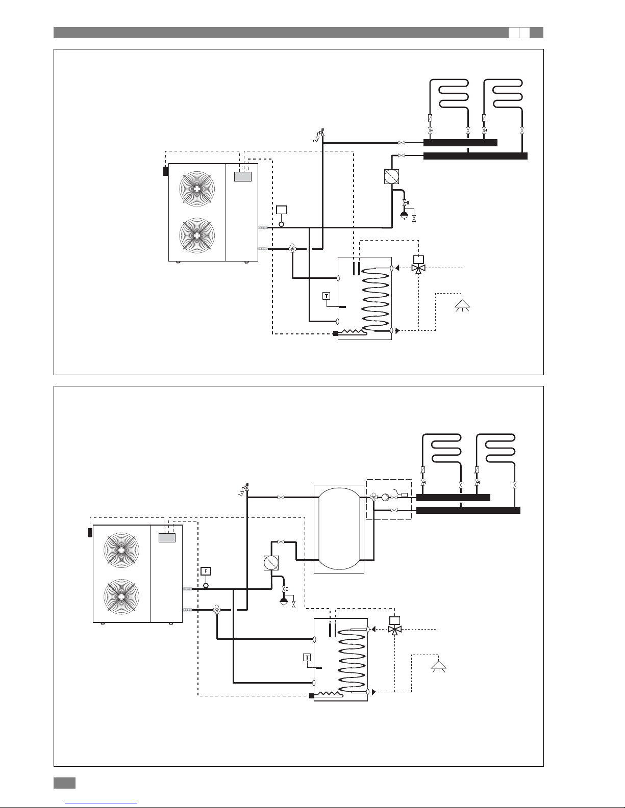
OPERATING DIAGRAMS
I A
5
4
6
2
3
2
3
11
12
97
8
M
10
F
1
13
M
14
2
12
13
3
2
3
M
5
4
6
11
14
97
8
M
10
1
15
M
16
The heat pump is connected directly to the central heating circuit (the minimum water
content required must be ensured).
The heat pump can also produce domestic hot water by managing a special 3-way
valve, connected to a hot water storage cylinder
The heat pump heats the water in the heating system storage cylinder.
The underfloor system is managed by the central heating pump, installed externally
to the storage cylinder, and by the mixer valve (unit 12).
The heat pump can also produce domestic hot water by managing a special 3-way
valve, connected to a hot water storage cylinder.
1 Heat pump
2 Non-return valve
3 Control valve with dial
4 Shut off valve
5 Expansion vessel (if necessary)
6 Air separator
7 DHW storage
8 Storage temperature sensor BT4
9 Thermostatic valve
10 Flow switch
11 Safety valve
12 Outside air temperature sensor
13 3-way valve, domestic hot water production
14 Electric heater
Example water circuit diagram
1 Heat pump
2 Non-return valve
3 Control valve with dial
4 Shut off valve
Expansion vessel (if necessary)
6 Air separator
7 DHW storage
8 Storage temperature sensor BT4
9 Thermostatic valve
10 Flow switch
11 Safety valve
12 Underfloor system control not supplied
13 System storage
14 Outside air temperature sensor
15 3-way valve, domestic hot water production
16 Electric heater
Example water circuit diagram
11
GB 03/2009 BRAN H
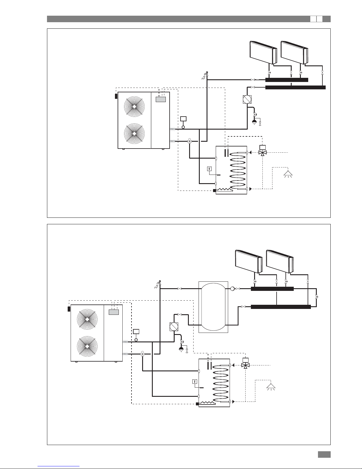
OPERATING DIAGRAMS
I A
3 3
5
4
6
11
12
97
8
M
10
F
1
13
M
14
12
3 3
13
5
4
6
11
15
14
97
8
M
10
F
1
16
M
17
The heat pump is connected directly to the central heating circuit (the minimum water content required must be ensured).
The heat pump can also produce domestic hot water by managing a special
3-way valve, connected to a hot water storage cylinder.
The heat pump heats the water in the heating system storage cylinder.
The underfloor system is managed by the central heating pump, installed
externally to the storage cylinder, and by the mixer valve (unit 12).
The heat pump can also produce domestic hot water by managing a special
3-way valve, connected to a hot water storage cylinder.
1 Heat pump
2 Non-return valve
3 Control valve with dial
4 Shut off valve
5 Expansion vessel (if necessary)
6 Air separator
7 DHW storage
8 Storage temperature sensor BT4
9 Thermostatic valve
10 Flow switch
11 Safety valve
12 Outside air temperature sensor
13 3-way valve, domestic hot water production
14 Electric heater
Example water circuit diagram
1 Heat pump
2 Non-return valve
3 Control valve with dial
4 Shut off valve
5 Expansion vessel (if necessary)
6 Air separator
7 DHW 3storage
8 Storage temperature sensor BT4
9 Thermostatic valve
10 Flow switch
11 Safety valve
12 Underfloor system control not supplied
13 System storage
14 Outside air temperature sensor
15 Bypass valve
16 3-way valve, domestic hot water production
17 Electric heater
Example water circuit diagram
12
BRAN H GB 03/2009
ELECTRICAL CONNECTIONS
I A
The heat pumps must be installed downstream of a main
switch (QF1, see wiring diagram), as required by the standards in force in the country where the unit is installed. Connection to the mains power supply and the connection of the
flow switch to the corresponding terminals must be performed by authorised personnel in compliance with the standards in force.
For all electrical work, refer to the electrical wiring diagrams
in this manual.
It is also recommended to check that:
- The characteristics of the mains electricity supply are adequate for the power ratings indicated in the electrical specifications below, also bearing in mind the possible use of
other equipment at the same time.
Power to the unit must be turned on only after installation work (plumbing and electrical) has been completed.
All electrical connections must be carried out by qualified personnel in accordance with legislation in force in
the country concerned
Respect instructions for connecting phase, neutral and
earth conductors..
The power line should be fitted upstream with a suitable
device to protect against short-circuits and leakage to
earth, isolating the installation from other equipment.
Voltage must be within a tolerance of ±10% of the rated
power supply voltage for the unit (for three phase units,
the unbalance between the phases must not exceed 3%).
If these parameters are not respected, contact the electricity supply company.
For electrical connections, use double insulation cable
in conformity with legislation in force in the country concerned..
A thermal overload switch and a lockable mains disconnect switch, in compliance with the CEI-EN standards (contact opening of at least 3mm), with adequate switching and residual current protection
capacity based on the electrical data table shown
below, must be installed as near as possible to the
appliance.
An efficient earth connection is obligatory.
The manufacturer cannot be held liable for any damage
caused by the failure to correctly earth the unit.
In the case of three phase units, ensure the phases
are connected correctly.
Do not use water pipes to earth the unit.
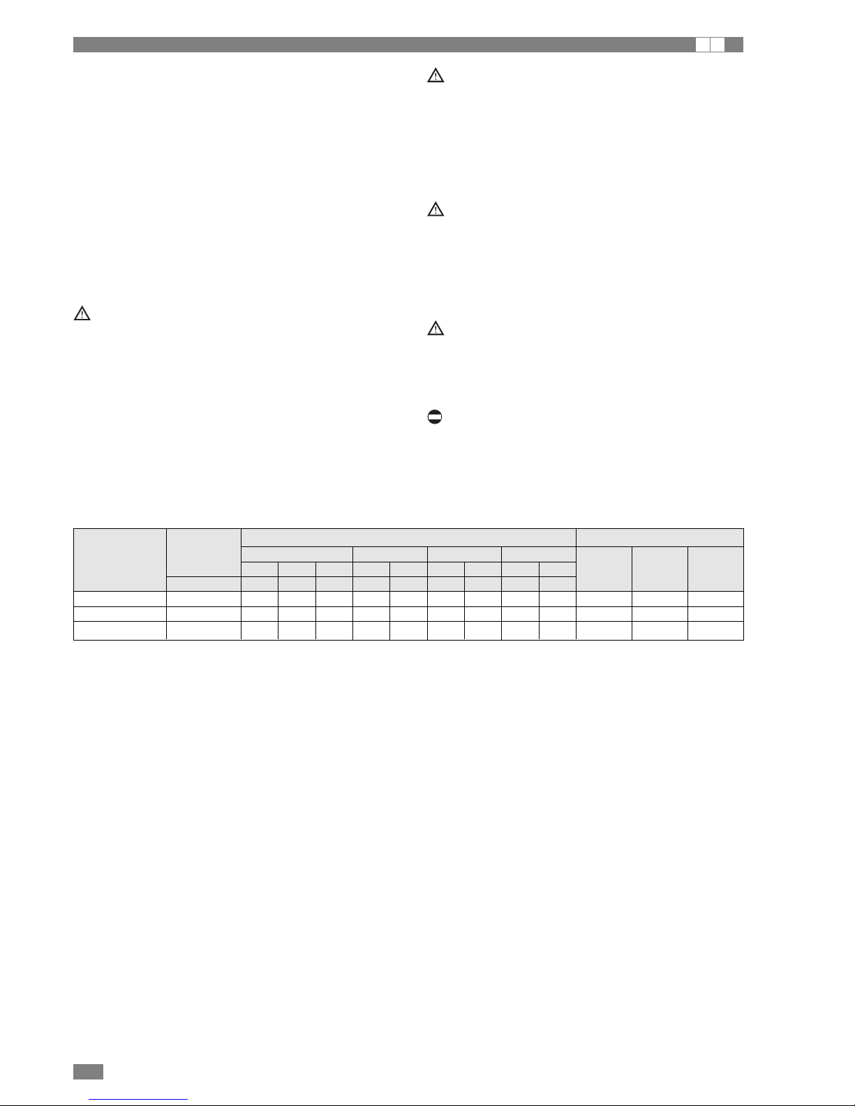
Electrical data at maximum conditions allowed (full load)
Size Power Maximum values Fuses (5x20T 250V)
elettrica Compressor Fan/Fans Pump Total
F.L.I. F.L.A. (1) F.L.I. F.L.A. F.L.I. F.L.A. F.L.I. F.L.A. FU1 FU2 FU3
(V-Ph-Hz) (kW) (A) (A) (kW) (A) (kW) (A) (kW) (A)
BRAN 0011M H 230~50 3,3 16 25 0,15 0,6 0,21 1 3,7 17,6 1,25 A 8 A 2 A
BRAN 0025M H 230~50 4,1 19 37 0,15 0,6 0,21 1 4,4 20,6 1,25 A 8 A 2 A
BRAN 0041M H 230~50 5,0 27 59 0,3 1,2 0,42 2 5,7 30,3 4 A 8 A 2 A
F.L.I Maximum power input
F.L.A. Maximum current input
(1) Start-up current
13
GB 03/2009 BRAN H
MAINS POWER SUPPLY CONNECTIONS
I A
- Before connecting the unit to the power supply, makes
sure that switch QF1 is open, suitably padlocked and
marked.
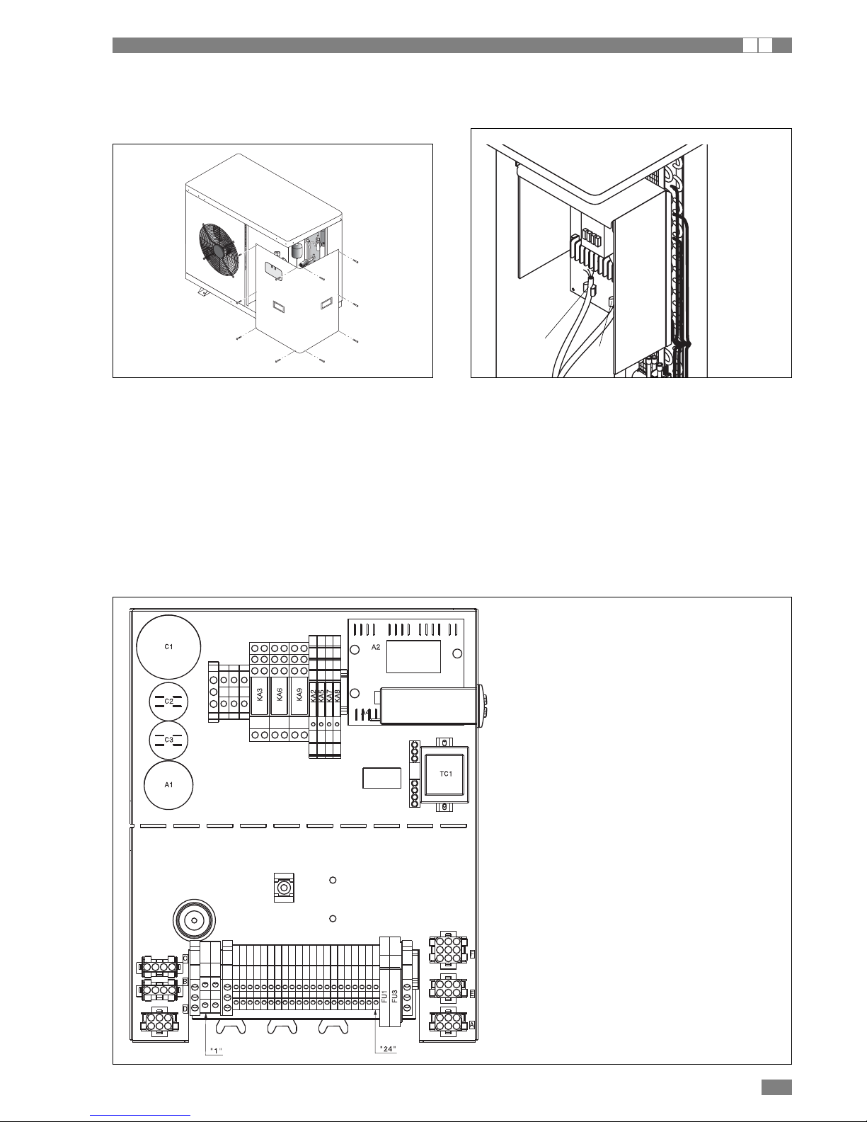
- Remove the inspection panel by unscrewing the screws.-
- Identify the terminals used for electrical connections on the layout drawing shown in this manual.
For the functional connection of the unit, bring the power supply cable to the electrical panel inside the unit and connect it to
terminals U-N for units 0025-0041, to terminals T1 and T3 on the disconnect switch for units 0011, respecting the (U) phase,
(N) neutral and (PE) earth in the case of single phase units (230V~50Hz), or U-V-W phases, N neutral and PE earth in three
phase units (400V-3N~ 50 Hz).
- Reposition the inspection panel.
- Check that all the covers removed to make the electrical connections have been replaced before powering up the unit.
- Place the main switch QF1 (outside the unit) in the “ON” position.
- The “POWER” LED on the control panel comes on to signal that power is connected.
- The message ON is shown on the HSW11 control panel, signalling that power is connected.
- Use cable gland A for the main electrical power cable and
cable gland B for other external cables to be connected by
the installer.
A
B
A3
ELECTRICAL PANEL LAYOUT
A1 Noise suppression lter
A2 Condensing fan control board
A3 Electronic control
C1 Compressor starting capacitor
C2-3 Fan starting capacitor
FU1 Plant water pump protection fuse
FU2 Fan protection fuse
FU3 Auxiliary circuit protection fuse
KA2 Boiler relay
KA3 High pressure switch relay
KA5 3 ways valve relay
KA6-8 Compressor relay
KA7 Alarm relay
KA9 Pump relay
TC1 230/24/12 VAC transformer
 Loading...