

Delmhorst FX-2000/1986, FX-2000/10/PKG, FX-2000/1986/40, FX-2000/36/PKG, FX-2000/HT/PKG User manual
...Page 1
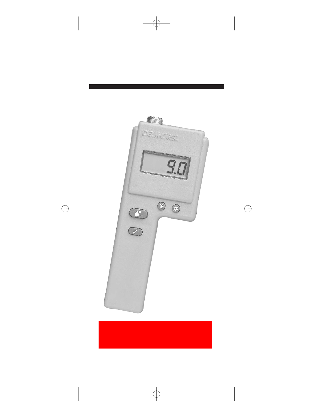
FX-2000
owners manual
WHEN ACCURACY IS THE POINT.
®
TM
FX-2000 B&W manual:FX-2000 B&W manual 50406Q5 12/10/08 8:57 A
Find Quality Products Online at: [email protected]
www.GlobalTestSupply.com
Page 2

TABLE OF CONTENTS
2 FX-2000 Features
3 Before You Begin
3 To Use Meter In The Portable Mode
3 Check Calibration
4 Change the Set-Point
4 To Check Accumulated Readings
5 To Operate The Backlight
6 To Reset Meter
6 Taking a Reading
6 Testing Baled Hay
6 Notes
7 Testing in the Windrow
8 Factors Affecting Your Reading
9 Range of Moisture Content
9 Hay Temperature
10 Curing
10 Density
10 Use of Preservatives
11 Sample Size
11 To Use Meter For Continuous Monitoring
12 To Install The #1986 Bale Sensor
13 Installation on an Inline or Center Line
Small Square Baler
13 Installation on a Large or Mid-size Baler
13 Installation on a John Deere Round Baler
14 Installation on a New Holland or Case RBX
FX-2000 B&W manual:FX-2000 B&W manual 50406Q5 12/10/08 8:57 A
Round Baler
14 Installation on all other
15
o Use Meter in the Continuous Mode
T
15 About Your Readings
16 Care of Your Meter
16 Warranty
Round Balers
Find Quality Products Online at: [email protected]
www.GlobalTestSupply.com
Page 3
%
FX-2000 FEATURES
h6% to 40% moisture range (starting with serial number
19569)
hDigital readout
hBuilt-in calibration check
hTemperature stable circuit
hErgonomic case design
hIncludes (1) 9-volt battery
hThree year warranty
h60 years of proven quality, accuracy and service
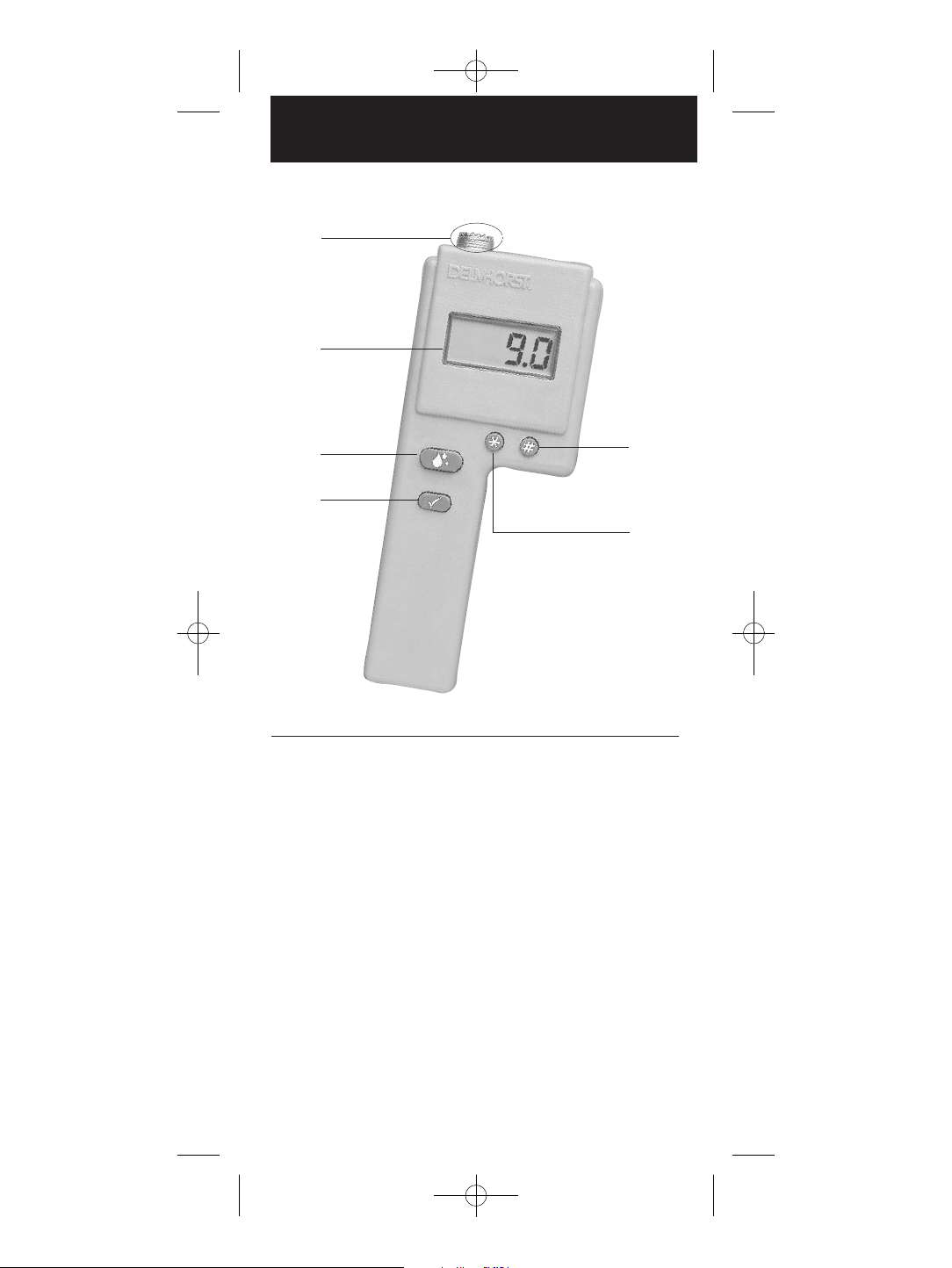
Digital Readout
Read Button
Calibration
Check Button
$
Set-Point
Increase
#
Set-Point
Decrease
@
External Connector
^
!
DELMHORST FX-2000
2
FX-2000 B&W manual:FX-2000 B&W manual 50406Q5 12/10/08 8:57 A
Find Quality Products Online at: [email protected]
www.GlobalTestSupply.com
Page 4

BEFORE YOU BEGIN
Button Functions
! Read Button - Reads the percent moisture con-
tent value %MC when the meter is in the
portable mode. Turns the meter on in the
continuous mode.
@ Calibration Check Button - Checks the meter
calibration. Displays the average of up to 100
accumulated readings; displays the highest
stored reading; erases the readings (portable
mode only). Turns the meter off in the continuous mode.
# Set-Point Decrease Button - Allows you to
decrease the set-point to a lower value.
$ Set-Point Increase Button - Allows you to
increase the set-point to a specific %MC. A
buzzer will alert you if the meter reads higher
than the selected %MC. Also operates the backlight in the portable mode.
When the battery is replaced, the meter displays its
software version for one second and then turns itself
off. After replacing the battery, you must reset the
meter as described on page 6.
TO USE THE METER IN THE
PORTABLE MODE:
Please read this section carefully. In the portable mode, the
FX-2000 has different functions than in the continuous mode.
CHECK CALIBRATION
hRemove the probe from the top of the meter.
hPress and hold the read button
! and check button @
simultaneously. Meter is in calibration if it displays “12”
(± .2) regardless of the scale setting.
3
FX-2000 B&W manual:FX-2000 B&W manual 50406Q5 12/10/08 8:57 A
Find Quality Products Online at: [email protected]
www.GlobalTestSupply.com
Page 5
CHANGE THE SET-POINT
hTo change the set-point value press the set-point increase
button
$. The meter will display the current set-point
value.
hTo scroll forward to a higher value, hold the set-point
increase button
$ while the current value is displayed
and scroll up to the set-point value desired.
hTo scroll backward through the set-point values, press and
release the set-point increase button
$. Within one sec-
ond press and hold the set-point decrease button
#.
hContinue to hold the set-point decrease button
# and the
set-point value will decrease.
hWhen scrolling in either direction, release the button to
stop at your desired set-point.
If the meter reads a %MC higher than that of the set-point,
a buzzer will sound.
TO CHECK ACCUMULATED
READINGS
This feature allows you to view the total number of all
accumulated readings, the average of those readings, and the
highest stored reading.
hTo add a reading to the sum of all previously stored readings,
release the read button
! within 2 seconds. If you press
and hold the read button
!, the meter will repeat its read
cycle, but will not add a new reading to the storage until
the button is released.
hTo view the readings press and release the calibration
check button
@. First the meter displays the number of
accumulated readings for one second, then the average of
those readings for two seconds. Then it displays the highest
stored reading for two seconds. The total “cycle” time is
five seconds.
4
FX-2000 B&W manual:FX-2000 B&W manual 50406Q5 12/10/08 8:57 A
If you check the calibration and the display does not read
“12,” it is likely an indication of a low battery. If this
occurs, change the battery immediately. Continued use with a
low battery may cause the meter to go out of calibration. If
you have a fresh battery and the instrument still does not
indicate an acceptable calibration, return it to DELMHORST
for service.
Find Quality Products Online at: [email protected]
www.GlobalTestSupply.com
Page 6

5
hTo erase all the accumulated readings, hold the calibration
check button
@ for more than 5 seconds until the meter
displays “0”.
hTo keep the accumulated readings in memory, release the
calibration check button
@ before the total cycle time is
complete.
The meter will accumulate up to 100 readings. After all
100 readings are stored, it will not add new readings until
the memory has been cleared. It will also continue to display
the average of all 100 readings as a reminder that the
memory is full.
Readings below 6% will be displayed as “.0”. Those above
40% will be displayed as “99.9.” Neither will be added to
the accumulated readings or used in calculation of average or
highest reading.
TO OPERATE THE BACKLIGHT
hPress and release the calibration check button @. Within
one second, press and hold the set-point increase button
$.
hHold the set-point increase button
$ until the backlight
turns on. The backlight will be activated and remain lit as
long as the meter remains on. After the meter turns off,
the backlight will also turn off.
hThe backlight will remain activated while the meter is off
and will light up when any function is activated.
hTo deactivate the backlight, repeat the same steps taken to
activate it.
If there are readings stored in memory, the meter will
run through the check cycle while activating the backlight. If no readings are stored, it will display “0”.
The backlight will be deactivated automatically when changing from the portable mode to the continuous mode.
Use of the backlight should be kept to a minimum to avoid
draining the battery.
FX-2000 B&W manual:FX-2000 B&W manual 50406Q5 12/10/08 8:57 A
Find Quality Products Online at: [email protected]
www.GlobalTestSupply.com
Page 7

TO RESET METER
hPress and release the calibration check button @.
hWithin one second, press and hold the set-point decrease
button
#.
hThe meter will reset itself and display “222.” It will also
reset the set-point to 19% and clear all of the readings
stored in memory.
Note: The meter will also reset itself if you change from the
portable mode to the continuous mode.
TAKING A READING
Testing Baled Hay
hConnect the probe to the external connector on the top of
the meter
^.
hInsert the probe into the bale.
hPress the read button
!. The meter displays the %MC for
two seconds.
Notes
hThe hay prod is electrically insulated, except at the metal
points near the tip. The moisture content measured represents the hay in contact with the tip of the prod only.
hPartially cured hay may have wide variations in moisture
content throughout the bale. Readings should be taken in
several different parts of the bale and the highest readings
used as a guideline. The arrangement and compaction of
hay fibers in a bale may have an effect on meter readings.
hIf you are testing high density bales, we recommend using
the H-4 handle with the 830-2 10" prod, 830-3 18" prod,
or the 830-4 36" prod. Using the handle/prod combination
eliminates excess stress on the instrument case that may
occur when trying to insert the prod into a high density or
large bale.
hWhen using the 36" prod, be sure to guide the prod into
the bale with one hand while pushing on the H-4 handle.
6
FX-2000 B&W manual:FX-2000 B&W manual 50406Q5 12/10/08 8:57 A
Find Quality Products Online at: [email protected]
www.GlobalTestSupply.com
Page 8

Testing in the Windrow
There are three ways to test moisture content in the windrow:
Test A
hAttach the #831 short pin prod to the H-4 handle and
connect the handle to the external connector on top of the
meter.
hPrepare a representative sample by collecting hay from
various parts of the windrow.
hPlace hay in a non-conductive container (such as a 5 to 10
gallon plastic pail) and apply the short pin prod to the hay.
hPress down on the electrode to make firm contact with the
hay sample.
hPress the read button
! and take a reading.
hMix the sample once again and take at least two more
readings. Use the highest readings.
Notes
hWhenever pressure is being applied on the electrode, be sure
that the points of the electrode are touching nothing but the
hay.
hRepeat the steps above if considerable variations are found
in the meter readings. To reduce these variations, chop the
hay, mix it thoroughly and take several readings by following the procedures above. This will make the moisture
distribution in the sample more uniform.
7
FX-2000 B&W manual:FX-2000 B&W manual 50406Q5 12/10/08 8:57 A
Find Quality Products Online at: [email protected]
www.GlobalTestSupply.com
Page 9

Test B
hAttach the #831 short pin prod to the H-4 handle and
connect the handle to the external connector on top of the
meter.
hPress down on the prod to make firm contact with the hay
sample.
hPress the read button
! and take a reading.
hMake several tests on the hay exposed to the sun, then
turn the windrow over and make an equal number of tests
on the hay that had been closer to the ground. Use the
highest readings.
Notes
hMake sure that the points of the electrode are not touching
the ground. The electrode points should make contact with
the hay only.
Test C
hSelect up to five large, slower-drying stems from a section
of the windrow.
hPlace them one at a time across two adjacent points on
the #831 short pin prod.
hThe average of these stem readings should be about two to
five points higher than the actual moisture content.
Notes
hRepeat these steps in different parts of the field and pay
special attention to the areas where the hay is heaviest.
hThe amount of variation found among windrow readings as
well as the average stem moisture should be taken into
consideration before the decision is made to start baling.
FACTORS AFFECTING YOUR
READINGS
Because of the many variables that affect the electrical
meter readings, the indicated moisture content should not be
used as an absolute quantitative measurement. Meter readings are very useful guidelines for safe storability of hay.
8
FX-2000 B&W manual:FX-2000 B&W manual 50406Q5 12/10/08 8:57 A
Find Quality Products Online at: [email protected]
www.GlobalTestSupply.com
Page 10

9
Meter readings become more significant when they are
considered in the light of the density of the bales, anticipated
handling and storage, and prevailing climate conditions.
Range of Moisture Content
The FX-2000 is designed to test moisture in hay over a range
of 6%-40%. Readings over 30% should be used only as a
qualitative indication of high moisture content. Delmhorst
moisture meters use the relationship existing between electrical
conductivity and moisture content in hay. As moisture content
increases, so does the conductivity.
Tests on hay at high moisture content, over 25%, are less
accurate. This is mostly due to the variability in moisture
distribution. The reduced level of accuracy in the high range
does not significantly affect the usefulness of the meter, as a
few high readings indicate that some action be taken to dry
the hay to avoid spoilage or even self-combustion.
While it is important to note the average of several readings,
it is even more important to note the high readings and the
frequency at which they occur.
Hay Temperature
The FX-2000 has been calibrated at 80°F on various samples
of different types of hay, mostly alfalfa, and on different
cuttings and mixtures. The higher the temperature of the
sample, the higher the meter readings will be. Temperatures
lower than 80°F cause lower meter readings. The correction
is approximately 1% point for every 20° difference. Refer to
chart on the next page:
Hay temperature Add to reading Subtract from reading
20°F/-7°C 3 -40°F/ 5°C 2 -60°F/15°C 1 -80°F/30°C 0 0
100°F/40°C -- 1
120°F/50°C -- 2
140°F/60°C -- 3
Example
Meter reading: 22%
Temperature: 40°F/5°C
Moisture Content: 24% (22 + 2)
FX-2000 B&W manual:FX-2000 B&W manual 50406Q5 12/10/08 8:57 A
Find Quality Products Online at: [email protected]
www.GlobalTestSupply.com
Page 11

10
Curing
Before proper curing has taken place, wide variations in
moisture content should be expected in both recently baled
hay and hay in the windrow. These variations will be exposed
by meter readings taken on different parts of the windrow or
bale. The higher the moisture range, the wider are the
variations. The more curing has been allowed to take place,
the greater uniformity in moisture distribution can be
expected.
The validity of the meter readings is closely related to the
care spent in sampling the hay to be tested. Whether hay in
the windrow or baled hay is tested, the number of tests made
should be increased whenever the initial readings show
considerable variations.
Density
The calibration of the moisture testers applies to bales of
normal “average’ density. Generally:
hDenser bales may yield readings 1-2% points higher.
hLooser bales tend to yield 1-2% point lower.
hTests in stacks usually yield readings 2%-3% lower.
hTests on grass hay may yield readings about 3% lower.
Baling should be done according to the lower meter reading.
When testing baled hay, drive the prod across the slices of
the bale, not between them. This will ensure firmer and more
uniform contact.
When using the short pin prod, uniformity of pressure from one
sample to the other is achieved by applying pressure to the “pressure button” at the end of the H-3 handle as described on page 7.
Use of Preservatives
Hay preservative or stabilizers may also have an affect on
meter readings. Normally a bale of hay treated with preservative will read higher than a bale of the same hay that had
not been treated. The readings typically increase by 2-4%
points, and 24-48 hours after treatment, the readings
between the bales tends to equalize.
FX-2000 B&W manual:FX-2000 B&W manual 50406Q5 12/10/08 8:57 A
Find Quality Products Online at: [email protected]
www.GlobalTestSupply.com
Page 12

Occasional higher readings may occur if, in addition to the
effect of the increased conductivity due to the stabilizer, the
bales tested also show an increase in temperature and
“sweating.” As the stabilizer becomes more thoroughly
absorbed and the sweating subsides, the meter readings
recede to the initial level and will continue to decrease,
assuming that the bale becomes progressively dryer.
Sample Size
When testing baled hay, it is essential to take readings at
several different points in the bale. Hay moisture may vary a
great deal in the same bale. For example, at one point bale
moisture may be 20% and at another over 35%.
More tests must be made whenever the variations among
readings are greater. If there is a possibility of high moisture
areas, samples from these locations should be taken. Areas of
high moisture content will spoil, resulting in loss.
It is extremely important to note the high readings and the
frequency at which they occur.
TO USE THE METER FOR
CONTINUOUS MONITORING
To install the meter:
hAttach the red lead of the power cable to a positive (+)
12-volt supply point controlled by the ignition switch or
attach it directly to the tractor battery.
hGround the other lead. A replaceable fuse protects the circuit.
The meter can also be powered independently of the tractor’s electrical system by using a 12V, (Eveready 732 or
equivalent) all-purpose battery.
hSelect a location in the cab where the display can be easily
viewed while baling. Install the stainless steel mounting
loop and slide the meter onto the loop.
hConnect the power cable to the meter.
11
FX-2000 B&W manual:FX-2000 B&W manual 50406Q5 12/10/08 8:57 A
Find Quality Products Online at: [email protected]
www.GlobalTestSupply.com
Page 13
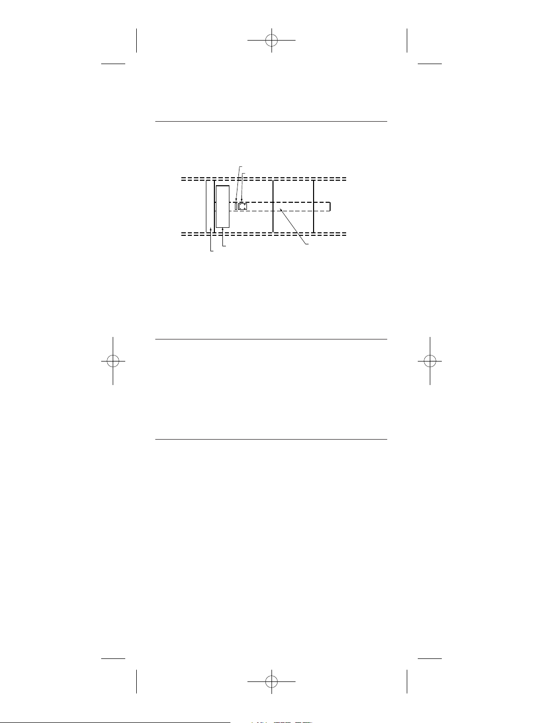
To install the #1986 bale sensor:
Installation on a conventional small square baler:
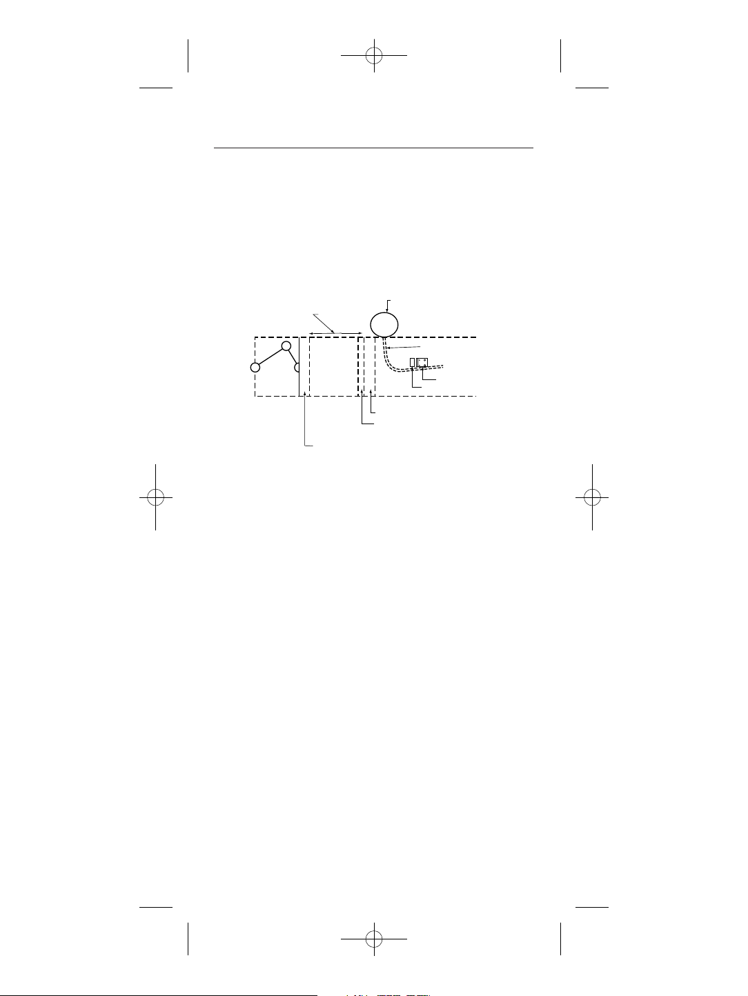
hLocate a spot on either side of the bale chamber, approxi-
mately halfway up the side of the bale, 12" to 24" in from
the rear of the chamber. The sensor pad and crop diverter
need to be located in the baler chamber as close to the
plunger face as possible. The sensor must mount flat.
hTape the drilling template onto the location. Make sure
before drilling that when the bolts come through the side
of the chamber that they do not interfere or touch any
other pieces of metal. Using the size drill indicated, drill
the mounting holes. File any burrs from the holes.
hInstall the sensor plate with only the bale chamber wall
between it and the backplate. The beveled edge of the insulation must face the plunger (opposite direction of bale
movement).
hSlide the coaxial cable lugs between two flat washers.
Secure all six nuts.
hSecure the coaxial cable at several points with tape or
nylon ties so that it does not interfere with any moving
parts of the baler.
hConnect the coaxial sensor cable to the meter.
12
FX-2000 B&W manual:FX-2000 B&W manual 50406Q5 12/10/08 8:57 A
Cutaway View of Conventional Square Baler Chamber
(viewed from plunger side of machine)
FEED OPENING
PLUNGER POSITION (RETRACTED)
KNOTTERS
TWINE FEEDER
SENSOR PAD
DIVERTER
PLUNGER POSITION (EXTENDED)
KNIFE
Find Quality Products Online at: [email protected]
www.GlobalTestSupply.com
Page 14
13
Installation on an Inline or
Center Line small square baler:
hFollow instructions for installation as above.
If placing the #1986 in the center channel you may need to
cut an opening from the outside to be able to tighten down
the nuts and secure the wire or use longer bolts and spacers.
Installation on a large or
mid-size square baler:
When installing the #1986 on a large square baler, use the
same guidelines as above. However, we recommend that you
add a 1/4" thick piece of strap iron in front of the sensor’s
beveled edge. This will provide additional protection to the
sensor plate.
Installation on a John Deere
Round Baler:
hLocate a spot on the right hand side of the bale chamber,
approximately 4.5" up from the bottom of the frame. The
back edge of the sensor pad should be vertical so that the
top rear corner of the sensor pad is approximately 3/8"
forward from the rear edge of the upright frame tube.
hFollow instructions for installation as above.
Make sure that the beveled edge of the sensor pad is facing the front of the baler.
FX-2000 B&W manual:FX-2000 B&W manual 50406Q5 12/10/08 8:57 A
Top View of Inline or Centerline Small Square Baler
Front
of
Machine
DIVERTER
SENSOR PAD
AREA OF KNOTTERS
PLUNGER POSITION (EXTENDED)
CENTER CHANNEL
Find Quality Products Online at: [email protected]
www.GlobalTestSupply.com
Page 15
V
Install sensor here
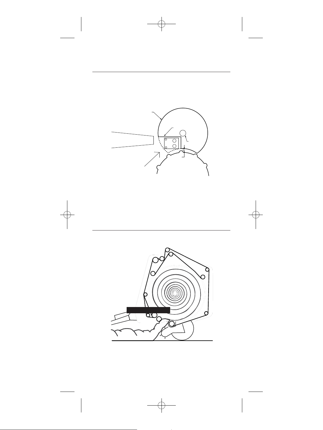
Installation on a New Holland
or Case RBX Round Baler:
hLocate a spot on either side of the bale chamber.
hYour baler may contain a circular crop diverter plate. If it
does, a notch must be cut out of the plate so that the sensor can rest against the chamber wall.
hFollow instructions for installation as above.
Make sure that the beveled edge of the sensor pad is facing the front of the baler.
Installation on all other Round
Balers:
hLocate a spot on the side wall or tailgate, on either side of
the baler, as low as possible to the bottom.
hFollow instructions for installation as above.
Be sure the sensor plate lies flat, with the beveled edge
facing the pickup. The hay will begin to pass over the
sensor when the bale is formed to approximately ¼ of
full size.
CROP DIVERTER PLATE
(SOME MODELS MAY NOT HAVE)
MUST MAKE CUTS
FLOW FROM
PICK-UP
CARRIAGE BOLTCARRIAGE BOLTCARRIAGE BOLT
0.5 INCH
14
FX-2000 B&W manual:FX-2000 B&W manual 50406Q5 12/10/08 8:57 A
Find Quality Products Online at: [email protected]
www.GlobalTestSupply.com
Page 16

TO USE THE METER IN THE
CONTINUOUS MODE
hChange the set-point to the desired value as described on
page 4. This must be done prior to turning the meter on.
hPlug the external power supply into the side of the meter.
This will automatically put the meter in the continuous
mode. Once power is supplied, the backlight will turn on
and remain on until the external power is removed.
hTurn the meter on by pressing the read button
!. A deci-
mal point will display for a few seconds and then the meter
will begin displaying the average and highest readings.
When the meter is operating continuously, it takes two
readings every second, and accumulates eight readings
before calculating their AVERAGE and HIGHEST values. After all eight readings have been taken, the meter
will begin a new read cycle. The meter displays the aver-
age as Axx.x and the highest as xx.x alternately for two
seconds each.
hTurn the meter off by either removing the external power
supply or pressing and holding the calibration check button
@ until the meter is off. The backlight will stay on until
the power supply is removed.
Notes
hStart tractor before powering up meter.
hDisconnect meter before shutting down tractor.
ABOUT YOUR READINGS
The meter reads between 6% and 40%. Readings below 6%
are displayed as “.0” and are used in calculation as 7.5%;
readings above 40% are displayed as “99.9” and are used in
calculation as 45%.
Readings obtained while using the FX-2000 in its continuous
mode are usually higher than those obtained when probing
the bale by hand. Under normal conditions, expect the continuous readings to be around 2-4 points higher on average.
Tests show this difference can be even greater, especially on
large square bales, depending on overall conditions.
Do not be concerned that such differences exist. However, it
is important to have a feel for what the difference is since
conditions in the field change rapidly.
15
FX-2000 B&W manual:FX-2000 B&W manual 50406Q5 12/10/08 8:57 A
Find Quality Products Online at: [email protected]
www.GlobalTestSupply.com
Page 17

We recommend that you spot check the windrow and freshly
made bales to give additional information with regard to
these differences and to help establish the appropriate range
for baling.
CARE OF YOUR METER
To keep your meter in good working order:
hStore your meter in a clean, dry place. The optional
protective carrying case is an ideal storage place when
the meter is not in use.
hChange the 9-Volt battery as needed. Continued use with a
low battery may cause the meter to go out of calibration.
hClean the meter and probe with any biodegradable cleaner.
Use the cleaner sparingly and on external parts only. Do
not immerse the meter or any prod in water.
hRemove the battery if the meter will not be used for one
month or longer.
WARRANTY
16
FX-2000 B&W manual:FX-2000 B&W manual 50406Q5 12/10/08 8:57 A
Delmhorst
Delmhorst, guarantees its FX
from date of purchase and any optional electrodes against
defects in material or workmanship for 90 days. This limited
warranty does not cover abuse, alteration, misuse, damage
during shipment, improper service, unauthorized or unreason-
able use of the meter or electrodes. This warranty does not
cover batteries, pin assemblies, or pins. If the meter or any
optional electrodes have been tampered with, the warranty
shall be void. At our option we may replace or repair the
meter.
Delmhorst shall not be liable for incidental or consequential
damages for the breach of any express or implied warranty
with respect to this product or its calibration. With proper care
and maintenance the meter should stay in calibration;
follow the instructions in the Care of Your Meter section.
Under no circumstances shall Delmhorst be liable for any
incidental, indirect, special, or consequential damages of any
type whatsoever, including, but not limited to, lost profits or
downtime arising out of or related in any respect to its
Instrument Co., referred to hereafter as
-2000 meter for three years
Find Quality Products Online at: [email protected]
www.GlobalTestSupply.com
Page 18

meters or electrodes and no other warranty, written, oral or
implied applies. Delmhorst shall in no event be liable for any
breach of warranty or defect in this product that exceeds the
amount of purchase of this product.
The express warranty set forth above constitutes the entire
warranty with respect to Delmhorst meters and electrodes
and no other warranty, written, oral, or implied applies. This
warranty is personal to the customer purchasing the product
and is not transferable.
17
FX-2000 B&W manual:FX-2000 B&W manual 50406Q5 12/10/08 8:57 A
Find Quality Products Online at: [email protected]
www.GlobalTestSupply.com
Page 19

WHEN ACCURACY IS THE POINT.
®
TM
For 60 years Delmhorst has been
the leading manufacturer of high
quality moisture meters and thermo-
hygrometers. Today we offer the
innovative KIL-MO-TROL
®
in-kiln
monitoring system. We also offer a
wide range of meters for a variety
of applications including wood-
working/lumber, agriculture, con-
struction, paper, restoration, IAQ
and flooring.
FX-2000 B&W manual:FX-2000 B&W manual 50406Q5 12/10/08 8:57 A
Find Quality Products Online at: [email protected]
www.GlobalTestSupply.com
 Loading...