

Page 1
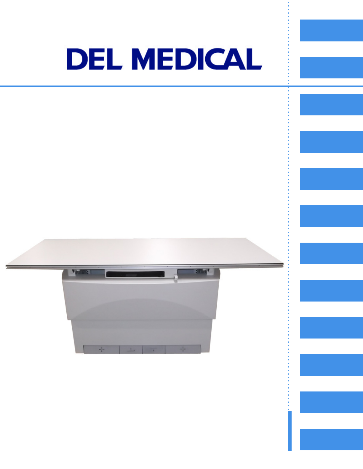
EV-800
Table of
Contents
Safety
Introduction
Elevating Table
Installation, Operation,
& Service Manual
Installation
Operation
Periodic
Maintenance
Maintenance
Component
Replacement
P/N 8000-EV800-D
Revision: A, March 6, 2012
TroubleShooting
Electrical
Schematics
Illustrated
Parts List
Notes
Page 2
Copyright 2012, Del Medical Inc. All rights reserved.
This document is the property of Del Medical Inc. and contains confidential and proprietary
information owned by Del Medical Inc. Any unauthorized copying, use or disclosure of it without the
prior written permission of Del Medical Inc. is strictly prohibited.
Attention: Consult accompanying documents as necessary.
Del Medical Inc.
50B North Gary Avenue Phone:1-847-288-7000
Roselle, IL 60172 Fax:1-847-288-7011
USA Toll Free:1-800-800-6006
www.delmedical.com
Page 3

Table of Contents
Safety Information
Introduction. . . . . . . . . . . . . . . . . . . . . . . . . . . . . . . . . . . . . . . . . . . . . . . . i–1
Statement of Liability. . . . . . . . . . . . . . . . . . . . . . . . . . . . . . . . . . . . . . . . i–2
Definitions . . . . . . . . . . . . . . . . . . . . . . . . . . . . . . . . . . . . . . . . . . . . . . . . . i–3
Safety Conventions Used in this Manual . . . . . . . . . . . . . . . . . . . . . . . i–4
Warning Statements . . . . . . . . . . . . . . . . . . . . . . . . . . . . . . . . . . . . . i–4
Caution Statements. . . . . . . . . . . . . . . . . . . . . . . . . . . . . . . . . . . . . . i–5
Equipment Safety Guidelines . . . . . . . . . . . . . . . . . . . . . . . . . . . . . . . . . i–6
Emergency Stop Button (For Service Technicians Only) . . . . . . . . . . i–9
Electrical Discharge (For Service Technicians Only). . . . . . . . . . . . . i–10
Identification Labels. . . . . . . . . . . . . . . . . . . . . . . . . . . . . . . . . . . . . . . . i–11
EV-800 Label . . . . . . . . . . . . . . . . . . . . . . . . . . . . . . . . . . . . . . . . . . i–11
Product Life. . . . . . . . . . . . . . . . . . . . . . . . . . . . . . . . . . . . . . . . . . . . . . . i–12
Record of Revisions
Revision History . . . . . . . . . . . . . . . . . . . . . . . . . . . . . . . . . . . . . . . . . . . . ii–1
List of Affected Pages . . . . . . . . . . . . . . . . . . . . . . . . . . . . . . . . . . . . . . .ii–1
Chapter 1 — Introduction
1.1 Introduction. . . . . . . . . . . . . . . . . . . . . . . . . . . . . . . . . . . . . . . . . . . . . 1–1
1.2 Description . . . . . . . . . . . . . . . . . . . . . . . . . . . . . . . . . . . . . . . . . . . . . 1–2
1.3 Dimensions . . . . . . . . . . . . . . . . . . . . . . . . . . . . . . . . . . . . . . . . . . . . . 1–3
1.4 Minimum Space Requirements . . . . . . . . . . . . . . . . . . . . . . . . . . . . 1–5
1.5 Specifications. . . . . . . . . . . . . . . . . . . . . . . . . . . . . . . . . . . . . . . . . . . . 1–6
1.6 Abbreviations . . . . . . . . . . . . . . . . . . . . . . . . . . . . . . . . . . . . . . . . . . . 1–7
1.7 Optional - Accessories . . . . . . . . . . . . . . . . . . . . . . . . . . . . . . . . . . . . 1–8
Chapter 2 — Installation
2.1 Installation Instructions. . . . . . . . . . . . . . . . . . . . . . . . . . . . . . . . . . . 2–1
PBL Option Installation . . . . . . . . . . . . . . . . . . . . . . . . . . . . . . . 2–7
Ion Chamber Option Installation . . . . . . . . . . . . . . . . . . . . . . 2–11
Grid Installation. . . . . . . . . . . . . . . . . . . . . . . . . . . . . . . . . . . . . 2–16
Testing Collision Avoidance Switches . . . . . . . . . . . . . . . . . . 2–29
Cassette Tray Insertion . . . . . . . . . . . . . . . . . . . . . . . . . . . . . . . 2–31
i
Page 4

EV800 Elevating Table Installation, Operation, and Service Manual
Chapter 3 — Operation
3.1 Safety Precautions. . . . . . . . . . . . . . . . . . . . . . . . . . . . . . . . . . . . . . . .3–1
3.2 Operation Specifications . . . . . . . . . . . . . . . . . . . . . . . . . . . . . . . . . .3–4
3.3 Controls . . . . . . . . . . . . . . . . . . . . . . . . . . . . . . . . . . . . . . . . . . . . . . . .3–5
Down Pedal . . . . . . . . . . . . . . . . . . . . . . . . . . . . . . . . . . . . . . . . .3–5
Up Pedal . . . . . . . . . . . . . . . . . . . . . . . . . . . . . . . . . . . . . . . . . . . .3–6
Table Top Lock Release Pedals . . . . . . . . . . . . . . . . . . . . . . . . .3–6
Bucky Carriage Lock Release. . . . . . . . . . . . . . . . . . . . . . . . . . .3–6
Power Indicator . . . . . . . . . . . . . . . . . . . . . . . . . . . . . . . . . . . . . .3–6
3.4 Cassette Tray Removal. . . . . . . . . . . . . . . . . . . . . . . . . . . . . . . . . . . .3–7
3.5 Emergency Stop Button (For Service Technicians Only) . . . . . . .3–8
Chapter 4 — Periodic Maintenance
4.1 Periodic Maintenance Schedule . . . . . . . . . . . . . . . . . . . . . . . . . . . .4–1
4.2 Cleaning External Surfaces . . . . . . . . . . . . . . . . . . . . . . . . . . . . . . . .4–2
4.3 Greasing Lift Racks. . . . . . . . . . . . . . . . . . . . . . . . . . . . . . . . . . . . . . .4–4
4.4 Checking & Adjusting Chain Tension . . . . . . . . . . . . . . . . . . . . . . .4–7
Chapter 5 — Maintenance
5.1 Introduction . . . . . . . . . . . . . . . . . . . . . . . . . . . . . . . . . . . . . . . . . . . . .5–1
5.2 Removing Front Panels . . . . . . . . . . . . . . . . . . . . . . . . . . . . . . . . . . .5–2
5.3 Replacing Fuses F1, FL1, & FL2 . . . . . . . . . . . . . . . . . . . . . . . . . . . .5–4
5.4 Drive Motor Override . . . . . . . . . . . . . . . . . . . . . . . . . . . . . . . . . . . .5–5
5.5 Adjusting Table Elevation Mid-Point Height. . . . . . . . . . . . . . . .5–10
5.6 Testing & Adjusting Collision Avoidance Switches . . . . . . . . . . 5–12
Testing Switches. . . . . . . . . . . . . . . . . . . . . . . . . . . . . . . . . . . . .5–12
Adjusting Switches . . . . . . . . . . . . . . . . . . . . . . . . . . . . . . . . . .5–13
5.7 Changing Elevation Restart Mode . . . . . . . . . . . . . . . . . . . . . . . . .5–17
Chapter 6 — Component Replacement
6.1 Introduction . . . . . . . . . . . . . . . . . . . . . . . . . . . . . . . . . . . . . . . . . . . . .6–1
6.2 Removing Front Panels . . . . . . . . . . . . . . . . . . . . . . . . . . . . . . . . . . .6–2
6.3 Replacing Main PCB. . . . . . . . . . . . . . . . . . . . . . . . . . . . . . . . . . . . . .6–4
6.4 Replacing Foot Treadle Assembly . . . . . . . . . . . . . . . . . . . . . . . . . .6–5
6.5 Replacing Drive Motor Assembly . . . . . . . . . . . . . . . . . . . . . . . . . .6–7
6.6 Replacing Treadle Switch . . . . . . . . . . . . . . . . . . . . . . . . . . . . . . . .6–10
6.7 Replacing Left-Right Table Lock . . . . . . . . . . . . . . . . . . . . . . . . . .6–12
6.8 Replacing Height Limit Switches . . . . . . . . . . . . . . . . . . . . . . . . . .6–14
6.9 Replacing Bucky Lock . . . . . . . . . . . . . . . . . . . . . . . . . . . . . . . . . . .6–16
6.10 Replacing Collision Avoidance Switches . . . . . . . . . . . . . . . . . .6–20
ii
Page 5

EV800 Elevating Table Installation, Operation, and Service Manual
6.11 Replacing In-Out Table Locks . . . . . . . . . . . . . . . . . . . . . . . . . . . 6–23
6.12 Replacing Motor/Gearbox . . . . . . . . . . . . . . . . . . . . . . . . . . . . . . 6–26
Disassembly . . . . . . . . . . . . . . . . . . . . . . . . . . . . . . . . . . . . . . . . 6–26
Re-assembly . . . . . . . . . . . . . . . . . . . . . . . . . . . . . . . . . . . . . . . . 6–28
Chapter 7 — Troubleshooting
7.1 Introduction. . . . . . . . . . . . . . . . . . . . . . . . . . . . . . . . . . . . . . . . . . . . . 7–1
7.2 Troubleshooting Index. . . . . . . . . . . . . . . . . . . . . . . . . . . . . . . . . . . . 7–2
7.3 Troubleshooting Charts. . . . . . . . . . . . . . . . . . . . . . . . . . . . . . . . . . . 7–3
7.4 Switch Location. . . . . . . . . . . . . . . . . . . . . . . . . . . . . . . . . . . . . . . . . 7–10
7.4.1 Treadle Switch Location/Layout . . . . . . . . . . . . . . . . . . . . . 7–10
7.4.2 Limit Switch Location/ Layout . . . . . . . . . . . . . . . . . . . . . . 7–11
7.4.3 Bucky Lock Release Switch Location. . . . . . . . . . . . . . . . . . 7–12
7.4.4 Various Switch and Lock Locations. . . . . . . . . . . . . . . . . . . 7–13
7.4.5 Bucky Coil Locks. . . . . . . . . . . . . . . . . . . . . . . . . . . . . . . . . . . 7–14
Chapter 8 — Diagrams & Electrical Schematics
8.1 List of Electrical Schematics . . . . . . . . . . . . . . . . . . . . . . . . . . . . . . . 8–1
8.2 Configuration - Schematic Match Table . . . . . . . . . . . . . . . . . . . . . 8–2
Chapter 9 — Illustrated Parts List
9.1 Ordering Parts. . . . . . . . . . . . . . . . . . . . . . . . . . . . . . . . . . . . . . . . . . . 9–1
To Order by Fax . . . . . . . . . . . . . . . . . . . . . . . . . . . . . . . . . . . . . . 9–1
9.2 How to Use This Parts List . . . . . . . . . . . . . . . . . . . . . . . . . . . . . . . . 9–2
General Part Numbers . . . . . . . . . . . . . . . . . . . . . . . . . . . . . . . . 9–2
9.3 Commonly Ordered Parts. . . . . . . . . . . . . . . . . . . . . . . . . . . . . . . . . 9–3
9.4 Overall Elevating Table Assembly. . . . . . . . . . . . . . . . . . . . . . . . . . 9-4
9.5 Overall Elevating Table Assembly. . . . . . . . . . . . . . . . . . . . . . . . . . 9-5
9.6 Overall Elevating Table Assembly. . . . . . . . . . . . . . . . . . . . . . . . . . 9-7
9.7 Table Top Assembly . . . . . . . . . . . . . . . . . . . . . . . . . . . . . . . . . . . . . 9-9
9.8 Cable Chain Assembly . . . . . . . . . . . . . . . . . . . . . . . . . . . . . . . . . . 9-10
9.9 Lower Base Assembly . . . . . . . . . . . . . . . . . . . . . . . . . . . . . . . . . . . 9-11
9.10 Main Control Chassis Assembly . . . . . . . . . . . . . . . . . . . . . . . . . 9-13
9.11 Drive Frame Assembly . . . . . . . . . . . . . . . . . . . . . . . . . . . . . . . . . 9-15
9.12 Drive Shaft Assembly . . . . . . . . . . . . . . . . . . . . . . . . . . . . . . . . . . 9-16
9.13 Motor Reducer Electrical Assembly . . . . . . . . . . . . . . . . . . . . . . 9-18
9.14 Upper Inner Frame Assembly . . . . . . . . . . . . . . . . . . . . . . . . . . . 9-19
9.15 Upper Shroud Assembly . . . . . . . . . . . . . . . . . . . . . . . . . . . . . . . 9-20
iii
Page 6

EV800 Elevating Table Installation, Operation, and Service Manual
9.16 Bucky Frame Assembly . . . . . . . . . . . . . . . . . . . . . . . . . . . . . . . . 9-21
9.17 Support Bracket Assembly R.H. . . . . . . . . . . . . . . . . . . . . . . . . . 9-23
9.18 Support Bracket Assembly L.H. . . . . . . . . . . . . . . . . . . . . . . . . . 9-25
9.19 Collision Avoidance Assembly L.H. . . . . . . . . . . . . . . . . . . . . . 9-26
9.20 Collision Avoidance Assembly R.H. . . . . . . . . . . . . . . . . . . . . . 9-28
9.21 Inner Frame Assembly . . . . . . . . . . . . . . . . . . . . . . . . . . . . . . . . . 9-30
9.22 Foot Treadle Assembly . . . . . . . . . . . . . . . . . . . . . . . . . . . . . . . . . 9-32
9.23 Transverse Lock Assembly . . . . . . . . . . . . . . . . . . . . . . . . . . . . . . 9-33
9.24 SID/Limit Switch Assembly . . . . . . . . . . . . . . . . . . . . . . . . . . . . 9-34
9.25 Bucky Handle Assembly . . . . . . . . . . . . . . . . . . . . . . . . . . . . . . . 9-35
9.26 Table Shipping Kit . . . . . . . . . . . . . . . . . . . . . . . . . . . . . . . . . . . . . 9-36
9.27 Elevating Table Options & Accessories . . . . . . . . . . . . . . . . . . . 9-36
Notes . . . . . . . . . . . . . . . . . . . . . . . . . . . . . . . . . . . . . . . . . . . . . . . . . . . . . . . . .N-1
iv
Page 7

Safety Information
Introduction
The policy of Del Medical, Inc. is to manufacture X-ray equipment that
meet high standards of performance and reliability. We enforce strict
quality control techniques to eliminate the potential for defects and
hazards in our products.
The intended use of this equipment is to provide an adjustable elevating
platform for positioning of a patient with respect to an X-ray source for the
purpose of acquiring X-ray images of the desired parts of a patient’s
anatomy. Use of this equipment in any other fashion may lead to serious
personal injury.
i
The safety guidelines provided in this section of the manual are intended
to educate the operator on all safety issues in order to operate and
maintain the table in a safe manner.
Introduction i-1
Page 8

EV800 Elevating Table Installation, Operation, & Service Manual
Statement of Liability
To prevent excess radiation exposure to the patient and the operator from
either primary or secondary radiation, this table must be operated and
serviced by trained personnel who are familiar with the safety precautions
required. While this table has been designed for safe operation, improper
operation or carelessness may result in serious injury or damage to
equipment. The manufacturer or its agents and representatives assume no
responsibility for the following:
1 Injury or danger to any person from X-ray exposure.
2 Overexposure due to poor technique selection.
3 Injury or danger from improper use of the elevator function.
4 Problems or hazards resulting from failure to maintain the equipment
as specified in the maintenance chapters.
5 Equipment which has been tampered with or modified. Del Medical,
Inc. is not liable for any damage or injury arising from failure to
follow the instructions and procedures provided within the manuals
or associated informational material, or from user failure to use
caution when installing, operating, adjusting, or servicing this
equipment. Del Medical, Inc. is not liable for damage or injury arising
from the use of this product for any other use than that intended by
the manufacturer.
i-2 Statement of Liability
Page 9
Definitions
EV800 Elevating Table Installation, Operation, & Service Manual
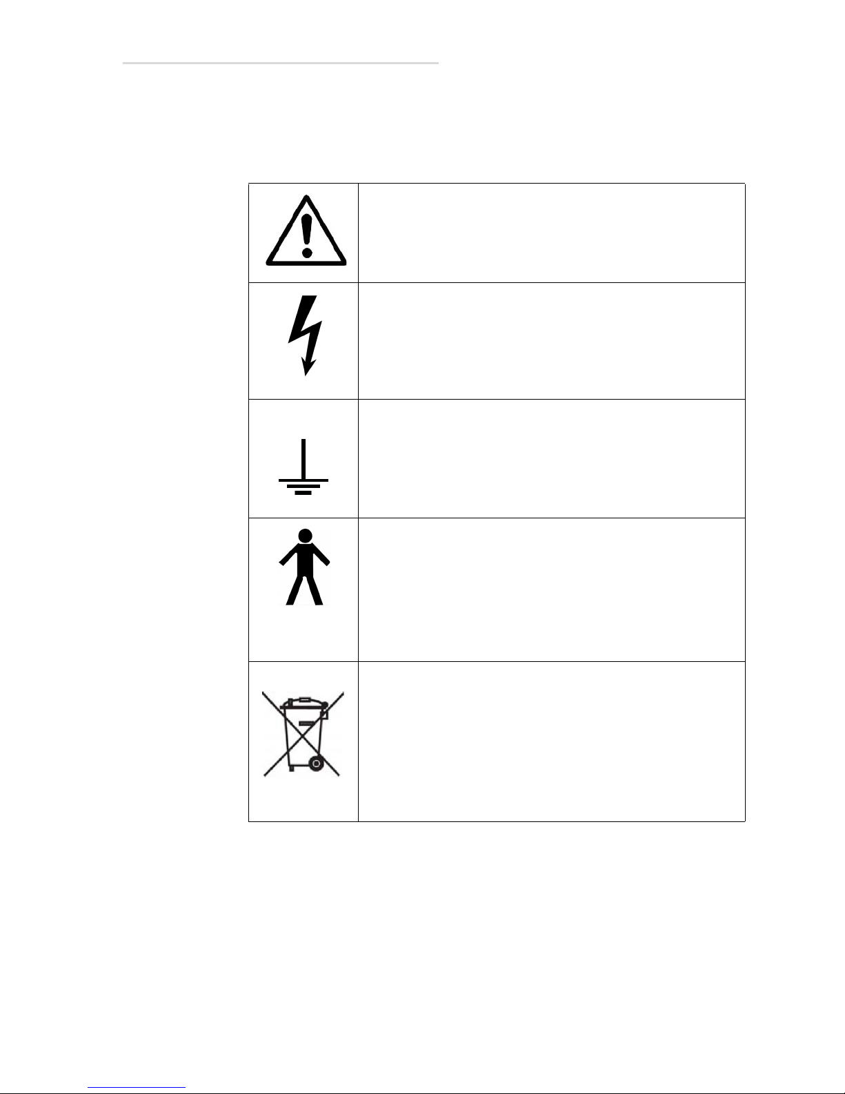
The table below defines the meaning of various symbols found on device
labels on the machine.
This warning symbol indicates a potential hazard to
operators, service personnel or equipment. It indicates a
requirement to refer to the accompanying documentation for
details.
This symbol indicates that there is accessible dangerous
voltage.
This symbol identifies a protective earth terminal or ground.
This symbol states that this product is categorized as Type B.
Type B is defined as:
Equipment providing a particular degree of protection
against electric shock, particularly regarding allowable
leakage currents and reliability of the protective earth
connection (if present).
This symbol indicates that you must dispose of the EV800
Elevating Table properly according to local laws and
regulations. The EV800 contains electronic components;
therefore, it must be disposed of separately from household
waste. When the EV800 reaches its end of life, contact local
authorities to learn about disposal and recycling options.
The table has an estimated life of 10 years from point of
purchase. This may vary depending on (1) product use, (2)
product maintenance, and (3) environmental conditions.
Table 1-1: Definition of symbols found on device labels.
Definitions i-3
Page 10

EV800 Elevating Table Installation, Operation, & Service Manual
Warning
Safety Conventions Used in this Manual
Specific safety information is listed in this manual in the form of
WARNING and CAUTION statements. Pay close attention to these
statements as they contain important information on avoiding potential
hazards to you or the equipment.
Warning Statements:
• Are used to indicate hazards or unsafe practices which COULD result
in severe personal injury or death.
• Appear in bold type.
• Have a triangular symbol with an exclamation point above the text.
• Are preceded by the word Warning.
• Are always found before the step or piece of information to which
they refer.
• Look like the following example:
This text will describe special safety precautions to follow in order
to avoid unsafe practices that COULD result in severe personal
injury or death.
i-4 Safety Conventions Used in this Manual
Page 11
Caution Statements:
Caution
• Are used to indicate hazards or unsafe practices which could result in
minor personal injury or product/property damage.
• Appear in bold type.
• Have a triangular symbol with an exclamation point above the text.
• Are preceded by the word Caution.
• Are always found before the step or piece of information to which
they refer.
• Look like the following example:
This text will describe special safety precautions to follow in order
to avoid unsafe practices that could result in personal injury or
product/property damage.
EV800 Elevating Table Installation, Operation, & Service Manual
Safety Conventions Used in this Manual i-5
Page 12
EV800 Elevating Table Installation, Operation, & Service Manual
Warning
Warning
Equipment Safety Guidelines
The following warnings and cautions are specific to the EV800 Elevating
Table. Read them carefully - some of them are not obvious to typical
equipment use.
Turn off electrical power to the table at the power source before
servicing the table. Also, make sure that the power source is
locked out and tagged “Table Being Serviced” before servicing the
table; you could get seriously shocked or burned if you do not.
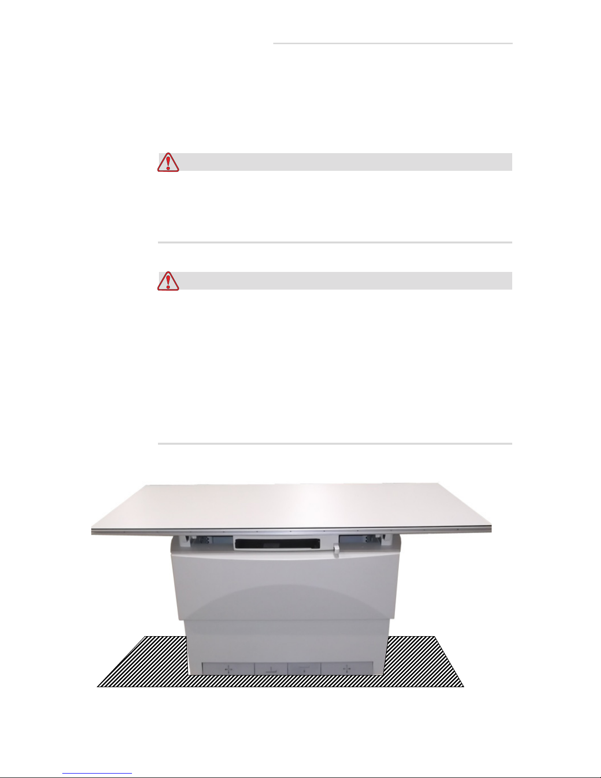
Do not place any objects within the vertical motion area above or
below table. Objects in such areas can present crush hazards for
the patient or operator and can also damage the table. See shaded
areas in figure below.
The table is equipped with a collision avoidance switch for
downward motion. This switch is designed to protect the table top,
not the operator or patient from a collision. The downward motion
of the table will stop if the table encounters 100 lbs (44kgs) of
upward force.
i-6 Equipment Safety Guidelines
Page 13
EV800 Elevating Table Installation, Operation, & Service Manual
Warning
Warning
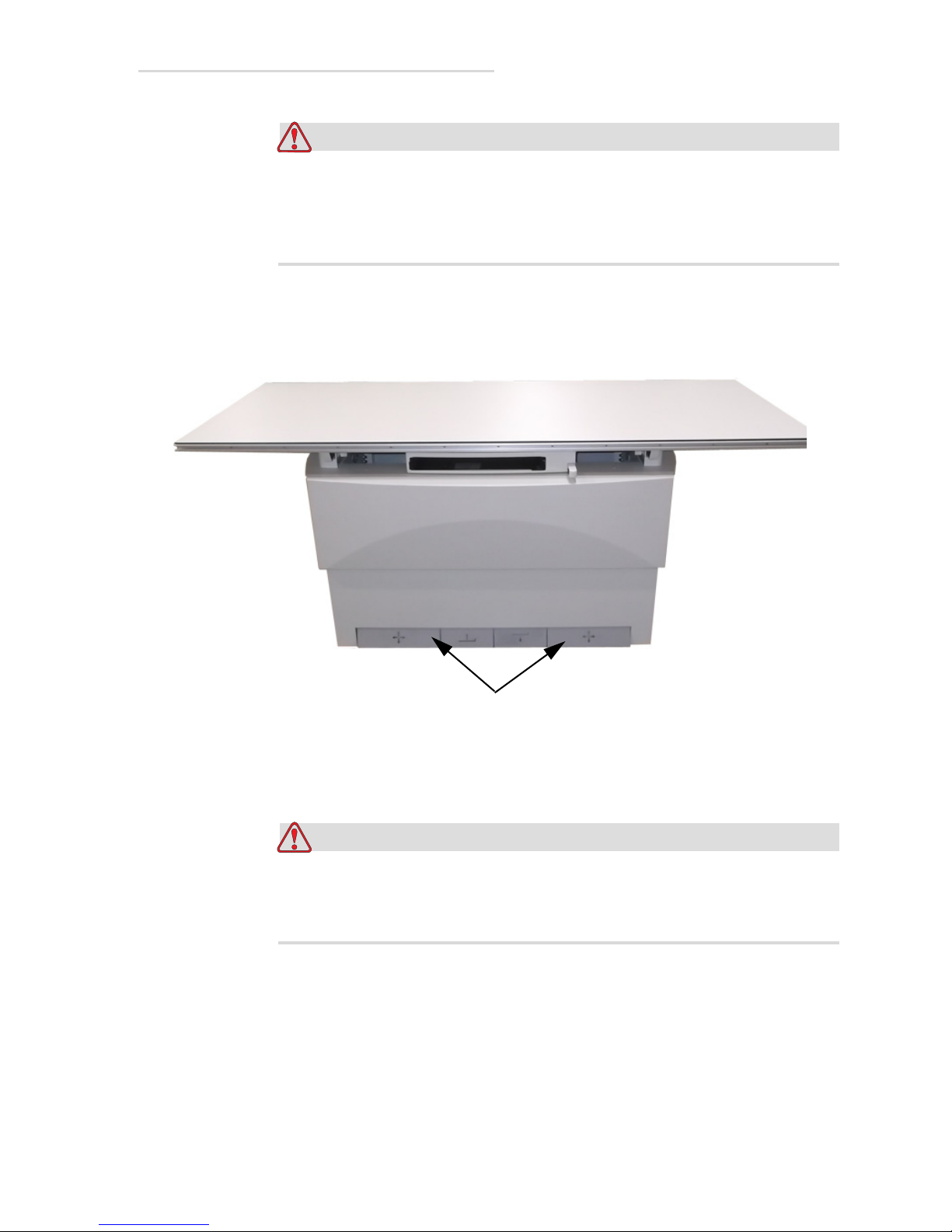
Table Top Lock Release Pedals
Make sure the operator or the patient does not touch the table’s
unlock pedals when the patient is getting on or off table. This may
cause the patient to fall off the table and cause serious injury. See
figure below.
Do not operate the table in an explosive atmosphere (such as
anesthetic gas). Doing so can cause an explosion or a fire hazard
which could cause serious injury.
Equipment Safety Guidelines i-7
Page 14

EV800 Elevating Table Installation, Operation, & Service Manual
Warning
Warning
All of the movable assemblies and parts of this equipment should
be operated with care and routinely inspected in accordance with
the manufacturer’s recommendations contained in this manual.
Only properly trained and qualified personnel should be
permitted access to any internal parts. Live electrical terminals are
deadly; be sure line disconnect switches are opened and other
appropriate precautions are taken before opening access doors,
removing enclosure panels, or attaching accessories.
Do not remove flexible high tension cables from X-ray tube
housing or high-tension generator and/or access covers from X-ray
generator until the main and auxiliary power supplies have been
disconnected.
For all components of the equipment, protective earthing means it
must be provided in compliance with the national regulations.
This table is intended to be used as part of a system for the
intended generation of X-rays for medical diagnosis.
X-rays generate a potential risk for both patients and operators.
For this reason, the application of X-rays for a given medical
purpose must aim at the minimization of radiation exposition to
any persons.
Those persons responsible for the application must have the
specific knowledge according to legal requirements and
regulations and must establish safe exposure procedures for this
kind of system.
Those persons responsible for the planning and installation of this
equipment must observe the national regulations.
i-8 Equipment Safety Guidelines
Page 15
EV800 Elevating Table Installation, Operation, & Service Manual
Warning
Emergency Stop Button
Emergency Stop Button (For Service Technicians
Only)
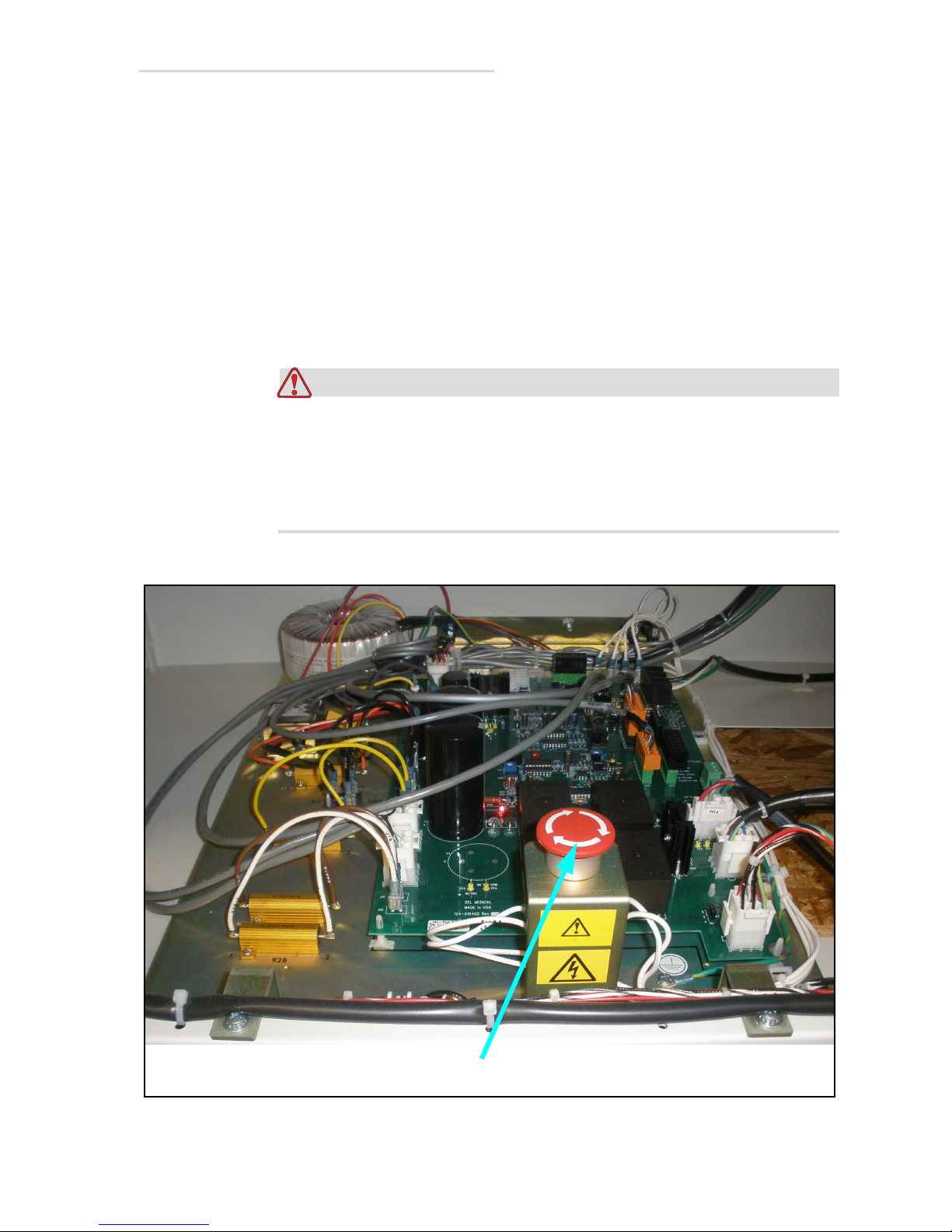
There is an Emergency Stop button located in the table’s base that can be
pressed to stop the motion of the table in an emergency. It is meant only to
be used by technicians who are troubleshooting the table.
If the button is pressed, it must be turned in the direction of the arrows on
the button until the button pops back up in order to reset the button.
Otherwise, the table cannot be restarted. See Figure below for location of
button.
The Emergency Stop button DOES NOT turn off all power to the
table. There may still be lethal voltages present on the main
chassis and throughout the table when this button is turned off.
These voltages come from sources outside the table (i.e. generator,
wallstand, etc.) that are connected to the table.
Emergency Stop Button
Emergency Stop Button (For Service Technicians Only) i-9
Page 16
EV800 Elevating Table Installation, Operation, & Service Manual
Warning
LED must be off before servicing table.
Electrical Discharge (For Service Technicians Only)
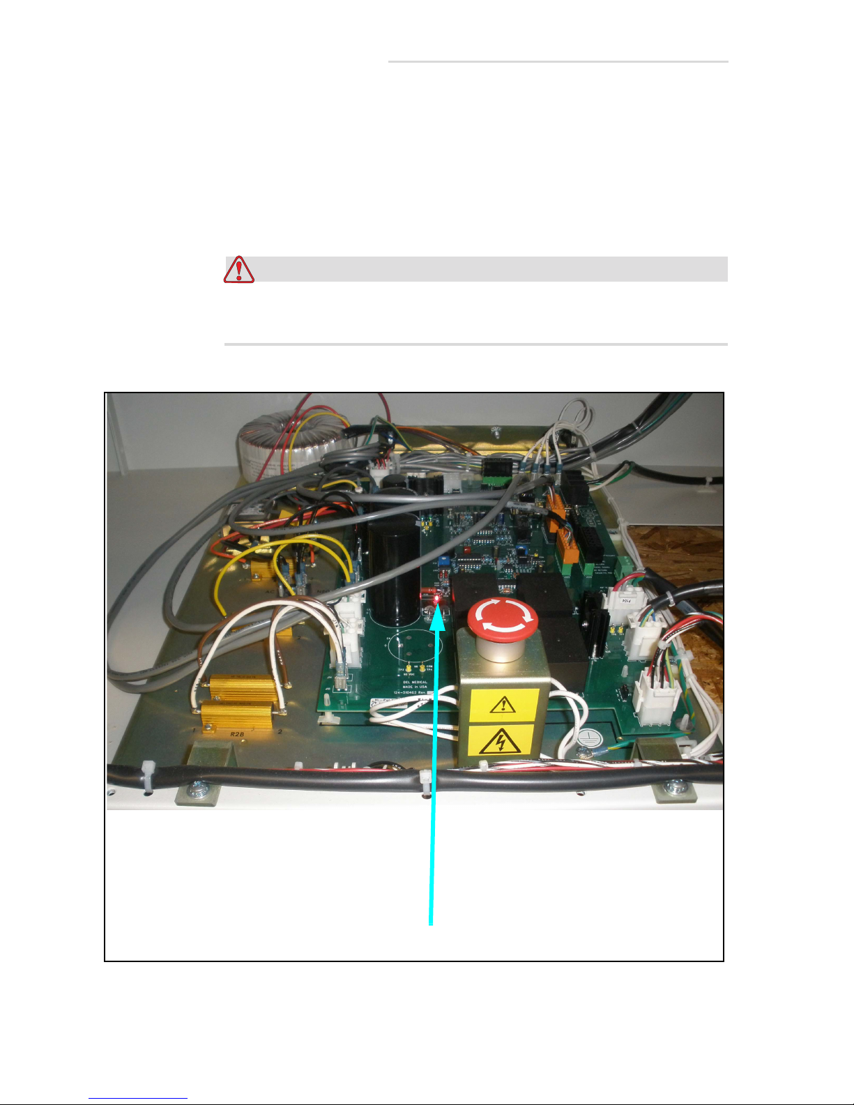
This table’s main PCB contains capacitors that store energy after the
machine is turned off. You can be severely shocked if you work on the
table before these capacitors have completely discharged. The LED next to
the capacitors must be off before you can work on the machine. When the
LED is off, the capacitors have completely discharged.
Do not work on the table before the capacitor’s LED is off; you can
be severely shocked if you do.
i-10 Electrical Discharge (For Service Technicians Only)
Capacitor Discharge LED
Page 17
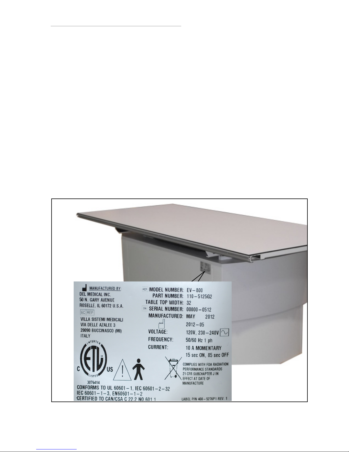
Identification Labels
The EV800 components have manufacturing and certification information
affixed. The manufacturing label contains:
• The full name and address of the manufacturer of the component
• The place, month, and year of manufacture
• The model number and serial number of the component
The certification label also states that the component complies with either
“21CFR, Subchapter J”or the applicable DHHS standards under the
Radiation Control for Health and Safety Act of 1968 (or its equivalent).
A label may combine both manufacturing and certification information.
The underside of the removable float-top also has a label with matching
serial number and date of manufacturing.
EV800 Label
The location of the EV800 identification label is shown in Figure i-1.
EV800 Elevating Table Installation, Operation, & Service Manual
EV800 Identification Label
Identification Labels i-11
Page 18

EV800 Elevating Table Installation, Operation, & Service Manual
Product Life
The table has an estimated life of 10 years from the point of purchase. This
may vary depending on the (1) product use, (2) product maintenance, and
(3) environmental conditions. When it has been determined that the table
has completed its useful service life, local regulations must be complied
with in regards to the proper disposal of the possible hazardous materials
used in the manufacturing of the table.
The table contains electronic components, such as: soldered (may contain
lead) circuit boards, tinned copper wire, transistors, diodes, resistors,
capacitors, etc. The cabinet is made from steel and/or aluminum.
NOTE
DO NOT INCINERATE THIS PRODUCT. DO NOT PUT IN TRASH
THAT IS DISPOSED OF IN LANDFILLS. DISPOSAL OF THIS
PRODUCT MUST ADHERE TO LOCAL ORDANANCES AND
REGULATIONS. LOCAL AUTORITIES MUST BE CONTACTED FOR
PROPER DISPOSAL AND/OR RECYCLING OPTIONS FOR ALL OF
THE COMPONENTS LISTED ABOVE.
i-12 Product Life
Page 19
Record of Revisions
2.1 Revision History
REV Date Reason for Change
A1-2-2012Original
Table ii-1. Revision History
ii
Revision History ii-1
Page 20

EV-800 Elevating Table Installation, Operation & Service Manual
2.2 List of Affected Pages
Page Number Rev
Level
All A
Table ii-2. List of Affected Pages
Page Number Rev
Level
Page Number Rev
Level
ii-2 List of Affected Pages
Page 21

Introduction
1.1 Introduction
This manual provides installation, operation, and service information for
the EV800 Elevating Table. This manual also includes a spare parts list for
the table.
1
Introduction 1-1
Page 22

EV800 Elevating Table Installation, Operation, & Service Manual
1.2 Description
The EV800 elevating radiographic table is designed for general purpose
radiography and is ideally suited for modern hospitals, urgent care
centers, clinics, and private practices.
The EV800 features a four-way, floating table top which provides 41” (104
cm) of longitudinal travel and 9.25” (23.5 cm) of transverse travel (13.25”
(33.7 cm), with 36” wide table top option. It has a motor driven telescopic
base which permits the tabletop to be lowered to within 22” (55.9 cm) of
the floor and raised to a maximum height of 34” (86.4 cm) above the floor.
Electro-mechanical locks maintain the desired position. The position of the
table top can be raised and lowered, and the locks released and engaged
by operating the two outside foot pedals. The table’s bucky can also be
repositioned by pressing the pushbutton.
1-2 Description
Page 23
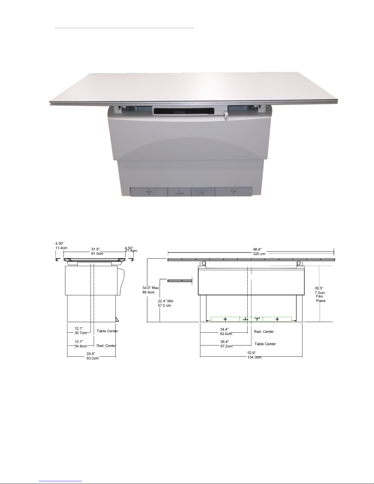
1.3 Dimensions
EV800 Elevating Table Installation, Operation, & Service Manual
Figure 1-1. Dimensions
Dimensions 1-3
Page 24
EV800 Elevating Table Installation, Operation, & Service Manual
Caution
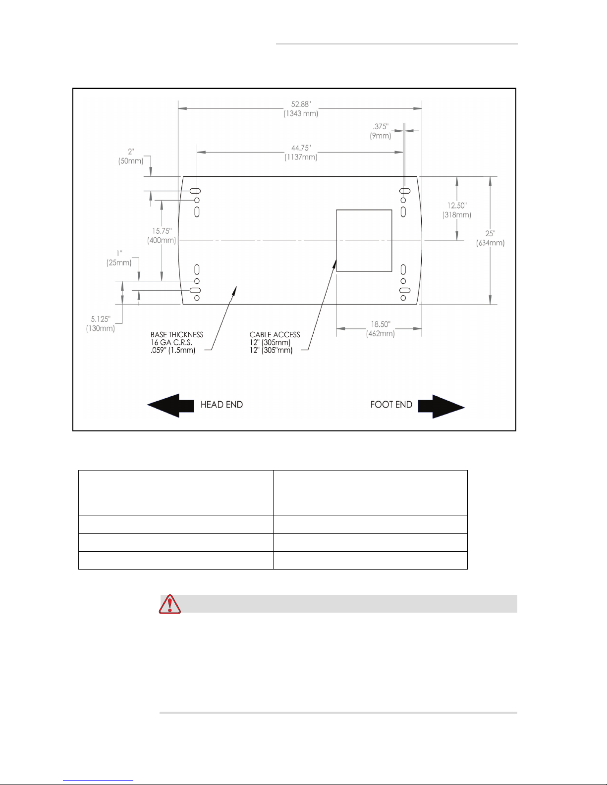
Figure 1-2. Table Foot Print
Note: Bolt hole locations and overall base
dimensions are symmetrical unless
otherwise dimensioned.
Total Area of Base 8.8 Sq./Ft. (.818 Sq. M)
Floor Loading 56.8 Lbs/Sq. Ft. (277.5 Kg/Sq. M)
Bolt Hole Diameter .75” (19mm) 4 Locations
Do not drill equipment mounting holes in pre-tensioned or post
tensioned concrete floors before determining the location of the
tensioned wire ropes. Consult with customer or responsible
project engineer to locate and avoid drilling through wire rope.
Cutting through tensioning cables can cause severe structural
damage.
1-4 Dimensions
Page 25
EV800 Elevating Table Installation, Operation, & Service Manual
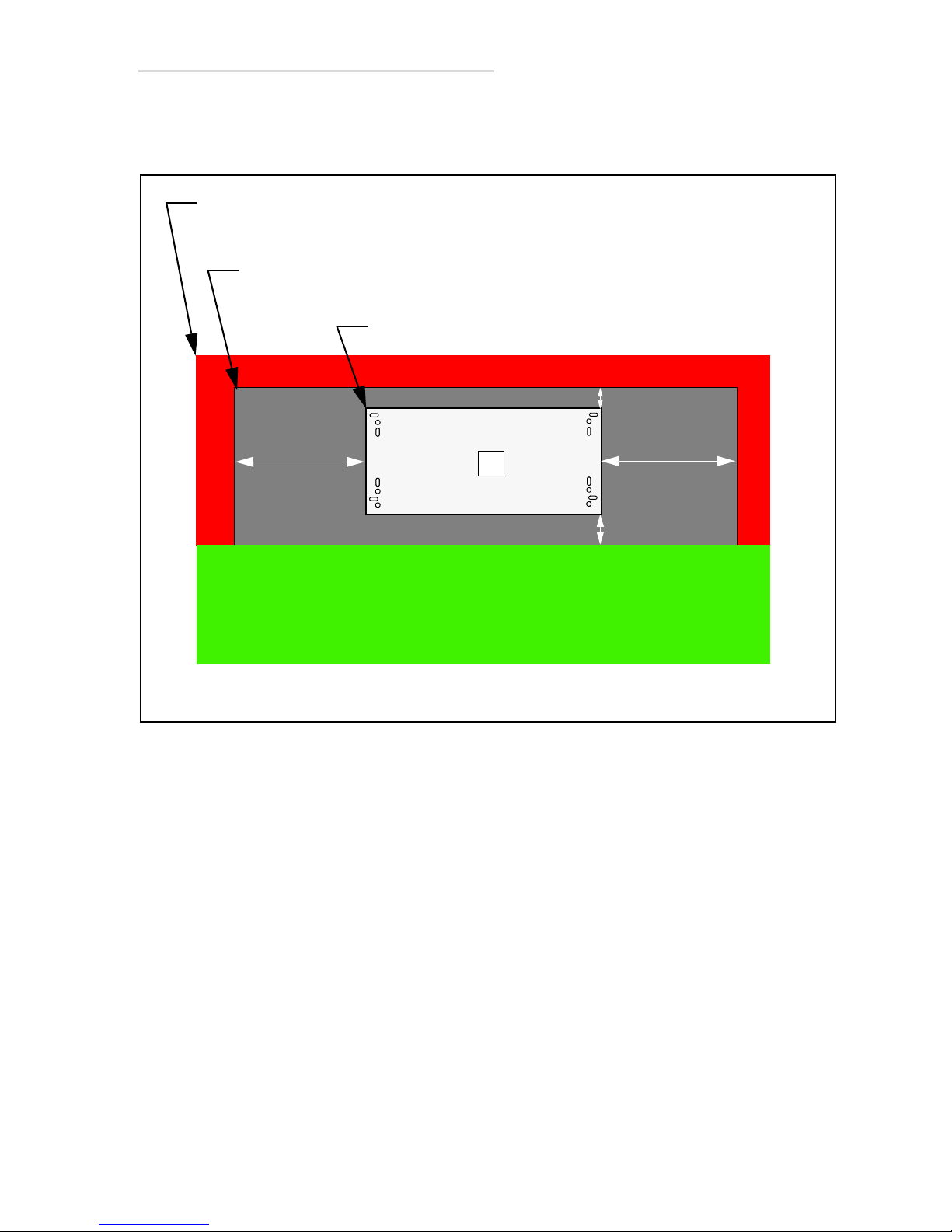
Front
Minimum 12” (30 cm) Side & Rear Hazard-Free
Table Top Range of Motion - 125” X 40” (317 cm X 102cm)
Table Base - 52 7/8” X 25” (134.4 cm X 63.4 cm)
Frontal space requirements are
site specific based on clinical
needs (i.e. wheel chair, gurney
accessibility requirements).
Buffer Zone Required Beyond Table Range -137” X 52” (348 cm X 132 cm)
40” (102 cm)
40” (102 cm)
9” (23 cm)
6” (15 cm)
1.4 Minimum Space Requirements
Figure 1-3. Plan View (Top View) of Minimum Space Requirements
Minimum Space Requirements 1-5
Page 26
EV800 Elevating Table Installation, Operation, & Service Manual
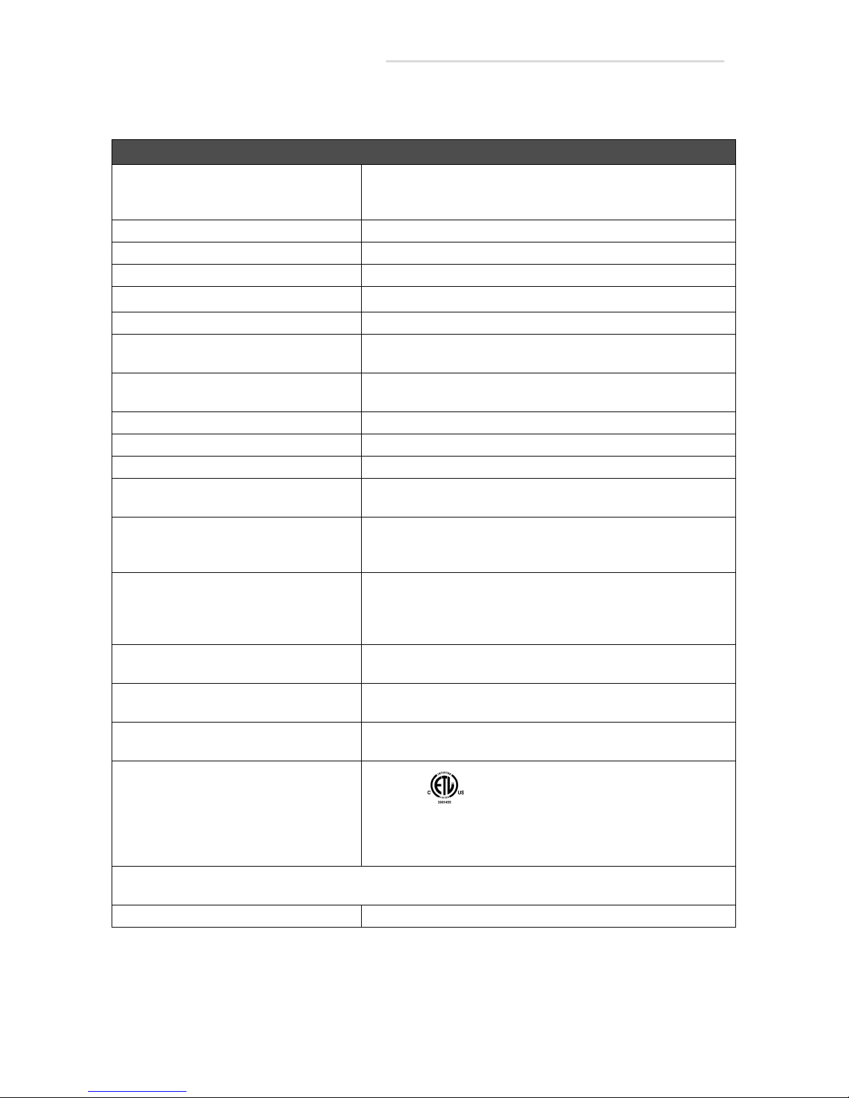
1.5 Specifications
Specifications
Compatibility The EV800 Elevating Table is compatible with a wide variety of
generators, wallstands, and tubestands. It is intended to be used
in a stationary diagnostic X-ray configuration.
Voltage 120VAC or 230/240 VAC
Current 10 Amps, Momentary 15 sec ON, 85 sec OFF
Frequency 50/60 Hz Single Phase
Incoming Power Line
External Heat Generation 300 Btu (88 watts)
Fuse Type Line (FL1) & (FL2) 10 Amp
Classification Class 1 Type B
Patient Lift Limit 800 lbs (363Kg)
Duty Continuous
Mode of Operation Momentary
Aluminum Equivalent Beam Attenuation of the Standard Table Top is 0.7 mm Alumi-
Temperature Limits Transit/Storage Operating
Relative Humidity Limits Transit/Storage
Atmospheric Limits 14.5 inHg to 30.74 inHg
Weight Table Base: 473 lbs (210 Kg)
Degree of protection against the ingress
of water:
Certifications:
3 #16 AWG (1.5mm
Motor (F1) 10 A
num Equivalent or Less
– 40° F to +158° F +50° F to +95° F
– 40° C to +70° C +10° C to +35° C
10% to 100%
Operating
10%-80% Non-Condensing
500 hPa to 1060 hPA
Table Top: 77 lbs (34Kg)
Ordinary
2
) for 50ft (15.25M) or Less
Equipment not suitable for use in the presence of flammable anesthetic mixtures with air, oxygen or nitrous
oxide.
No user serviceable parts
1-6 Specifications
Classified To UL 60601-1,IEC60601-1, EN60601-1, IEC
60601-2-32, EN60601-2-32, IEC60601-1-3, EN60601-1-3.
Certified To CAN/CSA C22.2 NO. 601.1.
Table 1-1: Specifications
Page 27

1.6 Abbreviations
%Percent
AWG American Wire Gauge
Btu British Thermal Unit
° C Degree Celsius
CE Communautés Européennes
cm Centimeter
C.R.S. Cold Rolled Steel
° F Degree Fahrenheit
ga Gauge
hPa Hecto Pascal
inHg Inches Mercury
EV800 Elevating Table Installation, Operation, & Service Manual
Kg Kilogram
Lb Pound
MMeter
max. Maximum
min. Minimum
mm Millimeter
PBL Positive Beam Limitation
Sq/Ft Square Foot
Sq/M Square Meter
UL Underwriters Laboratories
Abbreviations 1-7
Page 28
EV800 Elevating Table Installation, Operation, & Service Manual
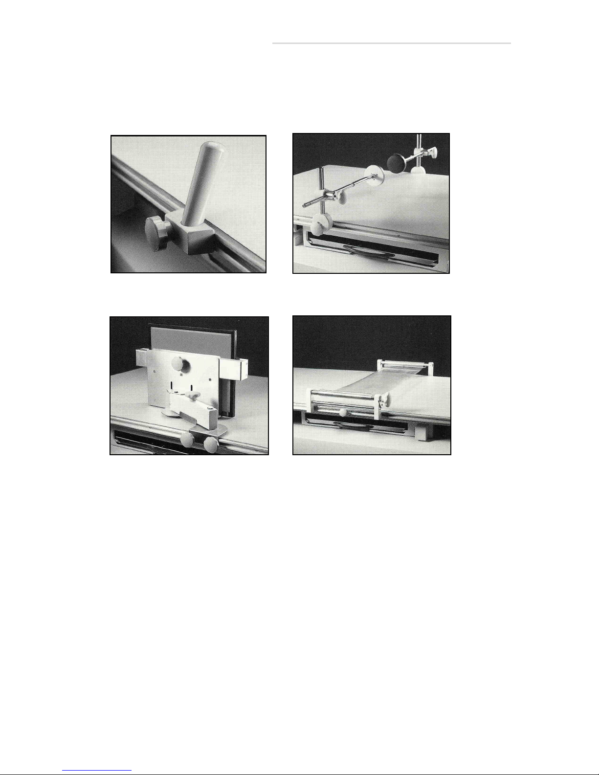
Hand Grips
Compression Band
Lateral Cassette Holder
Head Clamps
1.7 Optional-Accessories
See page 9-36 for Part ID for accessories.
1-8 Optional-Accessories
Page 29
Installation
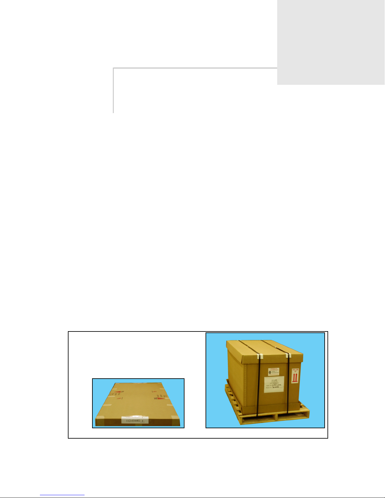
Table Top Shipping Box Base Shipping Box
2.1 Installation Instructions
Tools Required:
• Diagonal cutters (side cutters)
• Medium phillips screwdriver
• Pallet hoist
• Power drill and masonry bit (size determined by installer)
• Scale for measuring downward force of up to 120 lbs (53 Kg.)
2
• Set of hex wrenches
• Set of nut drivers
• Set of open-end wrenches
• Small flat-tip screwdriver
• Utility knife
Note: Two people are required to perform this installation procedure.
Your shipment will arrive in two boxes as shown below. One box will
contain the table top and the other box will contain the base. Save the
boxes until the table is inspected for shipping damage and is up and
operating.
Figure 2-1. Shipping Boxes
2.1 Installation Instructions 2-1
Page 30
EV800 Elevating Table Installation, Operation, & Service Manual
2
1
1
2
3
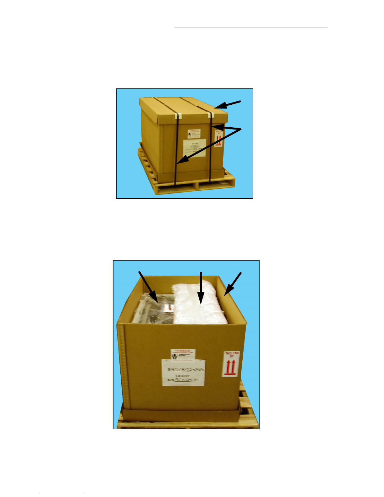
1 Move the base pallet to the approximate position where the base will
be installed.
2 Use diagonal cutters to cut the steel straps (1 in Figure 2-2). Remove
the straps and the top cover (2).
Figure 2-2. Steel Shipping Straps
3 Remove the front cover (1 in Figure 2-3) from the box and unwrap it.
4 Lift off outer box shell (2).
5 Remove the shrink wrapping (3) from around the base.
Figure 2-3. Unpack Box
2-2 2.1 Installation Instructions
Page 31
EV800 Elevating Table Installation, Operation, & Service Manual
1
3
1
2
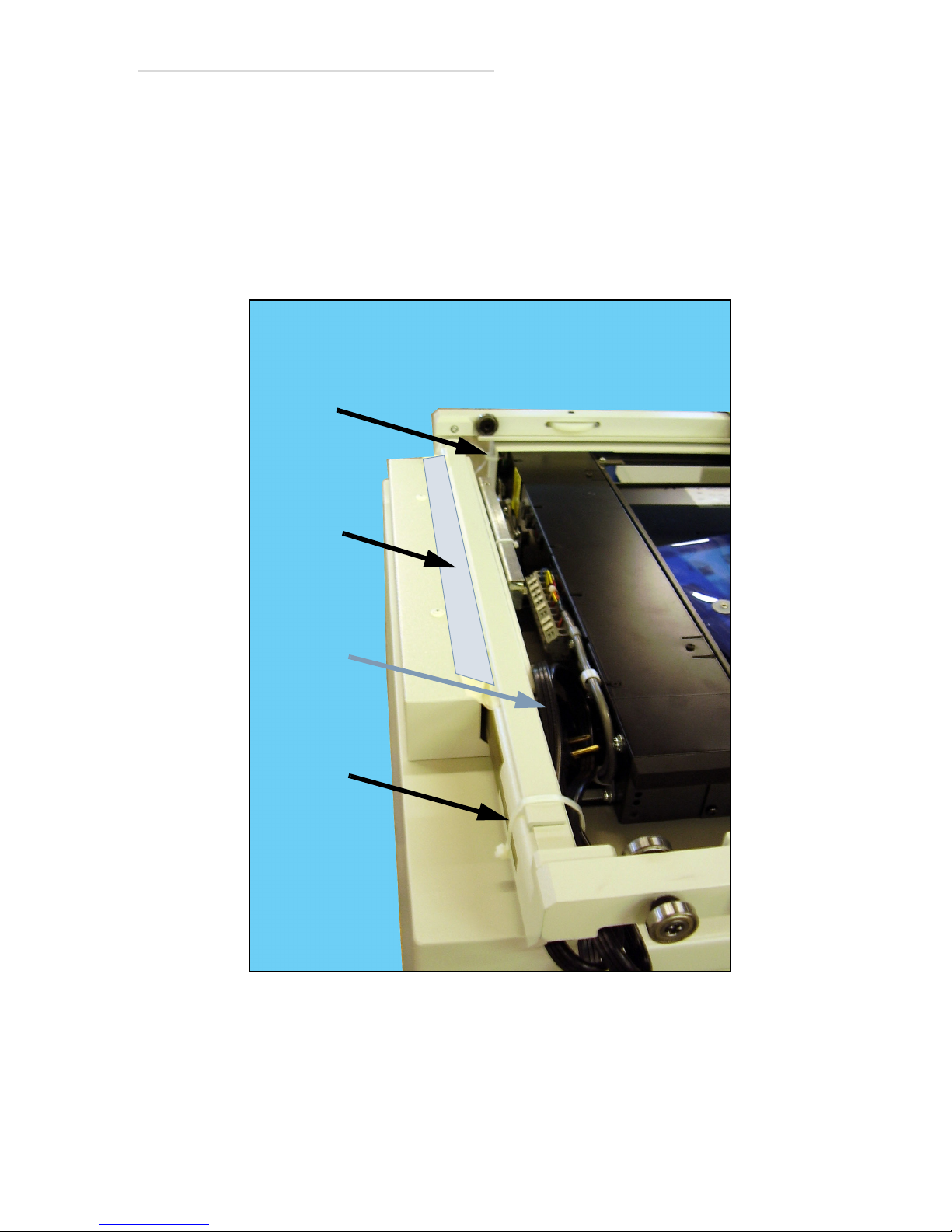
6 Cut and remove the tie wraps (1 in Figure 2-4).
7 Peel off tape (2) on both ends of the base. Only one end is shown in
Figure 2-4.
8 Pull the power cord (3) from the base and unwrap it.
9 Plug in the table’s power cord.
Figure 2-4. Removing Restraints
2.1 Installation Instructions 2-3
Page 32
EV800 Elevating Table Installation, Operation, & Service Manual
Warning
Up Pedal
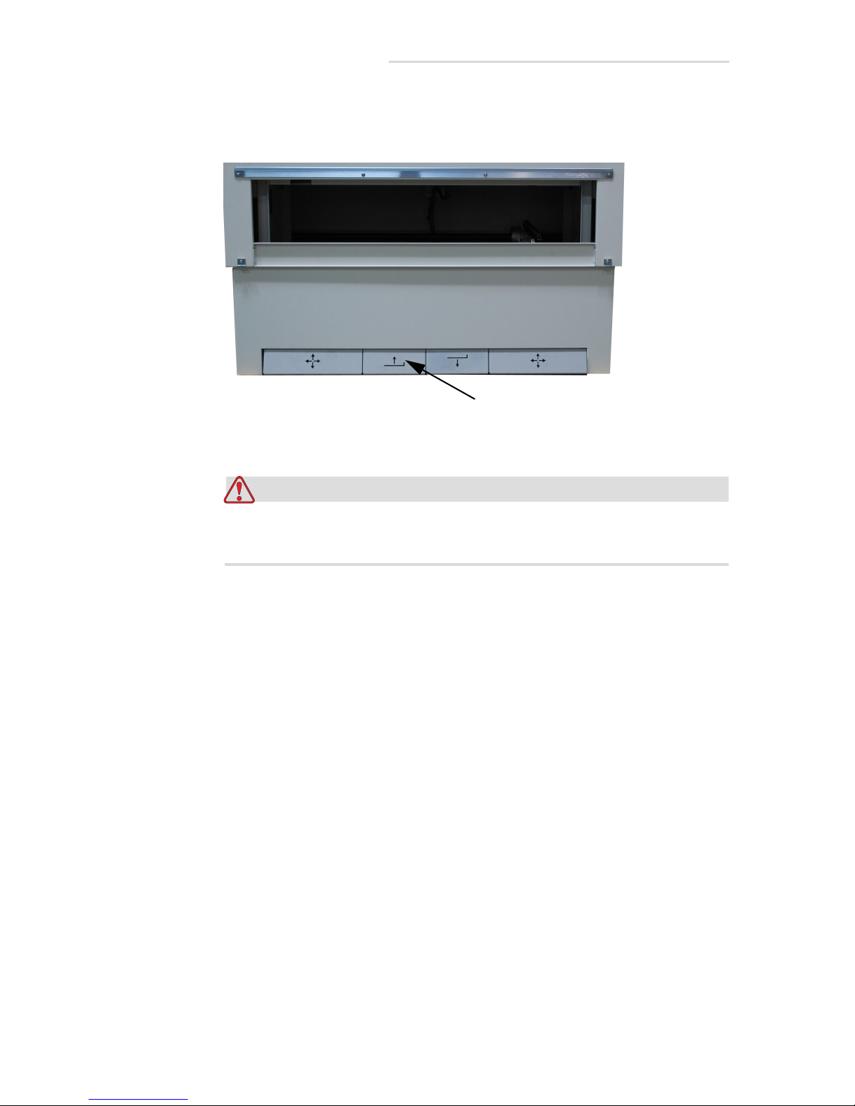
10 Press and hold the Up pedal (1 in Figure 2-5) until the base rises to its
mid-level position where it will stop. Press and hold the Up pedal
again until the base rises to its highest position where it will stop.
Figure 2-5. Up Pedal
Unplug the base’s power cord before performing the following
steps. You could get seriously injured if you do not.
11 Unplug the power cord.
2-4 2.1 Installation Instructions
Page 33
1
3
4
2
EV800 Elevating Table Installation, Operation, & Service Manual
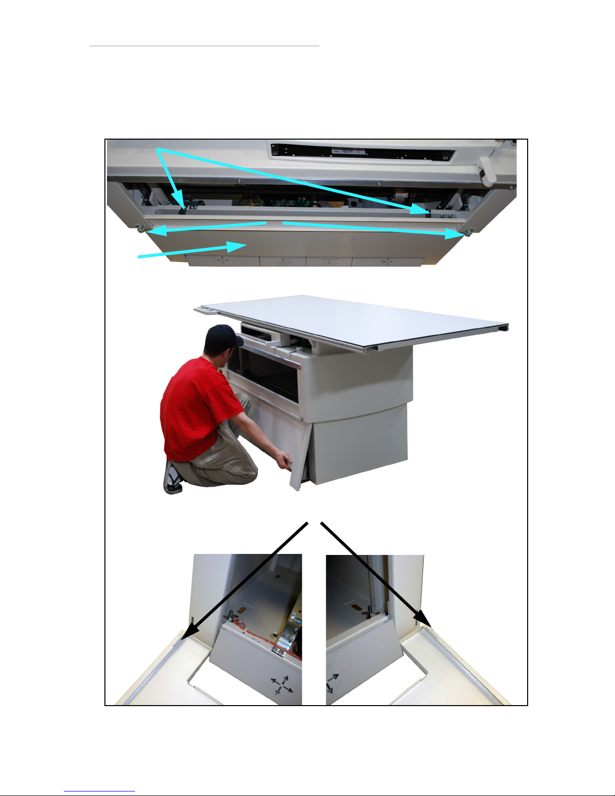
12 Unscrew the two lower panel clamp screws (1 in Figure 2-6), then
remove the lower panhead screws (2).
13 Lift the lower panel (3) up slightly and then pull it out. The bottom of
the lower panel is connected to the table by slots (4) shown below.
Figure 2-6. Lower Panel Clamps
2.1 Installation Instructions 2-5
Page 34
EV800 Elevating Table Installation, Operation, & Service Manual
Caution
Warning
Caution
Caution
Use extreme care when moving the base off the pallet and not to
damage the foot pedals. Do not pry on the pedals or let the pedals
rest on the edge of the pallet when moving the base.
14 Lift the base off the pallet and place the base in its final resting
position.
You must use four 1/2’-13 x 3” (M12 X 75mm) bolts and appropriate
anchors and washers to mount table base to floor. Use of any size
smaller may cause the table base to break free from the floor under
extreme load and leverage conditions. This condition could cause
severe injury to the patient and/or user.
It is up to the installer and the customer to determine the best
method for mounting the base to the floor. Before mounting the
base, consult with the building’s maintenance supervisor about
drilling holes in the floor. Make sure that there are no hazards
under the floor such as pipes, conduits, or structural cables that
can be damaged by drilling holes in the floor.
Do not mount the table base to the floor until the tubestand or
overhead tube crane that accompanies it has been mounted and
aligned correctly; you may have to reposition the table if you do.
15 Mount the base to floor using holes through bottom of the base. There
are several sets of holes that allow some adjustability in positioning
the base. Choose the set of holes that best suits your needs, and then
make sure that base is level after mounting. If necessary, use shims
from accessory kit to aid leveling.
2-6 2.1 Installation Instructions
Page 35
EV800 Elevating Table Installation, Operation, & Service Manual
1
2
PBL Option Installation
16 If your table does not have a PBL (Positive Beam Limitation) option,
go to step 28. If it does have a PBL option, do the following steps.
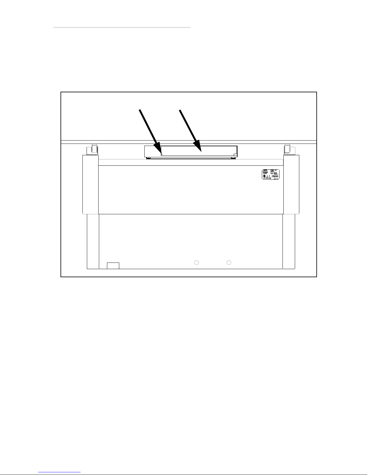
17 Unscrew the bucky rear cover screw (1 in Figure 2-7) and remove rear
cover (2).
Figure 2-7. Bucky Rear Cover
2.1 Installation Instructions 2-7
Page 36
EV800 Elevating Table Installation, Operation, & Service Manual
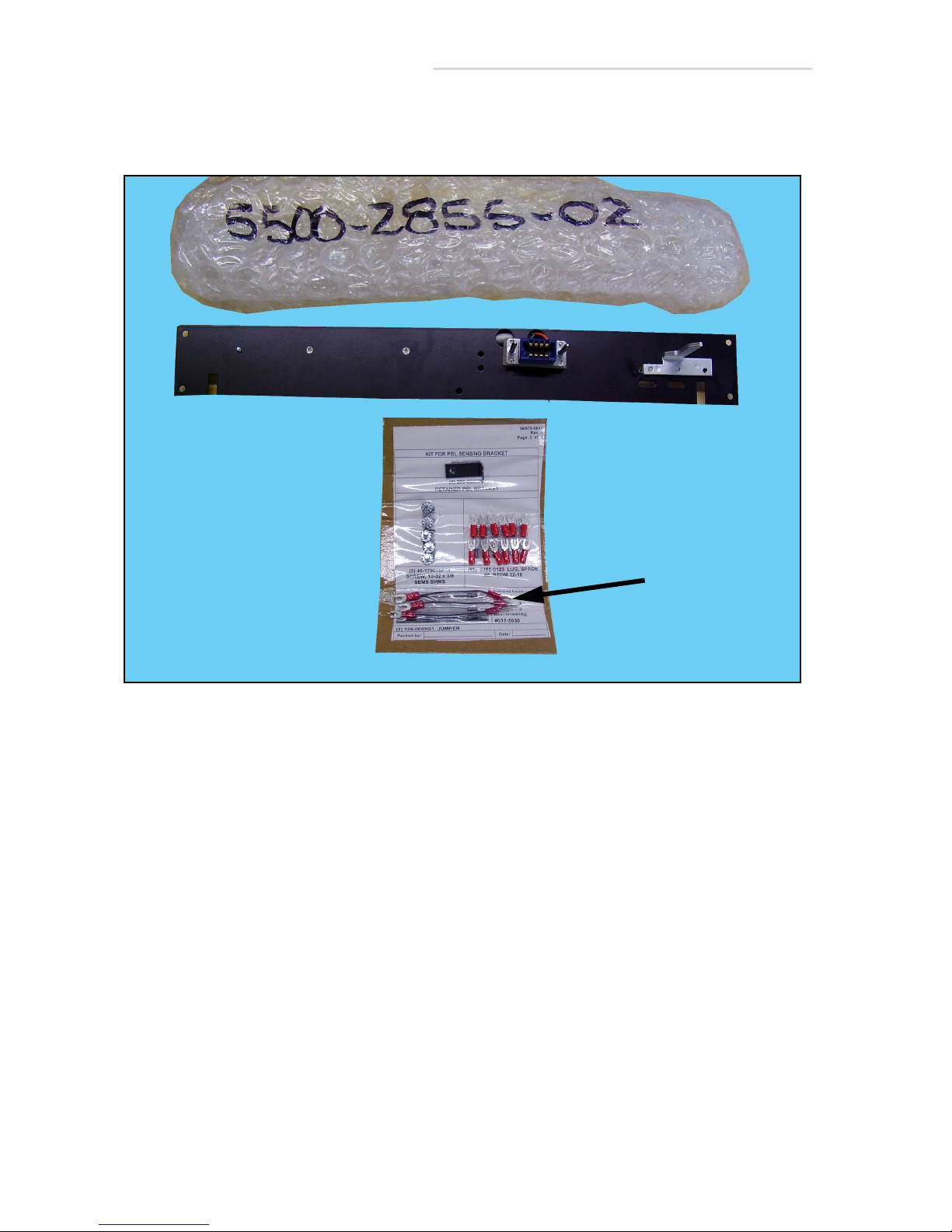
Jumpers
18 Unpack the PBL kit.
Figure 2-8. PBL Kit (Typical)
2-8 2.1 Installation Instructions
Page 37
EV800 Elevating Table Installation, Operation, & Service Manual
1
2 (x4)
3
4
1
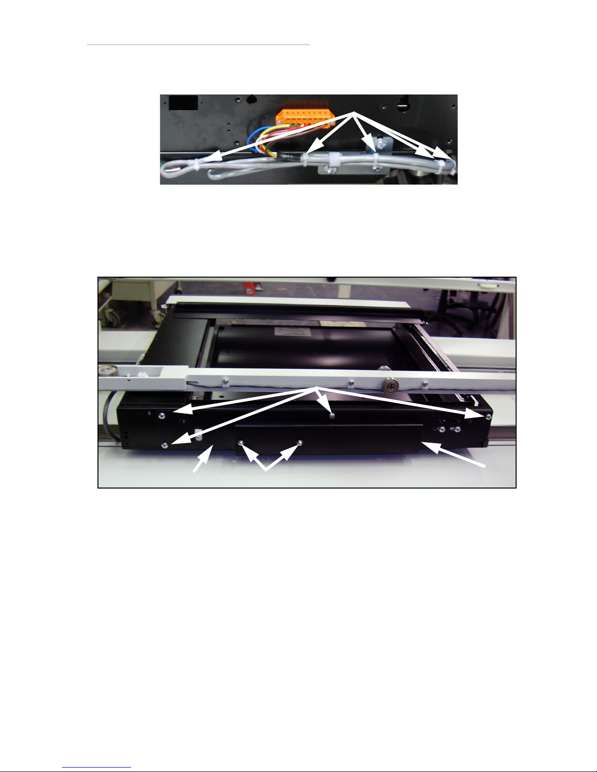
19 Cut tie wraps (1 in Figure 2-9) off the cable.
Figure 2-9. PBL Cable
20 Install the PBL plate assembly (1 in Figure 2-10) on the bucky and
secure it in place with four mounting screws (2).
21 Unscrew the two acorn nuts (3) and remove the cover (4).
Figure 2-10. PBL Plate Assembly
2.1 Installation Instructions 2-9
Page 38
EV800 Elevating Table Installation, Operation, & Service Manual
3
1 & 2
4
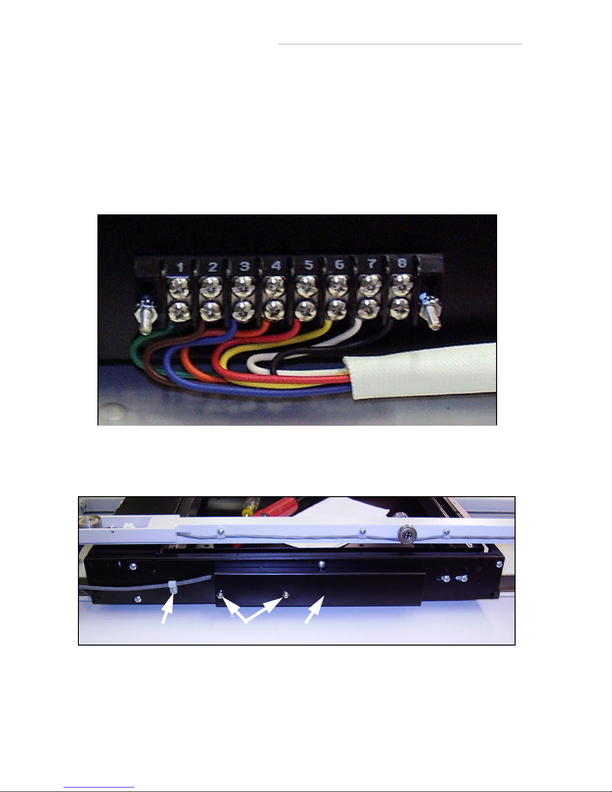
22 Remove three wire jumpers from the PBL kit.
23 Install the jumpers across terminals 1 and 4, 2 and 3, 3 and 6. See
figure below for terminal locations.
24 Connect the PBL cable to the terminal block as follows:
Wht - 4
Grn - 5
Blk - 7
Red - 8
Tape all unused wires with electrical tape.
Figure 2-11. Terminal Block
25 Secure the internal cable with p-clamp & screw (1 & 2 in Figure 2-12).
26 Reattach the cover (3) with two nuts (4).
Figure 2-12. Clamp & Cover
2-10 2.1 Installation Instructions
Page 39
EV800 Elevating Table Installation, Operation, & Service Manual
1
2
Ion Chamber Option Installation
27 If your table does not have a ion chamber option, go to step 42. If it
does have a ion chamber option, do the following steps:
28 Unpack the ion chamber kit.
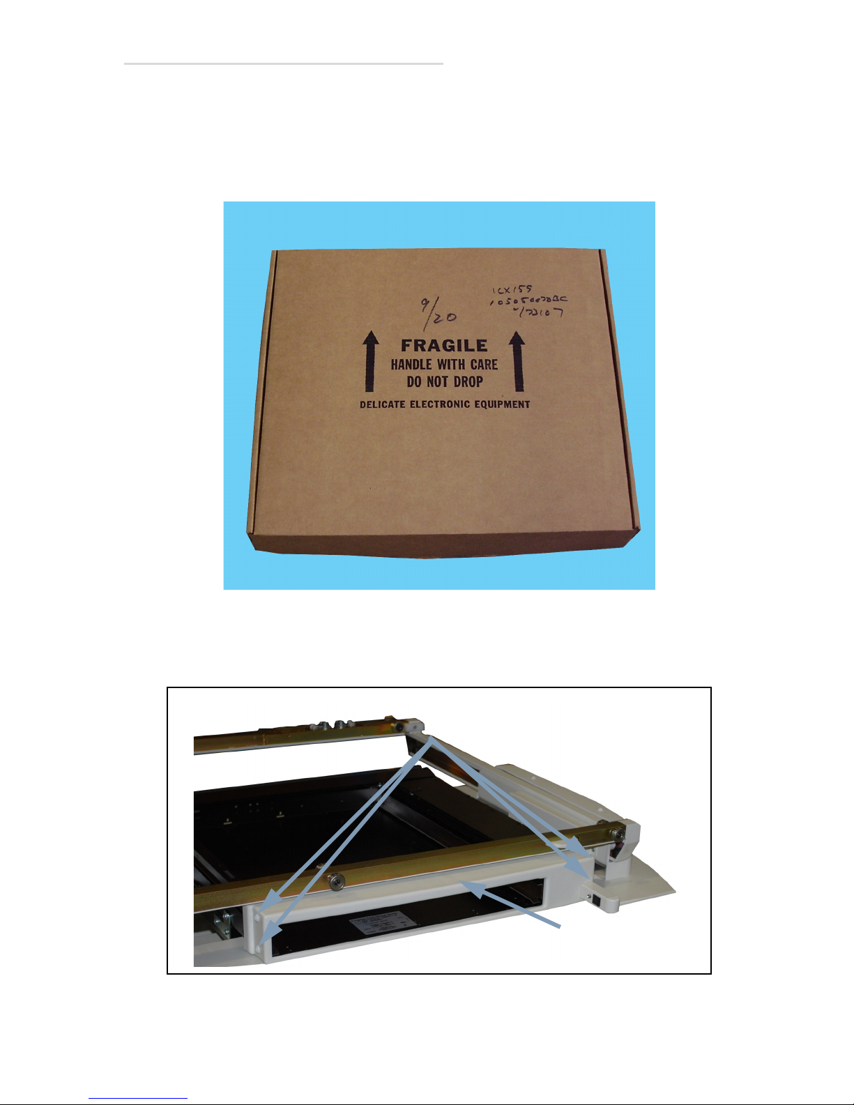
Figure 2-13. Ion Chamber Kit Box (Typical)
29 Unscrew the four cover screws (2 on each side) (1 in Figure 2-14) and
remove the top cover (2).
Figure 2-14. Bucky Top Covers
2.1 Installation Instructions 2-11
Page 40
EV800 Elevating Table Installation, Operation, & Service Manual
2 (x2)
1
3
3
2
1 (x4)
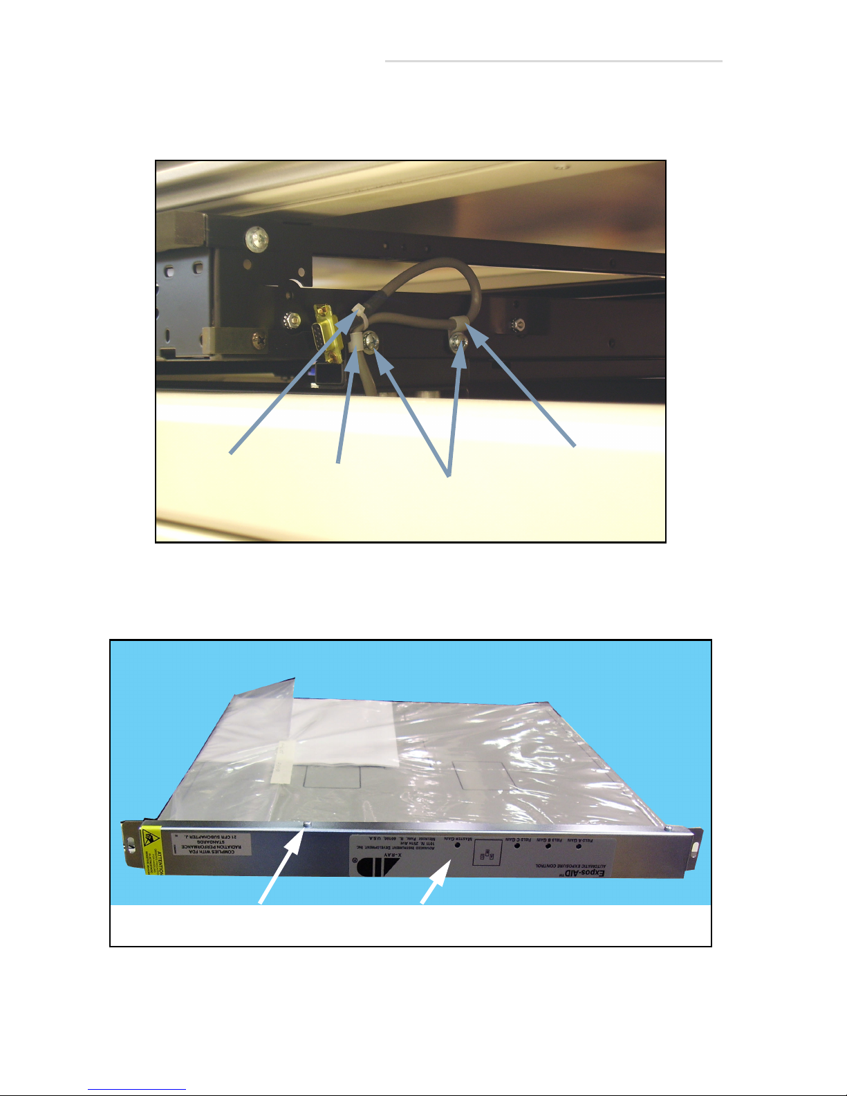
30 Cut the cable tie (1 in Figure 2-15).
31 Unscrew the clamp screws (2) and remove the clamps (3).
Figure 2-15. ION Cable Clamps
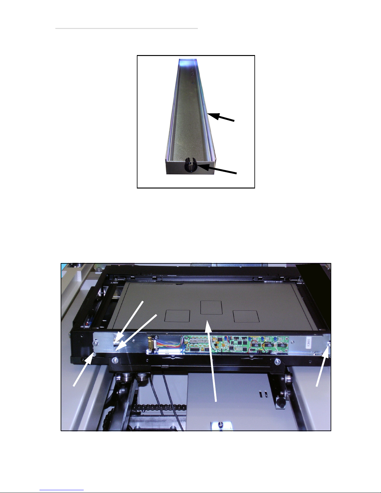
32 Unscrew the four cover screws (1 in Figure 2-16) and remove the
cover (2).
Figure 2-16. Ion Chamber Cover
2-12 2.1 Installation Instructions
Page 41
EV800 Elevating Table Installation, Operation, & Service Manual
1
2
1
2
2
3(x2)
4
33 Remove the grommet (1 in Figure 2-17) from the cover (2).
Figure 2-17. Cover Grommet
34 Adjustments are needed to install the ion chamber assembly (1 in
Figure 2-18). When mounting the ion chamber, the ion chamber needs
to hit the slotting mounting holes. If the ion chamber is screwed down
and hits the grid, then lower the ion chamber, but if it is too low then it
will hit the cassette tray. Check before final tightening of mounting
screws (2). Unscrew the two clamp nuts (3) and remove the clamp (4).
Figure 2-18. Installing Ion Chamber
2.1 Installation Instructions 2-13
Page 42
EV800 Elevating Table Installation, Operation, & Service Manual
5
4
3
2
1
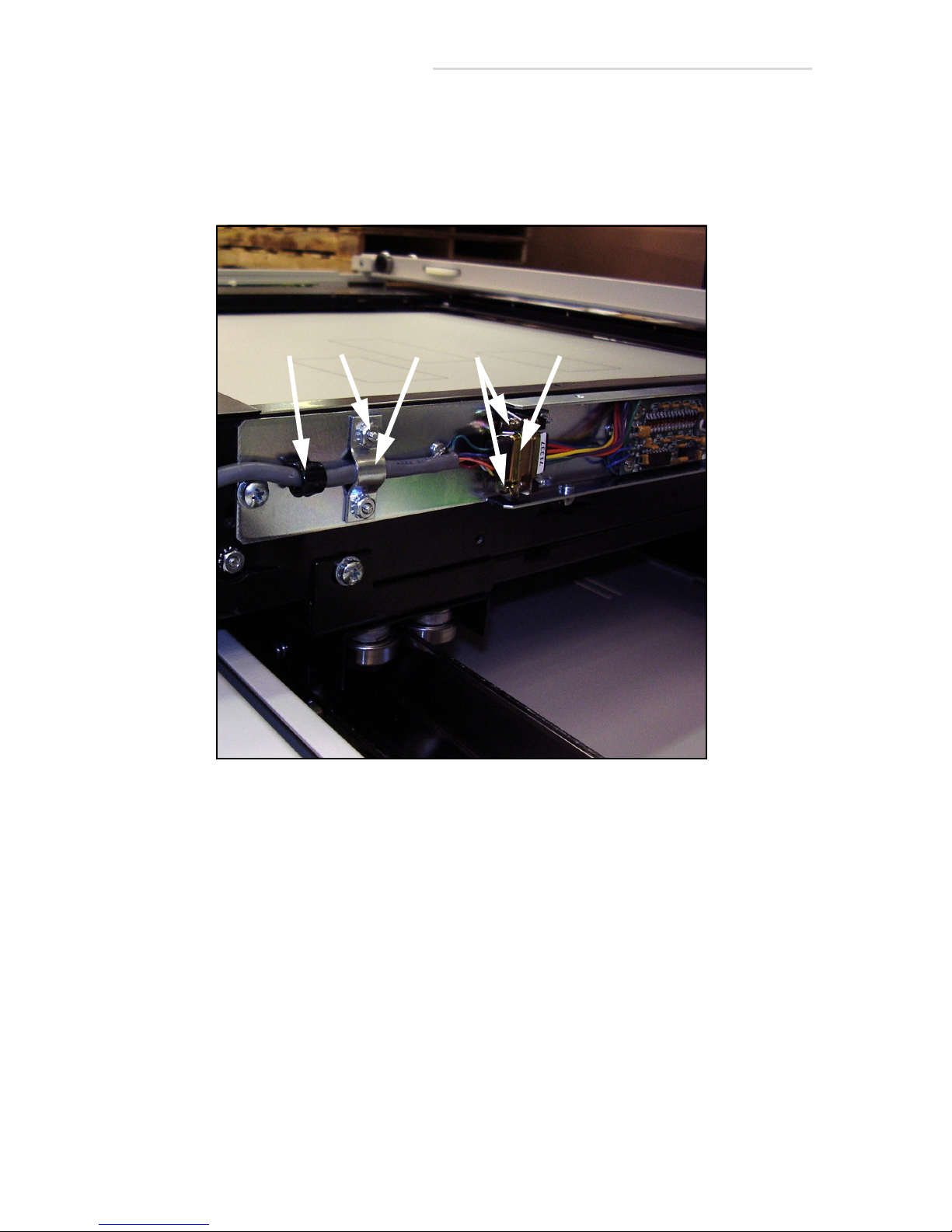
35 Connect the internal ion chamber cable (1 in Figure 2-19) to the ion
chamber and secure with the two mounting screws (2).
36 Install the clamp (3) over the cable and secure with the two nuts (4).
37 Insert the grommet (5) over the cable.
Figure 2-19. Ion Chamber Cable
2-14 2.1 Installation Instructions
Page 43
EV800 Elevating Table Installation, Operation, & Service Manual
2 (x4)
1
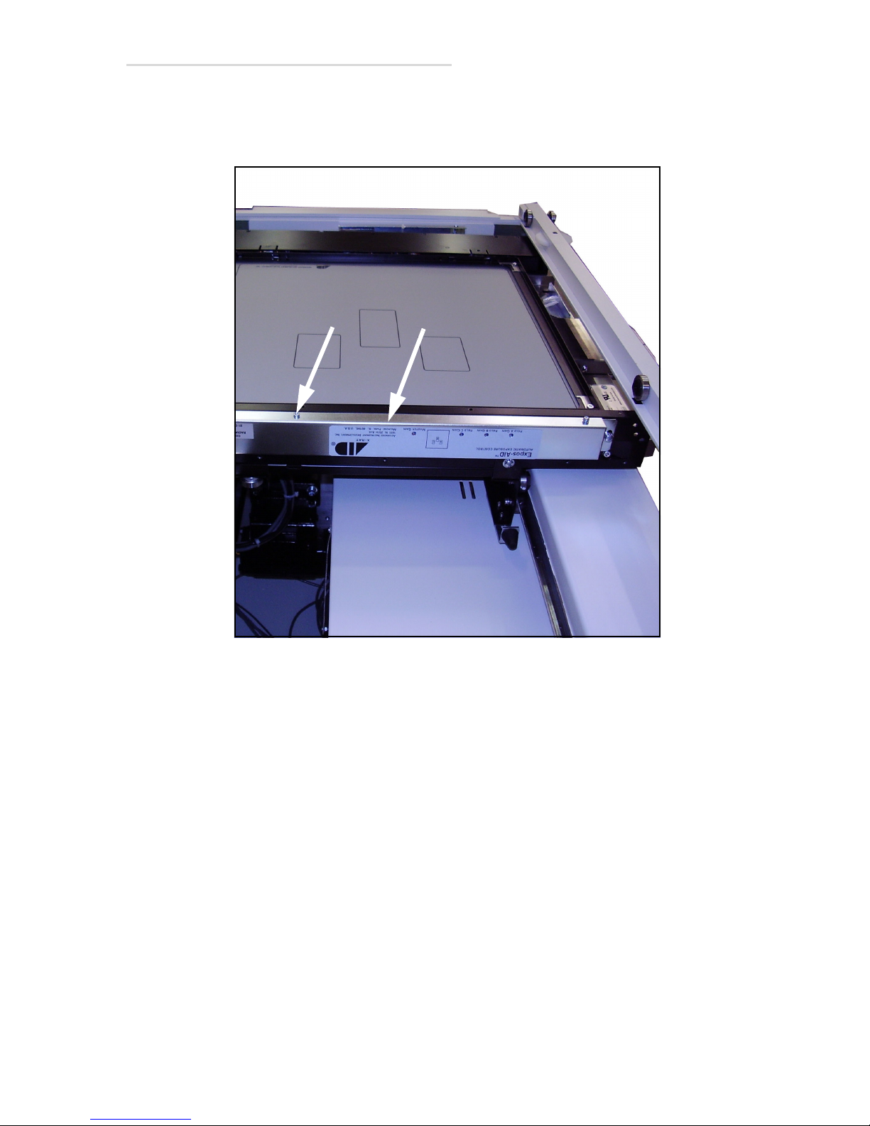
38 Reinstall the cover (1 in Figure 2-20) and secure with the four screws
(2). Make sure that the chamber mates with the grommet installed in
the previous step when reattaching the cover.
Figure 2-20. Ion Chamber Cover
2.1 Installation Instructions 2-15
Page 44
EV800 Elevating Table Installation, Operation, & Service Manual
1
2
1 (x4)
2 (x4)
Grid Installation
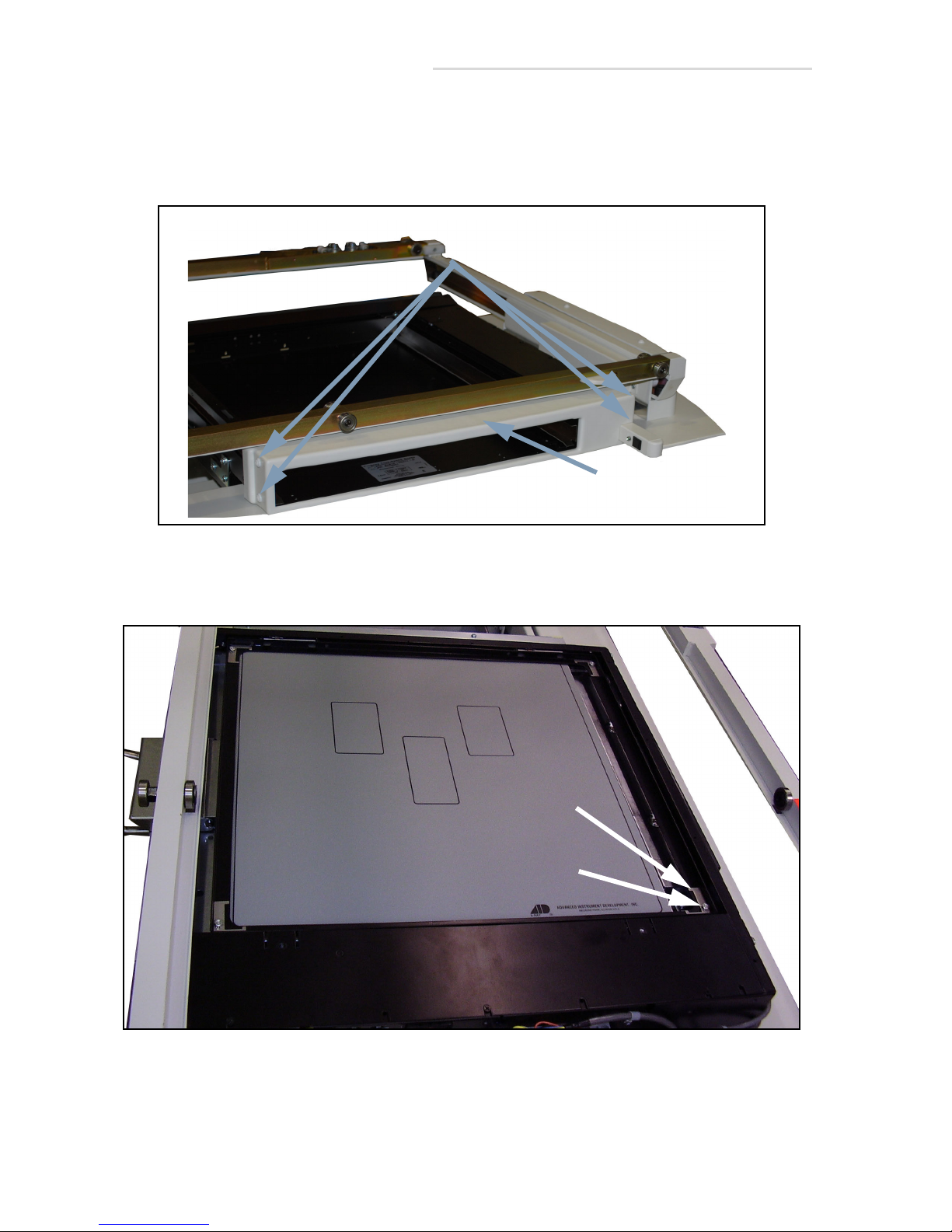
39 If not already done so, unscrew the four top cover screws (2 on each
side)(1 in Figure 2-21) then remove the top cover (2).
Figure 2-21. Bucky Top Covers
40 Unscrew the four clamp screws (1 in Figure 2-22) and remove the
clamps (2).
Figure 2-22. Grid Screws & Clamps
2-16 2.1 Installation Instructions
Page 45
EV800 Elevating Table Installation, Operation, & Service Manual
Caution
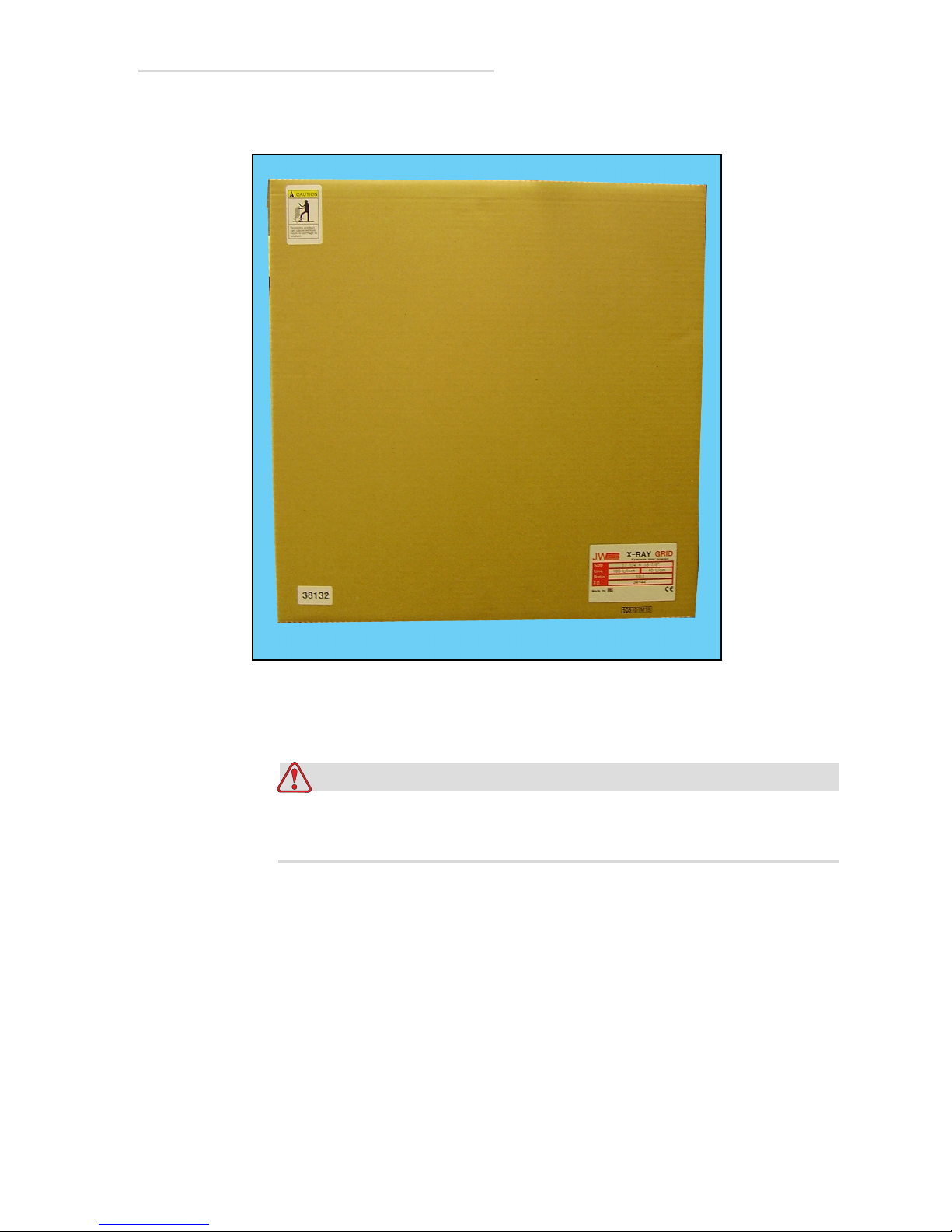
41 Unpack the grid from its box.
Figure 2-23. Grid Box (Typical)
Be careful not to over-tighten the grid clamp screws in the
following step or you may crack the grid.
2.1 Installation Instructions 2-17
Page 46
EV800 Elevating Table Installation, Operation, & Service Manual
1
2
42 Install the grid as shown below and secure in place with clamps and
screws.
Figure 2-24. Grid Installation
43 Reattach the bucky top cover (1 in Figure 2-25) and secure in place
with four screws (2).
Figure 2-25. Bucky Top Covers (Grid Not Shown)
2-18 2.1 Installation Instructions
Page 47
EV800 Elevating Table Installation, Operation, & Service Manual
Warning
1
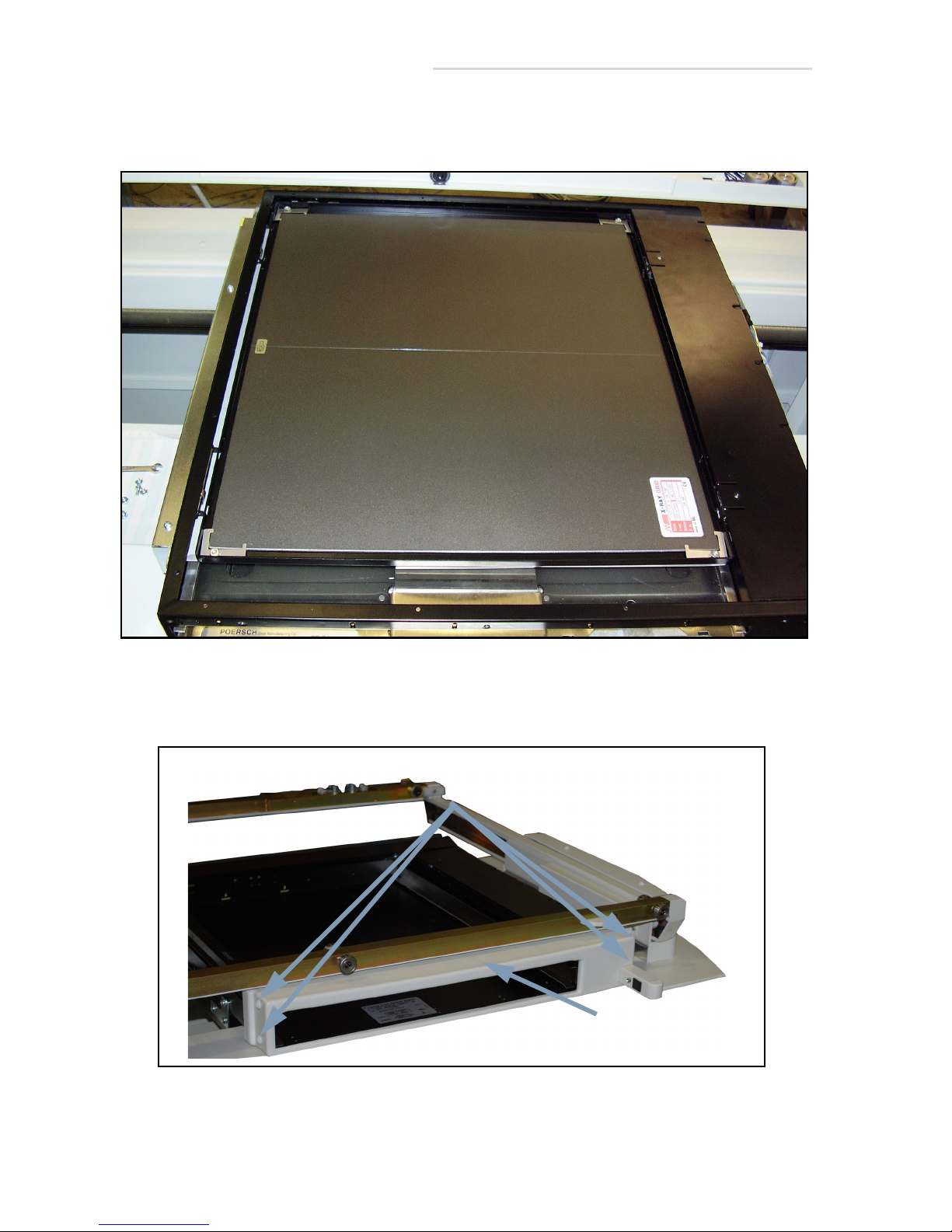
44 Feed the cables from peripheral equipment (wall bucky, collimator,
etc.) through the port (1 in Figure 2-26) in bottom of table. As an
alternative, the cables can be fed out through the opening in the lower
back of the table, shown in Figure 2-28.
Figure 2-26. Bottom Cable Port
Make sure power to the table and all peripheral equipment
(generator, tubestand, etc.) is turned off before performing the
following steps; you can be seriously injured if you do not.
45 Connect peripheral cables to base chassis according to the
interconnect schematics in Chapter 8.
2.1 Installation Instructions 2-19
Page 48
EV800 Elevating Table Installation, Operation, & Service Manual
46 Disconnect the power cord from the main chassis shown below and
remove the power cord.
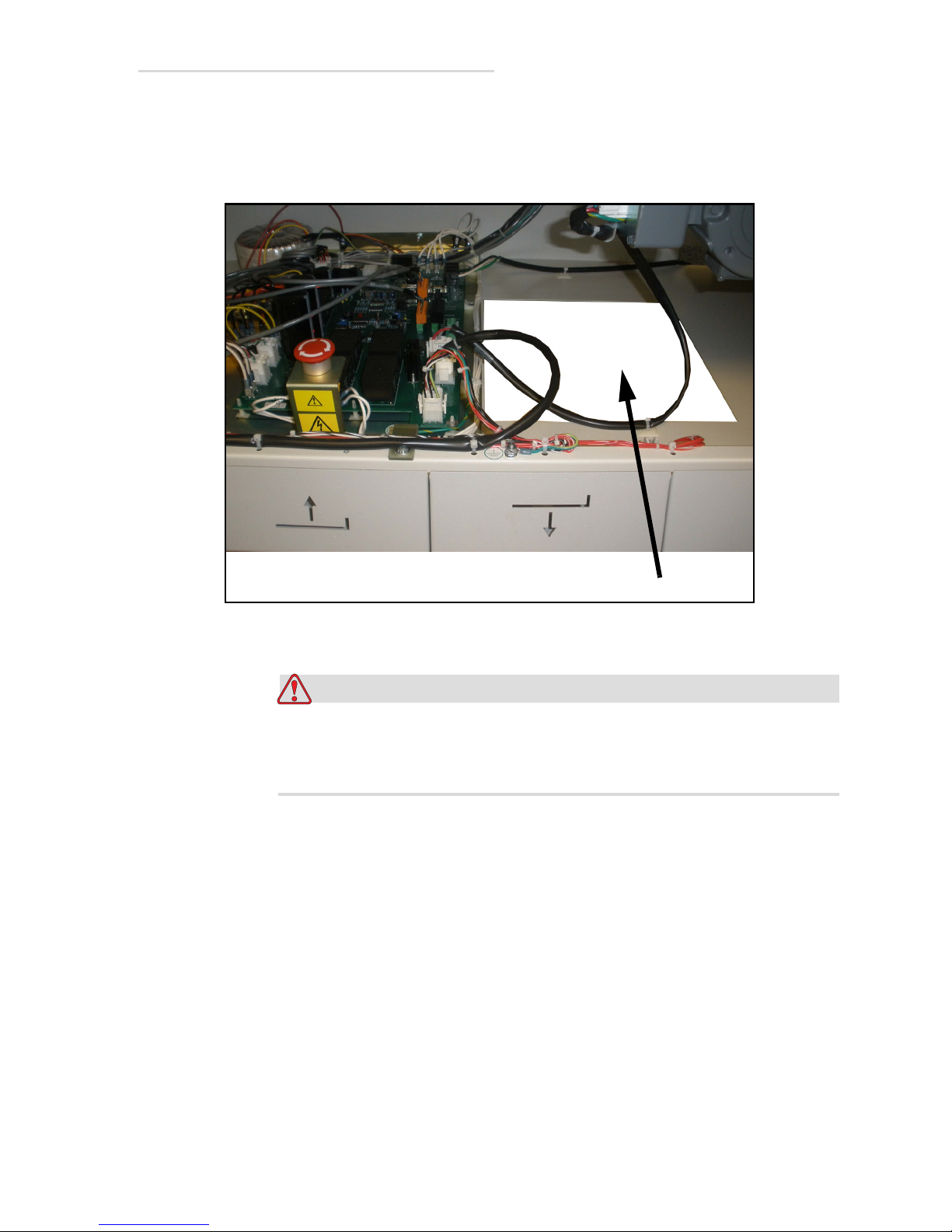
Wiring Safety Information
• X-ray apparatus shall be grounded and powered in accordance
with the National and Local Electrical Codes.
• During installation, make sure that all protective ground wire
connections are completed before the equipment is turned on.
• It is required that a separate 10-amp (min.) line disconnect and
current limiting device be provided for table power.
• The protective ground wires between system components are
connected as shown in the wiring diagram in service manual.
• Regulations of professional associations concerning safety and
accident prevention must be observed.
• When installation and maintenance is required, use only
personnel trained in the mechanical and electrical operation of
this equipment.
Caution
If you are connecting 120 nominal input voltage to this table, then
a 120 VAC needs to be connected to the line input. JP1, JP2, and
JP3 on the main board must have the jumper plugs installed
between pins 2-3.
Caution
If you are connecting 240 nominal input voltage to this table, then
a 240 VAC needs to be connected to the line input. JP1, JP2, and
JP3 on the main board must have the jumper plugs installed
between pins 1-2.
2-20 2.1 Installation Instructions
Page 49
EV800 Elevating Table Installation, Operation, & Service Manual
Warning
Power Cord
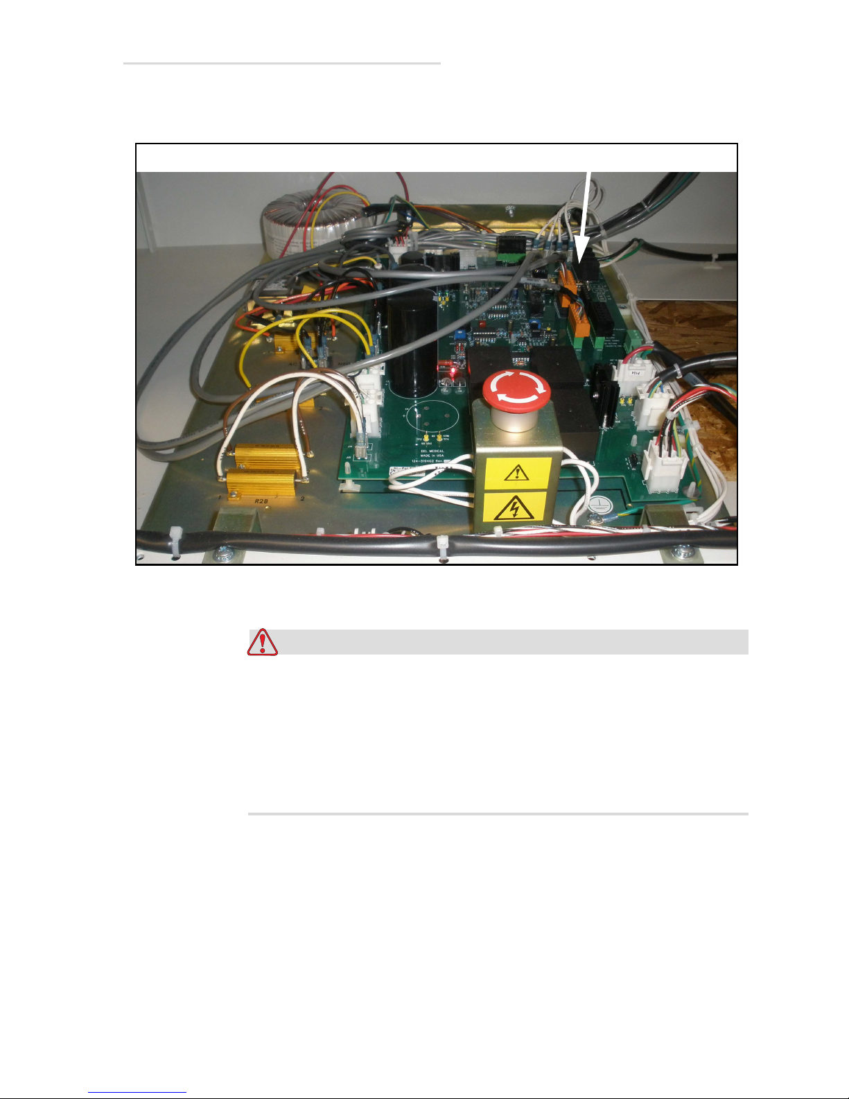
47 Connect the dedicated power line to TB102. Refer to Section 1.5
“Specifications” for information on power and wiring requirements.
Figure 2-27. Main Power Terminal
Make sure power to the table is turned off at disconnect switch
before performing the following steps.
Also, make sure power to the bucky is off by turning off the
generator before performing the following steps.
Failure to follow this warning may result in serious injury.
2.1 Installation Instructions 2-21
Page 50
EV800 Elevating Table Installation, Operation, & Service Manual
1
1
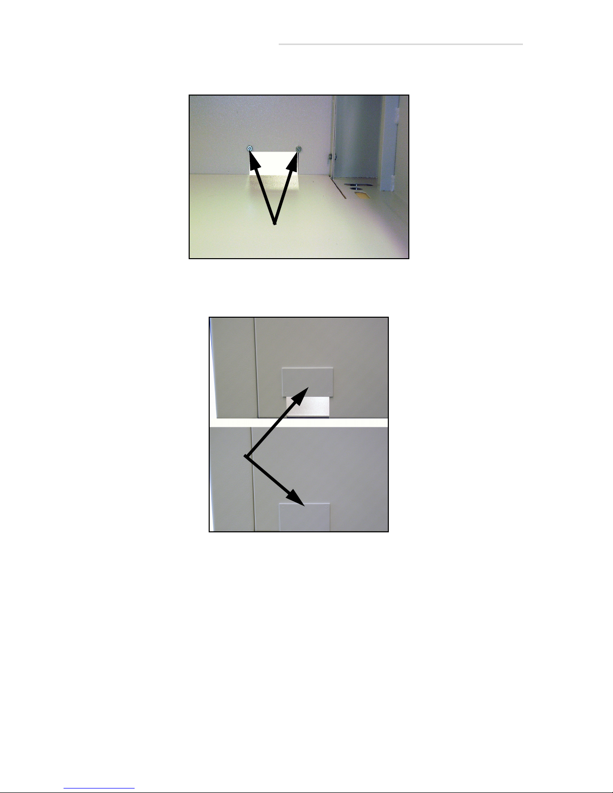
48 Unscrew the port nuts (1 in Figure 2-28).
Figure 2-28. Port Cover Nuts
49 Pull the port cover (1 in Figure 2-29) out, flip it over, and reinsert it.
Figure 2-29. Port Cover (Back View)
2-22 2.1 Installation Instructions
Page 51
EV800 Elevating Table Installation, Operation, & Service Manual
1
2
1
3
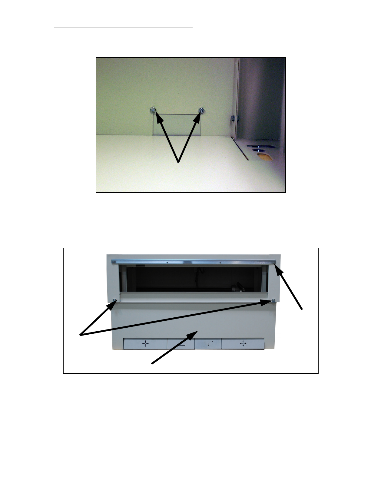
50 Secure the cover in place with nuts (1 in Figure 2-30).
Figure 2-30. Port Cover Nuts
51 Reattach the lower front cover (1 in Figure 2-31).
52 Unscrew the upper cover mounting screws (2). The screws were
screwed into the brackets for shipping.
Figure 2-31. Upper Cover Mounting Screws
2.1 Installation Instructions 2-23
Page 52
EV800 Elevating Table Installation, Operation, & Service Manual
2
1
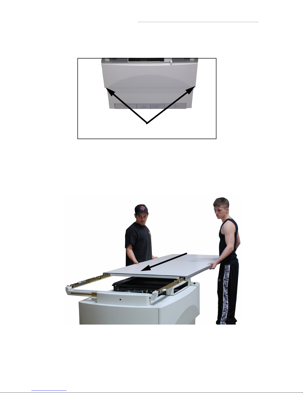
53 Hook the top cover (1 in Figure 2-32 below) onto the upper rail (3 in
Figure 2-31 above) and secure in place with the two screws (2 in
Figure 2-32 below).
Figure 2-32. Upper and Lower Panel Screws
54 Unpack the table top from its shipping box.
55 Slide table top onto base rollers as shown below. Make sure tabletop is
installed so the label is oriented towards front of the base. If you do
not have enough room to slide the table on, perform steps 58-68.
Otherwise, go to step 69.
2-24 2.1 Installation Instructions
Figure 2-33. Table Top Installation
Page 53
EV800 Elevating Table Installation, Operation, & Service Manual
2
1
1
2
2
1
2
Note: Steps 58-68 are for rooms that are too small to allow the table top to
be slid on from the end.
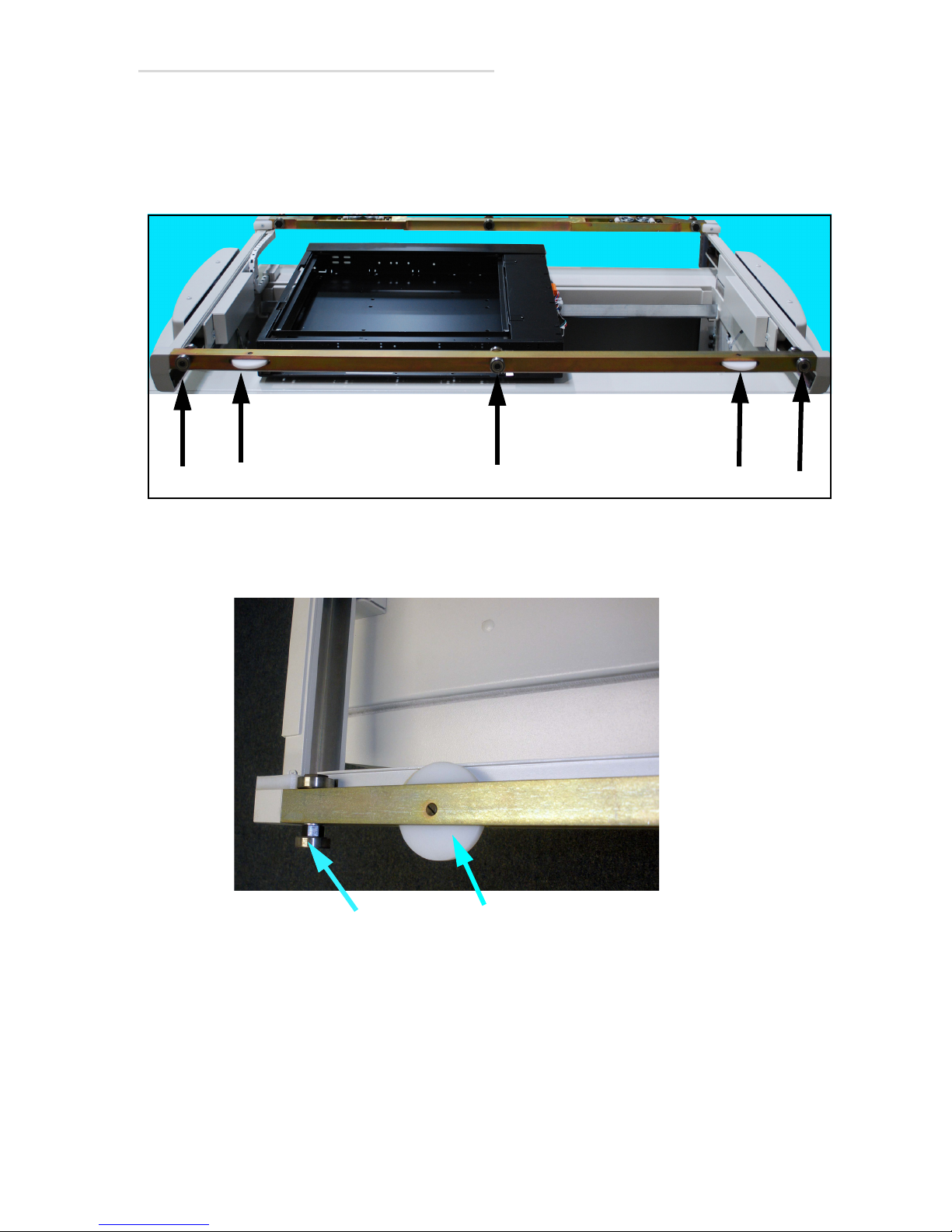
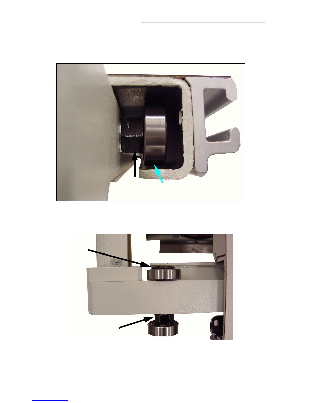
56 Remove guide rollers (1 in Figure 2-34) and bearings (2) from front of
table.
Figure 2-34. Guide Roller and Bearing Removal
57 Slide the table to the right and reinstall the left guide roller (1 in
Figure 2-35) and the left bearing assembly (2).
Figure 2-35. Left Guide Roller and Bearing
2.1 Installation Instructions 2-25
Page 54
EV800 Elevating Table Installation, Operation, & Service Manual
1
2
1
2
58 Slide the table over the left bearing assembly.
59 Adjust the eccentric nut (1 in Figure 2-36) so that a gap (2) of about 1/
32” (0.8mm) appears between the bearing and the table frame.
Figure 2-36. Eccentric Adjustment
60 While holding the eccentric nut (1 in Figure 2-37) still, tighten the
bearing nut (2).
Figure 2-37. Tightening Bearing Nut
61 Repeat steps 60-63 for right side guide roller and bearing.
2-26 2.1 Installation Instructions
Page 55
EV800 Elevating Table Installation, Operation, & Service Manual
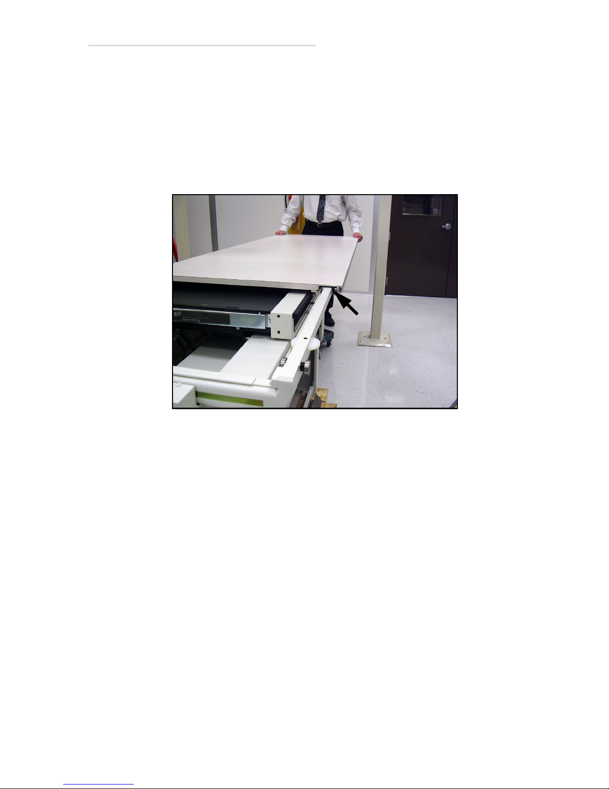
1
62 Have your partner slide the table half way off and hold it there as
shown below.
63 Install the middle bearing (1 in Figure 2-38) and adjust it as you did
for the others.
64 Slide the table top back and forth to ensure smoothness of motion.
Readjust bearing gap if required.
65 Center the table top on the table base and go to the next step.
Figure 2-38. Middle Bearing
2.1 Installation Instructions 2-27
Page 56
EV800 Elevating Table Installation, Operation, & Service Manual
Warning
1
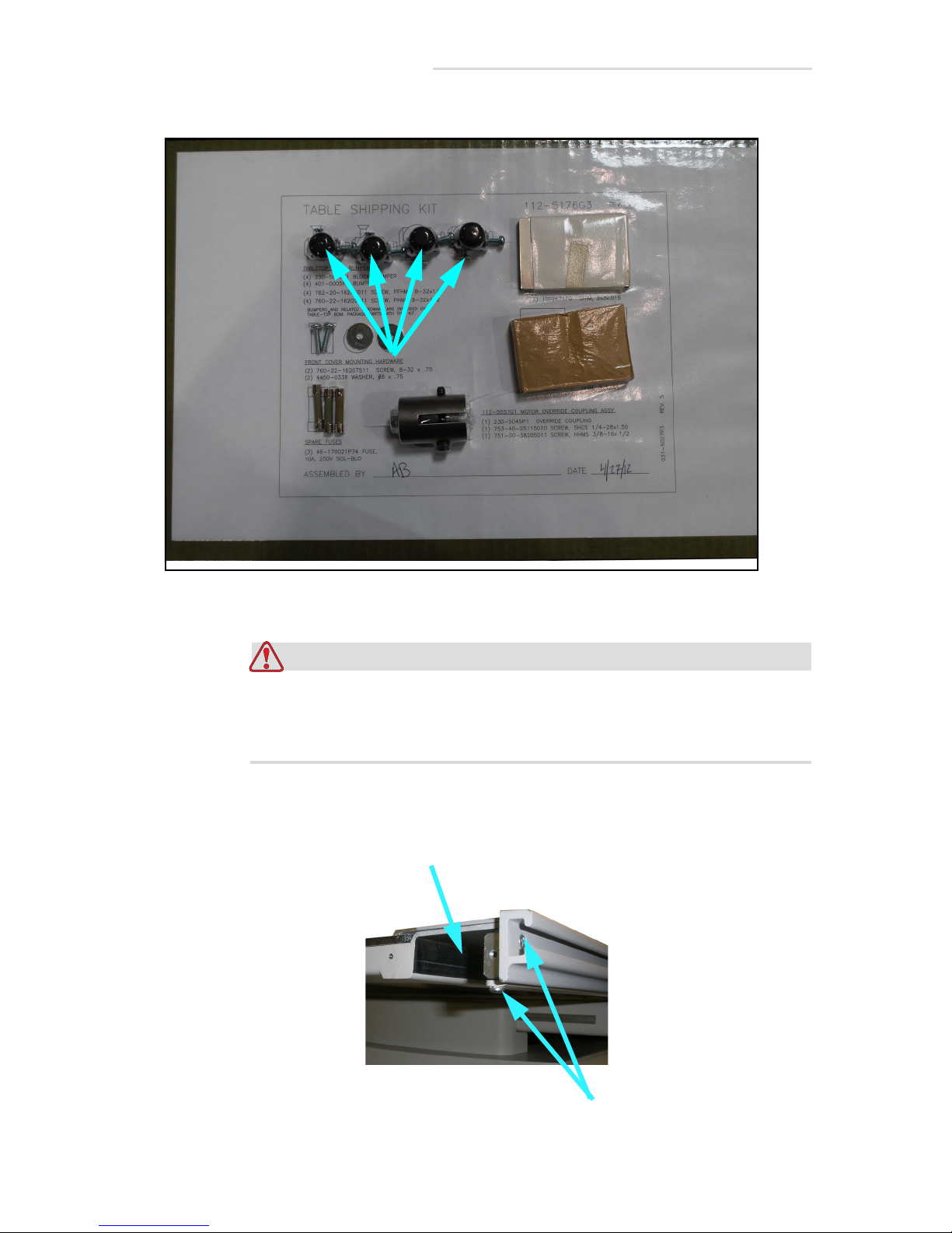
1
66 Remove four bumpers (1 in Figure 2-39) from accessory kit.
Figure 2-39. Bumpers
The bumpers must be installed. If they are not, the table top may
slide off of its base during use and severely injure the patient or
operator.
67 Mount the bumper (1 in Figure 2-40) with two screws (2) in all four
corners of table.
Figure 2-40. Bumper Mounting
2-28 2.1 Installation Instructions
Page 57

EV800 Elevating Table Installation, Operation, & Service Manual
Caution
Testing Collision Avoidance Switches
This will test if the table will stop if it collides with an object when moving
downward.
68 Move the table top to its leftmost position.
69 Turn on power to the table.
70 Run table to its highest position.
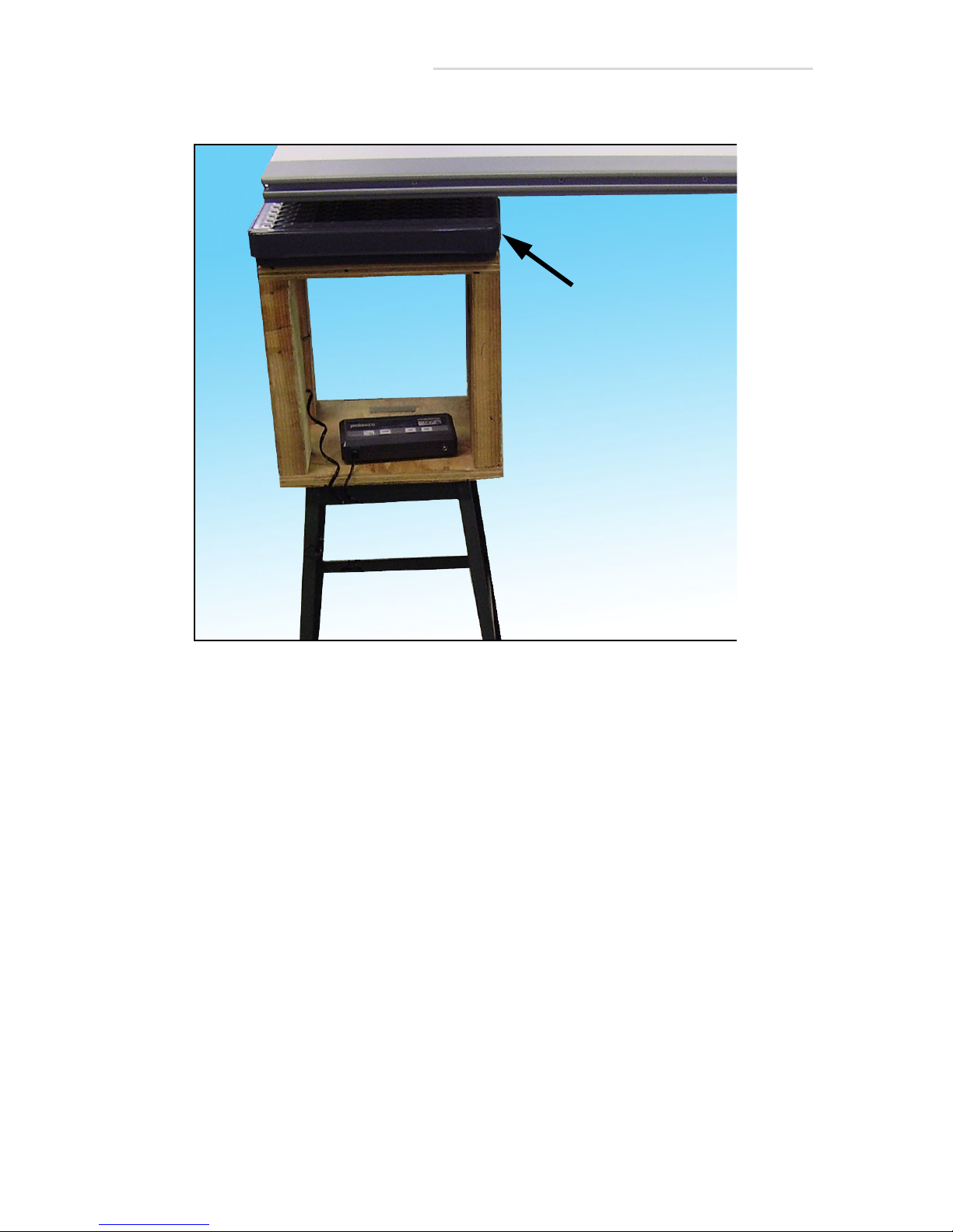
71 Place a stool or other sturdy support under the left end of the table top
as shown in Figure 2-41 below.
72 Place a weight scale on the stool.
Do not exceed 110 lbs (49 Kg) of force in the following step or the
table may get damaged. If the force appears that it will exceed 110
lbs (49 Kg), release the down pedal immediately.
73 Press the Down pedal and lower the table until the table top contacts
the scale and the table stops by itself. The force on the scale when the
table stops should be between 90 to 110 lbs (40 to 49 Kg.). If it is not or
if the force exceeds 110lbs (49 Kg), adjust the collision avoidance
switch according to Section 5.6 “Testing & Adjusting Collision
Avoidance Switches” on page 5-12. If it is, go to the next step.
74 Raise the table back up.
75 Move the table top to its rightmost position.
2.1 Installation Instructions 2-29
Page 58
EV800 Elevating Table Installation, Operation, & Service Manual
Scale
76 Repeat steps 71-76 for right end of table top.
Figure 2-41. Scale & Stool Under Table Top
2-30 2.1 Installation Instructions
Page 59

EV800 Elevating Table Installation, Operation, & Service Manual
Cassette Tray Insertion
77 Remove the cassette tray from its shipping box.
Figure 2-42. Cassette Tray Box (Typical)
2.1 Installation Instructions 2-31
Page 60
EV800 Elevating Table Installation, Operation, & Service Manual
4 (Typical)
2
1
3
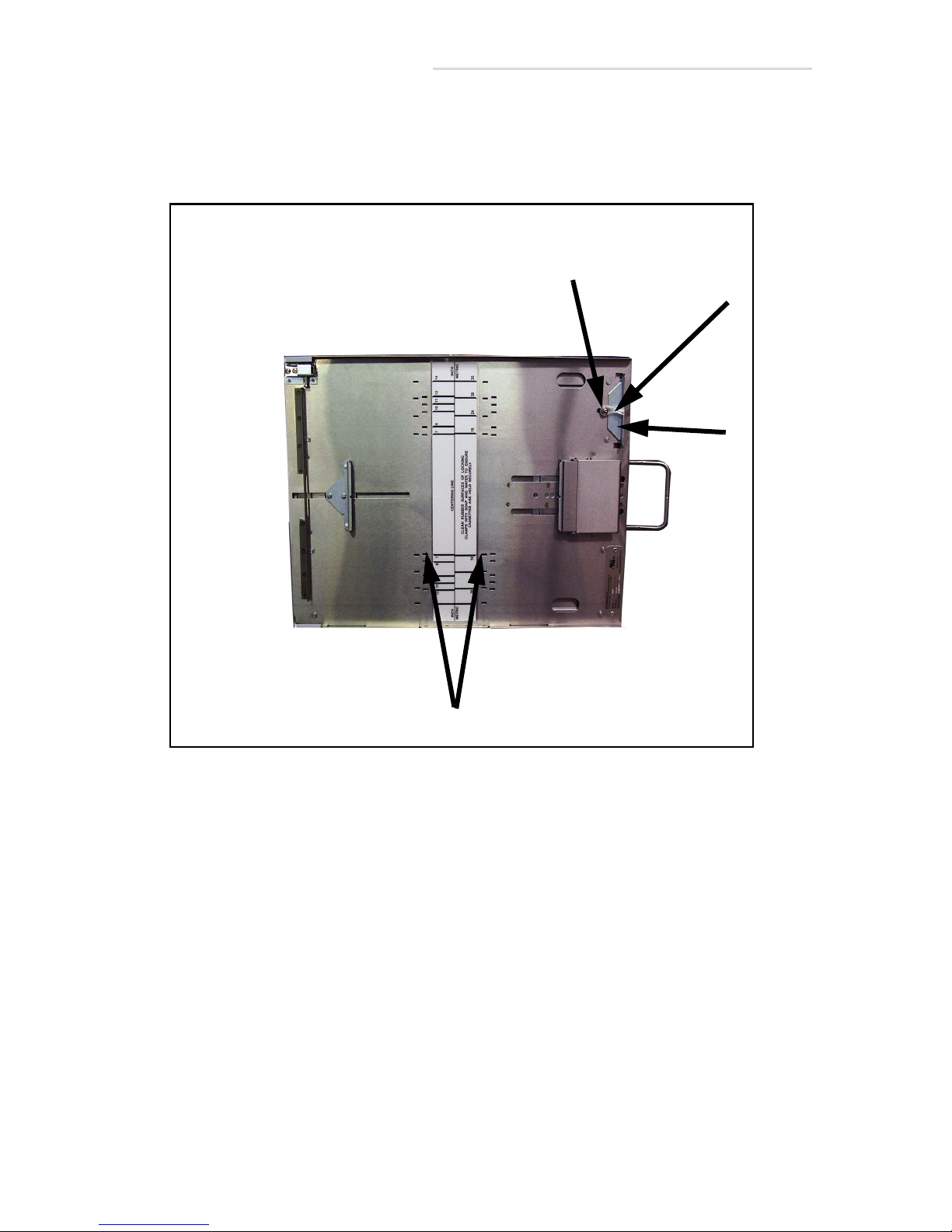
78 Remove the shipping tape (1 in Figure 2-43) from the cassette tray.
79 Pull the pin (2) back and remove the cassette blocker (3).
80 Place the guide in the desired slots (4).
Figure 2-43. Cassette Tray Preparation
2-32 2.1 Installation Instructions
Page 61
EV800 Elevating Table Installation, Operation, & Service Manual
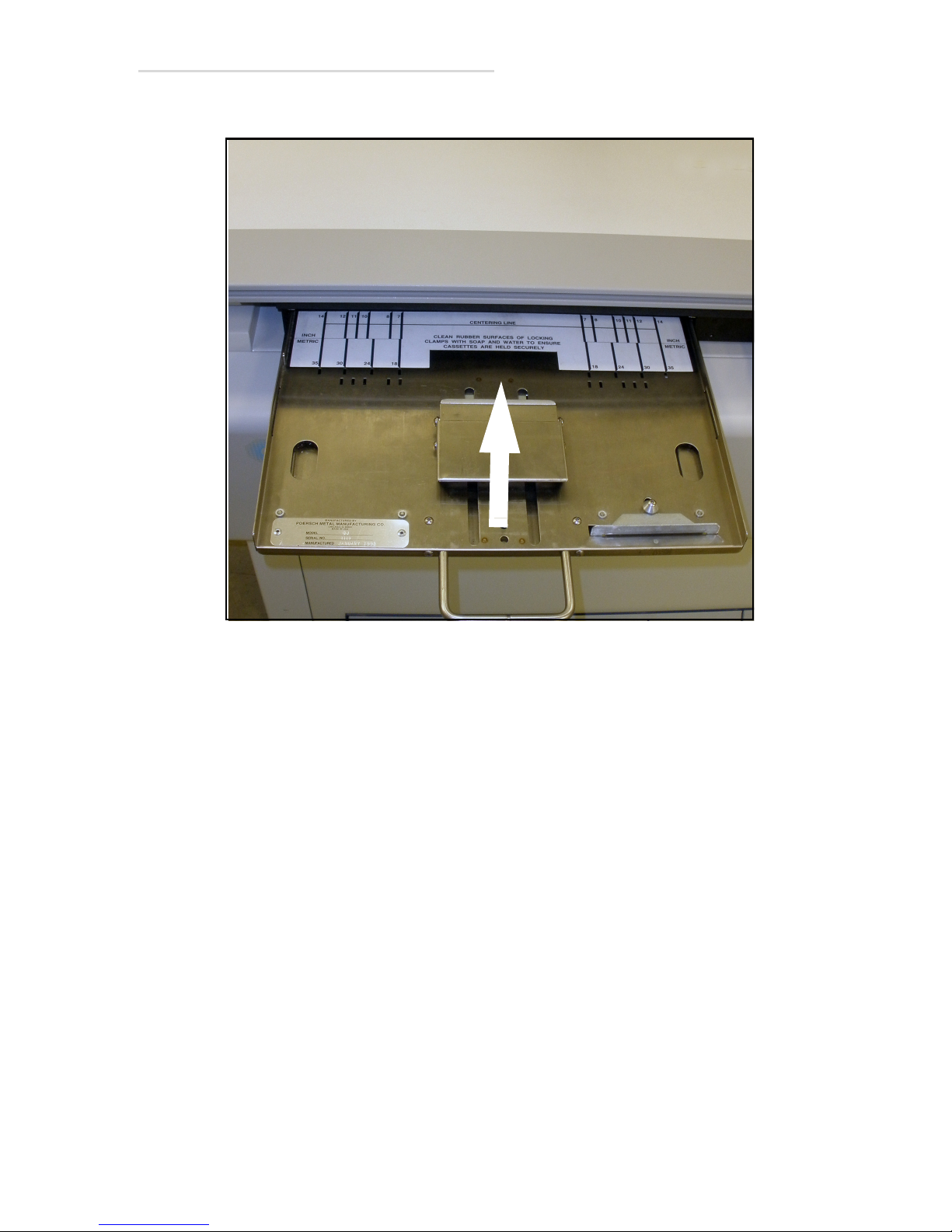
81 Insert the cassette tray into the bucky as shown in the figure below.
Figure 2-44. Cassette Tray Insertion
Installation is complete.
2.1 Installation Instructions 2-33
Page 62

EV800 Elevating Table Installation, Operation, & Service Manual
This page is intentionally left blank.
2-34 2.1 Installation Instructions
Page 63
Operation
Warning
1
3.1 Safety Precautions
Before attempting to operate the table, familiarize yourself with the safety
concerns listed in this section.
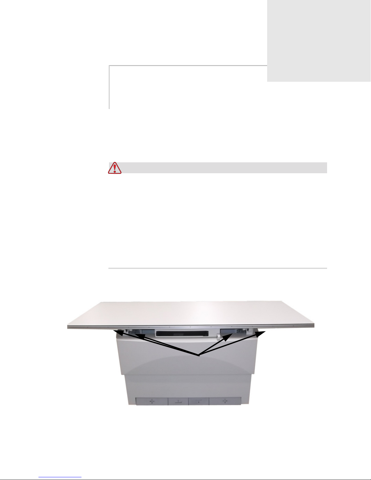
Do not place any objects within the vertical motion area above or
below table. Objects in such areas can present crush hazards (1 in
Figure 3-1) for the patient or operator, and can also damage the
table. See areas shown shaded in Figure below.
3
The table is equipped with a collision avoidance switch for
downward motion. This switch is designed to protect the table, not
the operator or patient from a collision. The downward motion of
the table will stop if the table encounters 100 lbs (44kgs) of
upward force.
Figure 3-1. Crush Hazard Areas
3.1 Safety Precautions 3-1
Page 64
EV800 Elevating Table Installation, Operation, & Service Manual
Warning
Warning
Table top lock release pedals
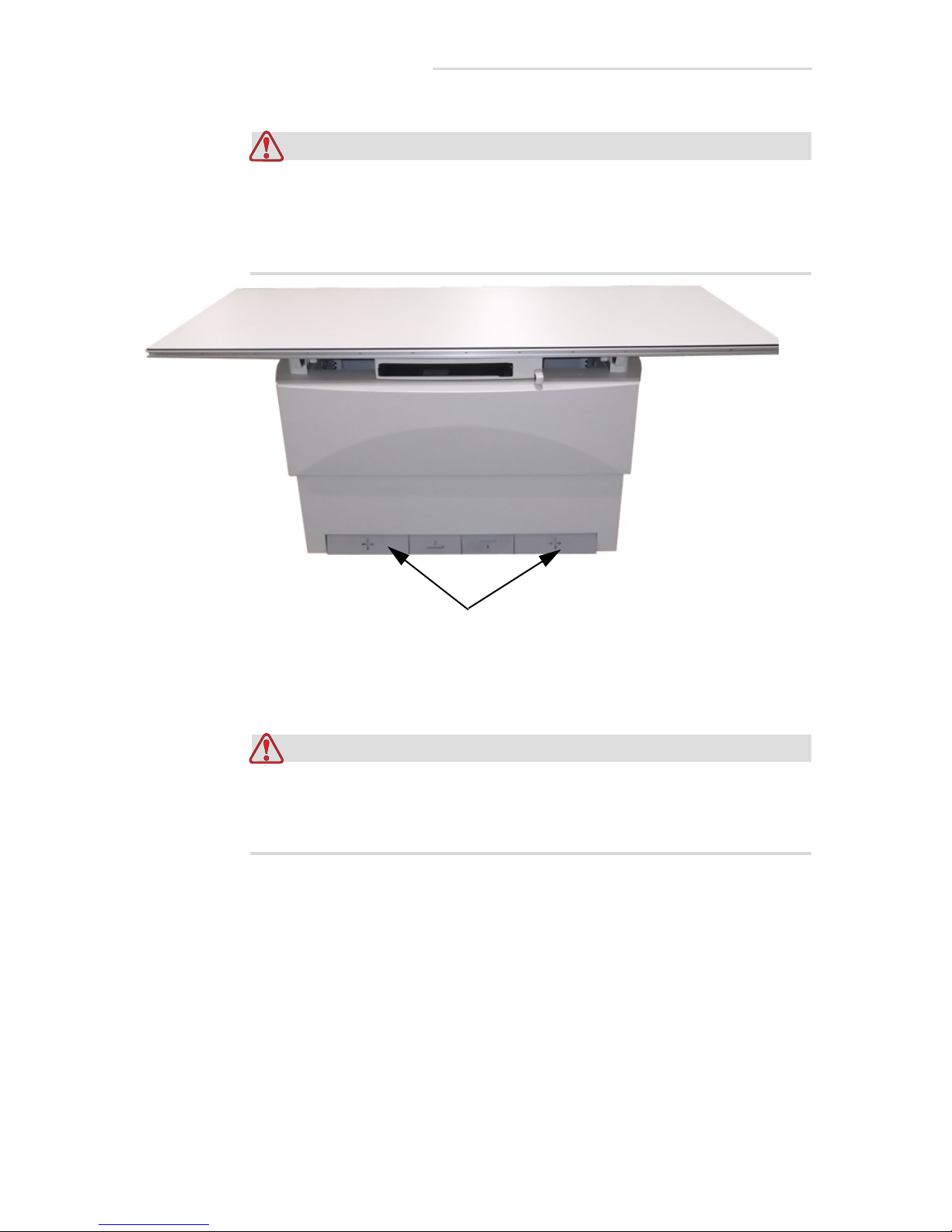
Make sure that the operator or the patient does not touch the table
top lock release pedals when the patient is getting on or off table.
This may cause the patient to fall off the table and cause serious
injury. See figure below.
Figure 3-2. Table top lock release pedal
No foreign objects which can attenuate or scatter the X-ray beam
are allowed between the X-ray tube and the table top during
exposure. Failure to follow this may result in serious injury.
3-2 3.1 Safety Precautions
Page 65

EV800 Elevating Table Installation, Operation, & Service Manual
Warning
This table is intended to be used as part of a system for the
intended generation of X-rays for medical diagnosis.
X-rays generate a potential risk for both patients and operators.
For this reason, the application of X-rays for a given medical
purpose must aim at the minimization of radiation exposure to any
persons.
Those persons responsible for the application must have the
specific knowledge according to legal requirements and
regulations and must establish safe exposure procedures for this
kind of system.
Those persons responsible for the planning and installation of this
equipment must observe the national regulations.
3.1 Safety Precautions 3-3
Page 66
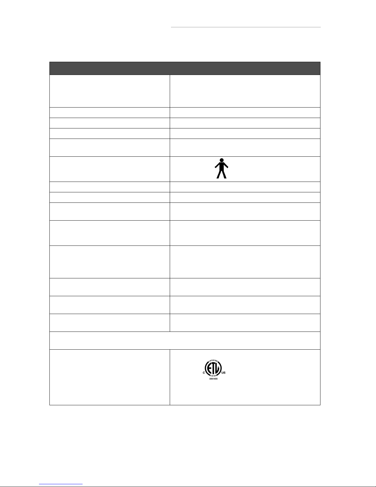
EV800 Elevating Table Installation, Operation, & Service Manual
3.2 Operation Specifications
Operation Specifications
Compatibility The EV800 Elevating Table is compatible with a wide
variety of generators, wallstands, and tubestands. It is
intended to be used in a stationary diagnostic X-ray configuration.
Voltage 120VAC or 230/240 VAC
Current 10 Amps, Momentary 15 sec ON, 85 sec OFF
Frequency 50/60 Hz Single Phase
Fuse Type Line (FL1) & (FL2) 10 Amp
Motor (F1) 8 A
Classification
Class 1 Type B
Patient Lift Limit 800 lbs (363 Kg)
Mode of Operation Momentary
Aluminum Equivalent Beam Attenuation of the Standard Table Top is 0.7 mm
Aluminum Equivalent or Less
Temperature Limits Transit/Storage Operating
– 40° F to +158° F +50° F to +95° F
– 40° C to +70° C +10° C to +35° F
Relative Humidity Limits Transit/Storage
10% to 100%
Operating
10%-80% Non-Condensing
Atmospheric Limits 14.5 inHg to 30.74 inHg
500 hPa to 1060 hPA
Degree of protection against the ingress of
water:
No user serviceable parts Classified To UL/IEC 60601-1, IEC 60601-2-32, IEC
Equipment not suitable for use in the presence of flammable anesthetic mixtures with air, oxygen or nitrous
oxide.
Certifications:
Ordinary
60601-1-3, Certified To CAN/CSA C22.2 NO. 601.1
Classified To UL 60601-1,IEC60601-1, EN60601-1, IEC
60601-2-32, EN60601-2-32, IEC60601-1-3, EN60601-1-
3. Certified To CAN/CSA C22.2 NO. 601.1.
3-4 3.2 Operation Specifications
Table 3-1: Operation Specifications
Page 67
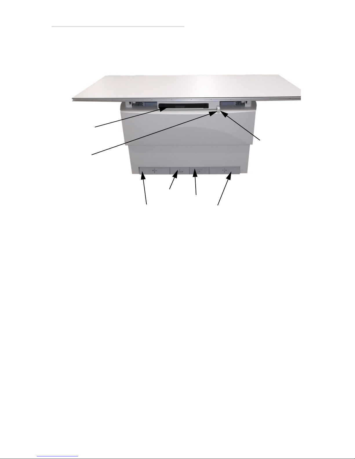
3.3 Controls
Table Top Lock Release Pedal
Up Pedal
Down Pedal
Bucky
Bucky
Carriage
Carriage
Lock Release
Table Top
Power
Indicator
This section describes the controls of the table. Figure 3-3 below shows the
controls of the table.
EV800 Elevating Table Installation, Operation, & Service Manual
Down Pedal
Press the Down pedal to lower the table. The table can be lowered to
within 22” (56cm) of the floor.
The table moves downward at a constant speed when you press and hold
the Down pedal. When the table reaches its mid-point level, it will
automatically stop. Restarting the downward motion of the table depends
on how your table was set up.
The default setup is automatic restart. In this mode, if you do not release
the pedal after the table stops, it will automatically restart after a few
seconds. The table will then continue downward until it reaches its lowest
position and automatically stops.
The optional setup is manual restart. In this mode, you release the pedal
and then press and hold the pedal again to restart motion. The table will
then continue downward until it reaches its lowest position and
automatically stops.
The procedure for changing from one mode to another is covered in
Section 5.7 and should only be performed by a service technician.
Figure 3-3. Control Pedals
3.3 Controls 3-5
Page 68

EV800 Elevating Table Installation, Operation, & Service Manual
Up Pedal
Press the Up pedal to raise the table. The table can be raised to 34” (86 cm)
above the floor.
The table moves up at a constant speed when you press and hold the Up
pedal. When the table reaches its mid-point level, it will automatically
stop. Restarting the upward motion of the table depends on how your
table was set up.
The default setup is automatic restart. In this mode, if you do not release
the pedal after the table stops, it will automatically restart after a few
seconds. The table will then continue upward until it reaches its highest
position and automatically stops.
The optional setup is manual restart. In this mode, you release the pedal
and then press and hold the pedal again to restart motion. The table will
then continue upward until it reaches its highest position and
automatically stops.
The procedure for changing from one mode to another is covered in
Section 5.7 and should only be performed by a service technician.
Table Top Lock Release Pedals
Pressing and holding the Table Top Lock Release pedals releases the
mechanical locks and allows the table top to be manually moved
transversely or longitudinally. The transverse range is 9.5” (24cm), and the
longitudinal range is 43.5”(110cm)
Releasing the Table Top Lock Release pedal locks the table to the new
selected position.
Bucky Carriage Lock Release
Pressing and holding the Bucky Carriage Lock Release on the front of
the bucky carriage releases the magnetic locks and allows the bucky to be
moved longitudinal to the required position under the patient. The total
travel range for the bucky is 22” (56 cm)
Releasing the switch secures the bucky in place.
Refer to the bucky’s manual for proper operation of the bucky.
Power Indicator
Indicates that power to the table is turned on and that the table is ready to
operate.
3-6 3.3 Controls
Page 69
EV800 Elevating Table Installation, Operation, & Service Manual
1
3.4 Cassette Tray Removal
To completely remove the cassette tray, do the following:
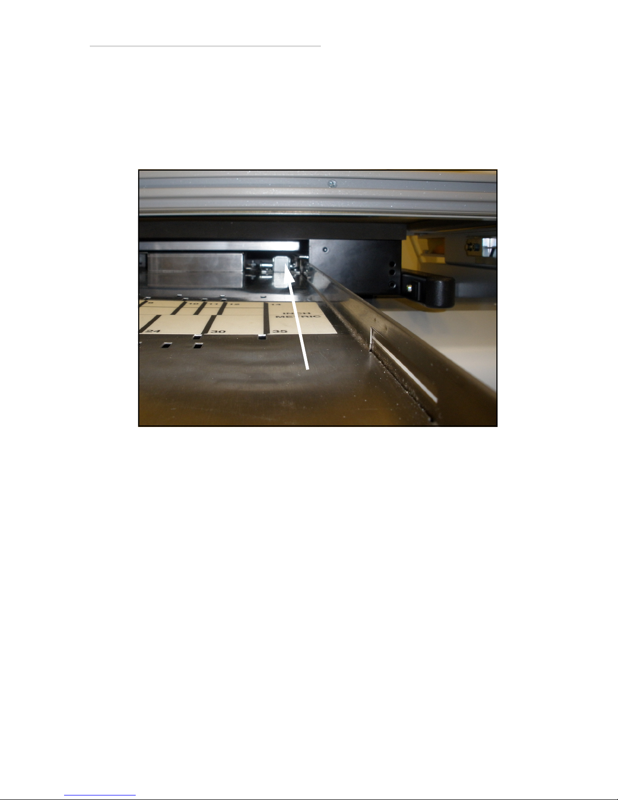
1 Manually pull the cassette tray out as far as it will go.
2 While pressing on the limit button (1 in Figure 3-4) pull the cassette
tray completely out of the bucky.
Figure 3-4. Cassette Tray Removal
3.4 Cassette Tray Removal 3-7
Page 70
EV800 Elevating Table Installation, Operation, & Service Manual
Warning
Emergency Stop Button
3.5 Emergency Stop Button (For Service Technicians
Only)
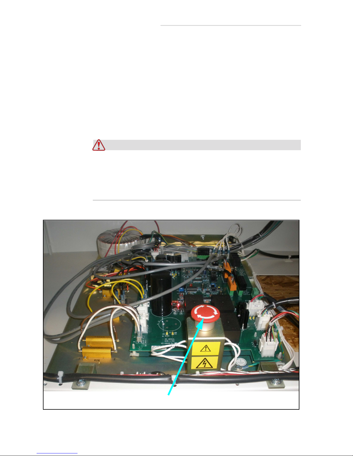
There is an Emergency Stop button located inside the table’s base that can
be pressed to stop the motion of the table in an emergency. It is meant only
to be used by technicians who are troubleshooting the table.
If the button is pressed, it must be turned in the direction of the arrows on
the button until the button pops back up in order to reset the button.
Otherwise, the table cannot be restarted. See Figure 3-5 below for location
of button.
The Emergency Stop button DOES NOT turn off all power to the
table. There may still be lethal voltages present on the main
chassis and throughout the table when this button is turned off.
These voltages come from sources outside the table (i.e. generator,
wallstand, etc.) that are connected to the table.
Figure 3-5. Emergency Stop Button
3-8 3.5 Emergency Stop Button (For Service Technicians Only)
Page 71
Periodic Maintenance
4.1 Periodic Maintenance Schedule
Refer to the schedule below for information on when to perform periodic
maintenance on the table.
Note: Due to varying operating conditions, the procedures listed below
may have to be performed at greater or lesser intervals. You may have to
adjust intervals according to your table’s performance.
What to Do When to Do It Refer to Section
Clean External Surfaces Every Week or as Required “4.2 Cleaning External Sur-
4
faces” on page 4-2
Grease Lift Racks Every 6 Months “4.3 Greasing Lift Racks” on
page 4-4
Check Chain Tension Every 6 Months “4.4 Checking & Adjusting
Chain Tension” on page 4-7
Table 4-1: Periodic Maintenance Schedule
4.1 Periodic Maintenance Schedule 4-1
Page 72
EV800 Elevating Table Installation, Operation, & Service Manual
Warning
Warning
4.2 Cleaning External Surfaces
Tools Required:
• Cleaning wipes
•Non-abrasive, hospital-grade cleaner
Use cleaning wipes and non-abrasive, hospital-grade cleaner to clean
external surfaces of table and base.
Turn off all electrical power to the table and all its peripheral
equipment (generator, tubestand, etc.) at the power sources before
servicing the table. Also, make sure that the power sources are
locked out and tagged “Equipment Being Serviced” before
servicing the table. Some components inside the table have power
sources other than that of the table, which is why all peripheral
equipment must be turned off; you could get seriously injured if
you not.
This equipment is NOT classified as anaesthetic-proof and may
ignite inflammable anesthetics. Flammable agents used for skin
cleaning or disinfecting may also produce an explosion hazard.
• Ensure the power has been disconnected and that the emergency
switches have been activated before starting any cleaning operation.
• Ensure no liquid gets into the unit.
• Do not immerse the equipment, including any components or
accessories, in liquid.
• Do not autoclave the equipment, including any component or
accessories.
• Do not use water. Water can short-circuit the electrical installation and
cause corrosion to mechanical parts.
• Do not use acid or abrasive products.
• Use only a dry cloth to clean chrome-plated parts.
4-2 4.2 Cleaning External Surfaces
Page 73

EV800 Elevating Table Installation, Operation, & Service Manual
• Only the surface areas of unit parts, including accessories and
connection cables, should be disinfected using a gaseous disinfectant.
For safety reasons, do not spray disinfectants.
• Clean painted parts with a cloth and use products appropriate for
cleaning plastic materials. After cleaning, wipe the surfaces with a
clean, dry cloth.
• Do not spray cleaning or disinfection solution directly on the
equipment. To disinfect, moisten a cloth with a 70% Isopropyl alcohol
solution or equivalent and wipe the surface of the equipment.
• When disinfecting the examination room ensure the unit is covered
with plastic sheets.
4.2 Cleaning External Surfaces 4-3
Page 74
EV800 Elevating Table Installation, Operation, & Service Manual
Warning
1
2
4.3 Greasing Lift Racks
Tools Required:
• 5/16” nut driver
• Cleaning wipes
• Medium phillips screwdriver
• Mobilith AW2 grease or No. 2 lithium equivalent
• Small, stiff brush to apply grease
1 Run table to its uppermost position.
Turn off all electrical power to the table and all its peripheral
equipment (generator, tubestand, etc.) at the power sources before
servicing the table. Also, make sure that the power sources are
locked out and tagged “Equipment Being Serviced” before
servicing the table. Some components inside the table have power
sources other than that of the table, which is why all peripheral
equipment must be turned off; you could get seriously injured if
you not.
2 Turn off all power to the table.
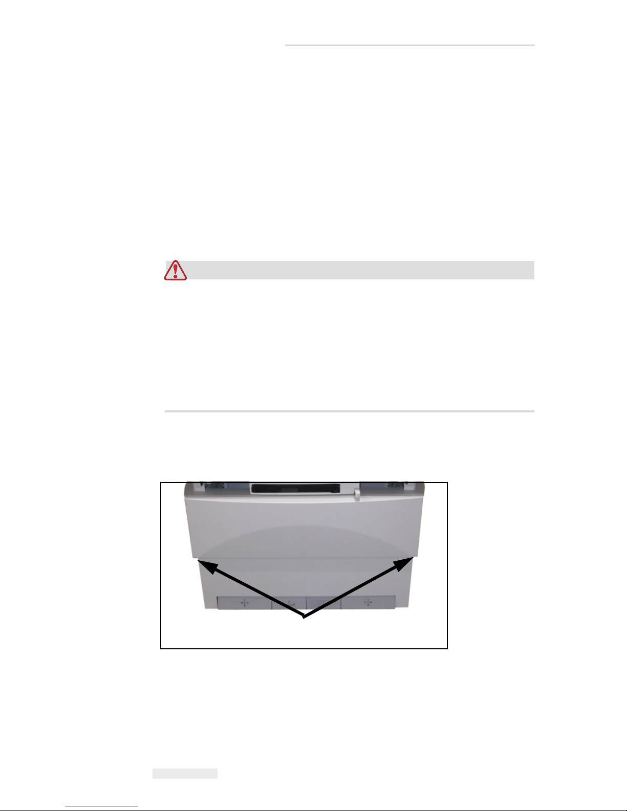
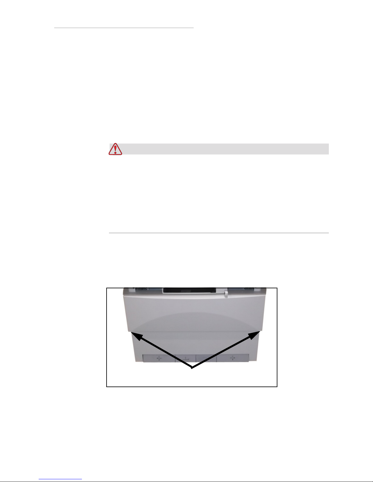
3 Unscrew the upper panel screws (1 in Figure 4-1), tilt panel (2) out,
and lift off from the table.
Figure 4-1. Upper Panel Screws
4-4 4.3 Greasing Lift Racks
Page 75
1
3
4
2
EV800 Elevating Table Installation, Operation, & Service Manual
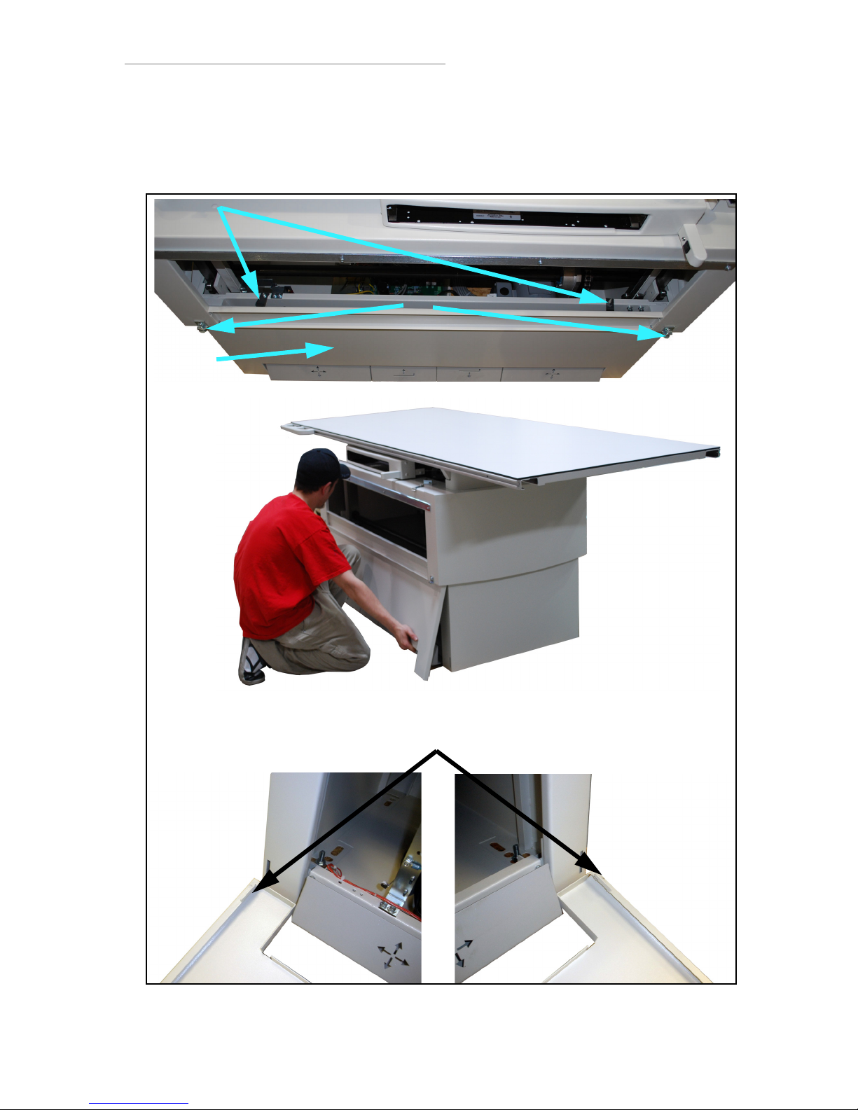
4 Unscrew the two lower panel clamps screws (1 in Figure 4-2), then
remove the upward panhead screws (2) .
5 Lift the lower panel (3) up slightly and then pull it out. The bottom of
the lower panel is connected to the table by slots (4) shown below.
Figure 4-2. Lower Panel Clamps
4.3 Greasing Lift Racks 4-5
Page 76
EV800 Elevating Table Installation, Operation, & Service Manual
1
1
Left Side
Right Side
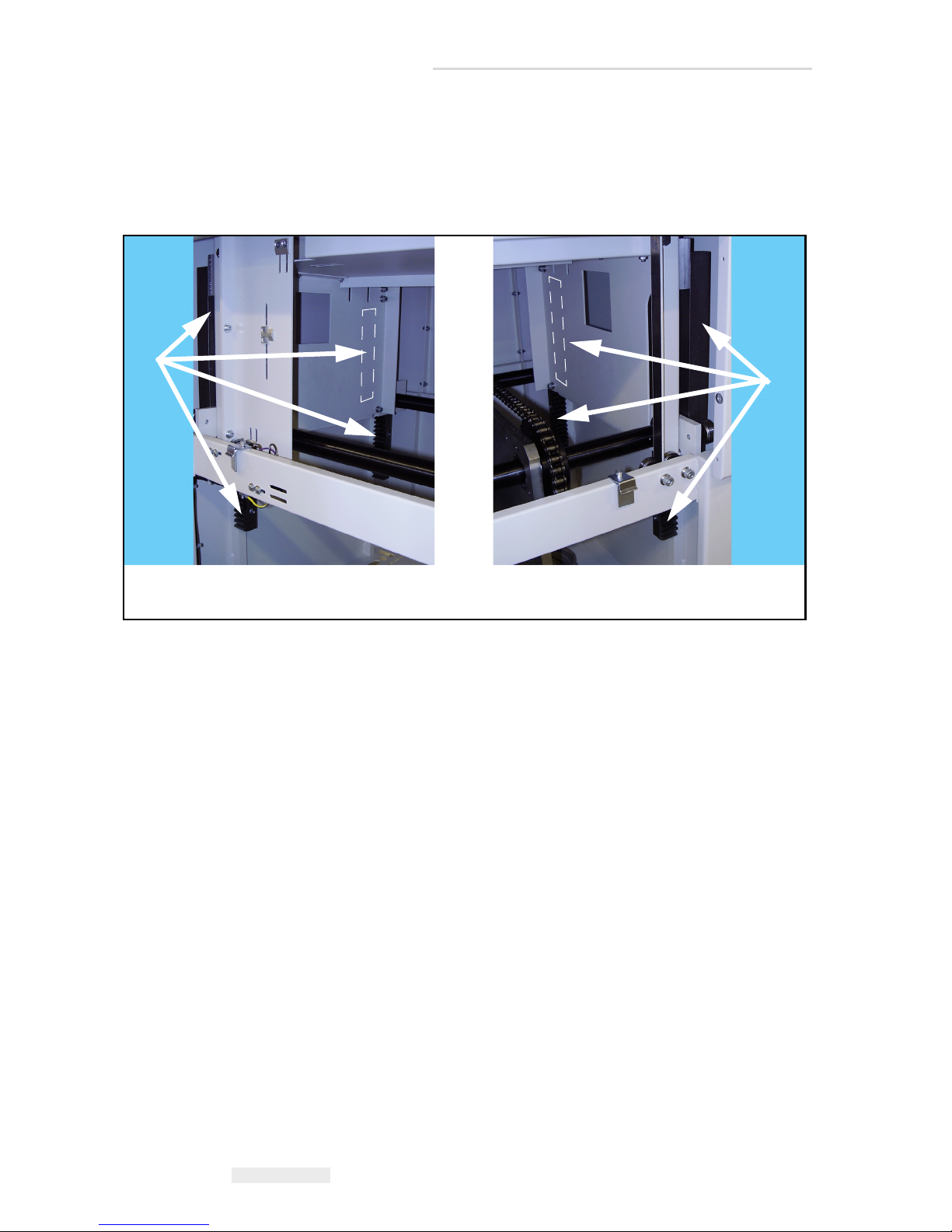
6 Using a brush, apply a medium film of Mobilith AW2 grease to the
gear faces of each of the eight racks (1 in Figure 4-3).
7 Wipe up any spilled grease.
8 Reverse steps to reassemble.
Figure 4-3. Rack Location
4-6 4.3 Greasing Lift Racks
Page 77
EV800 Elevating Table Installation, Operation, & Service Manual
Warning
1
2
4.4 Checking & Adjusting Chain Tension
Tools Required:
• Set of hex wrenches
• Scale (ruler) at least 6” (150mm) long
• Two open-end 9/16” wrenches
1 Run table to its uppermost position
Turn off all electrical power to the table and all its peripheral
equipment (generator, tubestand, etc.) at the power sources before
servicing the table. Also, make sure that the power sources are
locked out and tagged “Equipment Being Serviced” before
servicing the table. Some components inside the table have power
sources other than that of the table, which is why all peripheral
equipment must be turned off; you could get seriously injured if
you not.
2 Turn off all power to the table.
3 Unscrew the two upper panel screws (1 in Figure 4-4).
4 Unscrew the upper panel screws (1 in Figure 4-4), tilt panel (2) out,
and lift off from the table.
Figure 4-4. Upper Panel Screws
4.4 Checking & Adjusting Chain Tension 4-7
Page 78
1
3
4
2
EV800 Elevating Table Installation, Operation, & Service Manual
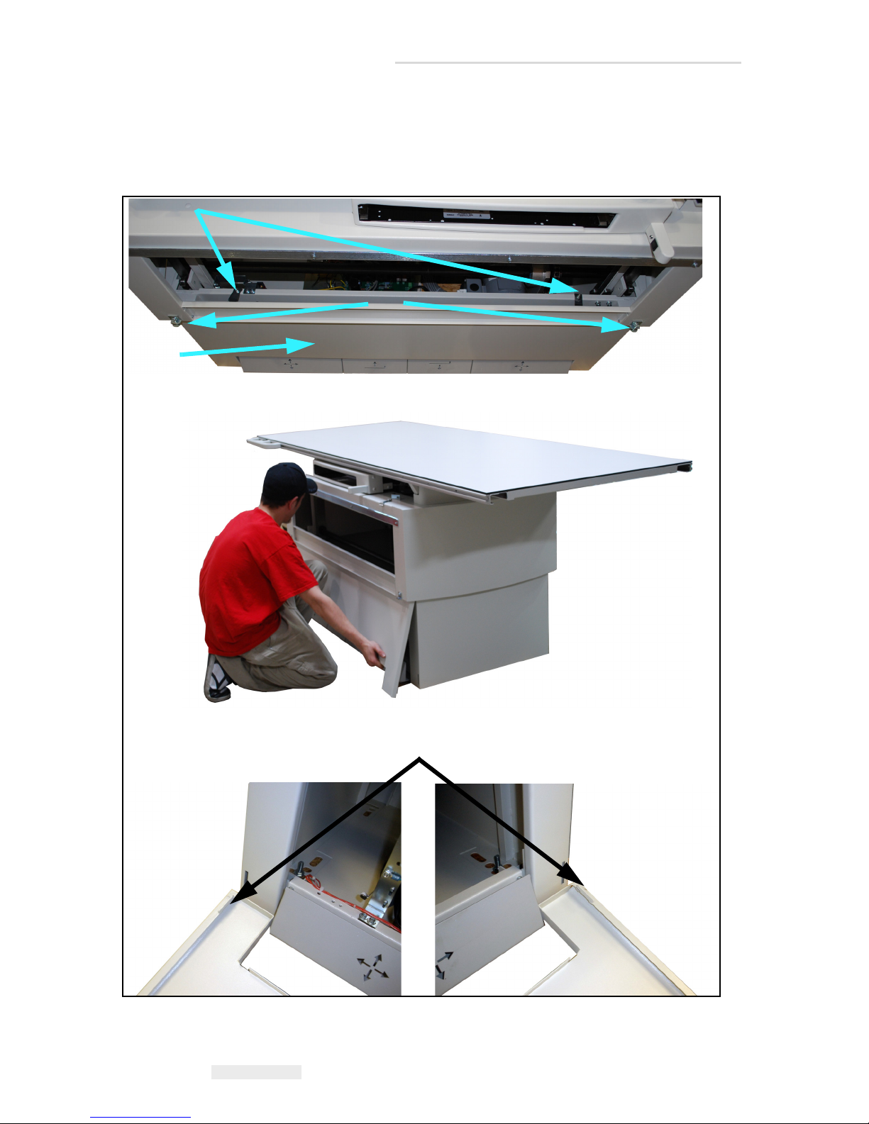
5 Unscrew the two lower panel clamps screws (1 in Figure 4-2), then
remove the lower panhead screws (2).
6 Lift the lower panel (3) up slightly and then pull it out. The bottom of
the lower panel is connected to the table by slots (4) shown below.
Figure 4-5. Lower Panel Clamps
4-8 4.4 Checking & Adjusting Chain Tension
Page 79
EV800 Elevating Table Installation, Operation, & Service Manual
1
1
Step 12 - tension added here
Step 13 - tension added here
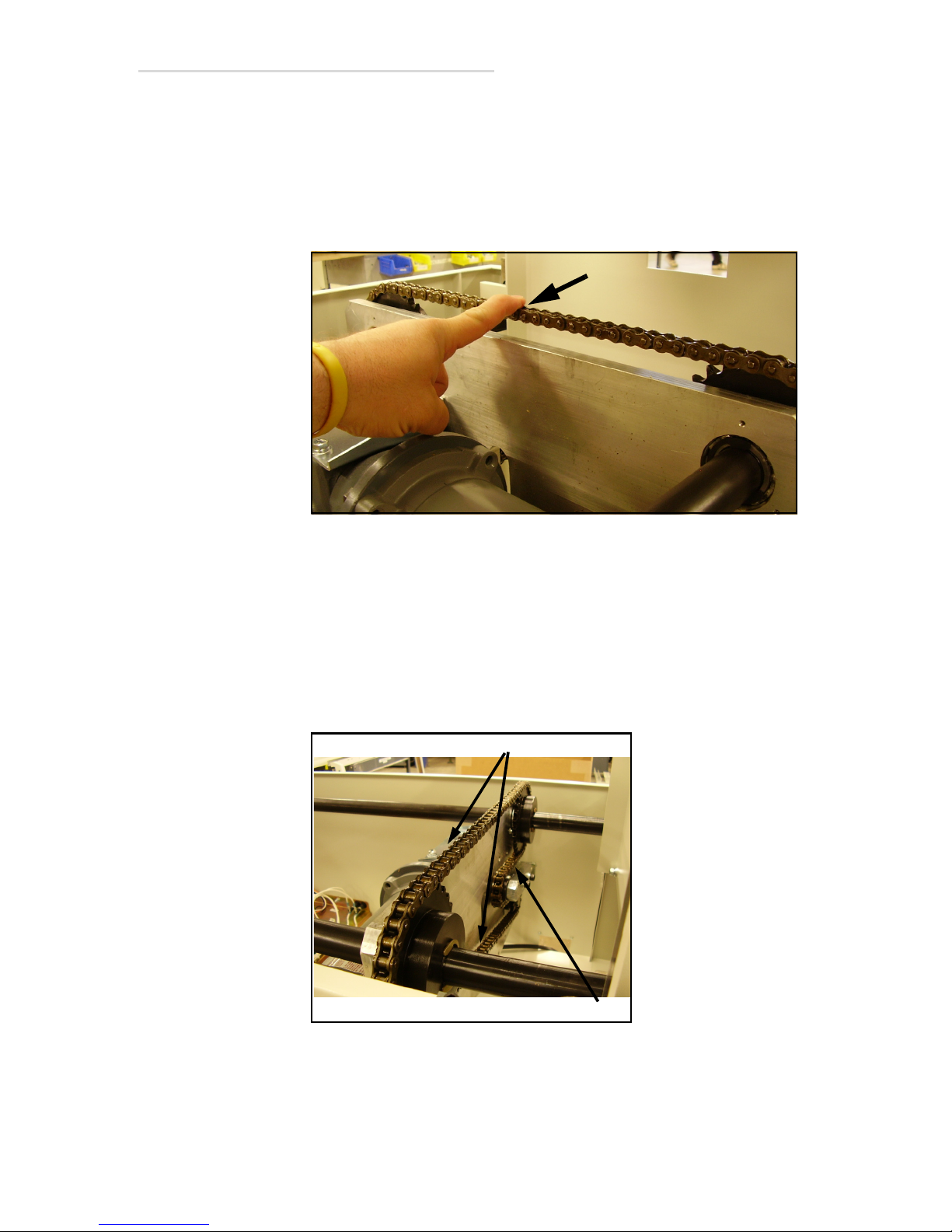
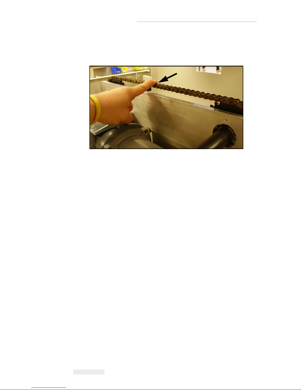
7 With the chain now tight between the three sprockets, remove the
remaining slack by tightening the chain tension bolt. When properly
tensioned, the chain should deflect approximately 3/16” at point
shown with moderate finger pressure. If tension is OK, reassemble
table. If tension is more than 3/16”, tighten chain according to the
steps that follow.
Figure 4-6. Check Chain Tension
8 Verify that the chain is completely engaged on the drive sprocket,
tensioner, and the two drive shaft sprockets. Using hand force only,
turn the input shaft of the gearbox clockwise to tighten the chain on
the small drive sprocket and the two drive shaft sprockets. The small
drive sprocket should turn in a counter-clockwise direction when
observed from the chain side of the aluminum motor/gearbox
mounting plate.
Figure 4-7. Adjusting Chain Tension
4.4 Checking & Adjusting Chain Tension 4-9
Page 80
EV800 Elevating Table Installation, Operation, & Service Manual
1
9 With the chain now tight between the three sprockets, remove the
remaining slack by tightening the chain tension bolt. When properly
tensioned, the chain should deflect approximately 3/16” at the point
shown with moderate finger pressure.
Figure 4-8. Braces in place under the upper frame gear racks
10 Reassemble table.
4-10 4.4 Checking & Adjusting Chain Tension
Page 81

Maintenance
5.1 Introduction
This chapter provides the maintenance and adjustment procedures for the
elevating table.
5
5.1 Introduction 5-1
Page 82
EV800 Elevating Table Installation, Operation, & Service Manual
Warning
1
2
5.2 Removing Front Panels
This is a common procedure that is referenced to in many of the
replacement procedures that follow in this chapter.
Tools Required:
• 5/16” nut driver
• Medium Phillips screwdriver
1 Run table to its uppermost position.
Turn off all electrical power to the table and all its peripheral
equipment (generator, tubestand, etc.) at the power sources before
servicing the table. Also, make sure that the power sources are
locked out and tagged “Equipment Being Serviced” before
servicing the table. Some components inside the table have power
sources other than that of the table, which is why all peripheral
equipment must be turned off; you could get seriously injured if
you not.
2 Turn off all power to the table.
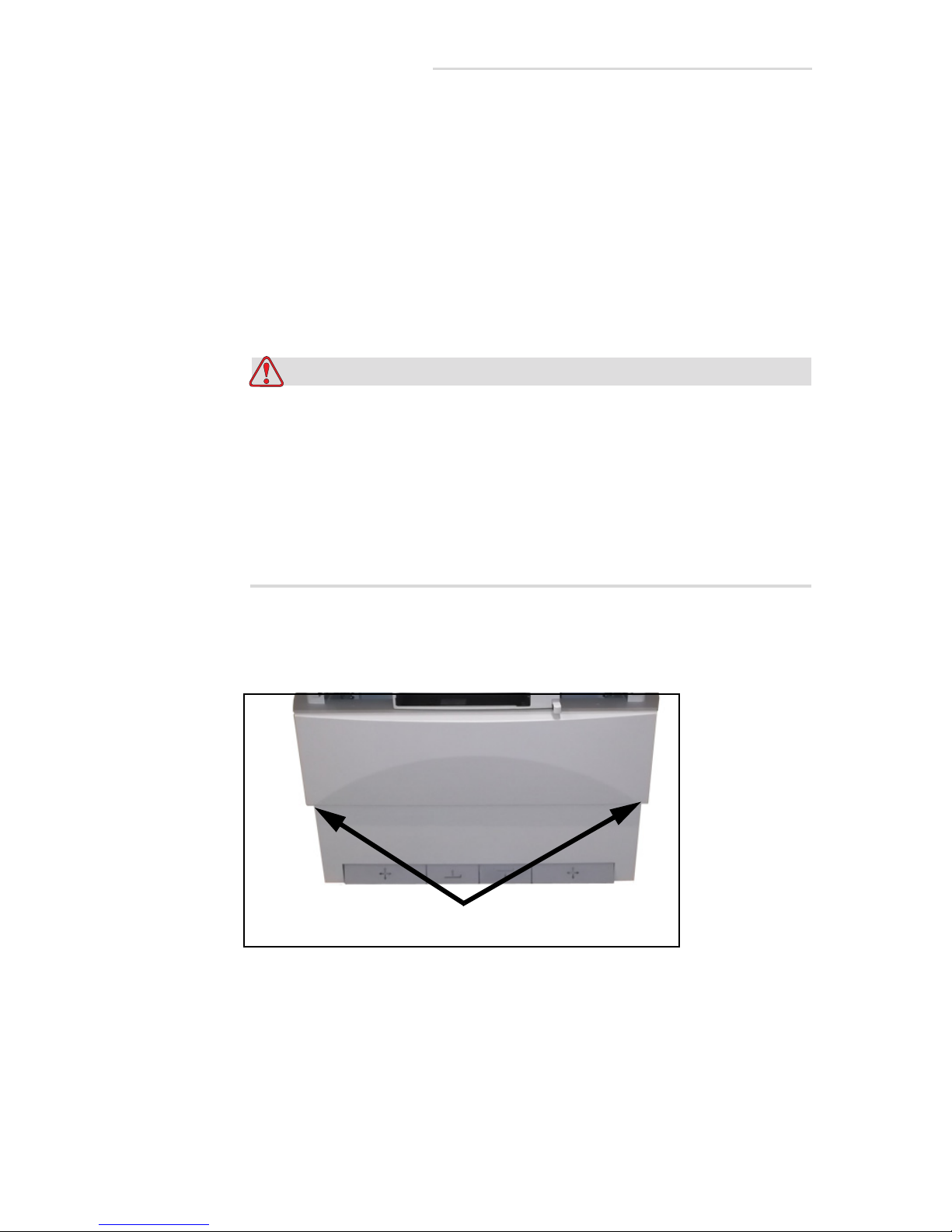
3 Unscrew the upper panel screws (1 in Figure 5-1), tilt panel (2) out,
and lift off from the table.
Figure 5-1. Upper Panel Screws
5-2 5.2 Removing Front Panels
Page 83
1
3
4
2
EV800 Elevating Table Installation, Operation, & Service Manual
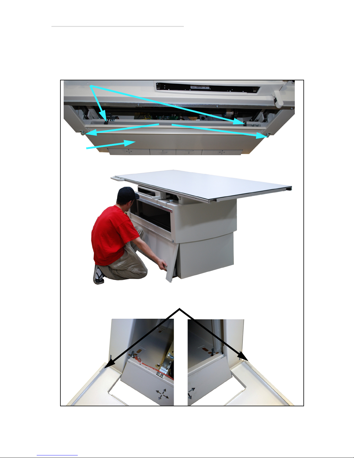
4 Unscrew the two lower panel clamps screws (1 in Figure 5-2), then
remove the lower panhead screws (2).
5 Lift the lower panel (3) up slightly and then pull it out. The bottom of
the lower panel is connected to the table by slots (4) shown below.
Figure 5-2. Lower Panel Clamps
5.2 Removing Front Panels 5-3
Page 84
EV800 Elevating Table Installation, Operation, & Service Manual
Warning
Caution
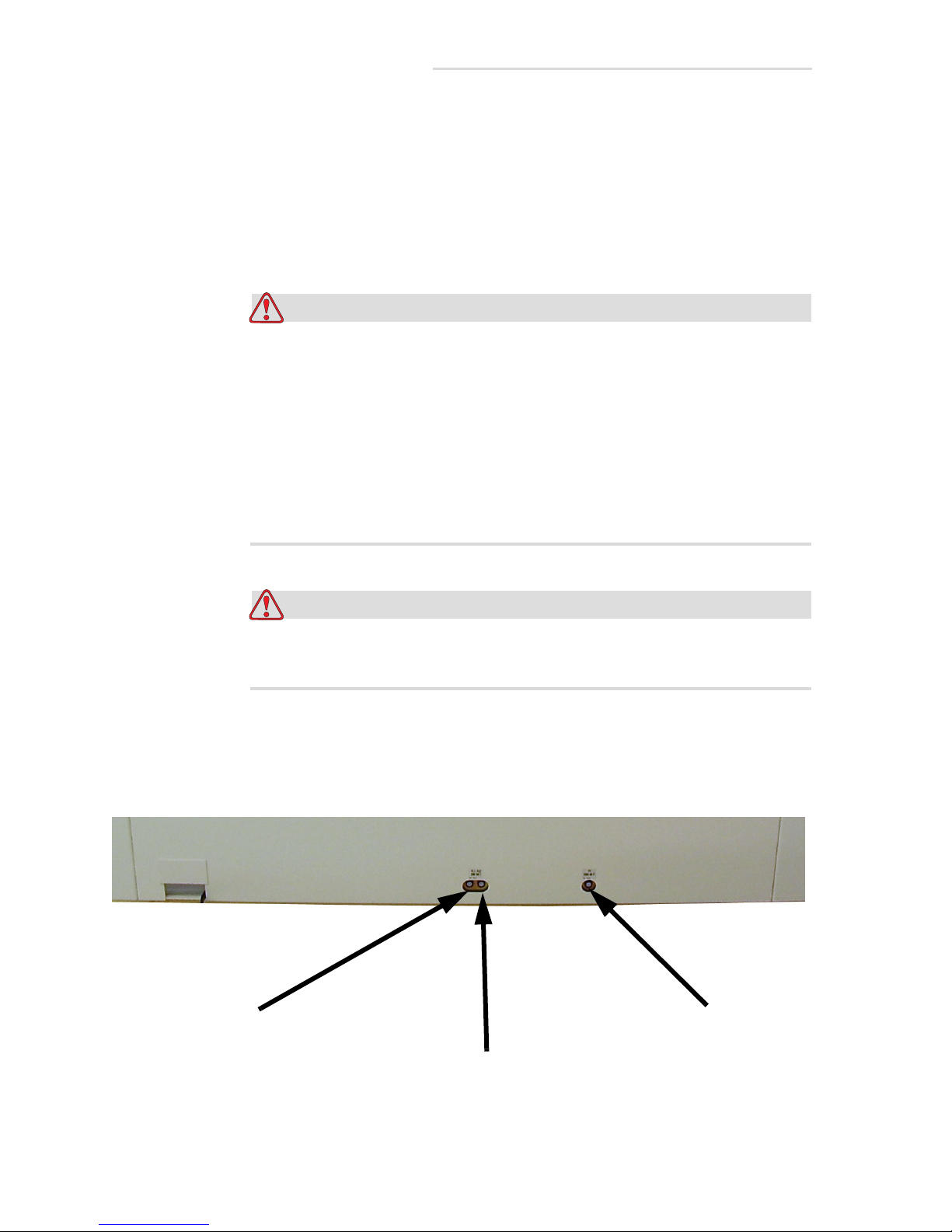
FL2 (Line 2)
FL1 (Line 1)
F1 (Drive Motor)
10 Amp 250V T
10 Amp 250V T
10 Amp 250V T
5.3 Replacing Fuses F1, FL1, & FL2
Tools Required:
• Small flat-tip screwdriver
1 Turn off all power to table and wait five minutes for table’s capacitors
to discharge.
Turn off all electrical power to the table and all its peripheral
equipment (generator, tubestand, etc.) at the power sources before
servicing the table. Also, make sure that the power sources are
locked out and tagged “Equipment Being Serviced” before
servicing the table. Some components inside the table have power
sources other than that of the table, which is why all peripheral
equipment must be turned off; you could get seriously injured if
you not. Wait five minutes after turning power off to work on the
table.
Replace fuses only with same type and rating of fuse or machine
may get damaged.
2 Access to the fuses is on the back to the table’s base. Unscrew the fuse
cap of the faulty fuse and replace the fuse. See figure below for
location and fuse rating.
3 Reverse steps to reassemble.
5-4 5.3 Replacing Fuses F1, FL1, & FL2
Figure 5-3. Fuse Location
Page 85
EV800 Elevating Table Installation, Operation, & Service Manual
Warning
Caution
5.4 Drive Motor Override
Tools Required:
• 3/16” hex wrench
• 9/16” socket and ratchet
• Phillips head screwdriver
• Small/medium flat blade screwdriver
•Hammer
• Large channel-lock pliers or vise grips
In cases where the table is all the way down and has no power, you cannot
gain access to many components that may need to be serviced, because
you will not be able to remove the lower front panel. To raise the table to
allow removal of the lower front panel, perform the following procedure.
1 Turn off all power to the table and wait five minutes for the table’s
capacitors to discharge.
Turn off all electrical power to the table and all its peripheral
equipment (generator, tubestand, etc.) at the power sources before
servicing the table. Also, make sure that the power sources are
locked out and tagged “Equipment Being Serviced” before
servicing the table. Some components inside the table have power
sources other than that of the table, which is why all peripheral
equipment must be turned off; you could get seriously injured if
you not. Wait five minutes after turning power off to work on
table.
Replace the fuses only with the same type and rating of the fuse or
the machine may get damaged.
2 If room dimensions allow, remove the stop bumpers from the end of
table top assembly and carefully remove the table top from the table
frame.
3 If unable to remove the table top it will be necessary to remove the
stop bumpers and slide the top to the head of the table.
5.4 Drive Motor Override 5-5
Page 86
EV800 Elevating Table Installation, Operation, & Service Manual
1
1
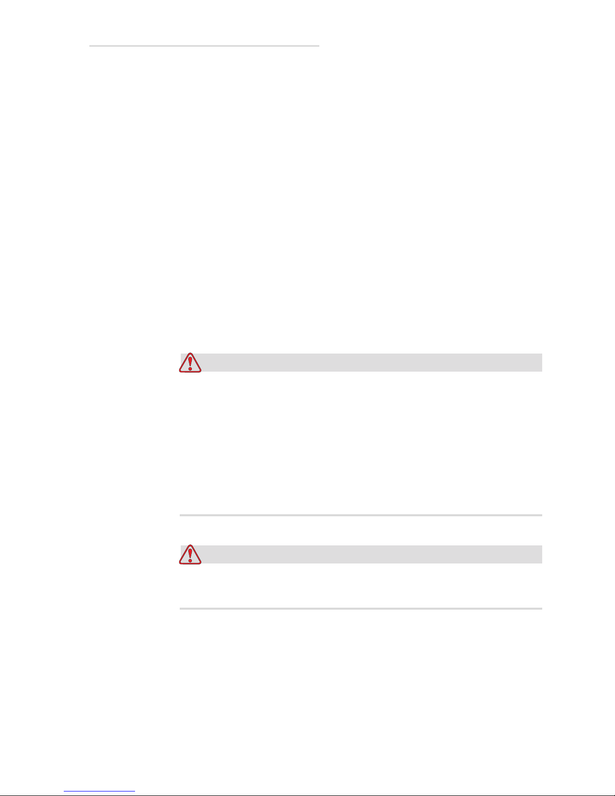
4 At rear of the table, remove the two gearbox access panels (1 in
Figure 5-4).
Figure 5-4. Gearbox Access Panels
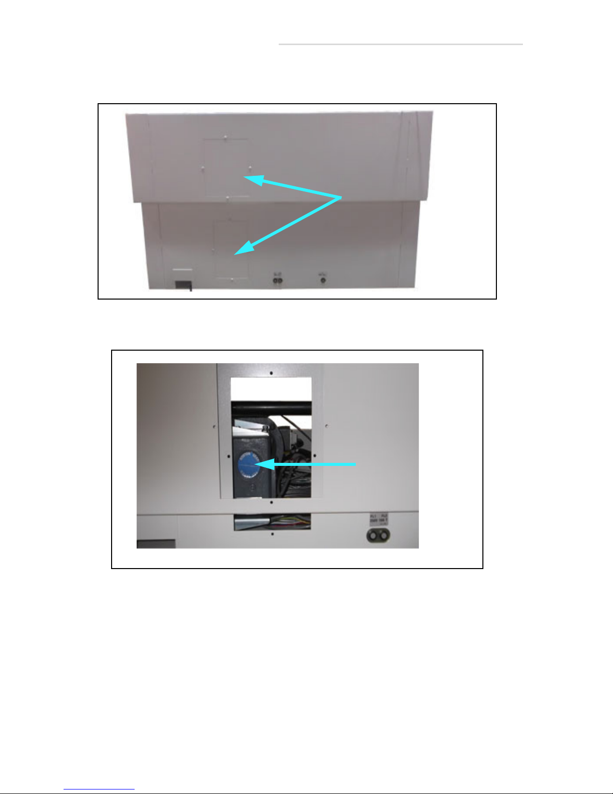
5 The rear of the gearbox should now be visible (1 in Figure 5-5).
Figure 5-5. Gearbox
5-6 5.4 Drive Motor Override
Page 87
EV800 Elevating Table Installation, Operation, & Service Manual
1
1
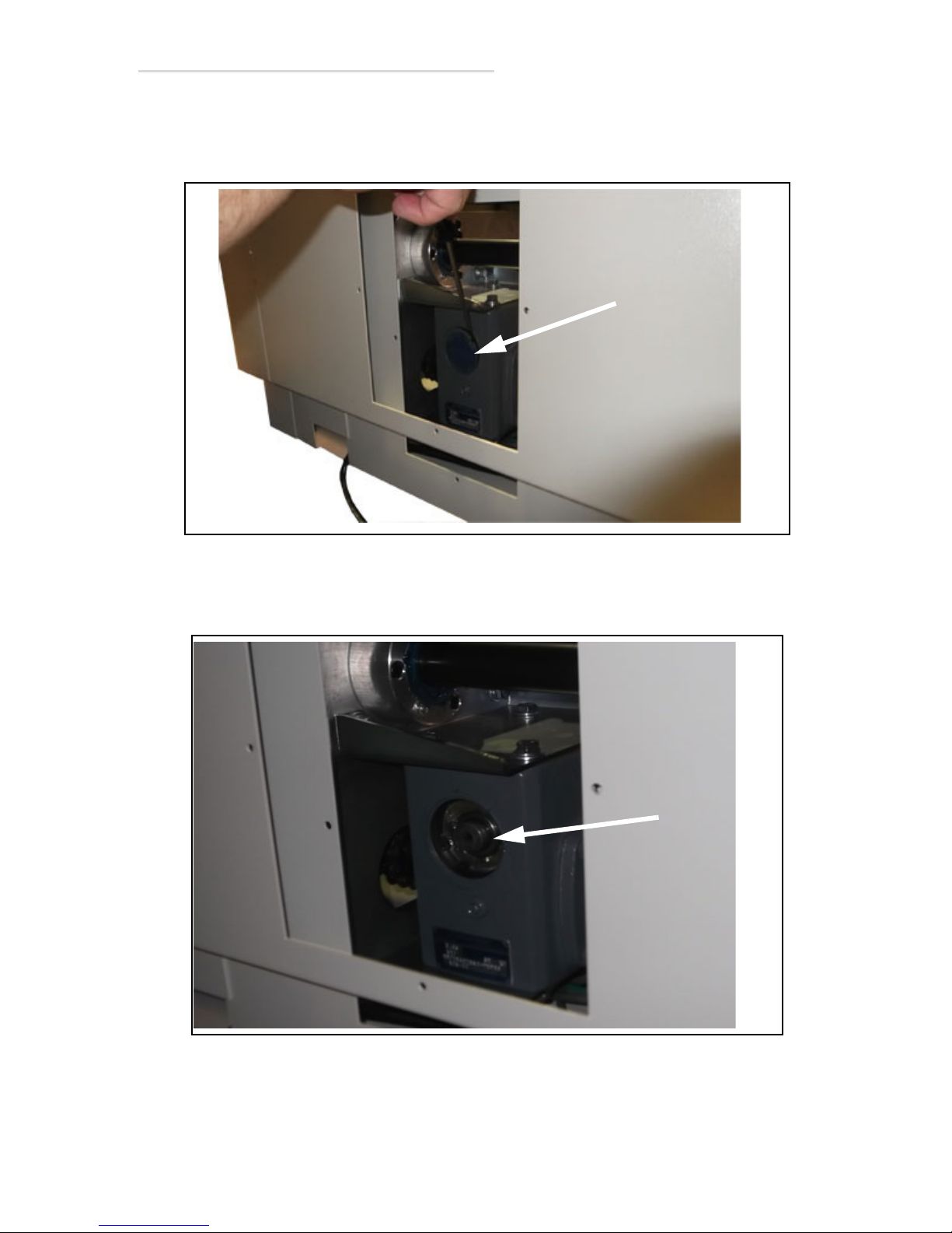
6 It is necessary to remove the grease cap to access the rear hub of the
input shaft. Using a small, flat screwdriver and hammer, carefully pry
off the grease cap (1 in Figure 5-6) and set it aside.
Figure 5-6. Grease Cap
7 Carefully wipe off excess grease from the end of the input shaft (1 in
Figure 5-7).
Figure 5-7. Input shaft
5.4 Drive Motor Override 5-7
Page 88
EV800 Elevating Table Installation, Operation, & Service Manual
1
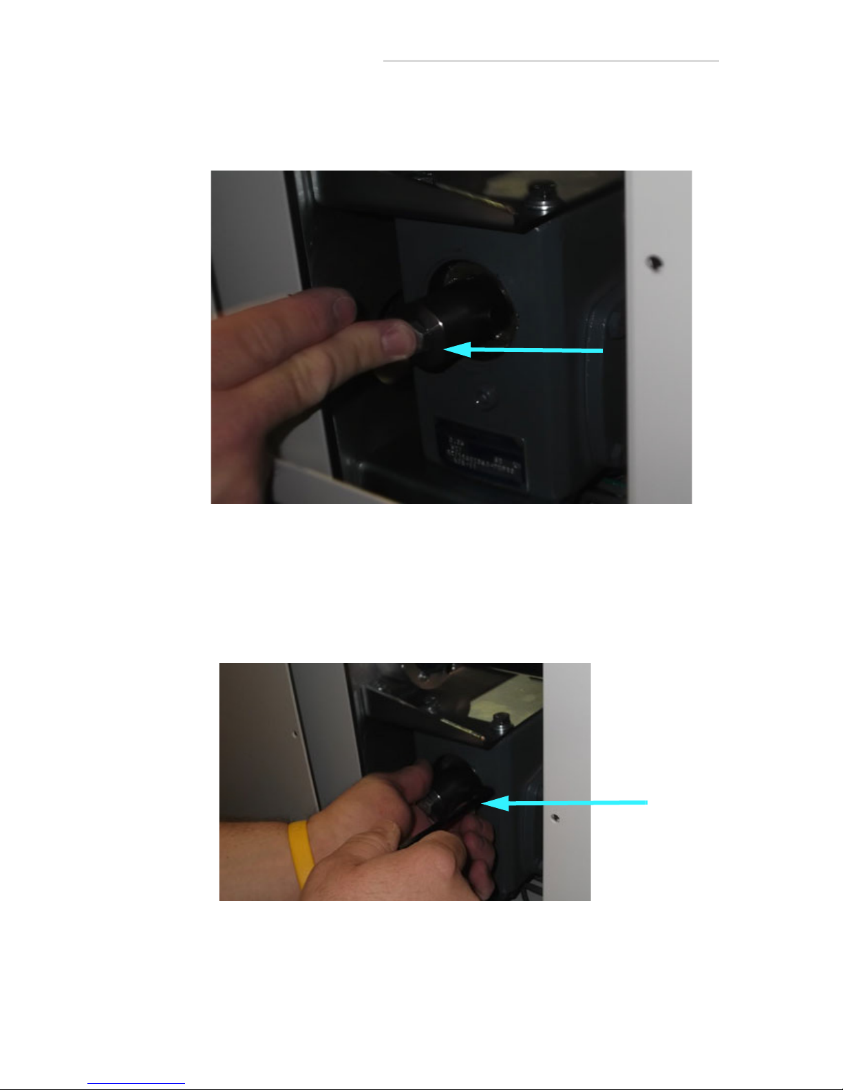
8 Locate the override coupling assembly (112-5557G1) in the table
shipping kit. Place the coupling over the exposed end of the input
shaft as shown (1 in Figure 5-8).
1
Figure 5-8. Override Coupling Assembly
9 Using pliers or vise grips, hold the overrride coupling while securely
tightening the black clamping screw (1 in Fgure 5-9).
Note: A light tap with a hammer can be used to seat the coupling flat on the input
shaft.
5-8 5.4 Drive Motor Override
Figure 5-9. Black Clamping Screw
Page 89
EV800 Elevating Table Installation, Operation, & Service Manual
Warning
1
1
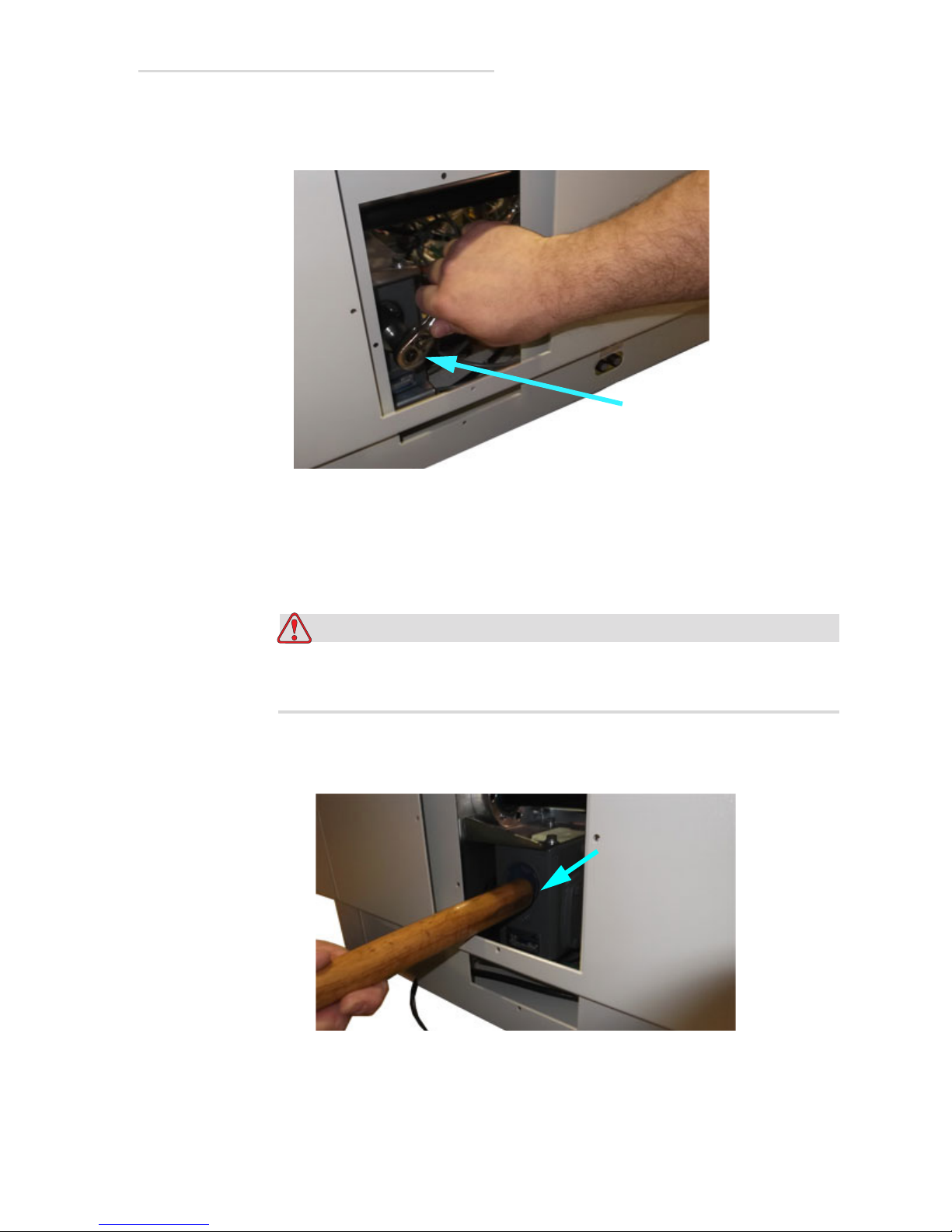
10 Using a 9/16” socket and ratchet (1 in Figure 5-10), the table can now
by manually raised or lowered for service.
Figure 5-10. Socket and Ratchet
Note: Clockwise rotation = raise the table. Counterclockwise rotation = lower
table. The gearbox used in the table is a 60:1 reduction and will require
approximately 16 rotations to raise the table 1”.
Override coupling must be removed from the gearbox prior to any
attempt to return power and operate the table.
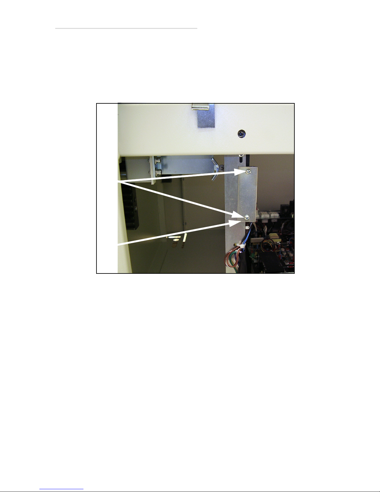
11 Reinstall the grease cap (1 in Figure 5-11). The wooden handle of a
hammer may be used to gently tap back into place. Reinstall access.
covers.
Figure 5-11. Reinstall grease cap
5.4 Drive Motor Override 5-9
Page 90

EV800 Elevating Table Installation, Operation, & Service Manual
Warning
5.5 Adjusting Table Elevation Mid-Point Height
The height at which the table stops at its mid-point (SID height) can be
adjusted according to the following steps.
Tools Required:
• Medium-size phillips screw driver
• Set of hex wrenches
1 Run table to its uppermost position
Turn off all electrical power to the table and all its peripheral
equipment (generator, tubestand, etc.) at the power sources before
servicing the table. Also, make sure that the power sources are
locked out and tagged “Equipment Being Serviced” before
servicing the table. Some components inside the table have power
sources other than that of the table, which is why all peripheral
equipment must be turned off; you could get seriously injured if
you not. Wait five minutes after turning power off to work on
table.
2 Turn off all power to the table and wait five minutes for table’s
capacitors to discharge.
3 Remove front panels according to Section 5.2 Removing “Front
Panels” on page 5-2.
5-10 5.5 Adjusting Table Elevation Mid-Point Height
Page 91
EV800 Elevating Table Installation, Operation, & Service Manual
2
1
4 Loosen the two clamp screws (1 in Figure 5-12), move the plate (2) to
the desired position, and retighten the screws.
5 Test the new mid-table pause position. Readjust as necessary.
6 Reassemble table.
Figure 5-12. Cam Plate Position
5.5 Adjusting Table Elevation Mid-Point Height 5-11
Page 92

EV800 Elevating Table Installation, Operation, & Service Manual
Caution
5.6 Testing & Adjusting Collision Avoidance
Switches
Tools Required:
• 5/16” open-end wrench
• Medium phillips screwdriver
• Set of hex wrenches
Testing Switches
1 Move table top to its leftmost position.
2 Turn on power to the table.
3 Run table to its highest position.
4 Place a stool or other sturdy support under the left end of the table top
as shown in Figure 5-13 on the next page.
5 Place a weight scale on the stool.
Do not exceed 110 lbs (49 Kg) of force in the following step or the
table may get damaged. If the force appears that it will exceed 110
lbs (49 Kg), release the down pedal immediately.
6 Press the down pedal and lower the table until the table top contacts
the scale and the table stops by itself. The force on the scale when the
table stops should be between 90 to 110 lbs (40 to 49 Kg.). If it is not or
if the force exceeds 110lbs (49 Kg), adjust the collision avoidance
switch according to step 10. If it is, go to the next step.
7 Raise table back up.
8 Move table top to its rightmost position.
9 Repeat steps 4-6 for right end of table top.
5-12 5.6 Testing & Adjusting Collision Avoidance Switches
Page 93
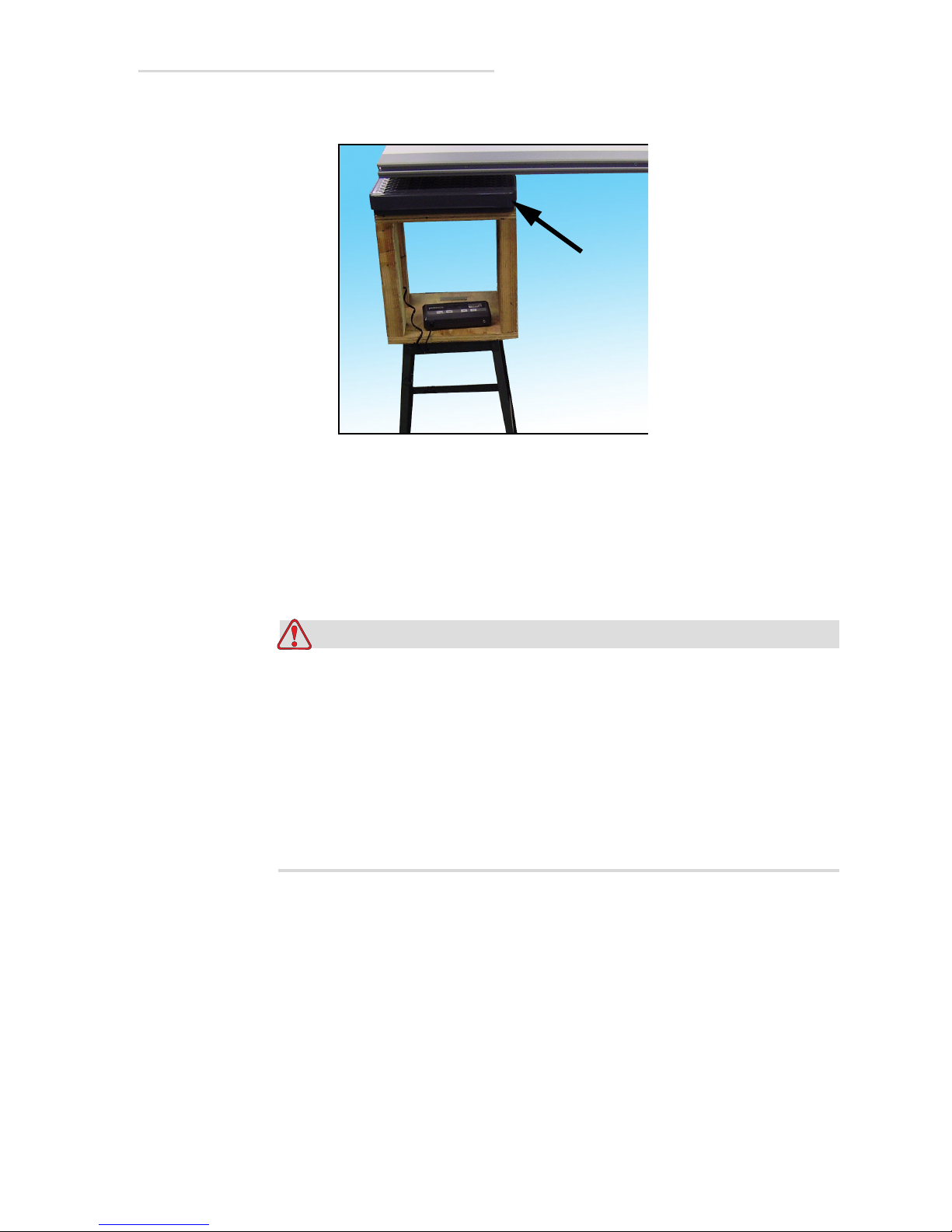
EV800 Elevating Table Installation, Operation, & Service Manual
Warning
Scale
Figure 5-13. Scale & Stool Under Table Top
Adjusting Switches
10 Turn off all power to the table and wait five minutes for the table’s
capacitors to discharge.
Turn off all electrical power to the table and all its peripheral
equipment (generator, tubestand, etc.) at the power sources before
servicing the table. Also, make sure that the power sources are
locked out and tagged “Equipment Being Serviced” before
servicing the table. Some components inside the table have power
sources other than that of the table, which is why all peripheral
equipment must be turned off; you could get seriously injured if
you not. Wait five minutes after turning power off to work on
table.
5.6 Testing & Adjusting Collision Avoidance Switches 5-13
Page 94
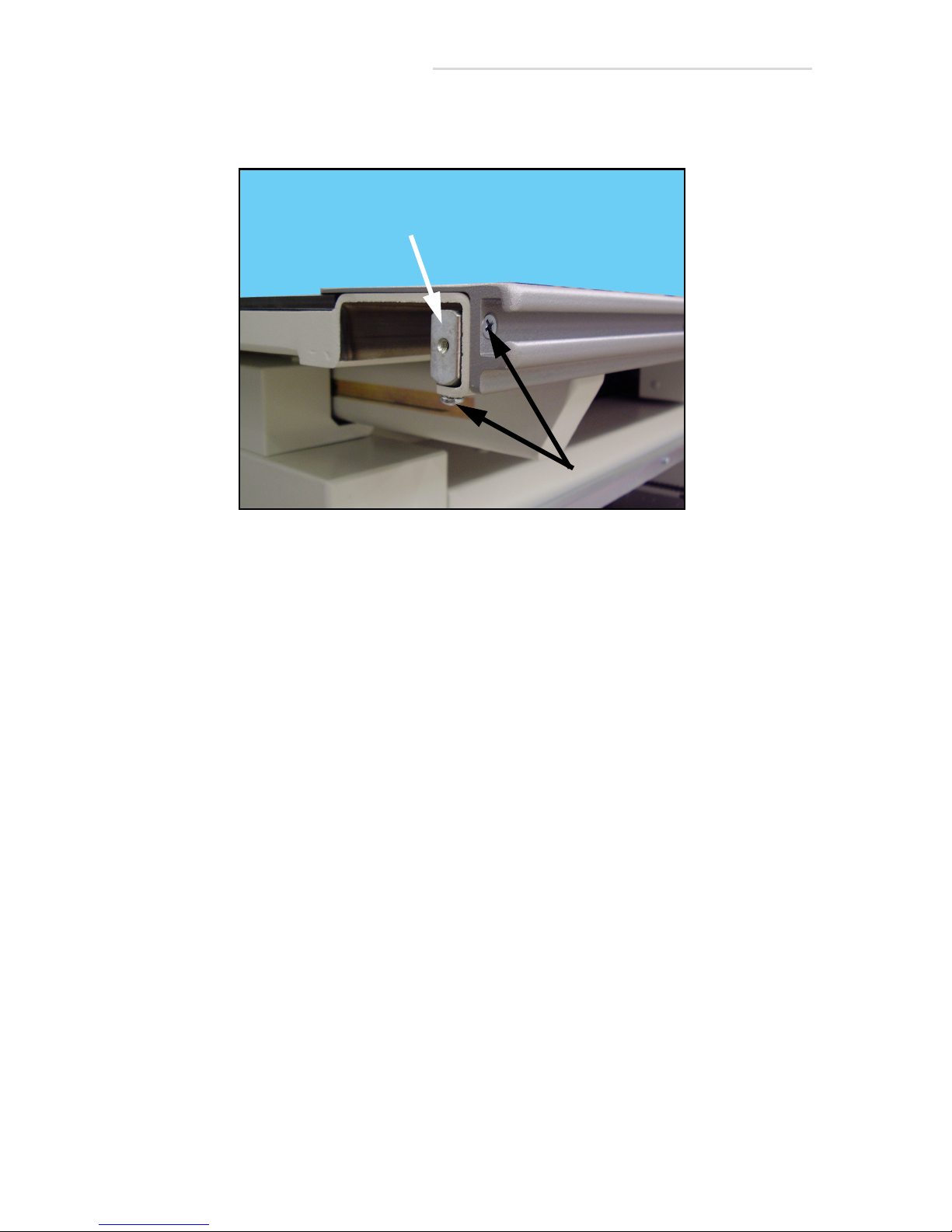
EV800 Elevating Table Installation, Operation, & Service Manual
1
2
11 Unscrew the bumper screws (1 in Figure 5-14) and remove the
bumpers (2) from all four corners of table top.
Figure 5-14. Bumper Removal
5-14 5.6 Testing & Adjusting Collision Avoidance Switches
Page 95
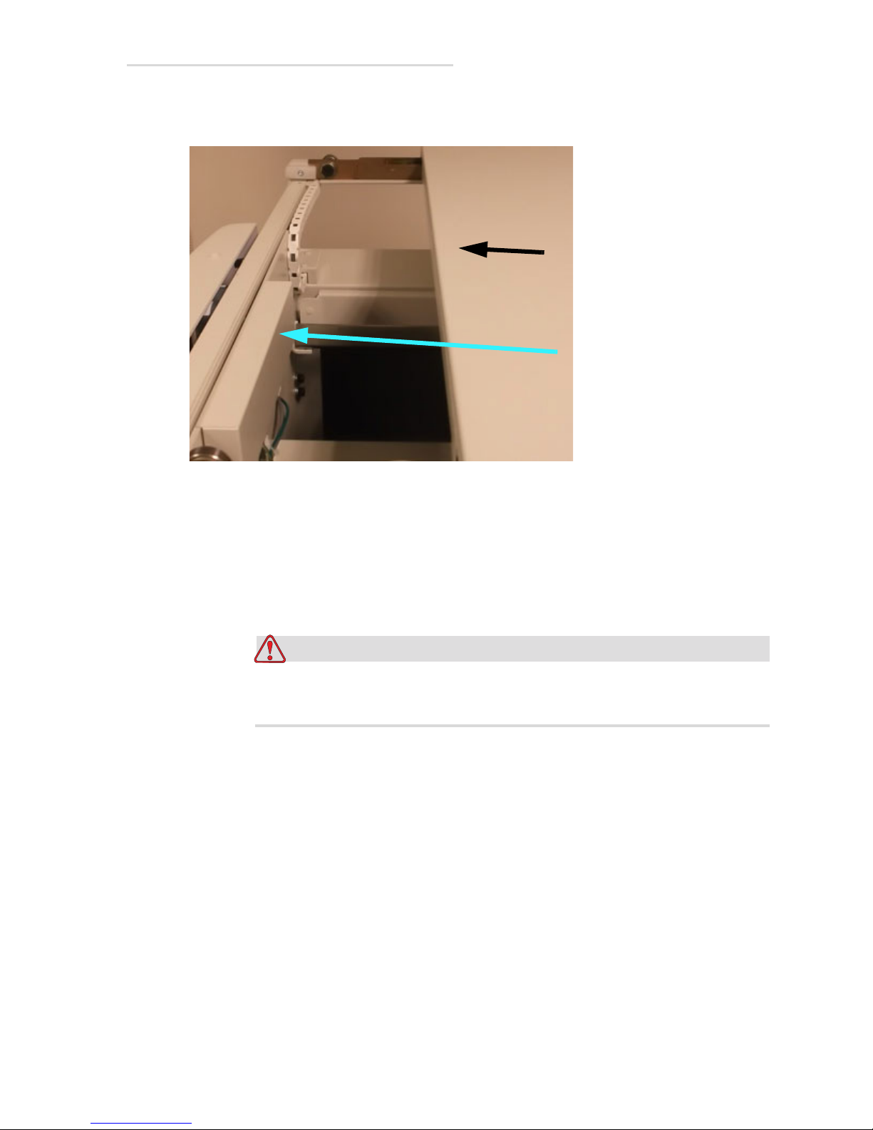
EV800 Elevating Table Installation, Operation, & Service Manual
Caution
2
1
12 Slide the table top (1 in Figure 5-15) and remove cover (2) to expose
switch assembly.
Figure 5-15. Slide Table Top
13 Loosen jam nut (1 in Figure 5-16).
14 Turn adjustment screw (2) in 1/4 turn increments and retest pressure.
Turn it clockwise to reduce table stoppage pressure and
counterclockwise to increase pressure.
Be careful not to adjust the pressure so much that the switch’s arm
(3) rests on the switch (4) or the switch may get damaged.
15 When proper pressure is achieved, tighten the jam nut and repeat the
procedure for the switch on other side of the table.
5.6 Testing & Adjusting Collision Avoidance Switches 5-15
Page 96
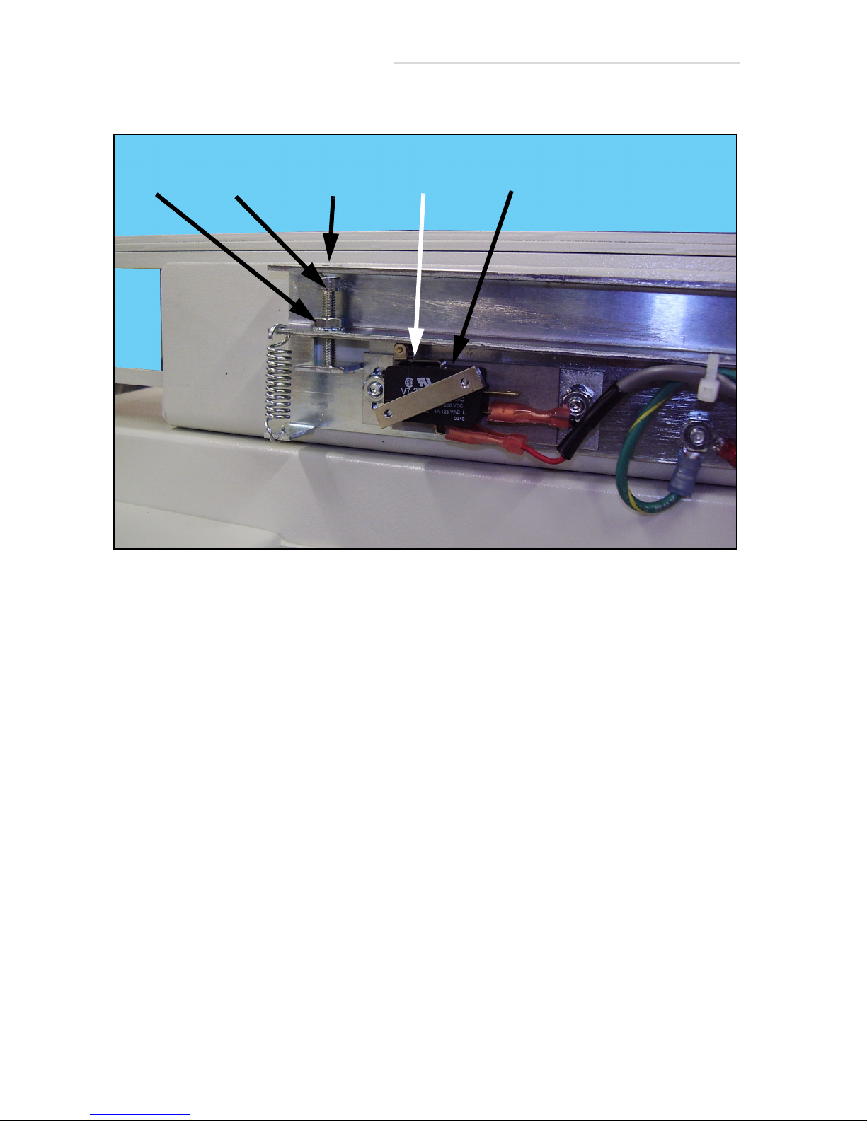
EV800 Elevating Table Installation, Operation, & Service Manual
21
Access
34
Hole
16 Reverse steps to reassemble the table.
Figure 5-16. Pressure Adjustment
5-16 5.6 Testing & Adjusting Collision Avoidance Switches
Page 97
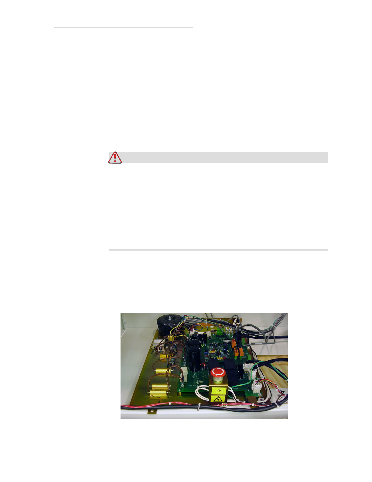
EV800 Elevating Table Installation, Operation, & Service Manual
Warning
5.7 Changing Elevation Restart Mode
The mid-point elevation restart mode of the up and down pedals can be
changed from manual to automatic and vice versa as follows:
Tools Required:
• Set of hex wrenches
• Medium flat-tip screwdriver
•Needle-nose pliers
1 Run table to its uppermost position
Turn off all electrical power to the table and all its peripheral
equipment (generator, tubestand, etc.) at the power sources before
servicing the table. Also, make sure that the power sources are
locked out and tagged “Equipment Being Serviced” before
servicing the table. Some components inside the table have power
sources other than that of the table, which is why all peripheral
equipment must be turned off; you could get seriously injured if
you not. Wait five minutes after turning power off to work on
table.
2 Turn off all power to the table.
3 Remove front panels according to Section 5.2 “Removing Front
Panels” on page 5-2.
Note: The following steps will be performed on the main chassis
which is located on the base of the table as shown below.
Figure 5-17. Main Chassis
5.7 Changing Elevation Restart Mode 5-17
Page 98
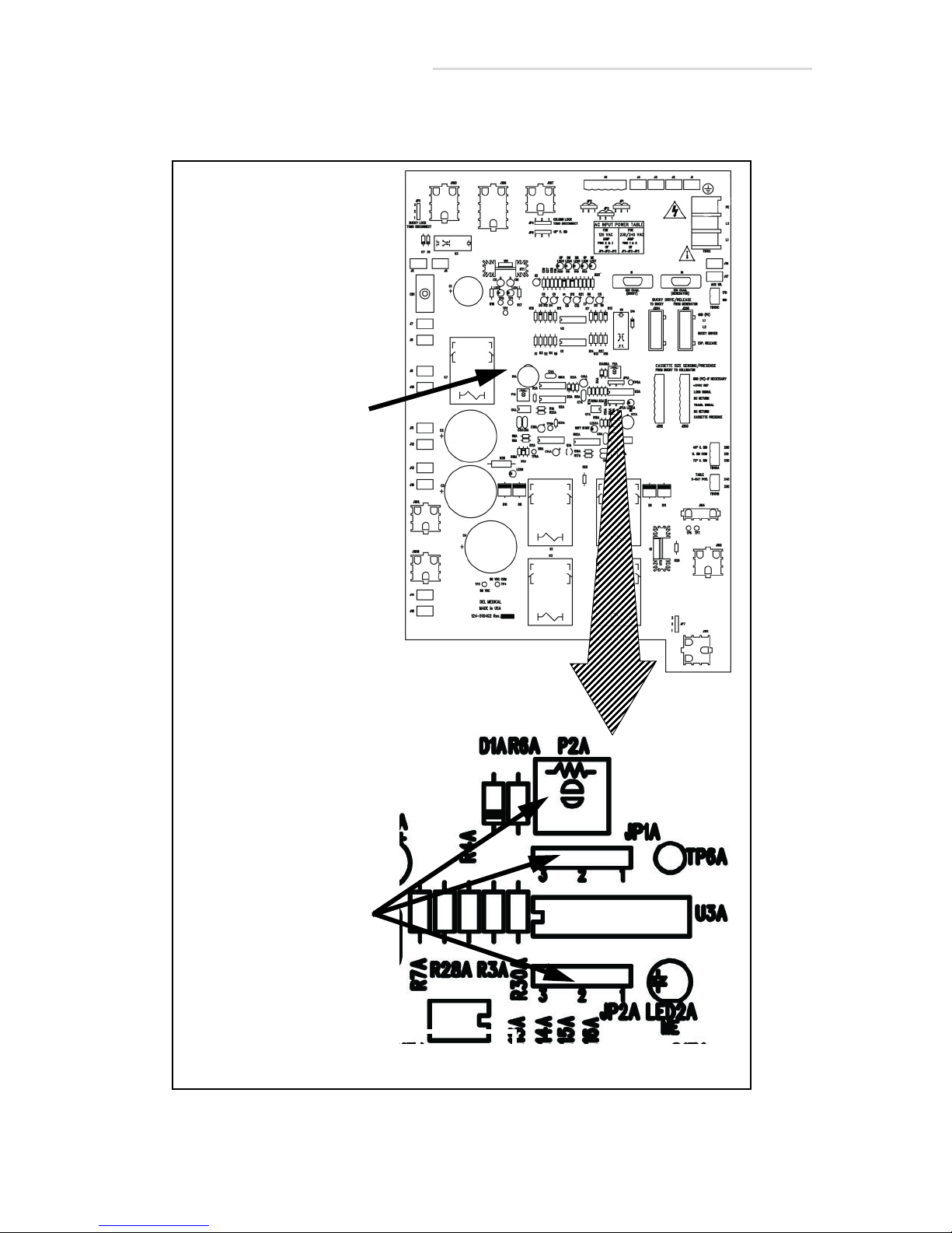
EV800 Elevating Table Installation, Operation, & Service Manual
Restart Mode
Pot & Jumpers
Main Chassis
4 Locate Restart Mode Pot and Jumpers on the motor control board
using figure below. Then go to the next step.
Figure 5-18. Restart Mode Pot & Jumpers
5-18 5.7 Changing Elevation Restart Mode
Page 99
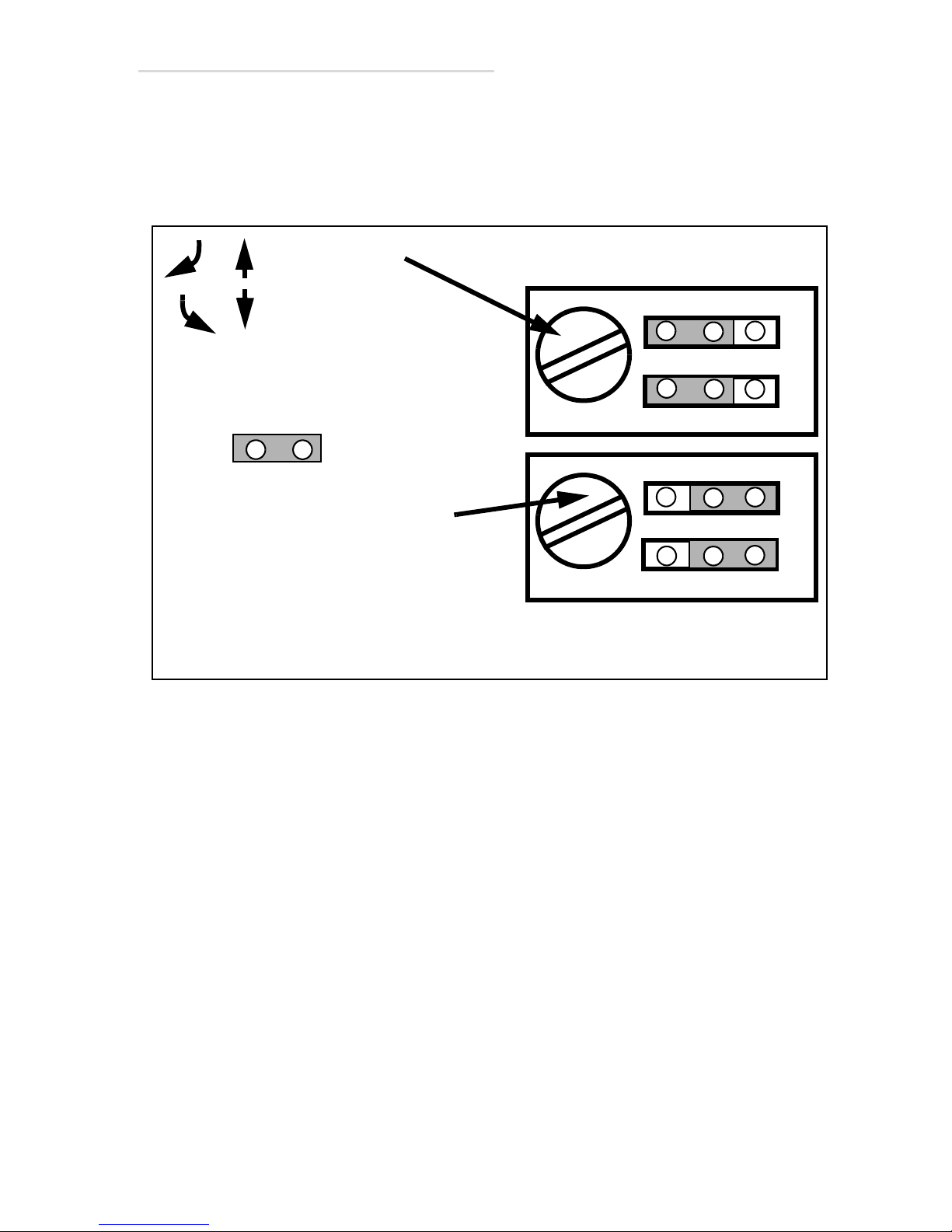
EV800 Elevating Table Installation, Operation, & Service Manual
DETENT
JP1A
JP2A
P2A
DETENT
JP1A
JP2A
P2A
= Jumper
Automatic Restart Mode
Manual Restart Mode
Jumper Positions
Turn pot to
Jumper Positions
=
=
increase or
decrease
delay of
restart
Turning pot in
manual mode
will have no
effect.
5 Set the jumpers to the desired settings as shown in figure below.
6 For automatic mode, set the pot to the desired setting, test delay time,
and readjust as necessary.
7 Reverse steps to reassemble.
Figure 5-19. Elevation Adjustment Pots
5.7 Changing Elevation Restart Mode 5-19
Page 100

EV800 Elevating Table Installation, Operation, & Service Manual
This page is intentionally left blank.
5-20 5.7 Changing Elevation Restart Mode
 Loading...