


Anthem Generator

Anthem Generator
Table of
Contents
Safety
Introduction
Installation, Operation
& Service Manual
Models 30-400, 30-500, 32-500, 40-500, 40-600 and 50-650
Installation
Operation
Periodic
Maintenance
Calibration &
Adjustments
Component
Replacement
FP10-0084.00
P/N 8000-ANTHEM-D
Revision C, May 1, 2010
TroubleShooting
Electrical
Schematics
Illustrated
Parts List
Notes
Copyright 2010, Del Medical Systems. All rights reserved.
This document is the property of Del Medical Systems and contains confidential and proprietary
information owned by Del Medical Systems. Any unauthorized copying, use or disclosure of it
without the prior written permission of Del Medical Systems is strictly prohibited.
Attention: Consult Accompanying Documents - As Applicable
Del Medical Systems Group
50B NorthGary Avenue Phone:1-847-288-7000
Roselle, IL 60172 Fax:1-847-288-7011
USA Toll Free:1-800-800-6006
www.delmedical.com

Table of Contents
Chapter i — Safety Information
Introduction. . . . . . . . . . . . . . . . . . . . . . . . . . . . . . . . . . . . . . . . . . . . . . . . i–1
Statement of Liability. . . . . . . . . . . . . . . . . . . . . . . . . . . . . . . . . . . . . . . . i–2
Definitions . . . . . . . . . . . . . . . . . . . . . . . . . . . . . . . . . . . . . . . . . . . . . . . . . i–3
Safety Conventions Used in this Manual . . . . . . . . . . . . . . . . . . . . . . . i–4
Warning Statements . . . . . . . . . . . . . . . . . . . . . . . . . . . . . . . . . . . . . i–4
Caution Statements. . . . . . . . . . . . . . . . . . . . . . . . . . . . . . . . . . . . . . i–5
Equipment Safety Guidelines . . . . . . . . . . . . . . . . . . . . . . . . . . . . . . . . . i–6
Safety Information . . . . . . . . . . . . . . . . . . . . . . . . . . . . . . . . . . . . . . . . . . i–8
In Case of Malfunction . . . . . . . . . . . . . . . . . . . . . . . . . . . . . . . . . . . i–8
Safety at Maintenance . . . . . . . . . . . . . . . . . . . . . . . . . . . . . . . . . . . . i–8
Radiation Safety . . . . . . . . . . . . . . . . . . . . . . . . . . . . . . . . . . . . . . . . . . . . i–9
Radiation Protection. . . . . . . . . . . . . . . . . . . . . . . . . . . . . . . . . . . . . . . . i–10
Identification Labels. . . . . . . . . . . . . . . . . . . . . . . . . . . . . . . . . . . . . . . . i–12
Generator Labels . . . . . . . . . . . . . . . . . . . . . . . . . . . . . . . . . . . . . . . i–12
Manufacturer’s Responsibility . . . . . . . . . . . . . . . . . . . . . . . . . . . . . . . i–13
Monitoring Personnel . . . . . . . . . . . . . . . . . . . . . . . . . . . . . . . . . . . . . . i–14
Radiation Protection Survey . . . . . . . . . . . . . . . . . . . . . . . . . . . . . . . . . i–15
Hazardous Materials . . . . . . . . . . . . . . . . . . . . . . . . . . . . . . . . . . . . . . . i–16
Applicable Standards. . . . . . . . . . . . . . . . . . . . . . . . . . . . . . . . . . . . . . . i–17
Grounding Information. . . . . . . . . . . . . . . . . . . . . . . . . . . . . . . . . . . . . i–18
Optical fiber components . . . . . . . . . . . . . . . . . . . . . . . . . . . . . . . . . . . i–19
How to handle fiber optic components . . . . . . . . . . . . . . . . . . . . i–19
Chapter ii — Record of Revisions
Revision History . . . . . . . . . . . . . . . . . . . . . . . . . . . . . . . . . . . . . . . . . . . . ii–1
List of Affected Pages . . . . . . . . . . . . . . . . . . . . . . . . . . . . . . . . . . . . . . .ii–1
Chapter 1 — Introduction
Introduction . . . . . . . . . . . . . . . . . . . . . . . . . . . . . . . . . . . . . . . . . . . . . . . 1-1
X-Ray Tube . . . . . . . . . . . . . . . . . . . . . . . . . . . . . . . . . . . . . . . . . . . . . 1-1
Description . . . . . . . . . . . . . . . . . . . . . . . . . . . . . . . . . . . . . . . . . . . . . . . . 1-2
General features . . . . . . . . . . . . . . . . . . . . . . . . . . . . . . . . . . . . . . . . 1-3
Power Requirements . . . . . . . . . . . . . . . . . . . . . . . . . . . . . . . . . . . . 1-3
Options . . . . . . . . . . . . . . . . . . . . . . . . . . . . . . . . . . . . . . . . . . . . . . . . 1-3
Dimensions . . . . . . . . . . . . . . . . . . . . . . . . . . . . . . . . . . . . . . . . . . . . . . . . 1-4
Minimum Space Requirements . . . . . . . . . . . . . . . . . . . . . . . . . . . . . . . 1-7
Specifications . . . . . . . . . . . . . . . . . . . . . . . . . . . . . . . . . . . . . . . . . . . . . . 1-8
1

Anthem Generator Installation, Operation & Service Manual
Configuration: Model Anthem 30-400; 30 kW, 400mA,
single phase . . . . . . . . . . . . . . . . . . . . . . . . . . . . . . . . . . . . . . . . 1-8
Configuration: Model Anthem 30-500; 30 kW, 500mA,
single phase . . . . . . . . . . . . . . . . . . . . . . . . . . . . . . . . . . . . . . . . 1-9
Configuration: Model Anthem 40-500; 40 kW, 500mA,
single phase . . . . . . . . . . . . . . . . . . . . . . . . . . . . . . . . . . . . . . . 1-10
Configuration: Model Anthem 32-500; 32 kW, 500mA,
3-phase . . . . . . . . . . . . . . . . . . . . . . . . . . . . . . . . . . . . . . . . . . . 1-11
Configuration: Model Anthem 40-600; 40 kW, 600mA,
3-phase . . . . . . . . . . . . . . . . . . . . . . . . . . . . . . . . . . . . . . . . . . . 1-12
Configuration: Model Anthem 50-650; 50 kW, 650mA,
3-phase . . . . . . . . . . . . . . . . . . . . . . . . . . . . . . . . . . . . . . . . . . . 1-13
AEC Specifications: . . . . . . . . . . . . . . . . . . . . . . . . . . . . . . . . . . . 1-14
D.H.H.S. Compliance . . . . . . . . . . . . . . . . . . . . . . . . . . . . . . . . . 1-15
Dimensions . . . . . . . . . . . . . . . . . . . . . . . . . . . . . . . . . . . . . . . . . . 1-15
Regulatory Conformance . . . . . . . . . . . . . . . . . . . . . . . . . . . . . . 1-15
System weights . . . . . . . . . . . . . . . . . . . . . . . . . . . . . . . . . . . . . . . . . . . . 1-16
Compatibility listing . . . . . . . . . . . . . . . . . . . . . . . . . . . . . . . . . . . . . . . 1-17
X-ray Tube Assemblies . . . . . . . . . . . . . . . . . . . . . . . . . . . . . . . . 1-17
Abbreviations . . . . . . . . . . . . . . . . . . . . . . . . . . . . . . . . . . . . . . . . . . . . . 1-18
Optional Accessories . . . . . . . . . . . . . . . . . . . . . . . . . . . . . . . . . . . . . . . 1-19
Control Console Wall Mounting Bracket . . . . . . . . . . . . . . . . 1-19
Control Console Floor Stand . . . . . . . . . . . . . . . . . . . . . . . . . . . 1-19
Theory of Operation . . . . . . . . . . . . . . . . . . . . . . . . . . . . . . . . . . . . . . . 1-20
Prep/Prep Ready Cycle . . . . . . . . . . . . . . . . . . . . . . . . . . . . . . . . . 1-20
Exposure Functions . . . . . . . . . . . . . . . . . . . . . . . . . . . . . . . . . . . . . 1-21
kV Control Functions . . . . . . . . . . . . . . . . . . . . . . . . . . . . . . . . . . . 1-21
mA/Filament Control Functions: . . . . . . . . . . . . . . . . . . . . . . . . . 1-22
Rotor Control: . . . . . . . . . . . . . . . . . . . . . . . . . . . . . . . . . . . . . . . . . 1-22
2
Chapter 2 — Installation
Pre-installation . . . . . . . . . . . . . . . . . . . . . . . . . . . . . . . . . . . . . . . . . . . . .2–1
Tools Required . . . . . . . . . . . . . . . . . . . . . . . . . . . . . . . . . . . . . . . . . .2–1
X-ray Room Pre-planning . . . . . . . . . . . . . . . . . . . . . . . . . . . . . . . . .2–1
Minimum Space Requirements . . . . . . . . . . . . . . . . . . . . . . . . . .2–1
Power Requirements . . . . . . . . . . . . . . . . . . . . . . . . . . . . . . . . . . .2–2
Wiring Requirements. . . . . . . . . . . . . . . . . . . . . . . . . . . . . . . . . . .2–3
System Content. . . . . . . . . . . . . . . . . . . . . . . . . . . . . . . . . . . . . . . . . .2–4
Unpacking . . . . . . . . . . . . . . . . . . . . . . . . . . . . . . . . . . . . . . . . . . . . . .2–4
Installation . . . . . . . . . . . . . . . . . . . . . . . . . . . . . . . . . . . . . . . . . . . . . . . . .2–5
Cable Index . . . . . . . . . . . . . . . . . . . . . . . . . . . . . . . . . . . . . . . . . . . . .2–6
Cable Index Notes . . . . . . . . . . . . . . . . . . . . . . . . . . . . . . . . . . . . .2–7
Connection of Incoming Main Power Cable . . . . . . . . . . . . . . . . .2–8
For Single Phase Generators . . . . . . . . . . . . . . . . . . . . . . . . . . . . .2–8

Anthem Generator Installation, Operation & Service Manual
For 3-phase Generators . . . . . . . . . . . . . . . . . . . . . . . . . . . . . . . . 2–11
Connecting the generator to other x-ray room components . . . 2–14
Connecting Tube Rotor Cable and Image Receptor
Cables to the Generator. . . . . . . . . . . . . . . . . . . . . . . . . . . . . . 2–16
Wall Bucky Connections . . . . . . . . . . . . . . . . . . . . . . . . . . . . . . . 2–17
Table Bucky Connections . . . . . . . . . . . . . . . . . . . . . . . . . . . . . . 2–18
Tube Rotor Connections . . . . . . . . . . . . . . . . . . . . . . . . . . . . . . . 2–19
Connecting Collimator to the Generator . . . . . . . . . . . . . . . . . 2–20
Connecting Table and/or Wallstand Locks
Power to the Generator . . . . . . . . . . . . . . . . . . . . . . . . . . . . . . 2–22
Collimator and Door Interlock. . . . . . . . . . . . . . . . . . . . . . . . . . 2–24
Connecting a Room-In-Use Indicator Light Circuit . . . . . . . . 2–27
Connecting the Control Console . . . . . . . . . . . . . . . . . . . . . . . . 2–28
Connecting the HT Cables to the Generator . . . . . . . . . . . . . . 2–29
Generator Start Up Operational Tests And Installation Set Up . . . 2–32
Test Equipment Required. . . . . . . . . . . . . . . . . . . . . . . . . . . . . . . . 2–32
Inspection of High Tension Transformer . . . . . . . . . . . . . . . . . . . 2–33
Inspection of Power Module . . . . . . . . . . . . . . . . . . . . . . . . . . . . . 2–33
Inspection of Controller . . . . . . . . . . . . . . . . . . . . . . . . . . . . . . . . . 2–34
Operational Testing . . . . . . . . . . . . . . . . . . . . . . . . . . . . . . . . . . . . . 2–35
Verify X-Ray Safety Relay Function . . . . . . . . . . . . . . . . . . . . . . . 2–41
Programming the Default System Configuration Menu . . . . . . 2–42
Power Derating . . . . . . . . . . . . . . . . . . . . . . . . . . . . . . . . . . . . . . 2–43
X Ray Tube Alternatives . . . . . . . . . . . . . . . . . . . . . . . . . . . . . . . 2–44
Perform Default User Screen setup. . . . . . . . . . . . . . . . . . . . . . 2–45
Installing the Del APR Utility Software . . . . . . . . . . . . . . . . . . . . 2–46
Necessary Hardware . . . . . . . . . . . . . . . . . . . . . . . . . . . . . . . . . . 2–46
Installation . . . . . . . . . . . . . . . . . . . . . . . . . . . . . . . . . . . . . . . . . . 2–46
Initial Calibration . . . . . . . . . . . . . . . . . . . . . . . . . . . . . . . . . . . . . . . 2–48
Chapter 3 — Operation
Introduction . . . . . . . . . . . . . . . . . . . . . . . . . . . . . . . . . . . . . . . . . . . . . . . 3-1
Safety Precautions . . . . . . . . . . . . . . . . . . . . . . . . . . . . . . . . . . . . . . . . . . 3-2
Operator Control Console . . . . . . . . . . . . . . . . . . . . . . . . . . . . . . . . . . . 3-3
Anthem Control Console Description . . . . . . . . . . . . . . . . . . . . . . 3-4
Rotational Knob . . . . . . . . . . . . . . . . . . . . . . . . . . . . . . . . . . . . . . . . 3-4
Prep and Expose buttons . . . . . . . . . . . . . . . . . . . . . . . . . . . . . . . . . 3-4
Multi Function Buttons . . . . . . . . . . . . . . . . . . . . . . . . . . . . . . . . . . 3-5
Symbols/text showing on top of the display . . . . . . . . . . . . . . 3-5
Symbols showing to the left side of the display . . . . . . . . . . . . 3-6
Symbols showing at the bottom of the display . . . . . . . . . . . . 3-6
Power On/Off Procedure . . . . . . . . . . . . . . . . . . . . . . . . . . . . . . . . . . . . 3-8
To Power Up The Anthem Generator: . . . . . . . . . . . . . . . . . . . . . . 3-8
To Power Down the Anthem Generator: . . . . . . . . . . . . . . . . . . . 3-8
3

Anthem Generator Installation, Operation & Service Manual
Operating Modes . . . . . . . . . . . . . . . . . . . . . . . . . . . . . . . . . . . . . . . . . . . 3-9
Manual Mode (Two or Three Point Mode) . . . . . . . . . . . . . . . . . . 3-9
Two Point Mode . . . . . . . . . . . . . . . . . . . . . . . . . . . . . . . . . . . . . . 3-9
Three Point Mode . . . . . . . . . . . . . . . . . . . . . . . . . . . . . . . . . . . . . .3- 9
Manual Mode Selection . . . . . . . . . . . . . . . . . . . . . . . . . . . . . . . 3-10
APR - Anatomically Programmable Radiography . . . . . . . . . . . 3-11
APR Mode Selection . . . . . . . . . . . . . . . . . . . . . . . . . . . . . . . . . . 3-11
Change and Save APR Techniques . . . . . . . . . . . . . . . . . . . . . . 3-13
Standard List of Anatomical Regions and Views . . . . . . . . . . 3-13
AEC – Automatic Exposure Control . . . . . . . . . . . . . . . . . . . . . . . 3-14
AEC Mode Selection . . . . . . . . . . . . . . . . . . . . . . . . . . . . . . . . . . 3-14
Setting Default Startup Parameters . . . . . . . . . . . . . . . . . . . . . . . . . . . 3-16
Taking Exposure . . . . . . . . . . . . . . . . . . . . . . . . . . . . . . . . . . . . . . . . . . 3-17
Prep and Expose in Two Point Manual Mode . . . . . . . . . . . . . . 3-17
Daily X-Ray Tube Seasoning Procedure . . . . . . . . . . . . . . . . . 3-17
X Ray Tube Anode Heat Display . . . . . . . . . . . . . . . . . . . . . . . 3-17
To make an exposure . . . . . . . . . . . . . . . . . . . . . . . . . . . . . . . . . 3-17
Fault Indication . . . . . . . . . . . . . . . . . . . . . . . . . . . . . . . . . . . . . . 3-17
Prep and Expose in Three Point Manual Mode . . . . . . . . . . . . . 3-18
Daily X-Ray Tube Seasoning Procedure . . . . . . . . . . . . . . . . . 3-18
X Ray Tube Anode Heat Display . . . . . . . . . . . . . . . . . . . . . . . 3-18
To make an exposure . . . . . . . . . . . . . . . . . . . . . . . . . . . . . . . . . 3-18
Fault Indication . . . . . . . . . . . . . . . . . . . . . . . . . . . . . . . . . . . . . . 3-18
Prep and Expose in APR Mode . . . . . . . . . . . . . . . . . . . . . . . . . . . 3-19
Daily X-Ray Tube Seasoning Procedure . . . . . . . . . . . . . . . . . 3-19
X Ray Tube Anode Heat Display . . . . . . . . . . . . . . . . . . . . . . . 3-19
To make an exposure . . . . . . . . . . . . . . . . . . . . . . . . . . . . . . . . . 3-19
Fault Indication . . . . . . . . . . . . . . . . . . . . . . . . . . . . . . . . . . . . . . 3-19
Prep and Expose in AEC Mode . . . . . . . . . . . . . . . . . . . . . . . . . . . 3-20
Daily X-Ray Tube Seasoning Procedure . . . . . . . . . . . . . . . . . 3-20
X Ray Tube Anode Heat Display . . . . . . . . . . . . . . . . . . . . . . . 3-20
To make an exposure . . . . . . . . . . . . . . . . . . . . . . . . . . . . . . . . . 3-20
Fault Indication . . . . . . . . . . . . . . . . . . . . . . . . . . . . . . . . . . . . . . 3-20
Generator Exposure Tables . . . . . . . . . . . . . . . . . . . . . . . . . . . . . . . . . . 3-21
Specification . . . . . . . . . . . . . . . . . . . . . . . . . . . . . . . . . . . . . . . . . . . . . . 3-25
Configuration: Model Anthem 30-400; 30 kW, 400mA,
single phase . . . . . . . . . . . . . . . . . . . . . . . . . . . . . . . . . . . . . . . 3-25
Configuration: Model Anthem 30-500; 30 kW, 500mA,
single phase . . . . . . . . . . . . . . . . . . . . . . . . . . . . . . . . . . . . . . . 3-26
Configuration: Model Anthem 40-500; 40 kW, 500mA,
single phase . . . . . . . . . . . . . . . . . . . . . . . . . . . . . . . . . . . . . . . 3-27
Configuration: Model Anthem 32-500; 32 kW, 500mA,
3-phase . . . . . . . . . . . . . . . . . . . . . . . . . . . . . . . . . . . . . . . . . . . 3-28
Configuration: Model Anthem 40-600; 40 kW, 600mA,
3-phase . . . . . . . . . . . . . . . . . . . . . . . . . . . . . . . . . . . . . . . . . . . 3-29
Configuration: Model Anthem 50-650; 50 kW, 650mA,
3-phase . . . . . . . . . . . . . . . . . . . . . . . . . . . . . . . . . . . . . . . . . . . 3-30
AEC Specifications: . . . . . . . . . . . . . . . . . . . . . . . . . . . . . . . . . . . 3-31
4

Anthem Generator Installation, Operation & Service Manual
Chapter 4 — Periodic Maintenance
Periodic Maintenance Schedule . . . . . . . . . . . . . . . . . . . . . . . . . . . . . . . 4–1
Discharge procedure . . . . . . . . . . . . . . . . . . . . . . . . . . . . . . . . . . . . . 4–2
Maintenance Schedule. . . . . . . . . . . . . . . . . . . . . . . . . . . . . . . . . . . . 4–7
Cleaning External Surfaces . . . . . . . . . . . . . . . . . . . . . . . . . . . . . . . . . . . 4–8
Tools Required . . . . . . . . . . . . . . . . . . . . . . . . . . . . . . . . . . . . . . . . 4–8
Checking Electrical Cabling . . . . . . . . . . . . . . . . . . . . . . . . . . . . . . . . . 4–10
Tools Required . . . . . . . . . . . . . . . . . . . . . . . . . . . . . . . . . . . . . . . 4–10
Inspecting and Re-grease HT Cables. . . . . . . . . . . . . . . . . . . . . . . . . . 4–11
Tools Required . . . . . . . . . . . . . . . . . . . . . . . . . . . . . . . . . . . . . . . 4–11
Verifying Tube Insert. . . . . . . . . . . . . . . . . . . . . . . . . . . . . . . . . . . . . . . 4–12
Tools Required . . . . . . . . . . . . . . . . . . . . . . . . . . . . . . . . . . . . . . . 4–12
Inspecting Connections . . . . . . . . . . . . . . . . . . . . . . . . . . . . . . . . . . . . . 4–13
Tools Required . . . . . . . . . . . . . . . . . . . . . . . . . . . . . . . . . . . . . . . 4–13
Verifying Accuracy of kV, mAs and mA . . . . . . . . . . . . . . . . . . . . . . 4–14
Tools Required . . . . . . . . . . . . . . . . . . . . . . . . . . . . . . . . . . . . . . . 4–14
Oscilloscope settings . . . . . . . . . . . . . . . . . . . . . . . . . . . . . . . . . . 4–14
Dynalyser display settings . . . . . . . . . . . . . . . . . . . . . . . . . . . . . 4–15
Inspecting Electromechanical Contactors. . . . . . . . . . . . . . . . . . . . . . 4–16
Tools Required . . . . . . . . . . . . . . . . . . . . . . . . . . . . . . . . . . . . . . . 4–16
Checking High Voltage Transformer . . . . . . . . . . . . . . . . . . . . . . . . . 4–17
Tools Required . . . . . . . . . . . . . . . . . . . . . . . . . . . . . . . . . . . . . . . 4–17
Checking Audible and Visual Exposure Indicators . . . . . . . . . . . . . 4–18
Tools Required . . . . . . . . . . . . . . . . . . . . . . . . . . . . . . . . . . . . . . . 4–18
Checking Fasteners for Tightness . . . . . . . . . . . . . . . . . . . . . . . . . . . . 4–19
Tools Required . . . . . . . . . . . . . . . . . . . . . . . . . . . . . . . . . . . . . . . 4–19
Chapter 5 — Calibration and Adjustments
Introduction. . . . . . . . . . . . . . . . . . . . . . . . . . . . . . . . . . . . . . . . . . . . . . . . 5–1
Calibration Procedure . . . . . . . . . . . . . . . . . . . . . . . . . . . . . . . . . . . . . . . 5–2
Preparations . . . . . . . . . . . . . . . . . . . . . . . . . . . . . . . . . . . . . . . . . . . . 5–2
Test Equipment Required . . . . . . . . . . . . . . . . . . . . . . . . . . . . . . . 5–2
Connecting mAs-meter . . . . . . . . . . . . . . . . . . . . . . . . . . . . . . . . . 5–3
Oscilloscope settings . . . . . . . . . . . . . . . . . . . . . . . . . . . . . . . . . . . 5–6
Dynalyser display settings . . . . . . . . . . . . . . . . . . . . . . . . . . . . . . 5–6
Initial Exposure . . . . . . . . . . . . . . . . . . . . . . . . . . . . . . . . . . . . . . . 5–7
Enter Service Mode . . . . . . . . . . . . . . . . . . . . . . . . . . . . . . . . . . . . . . 5–7
Calibration of mA . . . . . . . . . . . . . . . . . . . . . . . . . . . . . . . . . . . . . . . 5–8
Calibration of kV . . . . . . . . . . . . . . . . . . . . . . . . . . . . . . . . . . . . . . . 5–10
Pre-Heat. . . . . . . . . . . . . . . . . . . . . . . . . . . . . . . . . . . . . . . . . . . . . . . 5–11
Managing the APR database. . . . . . . . . . . . . . . . . . . . . . . . . . . . . . . . . 5–13
Necessary Hardware . . . . . . . . . . . . . . . . . . . . . . . . . . . . . . . . . . 5–13
Operating the program . . . . . . . . . . . . . . . . . . . . . . . . . . . . . . . . 5–13
Download data from the Control Console using
5

Anthem Generator Installation, Operation & Service Manual
either a DB9 cable or an SD memory card . . . . . . . . . . . . . .5–13
Downloading Configuration Data . . . . . . . . . . . . . . . . . . . . . . . . .5–15
Downloading configuration data from the Operator’s
Console using a DB9 cable . . . . . . . . . . . . . . . . . . . . . . . . . . .5–15
Downloading configuration data using an SD memory card 5–16
Adjust the APR Database . . . . . . . . . . . . . . . . . . . . . . . . . . . . . . . .5–18
Did the column header turn red when you changed
a parameter? . . . . . . . . . . . . . . . . . . . . . . . . . . . . . . . . . . . . . . .5–19
Creating New Anatomical Views . . . . . . . . . . . . . . . . . . . . . . . . .5–19
Uploading Modified APR Files using a DB9 Cable. . . . . . . . . . . 5–20
Uploading Modified APR Files using an SD Memory Card . . . 5–20
Error Messages . . . . . . . . . . . . . . . . . . . . . . . . . . . . . . . . . . . . . . . . .5–22
Interface Cable. . . . . . . . . . . . . . . . . . . . . . . . . . . . . . . . . . . . . . . . . . . . .5–23
Calibration Procedure . . . . . . . . . . . . . . . . . . . . . . . . . . . . . . . . . . . . . . 5-24
Verification of the Generator Backup mAs and Reset Function: . . . 5-39
Verification of the AEC Safety Stop Function . . . . . . . . . . . . . . . . . . 5-39
(No Ramp, Bad ION Chamber
Chapter 6 — Component Replacement
Introduction . . . . . . . . . . . . . . . . . . . . . . . . . . . . . . . . . . . . . . . . . . . . . . . .6–1
Discharge procedure. . . . . . . . . . . . . . . . . . . . . . . . . . . . . . . . . . . . . . . . .6–2
Removing Front Panel . . . . . . . . . . . . . . . . . . . . . . . . . . . . . . . . . . . . . . . 6-3
Removing Upper Cabinet Cover . . . . . . . . . . . . . . . . . . . . . . . . . . . . . . 6-4
Replacing Fuses on Power Relay Board . . . . . . . . . . . . . . . . . . . . . . . . 6-6
Replacing Transformers . . . . . . . . . . . . . . . . . . . . . . . . . . . . . . . . . . . . . 6-9
Single-phase Generators . . . . . . . . . . . . . . . . . . . . . . . . . . . . . . . . . . 6-9
Replace Line Match Transformer (Single-phase Generator) . 6-10
Replace Isolation Transformer (Single-phase Generator) . . . 6-11
3-phase Generators . . . . . . . . . . . . . . . . . . . . . . . . . . . . . . . . . . . . . 6-12
Replace Line Match Transformer(s) (3-phase Generator) . . . 6-13
Replace Isolation Transformer (3-phase Generator) . . . . . . . 6-14
Replacing Boards . . . . . . . . . . . . . . . . . . . . . . . . . . . . . . . . . . . . . . . . . . 6-16
Replacing the Filament Board (124-5131G1) . . . . . . . . . . . . . . . . 6-17
Replacing the Power Relay Board (124-5136G1) . . . . . . . . . . . . . 6-18
Replacing the Main Control Board (124-5132G1) . . . . . . . . . . . . 6-19
Replacing the IPM Driver Board (124-5130G1) . . . . . . . . . . . . . . 6-20
Replacing the Room Interface Board (124-5134G1) . . . . . . . . . . 6-21
Verification of AEC Safety . . . . . . . . . . . . . . . . . . . . . . . . . . . . . . . 6-43
Verification of Generator Backup mAs and Reset Function . . . 6-43
Verification of the AEC Stop Function . . . . . . . . . . . . . . . . . . . . . 6-43
6

Anthem Generator Installation, Operation & Service Manual
Chapter 7 — Troubleshooting
Introduction. . . . . . . . . . . . . . . . . . . . . . . . . . . . . . . . . . . . . . . . . . . . . . . . 7–1
Discharge procedure . . . . . . . . . . . . . . . . . . . . . . . . . . . . . . . . . . . . . . . . 7–2
Troubleshooting Index & Charts . . . . . . . . . . . . . . . . . . . . . . . . . . . . . 7–63
Chapter 8 — Electrical Schematics
List of Electrical Schematics . . . . . . . . . . . . . . . . . . . . . . . . . . . . . . . . . . 8–1
Chapter 9 — Illustrated Parts List
Ordering Parts. . . . . . . . . . . . . . . . . . . . . . . . . . . . . . . . . . . . . . . . . . . . . . 9–1
To Order by Telephone . . . . . . . . . . . . . . . . . . . . . . . . . . . . . . . . . . . 9–1
To Order by Fax . . . . . . . . . . . . . . . . . . . . . . . . . . . . . . . . . . . . . . . . . 9–1
How to Use This Parts List . . . . . . . . . . . . . . . . . . . . . . . . . . . . . . . . . . . 9–2
General Part Numbers . . . . . . . . . . . . . . . . . . . . . . . . . . . . . . . . . . . 9–2
Index of Assemblies . . . . . . . . . . . . . . . . . . . . . . . . . . . . . . . . . . . . . . . . . 9–3
Notes
7

Anthem Generator Installation, Operation & Service Manual
8

Safety Information
Warning
Introduction
The policy of Del Medical Systems Group is to manufacture X-ray
equipment that meet high standards of performance and reliability. We
enforce strict quality control techniques to eliminate the potential for
defects and hazards in our products.
The intended use of this equipment is to provide power to generate X-rays
for medical diagnosis in radiographic stationary X-ray systems. Use of this
equipment in any other fashion may lead to serious personal injury.
The safety guidelines provided in this section of the manual are intended
to educate the operator on all safety issues in order to operate and
maintain the generator in a safe manner.
i
This x-ray unit may be dangerous to patient and operator unless
safe exposure factors, operating instructions, and maintenance
schedules are observed.
Introduction i-1

Anthem Generator Installation, Operation & Service Manual
Statement of Liability
To prevent excess radiation exposure to patient and operator from either
primary or secondary radiation, this generator must be operated and
serviced by trained personnel who are familiar with the safety precautions
required. While this generator has been designed for safe operation,
improper operation or carelessness may result in serious injury or damage
to equipment. The manufacturer or its agents and representatives assume
no responsibility for the following:
1 Injury or danger to any person from x-ray exposure.
2 Overexposure due to poor technique selection.
3 Problems or hazards resulting from failure to install and maintain the
equipment as specified in this manual.
4 Equipment which has been tampered with or modified. Del Medical
Systems Group is not liable for any damage or injury arising from
failure to follow the instructions and procedures provided within the
manuals or associated informational material, or from user failure to
use caution when installing, operating, adjusting, or servicing this
equipment. Del Medical Systems Group is not liable for damage or
injury arising from the use of this product for any other use than that
intended by the manufacturer.
5 The use of ACCESSORY equipment not complying with the
equivalent safety requirements of this equipment may lead to a
reduced level of safety of the resulting system. Consideration relating
to the choice shall include:
• evidence that the safety certification of the ACCESSORY has been
performed in accordance with the appropriate IEC 60601-1 and/or
IEC 60601-1-1 harmonized standard.
i-2 Statement of Liability

Definitions
Anthem Generator Installation, Operation & Service Manual
The table below defines the meaning of various symbols used on labels on
the equipment.
This warning symbol indicates a potential hazard to
operators, service personnel or equipment. It indicates a
requirement to refer to the accompanying documentation for
details.
This symbol indicates that there is accessible dangerous
voltage.
This symbol identifies a protective earth terminal, or ground.
This symbol indicates that you must dispose of the generator
properly according to local laws and regulations. Because
the generator contains electronic components, it must be
disposed of separately from household waste. When the
generator reaches its end of life, contact local authorities to
learn about disposal and recycling options .
Table 1-1: Definition of symbols found on device labels.
Definitions i-3

Anthem Generator Installation, Operation & Service Manual
Warning
Safety Conventions Used in this Manual
Specific safety information is listed in this manual in the form of
WARNING and CAUTION statements. Pay close attention to these
statements - they contain important information on avoiding potential
hazards to you or the equipment.
Warning Statements
• are used to indicate hazards or unsafe practices which COULD result
in severe personal injury or death.
• appear in bold type.
• have a triangular symbol with an exclamation point above the text.
• are preceded by the word Warning.
• are always found before the step or piece of information to which they
refer to.
• look like the following example:
This text will describe special safety precautions to follow in order
to avoid unsafe practices that COULD result in severe personal
injury or death.
i-4 Safety Conventions Used in this Manual
Caution Statements
Caution
• are used to indicate hazards or unsafe practices which could result in
minor personal injury or product or property damage.
• appear in bold type.
• have a triangular symbol with an exclamation point above the text.
• are preceded by the word Caution.
• are always found before the step or piece of information to which they
refer to.
• look like the following example:
This text will describe special safety precautions to follow in order
to avoid unsafe practices that could result in personal injury or
product or property damage.
Anthem Generator Installation, Operation & Service Manual
Safety Conventions Used in this Manual i-5
Anthem Generator Installation, Operation & Service Manual
Warning
Warning
Caution
Equipment Safety Guidelines
The following warnings and cautions are specific to the generator. Read
them carefully - some of them are not obvious to typical equipment use.
All movable assemblies and parts of this equipment must be operated
with reasonable care. The manufacturer's equipment recommendations as
outlined in the User and Installation/Maintenance Manuals
accompanying the equipment must be observed.
Routine inspection of these assemblies should be performed by qualified
service personnel on a semi annual basis. Only properly trained service
personnel should be permitted access to internal assemblies, as live
electrical components are present. Be sure line disconnect switches are
open or other appropriate safety precautions are followed before service
work is performed.
Failure to follow manufacturer's service personnel's recommendations
may result in serious injury or death to the operator and those in the
immediate area.
Turn off electrical power to the generator at power source before
servicing the generator. Also, make sure that power source is
locked out and tagged “Generator Being Serviced” before
servicing generator. You could get seriously shocked or burned if
you do not.
Do not operate the generator in an explosive atmosphere (such as
anesthetic gas). Doing so can cause an explosion or fire hazard
causing serious injury.
Always use an anti-static wrist strap when working on
electrostatic sensitive devices.
i-6 Equipment Safety Guidelines

Anthem Generator Installation, Operation & Service Manual
Warning
Warning
All of the movable assemblies and parts of this equipment should
be operated with care and routinely inspected in accordance with
the manufacturer’s recommendations contained in this manual.
Only properly trained and qualified personnel should be
permitted access to any internal parts. Live electrical terminals are
deadly; be sure line disconnect switches are opened and other
appropriate precautions are taken before opening access doors,
removing enclosure panels, or attaching accessories.
For all components of the equipment, protective earthing means
must be provided in compliance with the national regulations.
This generator is intended to be used as part of a system for the
intended generation of X-rays for medical diagnosis.
X-rays generate a potential risk for both patients and operators.
For this reason, the application of X-rays for a given medical
purpose must aim at the minimization of radiation exposition to
any persons.
Those persons responsible for the application must have the
specific knowledge according to legal requirements and
regulations and must establish safe exposure procedures for this
kind of systems.
Those persons responsible for the planning and installation of this
equipment must observe the national regulations.
Equipment Safety Guidelines i-7

Anthem Generator Installation, Operation & Service Manual
Warning
Warning
Caution
Safety Information
In Case of Malfunction
If a malfunction is suspected, turn the power off at the main line
disconnect and have a qualified service engineer inspect the equipment.
Never open a component cover, because potentially dangerous voltages
are present.
Safety at Maintenance
Personnel engaged in maintenance activities should exercise normal
caution and care while working with electro-mechanical equipment.
Before removing or opening any electrical power panels or covers, verify
that the incoming power supply is turned OFF.
In the event maintenance procedures require power to be supplied
to the unit, extreme care MUST be exercised to insure the safety of
service and any other personnel in the area.
Always verify that the equipment is properly grounded before attempting
any electrical operation or adjustment.
The main capacitor bank (located on the left side of the Power
Module) contains a very high charge when power is applied. This
charge is a fatal shock hazard. After power has been disconnected
from the system, with power off, allow a minimum of 15 minutes
for the capacitor bank to discharge or follow the “Discharge
Procedure” on page 6-2. Check the capacitor bank for zero volts
with a DC voltmeter before working on any internal circuitry.
Certain tests require the production of X-rays. Field personnel
should take precautions to ensure their personal safety and the
safety of others in close proximity. Minimum precautions are as
follows:
- Wear lead aprons
- Personnel remaining in the X-ray room during exposure should
be behind a lead shield
- Minimize radiation scatter through doorways, walls and floor.
i-8 Safety Information

Radiation Safety
Warning
Warning
Everyone associated with X-ray work must be familiar with the
recommendations of the Center for Devices and Radiological Health
(CDRH), the National Institute for Standards and Technology (NIST), the
National Council on Radiation Protection (NCRP), and the International
Committee on Radiation Protection (ICRP).
Be sure that all personnel authorized to operate the X-ray system and their
supervisors are fully acquainted with the established regulations of the
authorities named above. All personnel should be monitored to ensure
compliance with recommended procedures.
Current sources of information include:
• National Council on Radiation Protection Report No. 33
(“Medical X-ray and gamma ray Protection for Energies up to
10 MEV-Equipment Design and Use”).
• National Bureau of Standards Handbook No. 76 (“Medical X-ray
Protection up to Three Million Volts”). Refer to NCRP Report No. 33.
Anthem Generator Installation, Operation & Service Manual
• Current recommendations of the International Committee on
Radiation Protection.
Although X-radiation is hazardous, X-ray equipment does not pose any
danger when properly used. Be certain all operating personnel are
properly educated concerning the hazards of radiation. Persons
responsible for the system must understand the safety requirements and
special warnings for X-ray operation. Review this manual and the
manuals for each component in the system to become aware of all safety
and operational requirements.
Ensure exposure parameters are properly adjusted within safety
limits.
Incorrectly positioning the X-ray tube and Collimator could cause
the X-ray field to be misaligned with the bucky, resulting in
unacceptable images.
Those responsible for the planning of x-ray and gamma ray equipment
installations must be thoroughly familiar with and comply completely
with NCRP Number 49, "Structural Shielding Design and Evaluation for
Medical Use of X-Rays and Gamma Rays of Energies up to 10 MEV", as
revised or replaced in the future.
Radiation Safety i-9

Anthem Generator Installation, Operation & Service Manual
Radiation Protection
Serious unfavorable health effects can result from short term exposure to
high levels of ionizing radiation (such as X-rays) as well as from long term
exposure to low levels. Personnel who operate the X-ray system that the
Anthem is installed with should familiarize themselves with both the
short term and the long term effects of radiation exposure and take
appropriate measures to minimize the amount of radiation to which they
are exposed while performing their duties. Some effects of X-radiation are
cumulative, and may extend over a period of months or years. The best
safety rule for X-ray operators is to avoid exposure to the primary beam at
all times.
Ionizing radiation occurs naturally in the environment. It is generated by
astronomical radiation sources such as the sun and the stars, and by the
soil under our feet. The atmosphere filters radiation from astronomical
sources. As a result, the radiation level from these sources is much lower
at sea level than on the summit of high mountains. Radiation generated in
the soil varies greatly from place to place depending on the composition of
the soil. For example, areas rich in granite rock have a higher level of
radiation than other areas.
Any materials placed in the path of the beam absorb natural as well as
man-made radiation, such as the X-rays used in the X-ray system the
Anthem is installed with. Materials with a high atomic number, such as
tungsten, lead, and uranium, absorb X-rays much more effectively than
materials with a low atomic number such as hydrogen, aluminum, or
beryllium. Therefore, lead is used for shielding the radiologist's
workstation in most X-ray facilities. If there are windows in the partition
separating the operator from the patient, these windows are typically
glazed with lead glass and provide effective protection against ionizing
radiation.
To minimize dangerous exposure, use movable lead screens,
lead-impregnated gloves, and lead-impregnated aprons. These protective
devices must contain 0.25 millimeter thickness of lead or the equivalent.
Use such protective devices for all operators, observers, and/or servicing
personnel exposed to radiation fields of five or more milli-Roentgens per
hour.
The shielding provided for a typical X-ray facility's operator workstation
is generally quite effective and reduces the residual radiation from
diagnostic X-rays to a level that is comparable to or lower than natural
background radiation. If the operator abandons the protected
environment of the workstation, he or she may be exposed to a
significantly higher level of radiation. For a single exposure this may still
not lead to serious health effects, but repeated carelessness in this regard
may lead to serious consequences.
i-10 Radiation Protection

Anthem Generator Installation, Operation & Service Manual
Any object in the path of the primary beam produces scattered radiation.
In the absence of proper precautions, scattered radiation can result in a
substantial radiation dose to the operator or any other personnel in the
facility. Moveable screens may be used to shield occupied areas from
scattered radiation.
The X-ray Generator/host system used to power the X-ray System only
produces X-rays when high voltage is applied to the X-ray tube. When the
high voltage is removed, X-ray emission ceases without delay.
Radiation Protection i-11
Anthem Generator Installation, Operation & Service Manual
FP10-0089.00
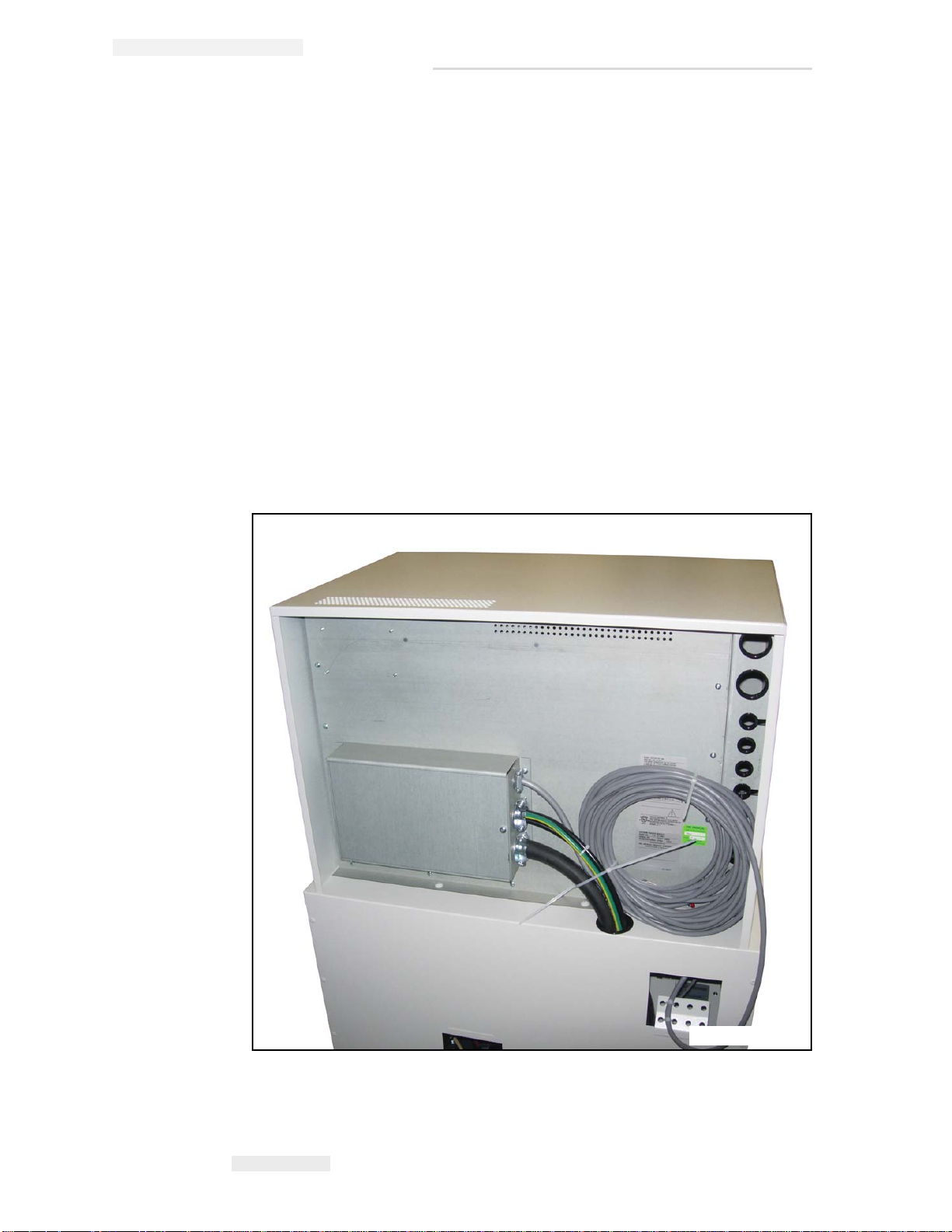
Identification Labels
The generator components have manufacturing and certification
information affixed. The manufacturing label contains:
• The full name and address of the manufacturer of the component
• The place, month, and year of manufacture
• The model number and serial number of the component
The certification label also states that the component complies with either
“21CFR, Subchapter J”, or the applicable DHHS standards under the
Radiation Control for Health and Safety Act of 1968 (or its equivalent).
A label may combine both manufacturing and certification information.
Generator Labels
The generator identification label is located on the back of the upper
cabinet as shown in Figure i-1.
Figure i-1. Generator Identification Label.
i-12 Identification Labels

Anthem Generator Installation, Operation & Service Manual
Manufacturer’s Responsibility
Although this equipment incorporates protection against X-radiation
other than the useful beam, practical design does not provide complete
protection. Equipment design does not compel the operator or assistants
to take the necessary precautions; nor does it prevent the possibility of
improper use (authorized or unauthorized persons carelessly, unwisely,
or unknowingly exposing themselves or others to direct or secondary
radiation). Allow only authorized, properly trained personnel to operate
this equipment.
Be certain that all individuals authorized to use the equipment are aware
of the danger of excessive exposure to X-radiation.
This equipment is sold with the understanding that the manufacturer, its
agents, and representatives, do not accept any responsibility for
overexposure of patients or personnel to X-radiation.
Furthermore, the manufacturer does not accept any responsibility for
overexposure of patients or personnel to X-ray radiation generated by the
equipment used in conjunction with the Anthem’s components as a result
of poor operating techniques or procedures.
No responsibility is assumed for any unit that has not been serviced and
maintained in accordance with the technical service manual, or which has
been modified or tampered with in any way.
Manufacturer’s Responsibility i-13

Anthem Generator Installation, Operation & Service Manual
Monitoring Personnel
Monitoring personnel to determine the amount of radiation to which they
have been exposed provides a valuable crosscheck to determine whether
or not safety measures are adequate. This crosscheck may reveal
inadequate or improper radiation protection practices and/or serious
radiation exposure situations.
The most effective method of determining whether the existing protective
measures are adequate is the use of instruments to measure the exposure
(in rads). This measurement should be taken at all locations where the
operator, or any portion of the operator’s body, may be inadequately
shielded during exposure. Exposure must never exceed the accepted
tolerable dose.
A frequently used, but less accurate, method of determining the amount of
exposure is placement of film at strategic locations. After a specified
period of time, develop the film to determine the amount of radiation.
Fluorescent screens (used in a darkened room) may also be used to detect
excessive radiation.
A common method of determining whether personnel have been exposed
to excessive radiation is the use of film badges. These are X-ray sensitive
film enclosed in a badge that incorporates metal filters of varying degrees
of transparency to X-ray radiation. Even though this device only measures
the radiation reaching the area of the body on which it is worn, it does
provide an indication of the amount of radiation received.
i-14 Monitoring Personnel
Anthem Generator Installation, Operation & Service Manual
Warning
Caution
Radiation Protection Survey
A radiation protection survey must be made by a qualified expert after
every change in equipment or change in operating conditions which
might significantly increase the probability of personnel receiving more
than the maximum permissible dose equivalent.
Restrictions on Use
Do not install components or accessories that were not intended
for use by the system. Failure to comply could result in damage to
the equipment or injury to personnel.
The user is responsible for ensuring that the application and use of the
Anthem does not compromise the patient contact rating of any equipment
used in the vicinity of, or in conjunction with, the system.
Observe all safety precautions recommended by the accessory
equipment manufacturer in the user documentation provided with
the equipment.
The hardware specified for use with the Anthem has been selected, tested,
and verified by Del Medical to meet the intended applications. All
specified hardware meets applicable regulatory agency requirements for
those countries where it is offered for sale with respect to its intended
applications.
Radiation Protection Survey i-15

Anthem Generator Installation, Operation & Service Manual
Hazardous Materials
The X-ray tube and collimator used with the Anthem contain lead. Refer
to the manual provided with the X-ray tube and collimator for additional
information regarding hazardous materials.
i-16 Hazardous Materials

Applicable Standards
The Anthem generator complies with the following regulatory
requirements and design standards:
• Conforms to UL 60601-1, Can/CSA C22.2 No. 601.1, IEC60601-1,
IEC60601-2-7.
Type of protection against electric shock: Class I.
No applicable parts.
Degree of protection against harmful ingress of water: Ordinary
equipment.
Mode of operation: Continuous with intermittent loading (1% duty
cycle).
Equipment not suitable for use in presence of a FLAMMABLE
ANESTHETIC MIXTURE WITH AIR OR WITH OXYGEN OR NITROUS
OXIDE.
Anthem Generator Installation, Operation & Service Manual
Applicable Standards i-17
Anthem Generator Installation, Operation & Service Manual
FP10-0031.00
1
2
3
4
Buss
6
5
Ground
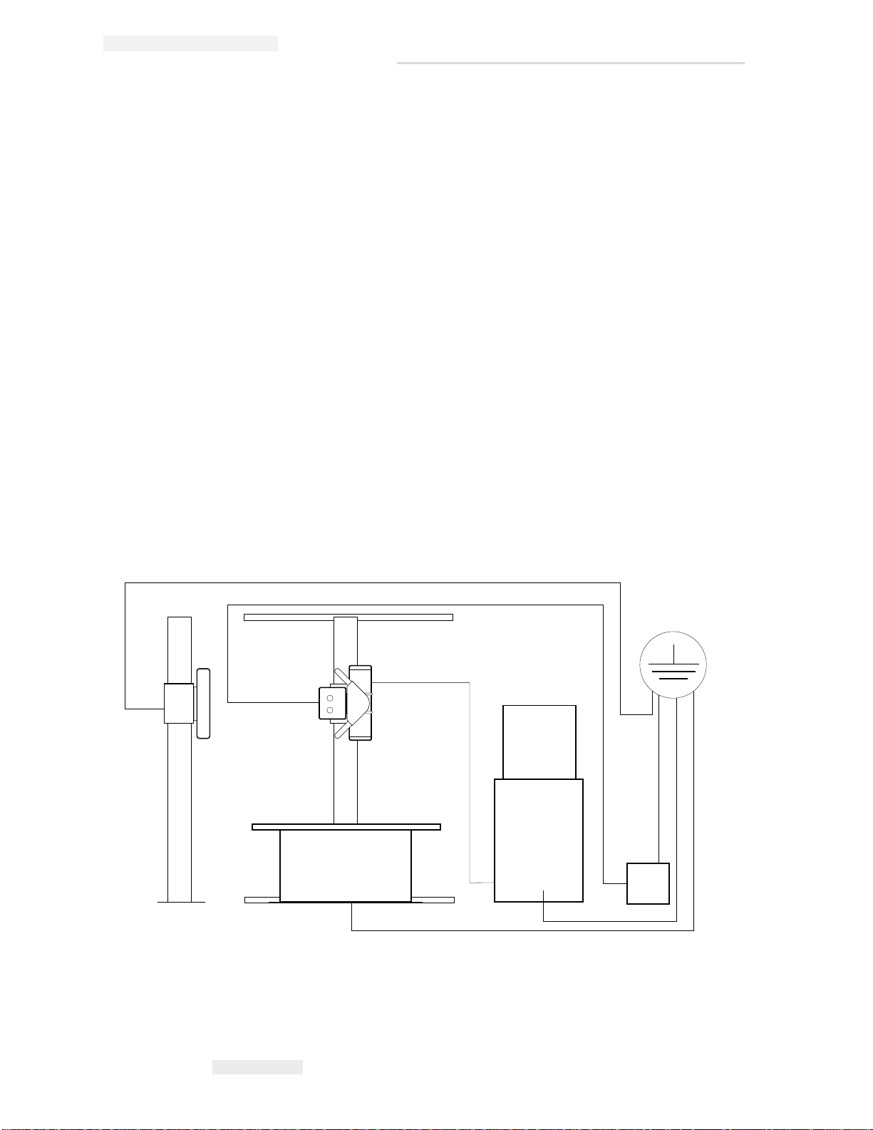
Grounding Information
This equipment must be grounded to a separate earth ground. No other
means is acceptable. Refer to the National Electrical Code for grounding of
Radiographic equipment.
The figure below shows a typical interconnected x-ray system with an xray generator.
It is comprised of:
1 Wall Stand
2 Collimator
3 X-Ray Tube
4 Table
5 X-Ray Generator
6 Collimator Power Supply
All of these components are grounded to a common bus according to
national and local electrical codes. Also, All of the components comply
with UL 60601 Standards.
Figure i-2. System Grounding.
i-18 Grounding Information

Anthem Generator Installation, Operation & Service Manual
Caution
Warning
Optical fiber components
Some of the equipment built-in into this X-ray system may use optical
fiber cables and connections for signal transmission.
Fiber optic components are very delicate. Improper handling may
cause costly interruptions in operation of the system.
To prevent eye damage, never look directly into a fiber optic cable
connector or mating adapter. Never assume laser power is turned
off or the fiber is disconnected at the other end.
Considering the fact that an optical fiber is a strand of glass about the
same diameter as a human hair, fiber optic patch cords and connectors are
remarkably durable. However, careful handling will ensure continued
high performance and long life. Do not pull or kink patch cords, as the
glass strand in the middle might become damaged or broken. Even if the
fiber is not permanently damaged, a sharp bend will cause excessive
signal loss.
Fiber optic cables work by bending the light signal as it travels. But, the
light can only tolerate so much bending. Keep patch cord bend radius no
less than an inch. Never use tie wraps as you would with electrical cables.
If there is need for routing, connecting, and/or disconnecting fiber optic
cables, follow the handling procedures below to minimize the time and
expense associated with broken component fibers.
1.0.2 How to handle fiber optic components
• Wear finger cots or gloves. Your hands may look clean, but dirt and
oils on them can damage the fiber and contaminate connectors.
• Never use the fiber pigtail to pick up or support the weight of the
device. Keep both the device and the optical connector together in
your hand(s)
• The fiber is made of a very pure, expensive glass. Treat it with the
same care that would be used when handling expensive crystal glass.
• Do not allow kinks or knots to develop in the fiber.
Optical fiber components i-19

Anthem Generator Installation, Operation & Service Manual
- Carefully work out any tangles-patience will save time and money
- Do not pull on the fiber when kinks or knots are present. Pulling will
only cause knots, kinks, and curls to tighten, increasing the risk of
breakage.
• Always use the correct tools for stripping and cleaving the fiber. It
will save time and reduce breakage caused by scratches.
• Follow all ESD precautions and approved fiber cleaning procedures.
Always read and comply with the handling instructions on the shipping
container.
i-20 Optical fiber components
 Loading...