

Page 1

Dell Latitude XT3
Owner's Manual
Regulatory Model P17G
Regulatory Type P17G001
Page 2

Notes, Cautions, and Warnings
NOTE: A NOTE indicates important information that helps you make better use of your
computer.
CAUTION: A CAUTION indicates potential damage to hardware or loss of data if
instructions are not followed.
WARNING: A WARNING indicates a potential for property damage, personal injury, or
death.
Information in this publication is subject to change without notice.
© 2011 Dell Inc. All rights reserved. Printed in the U.S.A.
Reproduction of these materials in any manner whatsoever without the written permission of Dell Inc. is
strictly forbidden.
Trademarks used in this text: Dell™, the Dell logo, Dell Precision™ , OptiPlex™ Latitude™, PowerEdge™,
PowerVault™, PowerConnect™, OpenManage™, EqualLogic™, Compellent™, KACE™, FlexAddress™ and
Vostro™ are trademarks of Dell Inc. Intel®, Pentium®, Xeon®, Core® and Celeron® are registered
trademarks of Intel Corporation in the U.S. and other countries. AMD® is a registered trademark and
AMD Opteron™, AMD Phenom™ and AMD Sempron™ are trademarks of Advanced Micro Devices, Inc.
Microsoft®, Windows®, Windows Server®, MS-DOS® and Windows Vista® are either trademarks or
registered trademarks of Microsoft Corporation in the United States and/or other countries. Red Hat
®
Red Hat
countries.
and other countries.
Xen
Enterprise Linux
Novell
®
XenServer
,
the United States and/or other countries.
®
®
®
are registered trademarks of Red Hat, Inc. in the United States and/or other
is a registered trademark and
®
Oracle
is a registered trademark of Oracle Corporation and/or its affiliates.
and
XenMotion
®
are either registered trademarks or trademarks of Citrix Systems, Inc. in
VMware
™
SUSE
is a trademark of Novell Inc. in the United States
®
Virtual SMP
,
®
vMotion
,
®
,
vCenter
®
and
registered trademarks or trademarks of VMware, Inc. in the United States or other countries.
Other trademarks and trade names may be used in this publication to refer to either the entities claiming the
marks and names or their products. Dell Inc. disclaims any proprietary interest in trademarks and trade
names other than its own.
Citrix
vSphere
®
®
and
®
are
,
2011 — 10
Rev. A00
Page 3

Contents
Notes, Cautions, and Warnings..................................................................2
1 Working on Your Computer......................................................................9
Before Working Inside Your Computer.............................................................................9
Recommended Tools.......................................................................................................11
Turning Off Your Computer..............................................................................................11
After Working Inside Your Computer..............................................................................11
2 Tablet PC Features...................................................................................13
Introduction.....................................................................................................................13
User Modes..............................................................................................................13
Tablet PC Buttons.....................................................................................................14
Scroll Buttons...........................................................................................................15
Tablet PC Interface...................................................................................................15
Tablet PC Settings.....................................................................................................25
3 Battery........................................................................................................31
Removing the Battery......................................................................................................31
Installing the Battery.......................................................................................................32
4 Subscriber Identity Module (SIM) Card...............................................33
Removing the Subscriber Identity Module (SIM) Card...................................................33
Installing the Subscriber Identity Module (SIM) Card....................................................34
5 ExpressCard..............................................................................................35
Removing the ExpressCard.............................................................................................35
Installing the ExpressCard..............................................................................................36
6 Back Panel................................................................................................37
Removing the Back Panel...............................................................................................37
Page 4

Installing the Back Panel................................................................................................38
7 Hard Drive..................................................................................................39
Removing the Hard Drive Assembly................................................................................39
Installing the Hard Drive Assembly.................................................................................41
8 Memory......................................................................................................43
Removing the Memory....................................................................................................43
Installing the Memory.....................................................................................................44
9 Bluetooth Card..........................................................................................45
Removing the Bluetooth Module.....................................................................................45
Installing the Bluetooth Module......................................................................................46
10 Wireless Local Area Network (WLAN) Card.....................................47
Removing the Wireless Local Area Network (WLAN) Card............................................47
Installing the Wireless Local Area Network (WLAN) Card.............................................48
11 Wireless Wide Area Network (WWAN) Card...................................49
Removing the Wireless Wide Area Network (WWAN) Card..........................................49
Installing the Wireless Wide Area Network (WWAN) Card...........................................50
12 Coin-Cell Battery....................................................................................51
Removing the Coin-Cell Battery......................................................................................51
Installing the Coin-Cell Battery.......................................................................................52
13 Base Cover..............................................................................................53
Removing the Base Cover...............................................................................................53
Installing the Base Cover................................................................................................54
14 Heat Sink..................................................................................................55
Removing the Heat Sink..................................................................................................55
Installing the Heat Sink...................................................................................................56
Page 5

15 Processor................................................................................................57
Removing the Processor.................................................................................................57
Installing the Processor..................................................................................................58
16 Keyboard Trim.........................................................................................59
Removing the Keyboard Trim..........................................................................................59
Installing the Keyboard Trim...........................................................................................59
17 Keyboard..................................................................................................61
Removing the Keyboard..................................................................................................61
Installing the Keyboard...................................................................................................63
18 Palm Rest.................................................................................................65
Removing the Palm Rest..................................................................................................65
Installing the Palm Rest...................................................................................................67
19 Display Closure Sensor.........................................................................69
Removing the Display Closure Sensor............................................................................69
Installing the Display Closure Sensor.............................................................................70
20 ExpressCard Reader..............................................................................71
Removing the ExpressCard Reader.................................................................................71
Installing the ExpressCard Reader..................................................................................72
21 Smart Card Reader.................................................................................73
Removing the Smart Card Reader...................................................................................73
Installing the Smart Card Reader....................................................................................74
22 Wireless Switch.....................................................................................75
Removing the WLAN Switch Board................................................................................75
Installing the WLAN Switch Board.................................................................................76
23 Speaker....................................................................................................77
Removing the Speakers..................................................................................................77
Page 6

Installing the Speakers....................................................................................................79
24 Bluetooth Cable......................................................................................81
Removing the Bluetooth Cable........................................................................................81
Installing the Bluetooth Cable.........................................................................................81
25 Modem Connector.................................................................................83
Removing the Modem Connector....................................................................................83
Installing the Modem Connector.....................................................................................85
30 Display Bezel...........................................................................................87
Removing the Display Bezel............................................................................................87
Installing the Display Bezel.............................................................................................87
27 System Board..........................................................................................89
Removing the System Board...........................................................................................89
Installing the System Board............................................................................................91
28 Power Connector...................................................................................93
Removing the Power Connector.....................................................................................93
Installing the Power Connector.......................................................................................94
30 Display Bezel...........................................................................................97
Removing the Display Bezel............................................................................................97
Installing the Display Bezel.............................................................................................97
30 Display Bezel...........................................................................................99
Removing the Display Panel............................................................................................99
Installing the Display Panel...........................................................................................101
31 Camera...................................................................................................103
Removing the Camera...................................................................................................103
Installing the Camera....................................................................................................104
Page 7

32 Display Function Board and Cable....................................................105
Removing the Display Function Board..........................................................................105
Installing the Display Function Board...........................................................................107
33 Display Power Board...........................................................................109
Removing the Display Power Board..............................................................................109
Installing the Display Power Board...............................................................................111
34 Fingerprint Board.................................................................................113
Removing the Display Fingerprint Board and Cable.....................................................113
Installing the Display Fingerprint Board and Cable.......................................................115
35 Display Assembly.................................................................................117
Installing the Display Assembly....................................................................................117
Installing the Display Assembly....................................................................................117
36 Display Hinges......................................................................................119
Removing the Display Hinge Assembly.........................................................................119
Installing the Display Hinge Assembly..........................................................................121
37 Low-Voltage Differential Signaling (LVDS) Camera Cable............123
Removing the LVDS Camera Cable...............................................................................123
Installing the LVDS Cable..............................................................................................123
38 Specifications.......................................................................................125
Specifications................................................................................................................125
39 System Setup........................................................................................131
Overview .......................................................................................................................131
Entering System Setup..................................................................................................131
System Setup Options...................................................................................................131
40 Contacting Dell.....................................................................................141
Contacting Dell..............................................................................................................141
Page 8

8
Page 9

1
Working on Your Computer
Before Working Inside Your Computer
Use the following safety guidelines to help protect your computer from potential damage
and to help to ensure your personal safety. Unless otherwise noted, each procedure
included in this document assumes that the following conditions exist:
• You have performed the steps in Working on Your Computer.
• You have read the safety information that shipped with your computer.
• A component can be replaced or--if purchased separately--installed by performing
the removal procedure in reverse order.
WARNING: Before working inside your computer, read the safety information that
shipped with your computer. For additional safety best practices information, see
the Regulatory Compliance Homepage at www.dell.com/regulatory_compliance.
CAUTION: Many repairs may only be done by a certified service technician. You
should only perform troubleshooting and simple repairs as authorized in your
product documentation, or as directed by the online or telephone service and
support team. Damage due to servicing that is not authorized by Dell is not covered
by your warranty. Read and follow the safety instructions that came with the
product.
CAUTION: To avoid electrostatic discharge, ground yourself by using a wrist
grounding strap or by periodically touching an unpainted metal surface, such as a
connector on the back of the computer.
CAUTION: Handle components and cards with care. Do not touch the components
or contacts on a card. Hold a card by its edges or by its metal mounting bracket.
Hold a component such as a processor by its edges, not by its pins.
9
Page 10

CAUTION: When you disconnect a cable, pull on its connector or on its pull-tab, not
on the cable itself. Some cables have connectors with locking tabs; if you are
disconnecting this type of cable, press in on the locking tabs before you disconnect
the cable. As you pull connectors apart, keep them evenly aligned to avoid bending
any connector pins. Also, before you connect a cable, ensure that both connectors
are correctly oriented and aligned.
NOTE: The color of your computer and certain components may appear differently
than shown in this document.
To avoid damaging your computer, perform the following steps before you begin working
inside the computer.
1. Ensure that your work surface is flat and clean to prevent the computer cover from
being scratched.
2. Turn off your computer (see
3. If the computer is connected to a docking device (docked) such as the optional
Media Base or Battery Slice, undock it.
CAUTION: To disconnect a network cable, first unplug the cable from your
computer and then unplug the cable from the network device.
4. Disconnect all network cables from the computer.
5. Disconnect your computer and all attached devices from their electrical outlets.
6. Close the display and turn the computer upside-down on a flat work surface.
NOTE: To avoid damaging the system board, you must remove the main battery
before you service the computer.
7. Remove the main battery.
8. Turn the computer top-side up.
9. Open the display.
10. Press the power button to ground the system board.
CAUTION: To guard against electrical shock, always unplug your computer from the
electrical outlet before opening the display.
CAUTION: Before touching anything inside your computer, ground yourself by
touching an unpainted metal surface, such as the metal at the back of the
computer. While you work, periodically touch an unpainted metal surface to
dissipate static electricity, which could harm internal components.
Turning Off Your Computer
).
11. Remove any installed ExpressCards or Smart Cards from the appropriate slots.
10
Page 11
Recommended Tools
The procedures in this document may require the following tools:
• Small flat-blade screwdriver
• #0 Phillips screwdriver
• #1 Phillips screwdriver
• Small plastic scribe
• Flash BIOS update program CD
Turning Off Your Computer
CAUTION: To avoid losing data, save and close all open files and exit all open
programs before you turn off your computer.
1. Shut down the operating system:
• In Windows Vista :
Click Start , then click the arrow in the lower-right corner of the Start menu
as shown below, and then click Shut Down.
• In Windows XP:
Click Start → Turn Off Computer → Turn Off . The computer turns off after the
operating system shutdown process is complete.
2. Ensure that the computer and all attached devices are turned off. If your computer
and attached devices did not automatically turn off when you shut down your
operating system, press and hold the power button for about 4 seconds to turn them
off.
After Working Inside Your Computer
After you complete any replacement procedure, ensure you connect any external
devices, cards, and cables before turning on your computer.
CAUTION: To avoid damage to the computer, use only the battery designed for this
particular Dell computer. Do not use batteries designed for other Dell computers.
11
Page 12

1. Connect any external devices, such as a port replicator, battery slice, or media
base, and replace any cards, such as an ExpressCard.
2. Connect any telephone or network cables to your computer.
CAUTION: To connect a network cable, first plug the cable into the network device
and then plug it into the computer.
3. Replace the battery.
4. Connect your computer and all attached devices to their electrical outlets.
5. Turn on your computer.
12
Page 13

Tablet PC Features
Introduction
Your computer is a Tablet PC that has the following features:
•
User Modes
•
Tablet Buttons
•
Tablet PC Interface
•
Tablet Settings
User Modes
You can use your Tablet PC in two different modes:
• Notebook mode
• Tablet mode
Using Your Tablet PC in the Tablet Mode
You can convert your Tablet PC from notebook mode to tablet mode with a 180–degree
clockwise and anti-clockwise twist of the display's rotating hinge.
2
NOTE: Do not force the hinge beyond the 180–degree point, it will damage your
tablet PC.
1. Open the display of the Tablet PC.
2. Brace the base with one hand on the palm rest, grasp the top of the display with the
other hand, and, following the directional arrow inscribed on the hinge cover, turn
the rotating hinge clockwise 180–degree until you feel the display engage securely.
13
Page 14
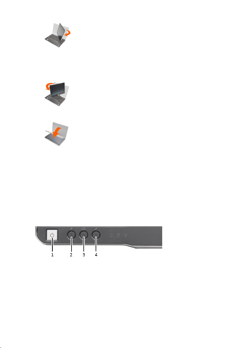
3. Brace the base with one hand on the palm rest, grasp the top of the display with the
other hand, and, following the directional arrow inscribed on the hinge cover, turn
the rotating hinge counter clockwise 180–degree until you feel the display engage
securely.
4. Lay the display assembly on the base with the display facing upwards.
Portrait orientation refers to tablet mode usage in which the user holds the system with
primary focus on the vertical space. Landscape orientation refers to tablet mode usage
in which the user holds the system with primary focus on the horizontal space. By
definition, notebook mode is always in landscape orientation.
Tablet PC Buttons
Your Tablet PC has three tablet buttons located beside the power button. In order for
these buttons to function properly, Dell Control Point System Manager must be installed.
1. Power button — Used to power the computer On or Off.
2. Windows security button — If you use your Tablet-PC in tablet mode, press this
button to access the Windows Task Manager dialog box or a login screen, the
same way you use the <Ctrl><Alt><Del>key sequence in the notebook mode.
3. Screen rotate button — While the Tablet-PC is in tablet mode, use the screen
rotate button to change the display orientation from portrait to landscape mode.
Each time you press and release the screen rotate button, the screen image rotates
clockwise 90 degrees.
14
Page 15
4. Dell control point button — Press this button to view and configure options for the
Tablet PC and the pen through Dell Control Point System Manager.
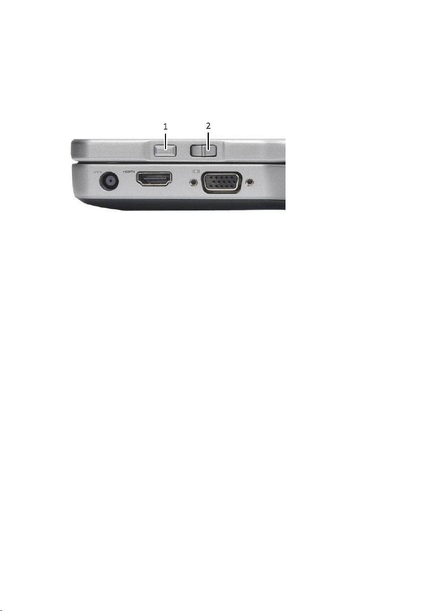
Scroll Buttons
Your Tablet-PC has two scroll buttons.
Figure 1. Scroll Buttons
1. Scroll control
2. Back button
Using the Scroll Control
• To scroll through a list of items or a set of pages one at a time, shift the scroll control
up or down and release. The control automatically returns to the center/neutral
position when released.
• To rapidly scroll through a list of items or a set of pages, shift the control up or down
and hold it, releasing it when you wish to stop scrolling.
• To select objects, press and release the scroll control when it is in the center/neutral
position.
• To launch context sensitive menus, press and hold the scroll control until a complete
circle is drawn on the display then release. This is equivalent to clicking the right
mouse button on a notebook computer.
Using the Back Button
• To move backward, press and release the back button.
• To close the active window, press and hold the back button.
• To customize the back button behavior, use the Tablet and Pen Settings in Windows
Vista.
Tablet PC Interface
Your Tablet PC is offered with the following operating systems:
15
Page 16

• Windows 7
• Windows Vista
• Windows XP
There are several differences in the Tablet PC interfaces between the three operating
systems. The primary difference are listed below.
Feature Description Windows 7/
Touch Ability to use finger as an input device. Yes Yes
Windows
Journal
Snipping
Tool
Flicks Gesture activated shortcuts for common
Check
Boxes
Cursor
Feedback
Tablet
Input Panel
Input
devicesensitive
tools
Tablet
Cursor
Native note-taking application which takes
input directly from pen or touch.
Tool used to capture portions of visual data
(documents, pictures, etc.) via pen or touch.
tasks.
Visual identifier in folders for selecting files. Yes No
Visual indicator for tap location. Yes No
Tool used to input data via pen or touch that
takes the place of a keyboard.
Tablet Input Panel and icon change size
according to pen or touch being used.
Special Tablet cursor used for Tablet-PC
functions as opposed to a standard mouse
pointer.
Windows
Vista
Yes Yes
Yes Yes
Yes No
Yes Yes
Yes No
Yes No
Windows
XP
Touch
Widget
Cursor
Feedback
16
Separate tool that appears in Touch Mode
used for right-clicking purposes.
Ability to see if the target has been hit by
using visual feedback for success.
Yes No
Yes No
Page 17

Using Your Tablet PC in Windows 7
Your Tablet PC uses several input devices. The standard keyboard touch pad are
present, plus you can opt for the electrostatic pen or just use your finger as an input
device.
Using Pen as a Mouse
You can use the pen the same way you use a mouse or touch pad with a notebook
computer. Holding the pen near the display makes a small cursor appear. Moving the
pen moves the cursor. The table below describes how to use the pen.
Function Action
Single-click on a mouse Gently tap the pen tip on the screen of your Tablet
PC.
Double-click on a mouse Gently tap the pen tip twice in quick succession
on the screen of your Tablet PC.
Right-click on a mouse Touch the pen on the screen and hold it in place
momentarily until Windows draws a complete
circle around the cursor.
Working With Files
You can open, delete, or move many files or folders at one time by selecting multiple
items from a list. Using a tablet pen, hover over one item at a time and select the check
box that appears to the left of each item.
To activate the check boxes:
1. Go to Control Panel.
2. Go to Folder Options.
3. Click View .
4. Under Advanced settings, select the Use check boxes to select items check box,
and then click OK.
Using Pen as a Pen
The handwriting recognition software makes it easy to enter text into your applications
with the pen. Some applications, such as Windows Journal, allow you to write with the
pen directly into the application window.
The primary features of using Pen are:
• Tablet PC Input Panel
• Pen Flicks
17
Page 18
To enter the text, you can use the handwriting recognition software or the touch
keyboard to enter text:
Icon Function
Handwriting recognition — The writing pad and character pad convert
handwriting into typed text. You can write continuously on the writing
pad, like writing on a piece of lined paper. Use the character pad to
enter one character at a time. The character pad converts your
handwriting to typed text, one letter, number or symbol at a time, but
doesn't take the context of the full word into account and doesn't take
advantage of the handwriting dictionary. To switch to the character pad
in Input Panel, tap Tools, and then Write character by character
Touch keyboard — The touch keyboard is like a standard keyboard, but
you enter text by tapping the keys with your tablet pen or finger.
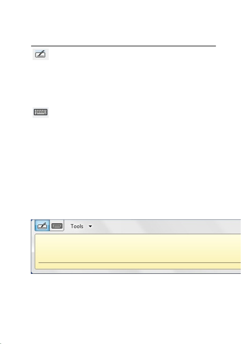
Using Tablet PC Input Panel
Tablet PC input panel allows you enter text into your applications, when an application
does not directly support pen input.
You can access the Tablet PC input panel performing either of the following actions:
• Tap your pen in an editable area in the application. The Tablet PC Input Panel icon
appears. Tapping the Tablet PC icon makes Input Panel slide out from the edge of the
display.
• Tap the Input Panel tab, which is docked at the edge of the screen when the Input
Panel is hidden.
• You can move the Input Panel tab by dragging it up or down along the edge of the
screen. Then, when you tap it, the Input Panel opens at the same horizontal location
on the screen that the tab appears.
Figure 2. Table PC Input Panel
The writing pad and character pad have a number pad, a symbol pad, and web quick
keys to help you quickly and accurately enter these types of text. These quick keys are
hidden when you start to write, but appear after you insert or delete your writing.
18
Page 19

NOTE: By default, Input Panel automatically switches to the touch keyboard when
you place the insertion point in a box for entering a password.
Entering Text
You can use handwriting recognition or the touch keyboard to enter text. The writing pad
and character pad have a number pad, a symbol pad, and web quick keys to help you
quickly and accurately enter these types of text. These quick keys are hidden when you
start to write, but appear after you insert or delete your writing. The following table
displays the Input Panel icons and their functions.
Icon Name Function
Hand
writing
recog
nition
Touch
keybo
ard
NOTE: By default, the Input Panel automatically switches to the touch keyboard
when you place the insertion point in a box for entering a password.
The writing pad and character pad convert handwriting into typed text.
You can write continuously on the writing pad, like writing on a piece
of lined paper. Use the character pad to enter one character at a time.
The character pad converts your handwriting to typed text, one letter,
number or symbol at a time, but doesn't take the context of the full
word into account and doesn't take advantage of the handwriting
dictionary. To switch to the character pad in Input Panel, tap Tools,
and then write character by character
The touch keyboard is like a standard keyboard, but you enter text by
tapping the keys with your tablet pen or finger.
Pen Flicks
Pen flicks allow you to use the pen to perform actions that normally require a keyboard,
such as pressing <Page Up>or using the directional arrow keys. Pen flicks are quick,
directional gestures. When a pen flick is recognized, the Tablet PC performs the action
assigned.
19
Page 20
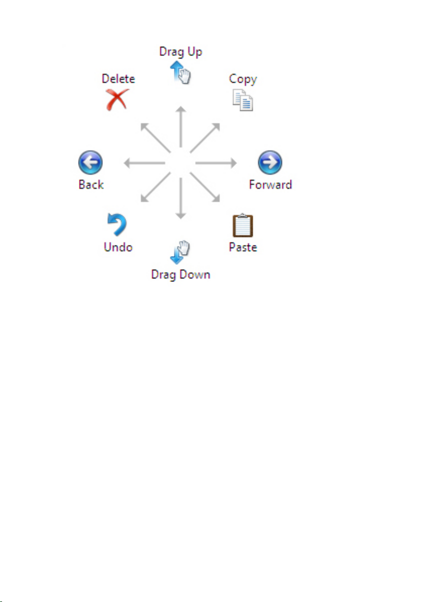
Figure 3. Default Pen Flicks
You can customize the pen flicks by performing the following action:
• Start> Control Panel> Pen and Touch and clicking on the Flicks tab.
20
Page 21
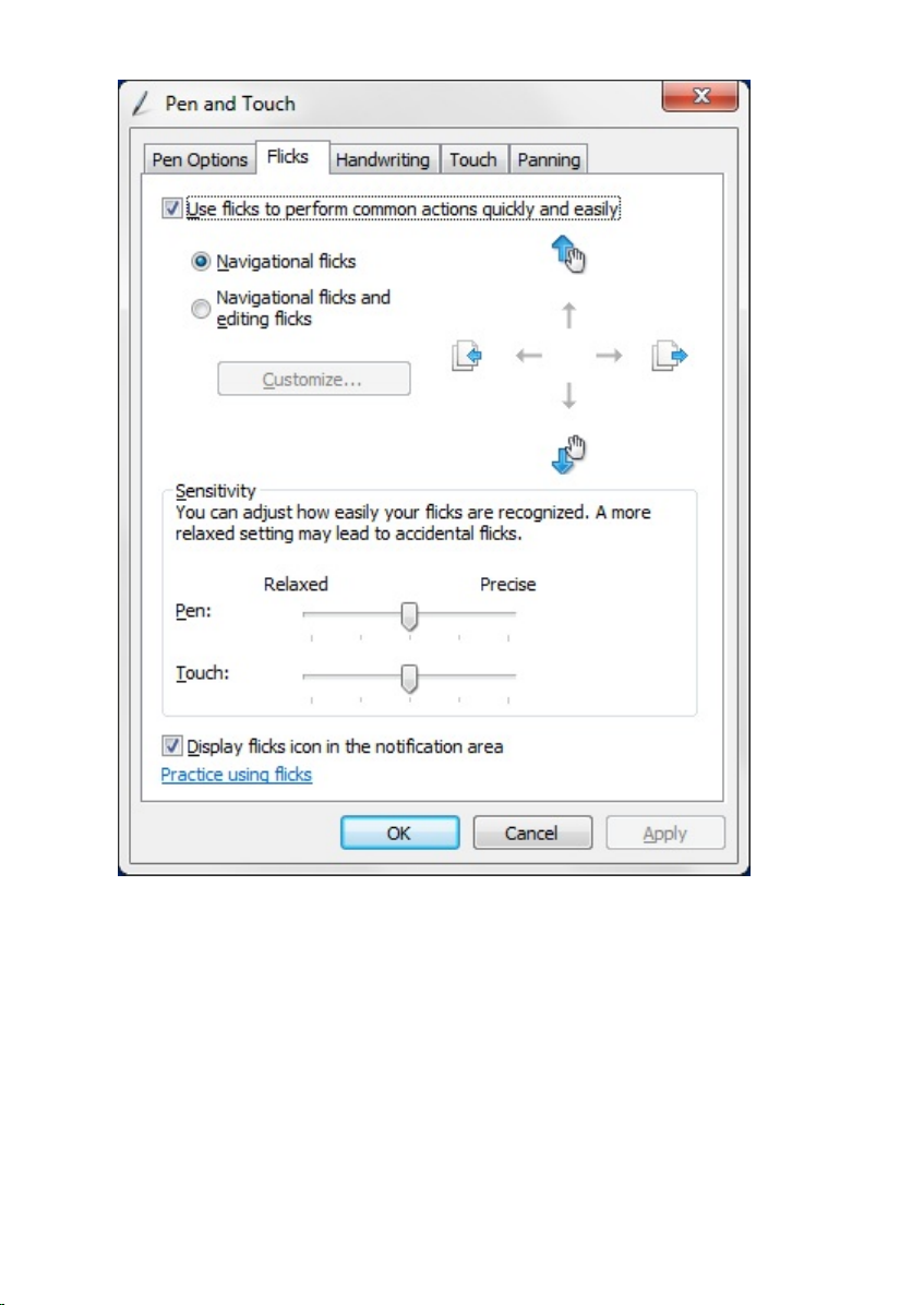
Figure 4. Pen and Touch — Pen Flicks
Touch Usage
The key advantage of your Tablet PC is the ability to easily switch from pen input to touch
input. When you use Touch Mode, a translucent image of a computer mouse, called the
touch pointer, floats beneath your finger. The touch pointer has left and right mouse
buttons that you can tap with your finger. You use the area beneath the buttons to drag
the touch pointer.
To enable the touch pointer:
• Go to Start> Control Panel> Pen and Touch and click the Touch tab.
21
Page 22
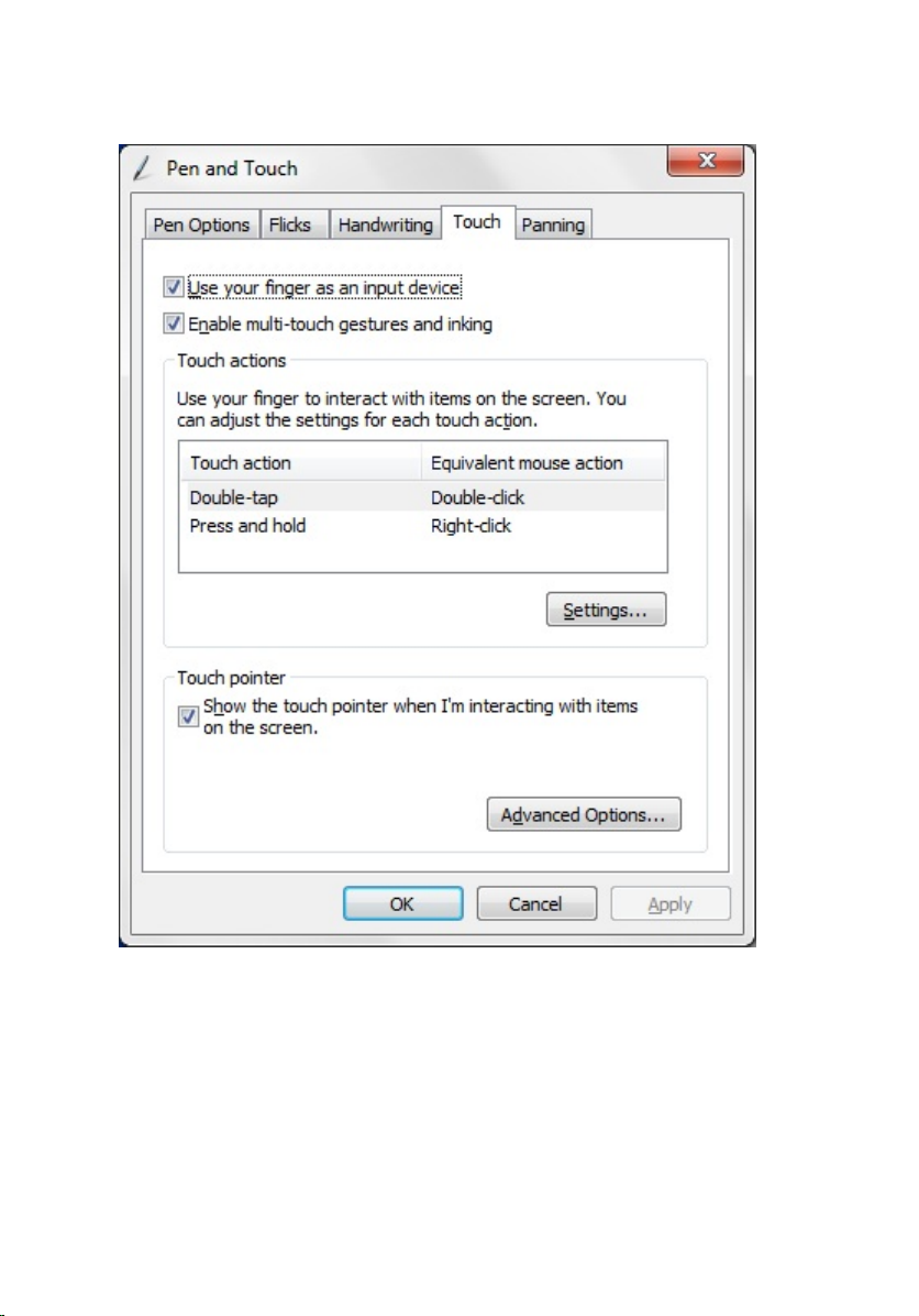
• On the Touch Pointer section, select the Show the touch pointer when I'm interacting
with items on the screen option.
Figure 5. Pen and Touch — Touch Usage
Using Your Tablet PC in Windows XP
You can use different input devices on your Tablet PC. The standard keyboard touch pad
are present, plus you can opt for the electrostatic pen or just use your finger as an input
device
22
Page 23

Using Pen as a Mouse
You can use the pen the same way you use a mouse or touch pad with a notebook
computer. Holding the pen near the display makes a small cursor appear. Moving the
pen moves the cursor. Tapping on the screen once is the same as clicking with a mouse.
A double-tap constitutes a double-click. Right-clicking with the pen is accomplished by
holding the pen tip down on the screen until a red circle surrounds the pointer as
illustrated below. Lifting the pen from the specific location opens up the corresponding
submenu.
Figure 6. Pointer Indicator
Using Pen as a Pen
The native handwriting recognition software makes it easy to enter text into your
applications with the pen. Some applications, such as Windows Journal, allow you to
write with the pen directly into the application window.
Tablet PC Input Panel
You can use the Tablet PC input panel to enter text into your application, when the
application does not directly support pen input.
You can access the Tablet PC input panel by tapping your pen in an editable area in the
application. The Tablet PC Input Panel icon appears.
You can use the writing pad, the character pad, or the on-screen keyboard to enter text.
The writing pad and the character pad convert your handwriting into typed text. The onscreen keyboard works just like a standard keyboard except that you enter text by
tapping keys with your tablet pen. The following table describes the different choices for
using the Input Panel.
Touch Usage
The key advantage of your Tablet-PC is the ability to easily switch from pen input to
touch input. Similar to how the pen works, tapping with your finger on the screen once is
the same as clicking with a mouse. A double-tap constitutes a double-click. Rightclicking in Touch Mode is accomplished by holding your finger tip down on the screen
until a red circle surrounds the pointer. This can be difficult to see as often times user's
fingers cover the pointer. Lifting your finger from this point opens up the corresponding
submenu.
Tablet and Pen Settings
You can access the Table and Pen Settings from the Control Panel. You can also access
it from the Dell Control Point Manager.
23
Page 24
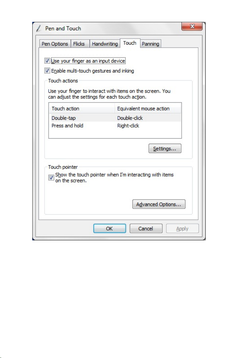
Figure 7. Pen and Touch Window
The following are the different sections that is available in the Pen and Touch window.
They are:
• Settings — Allows you to define the right/left handedness, location of the menu and
calibration settings.
• Display — Allows you to define the screen orientation and set the screen brightness.
• Tablet Buttons — Allows you to define the button settings.
• Pen Options — Allows you to define the different actions of the pen and the pen
buttons for different functions.
.
24
Page 25
Tablet PC Settings
The N-trig Tablet Settings applet is used to adjust several settings for the digitizer. the Ntrig applet icon appears in the system tray. Hovering over the icon with your pointer
displays the firmware version number. Right-clicking the icon brings up the sub menu of
Properties and Aboutoptions. There are four tabs on the N-trig DuoSense Digitizer
Settings window:
• Digitizer Options
• Pen
• Interactive Options
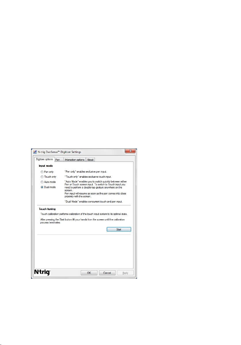
Digitizer Options Tab
The Digitizer Options tab is used for the following
• Input mode selection
• Touch tuning
Figure 8. N-trig DuoSense Digitizer Settings — Digitizer options
Input Mode
The N-trig applet has four operating modes:
25
Page 26

• Pen Only— In this mode, the stylus is the only device that can be used as the input
device with the N-trig digitizer. To change from Pen only mode to any other mode:
a. Click or tap on the N-trig applet icon in the system tray.
b. On the applet window, select the desired mode and click OK
• Touch Only — In Touch Only mode, a single finger is the only input device that can
be used with the N-trig digitizer. Using the stylus is not possible.
NOTE: Only a single hand contact is allowed with the digitizer for proper execution.
. To change from Touch only mode:
a. Click or tap on the N-trig applet icon in the system tray.
b. On the applet window, select the desired mode and click OK
• Auto Mode— The N-trig digitizer is capable of detecting a stylus as well as finger
touch. The purpose of Auto mode is to allow the user intuitive toggling between the
Pen only and Touch only modes. The default input device for Auto mode is the stylus
as long as it is in range of the tablet screen (hovering in proximity or in contact). A
basic principle in Auto mode is that stylus detection in the digitizer proximity would
turn the digitizer into Pen only mode as an overriding priority. A double-tap finger
gesture on the screen (similar in style to a mouse double-click) will switch the
digitizer from Pen only mode to Touch only mode. The system will remain in Touch
Only mode as long as the stylus is out of range. Once the stylus is detected in range
the system will automatically switch to Pen only mode.
• Dual Mode (Windows Vista and 7 Only) — Dual mode is a unique operational mode
that is functional only while using the Windows Vista and Windows 7 operating
system. In this mode, the Operating system switches automatically between the
available pointing device according to its internal priority and attributes.
Touch Tuning
Touch calibration performs calibration of the touch input system to its optimal state. If
the tablet's finger detection is not working properly, you may have to re-calibrate the
touch feature. To re-calibrate the touch feature:
1. Click the Start button and then follow the on-screen prompts.
.
NOTE: Do not touch the screen when the touch reset is in progress.
Pen Tab
The Pen tab allows you to:
• define the pen supported features
• view the pen battery status
26
Page 27
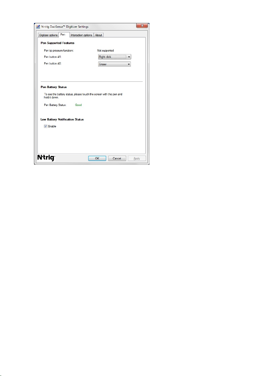
Figure 9. N-Trig DuoSense Digitizer Settings — Pen
Pen Features and Pen Battery Status
You can configure the pen buttons. There are two buttons on the pen and they are
referred as:
• Pen button #1 — This button is defined as the lowermost button on the pen shaft. By
default, this button set to right-click functionality.
• Pen button #2 — This button is located directly above the primary button. By default,
this button is set to eraser functionality.
You can change button functions to perform different functions. The options available
are:
• Disabled
• Right-click
• Eraser
In the Pen tab you can view status of the battery inserted in the pen. To see the battery
status, simply touch the screen with the pen and hold it down
Interaction Options Tab
In the Interaction Options tab, you can control the sound effects when operating the
system in various modes.
27
Page 28
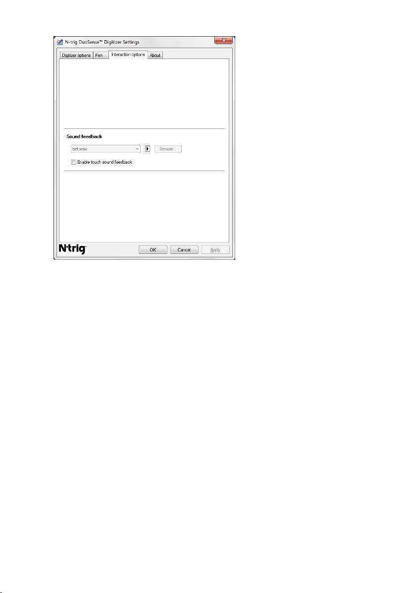
Figure 10. N-trig Duo Sense Digitizer Settings — Interaction options
You can select the .WAV file that need to be played when the finger touches the screen.
Click the Play button icon to test the sound.
Troubleshooting for N-Trig Digitizer
Installation Issues
• Error message during installation — Hardware is not adequate for running this
software
• Check if the bundle you are trying to run is for the appropriate operating system
(Windows 7 or Windows Vista or Windows XP).
• Check if the bundle you are trying to run is of the correct bit (32 bit or 64 bit).
• Installing Windows Vista/Windows XP bundle over Windows 7 firmware.
• If you have downgraded the operating system from Windows 7 to Windows
Vista/Windows XP without uninstalling the N-Trig bundle, the firmware on the
digitizer will remain for Windows 7. To revert the firmware to the default, you
have to rollback the application
• Installing Windows 7 bundle over Windows Vista/Windows XP
• If you have upgraded the operating system to Windows 7 from Windows Vista/
Windows XP, without uninstalling the N-Trig bundle, the firmware will remain for
Windows Vista/Windows XP. The Windows 7 bundles already contains the
28
Page 29
firmware rollback application. It will run the rollback tool and then continue to
install the Window 7 bundle installation.
Performance Issues
• User has no multi touch functionality
a. Check if the N-trig bundle is installed.
b. Open Control Panel and the N-trig DuoSense Digitizer Settings icon must be
displayed. If the bundle is not installed. Please install the right bundle for the
operating system installed on the computer.
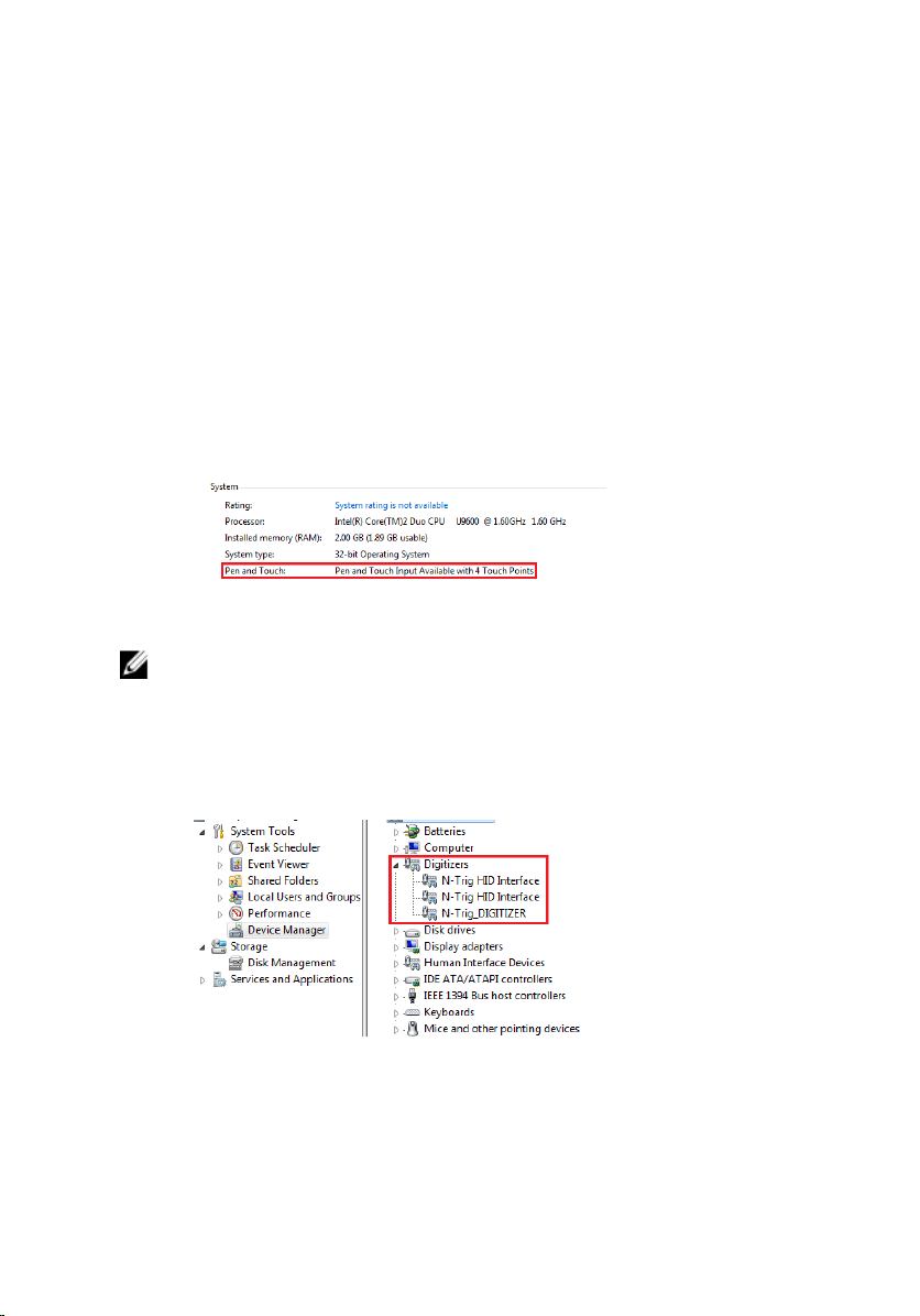
c. Check the system information to see how many touch points are detected.
1. Click on Start.
2. Right click on Computer and select Properties from the menu.
3. Number of touch points should be written in the information window .
Figure 11. System Information — Touch Points for Pen and Touch Input
NOTE: In Windows Vista and Windows XP bundles there are no 4 points multi touch
after bundle installation. The Vista/XP bundles support single touch and gestures
(two fingers).
• Bundle is installed but touch functionality is missing
a. Open the Device Manager and check that the Digitizer is recognized by the
computer.
Figure 12. Device Manager — Digitizers
b. If the device is recognized, try to uninstall the N-trig bundle and reinstall.
c. If the device is not recognized, check if you see it under Unknown Devices and
update the driver for the unknown device
29
Page 30

d. n Windows 7, after successfully installing the N-trig bundle you have to check if
the Tablet PC Components check box (in Windows Features) is selected.
1. Go to Control Panel > Programs and Features.
2. In the Programs and Features window, click the Turn Windows Features
On/Off link, located in the left sidebar
3. Check if the Tablet PC Components check box is selected.
30
Page 31

Battery
Removing the Battery
3
1. Follow the procedures in
2. Slide the release latch to unlock the battery.
3. Remove the battery from the computer.
Before Working On Your Computer.
31
Page 32

Installing the Battery
1. Slide the battery back into the computer.
The release latch automatically click into the lock position.
2. Follow the procedures in
After Working Inside Your Computer.
32
Page 33

Subscriber Identity Module (SIM) Card
Removing the Subscriber Identity Module (SIM) Card
4
1. Follow the procedures in
2. Remove the
3. Press and release the SIM card located on the battery wall.
4. Slide the SIM card from the computer.
battery
Before Working On Your Computer.
.
33
Page 34

Installing the Subscriber Identity Module (SIM) Card
1. Insert the SIM card into the slot.
2. Replace the
3. Follow the procedures in
battery.
After Working Inside Your Computer.
34
Page 35

ExpressCard
Removing the ExpressCard
5
1. Follow the procedures in
2. Remove the
3. Press in on the ExpressCard.
4. Slide the ExpressCard out of the computer.
battery
Before Working On Your Computer.
.
35
Page 36

Installing the ExpressCard
1. Insert the ExpressCard into the slot until it clicks into place.
2. Follow the procedures in
After Working Inside Your Computer.
36
Page 37

Back Panel
Removing the Back Panel
6
1. Follow the procedures in
2. Remove the
3. Remove the screws that secure the back panel.
4. Slide the back panel toward the back of the computer and lift it away from the
computer.
battery
Before Working On Your Computer.
.
37
Page 38

Installing the Back Panel
1. Attach the back panel to the back of the computer.
2. Tighten the screws to secure the back panel.
3. Replace the
4. Follow the procedures in
battery.
After Working Inside Your Computer.
38
Page 39

Hard Drive
Removing the Hard Drive Assembly
7
1. Follow the procedures in
2. Remove the
3. Remove the
4. Remove the screws that secure the hard drive to the computer.
5. Pull the hard drive out of the computer.
battery
back panel
Before Working On Your Computer.
.
.
39
Page 40

6. Remove the screw from the hard-drive bracket.
7. Remove the hard-drive bracket and slide the rubber from the hard drive.
40
Page 41

Installing the Hard Drive Assembly
1. Attach the hard-drive bracket and the rubber to the hard drive.
2. Tighten the screw to secure the hard-drive bracket and the rubber.
3. Insert the hard drive into the compartment.
4. Tighten the screws to secure the hard drive to the computer.
5. Replace the
6. Replace the
7. Follow the procedures in
back panel.
battery
.
After Working Inside Your Computer.
41
Page 42

42
Page 43

Memory
Removing the Memory
8
1. Follow the procedures in
2. Remove the
3. Remove the
4. Pry the retention clips away from the memory module.
5. Remove the memory module from the computer.
battery
back panel
Before Working On Your Computer.
.
.
43
Page 44

Installing the Memory
1. Insert the memory module into the slot.
2. Press down the memory until the securing clips secure the memory.
3. Replace the
4. Replace the
5. Follow the procedures in
back panel.
battery
.
After Working Inside Your Computer.
44
Page 45

Bluetooth Card
Removing the Bluetooth Module
9
1. Follow the procedures in
2. Remove the
3. Remove the screw that secures the bluetooth module.
4. Disconnect the bluetooth cable from the bluetooth module.
battery
Before Working On Your Computer.
.
45
Page 46

5. Remove the bluetooth module.
Installing the Bluetooth Module
1. Place the bluetooth module on the slot in the battery compartment.
2. Connect the bluetooth cable to the bluetooth module.
3. Tighten the screw to secure the bluetooth to the computer.
4. Replace the
5. Follow the procedures in
battery
.
After Working Inside Your Computer.
46
Page 47

Wireless Local Area Network (WLAN) Card
Removing the Wireless Local Area Network (WLAN) Card
10
1. Follow the procedures in
2. Remove the
3. Remove the
4. Disconnect the WLAN antenna cables from the card.
5. Remove the screw that secures the WLAN card to the system board.
battery
back panel
Before Working On Your Computer.
.
.
47
Page 48

6. Remove the WLAN card from the computer.
Installing the Wireless Local Area Network (WLAN) Card
1. Insert the WLAN card into the slot.
2. Tighten the screws to secure the WLAN card to the system board.
3. Connect the antenna cables to the WLAN card.
4. Replace the
5. Replace the
6. Follow the procedures in
48
back panel.
battery
.
After Working Inside Your Computer.
Page 49

Wireless Wide Area Network (WWAN) Card
Removing the Wireless Wide Area Network (WWAN) Card
11
1. Follow the procedures in
2. Remove the
3. Remove the
4. Disconnect the WWAN antenna cables from the card.
5. Remove the screw that secures the WWAN card to the system board.
battery
back panel
Before Working On Your Computer.
.
.
49
Page 50

6. Remove the WWAN card from the computer.
Installing the Wireless Wide Area Network (WWAN) Card
1. Insert the WWAN card into the slot.
2. Tighten the screws to secure the WWAN card to the system board.
3. Connect the antenna cables to the WWAN card.
4. Replace the
5. Replace the
6. Follow the procedures in
50
back panel.
battery
.
After Working Inside Your Computer.
Page 51

Coin-Cell Battery
Removing the Coin-Cell Battery
12
1. Follow the procedures in
2. Remove the
3. Remove the
4. Remove the
5. Disconnect the coin-cell battery cable from the system board.
6. Remove the coin-cell battery.
battery
back panel
WWAN card
Before Working On Your Computer.
.
.
.
51
Page 52

Installing the Coin-Cell Battery
1. Place the coin-cell battery into the slot.
2. Connect the coin-cell battery cable to the system board.
3. Replace the
4. Replace the
5. Replace the
6. Follow the procedures in
WWAN card
back panel.
battery
.
.
After Working Inside Your Computer.
52
Page 53

Base Cover
Removing the Base Cover
13
1. Follow the procedures in
2. Remove the
3. Remove the
4. Remove the
5. Remove the screws that secure the base cover.
6. Disengage the base cover from the edges and remove it from the computer
battery
back panel
hard drive assembly
Before Working On Your Computer.
.
.
.
53
Page 54

Installing the Base Cover
1. Attach the base cover until the edges snap into place.
2. Tighten the screws to secure the base cover.
3. Replace the
4. Replace the
5. Replace the
6. Follow the procedures in
hard drive assembly
back panel.
battery
.
After Working Inside Your Computer.
.
54
Page 55

Heat Sink
Removing the Heat Sink
14
1. Follow the procedures in
2. Remove the
3. Remove the
4. Remove the
5. Remove the
6. Disconnect the fan cable from the system board
7. Loosen the captive screws on the heat sink and remove the screws on the fan.
battery
back panel
hard drive assembly
base cover
Before Working On Your Computer.
.
.
.
.
55
Page 56

8. Lift the heat sink to remove it from the computer.
Installing the Heat Sink
1. Place the heat sink in the heat sink compartment.
2. Tighten the captive screws to secure the heat sink.
3. Tighten the screws to secure the fan to the system board.
4. Connect the fan cable to the system board.
5. Replace the
6. Replace the
7. Replace the
8. Replace the
9. Follow the procedures in
back cover
hard drive assembly
back panel.
battery
.
.
After Working Inside Your Computer.
.
56
Page 57

Processor
Removing the Processor
15
1. Follow the procedures in
2. Remove the
3. Remove the
4. Remove the
5. Remove the
6. Remove the
7. Rotate the processor-cam screw in counter-clockwise direction.
8. Lift and remove the processor from the computer.
battery
back panel
hard drive assembly
base cover
heat sink
Before Working On Your Computer.
.
.
.
.
.
57
Page 58

9. Lift the heat sink up to remove it from the computer.
Installing the Processor
1. Insert the processor into the socket.
2. Tighten the processor-cam screw in clockwise direction to secure the processor.
3. Replace the
4. Replace the
5. Replace the
6. Replace the
7. Replace the
8. Follow the procedures in
58
heat sink
base cover
hard drive assembly
back panel.
battery
.
.
.
.
After Working Inside Your Computer.
Page 59

Keyboard Trim
Removing the Keyboard Trim
16
1. Follow the procedures in
2. Remove the
3. Disengage the keyboard trim and remove it from the computer.
battery
Before Working On Your Computer.
.
Installing the Keyboard Trim
1. Press the keyboard trim down along all the edges, until it clicks into place.
2. Replace the
3. Follow the procedures in
battery
.
After Working Inside Your Computer.
59
Page 60

60
Page 61

Keyboard
Removing the Keyboard
17
1. Follow the procedures in
2. Remove the
3. Remove the
4. Remove the
5. Remove the screws that secure the keyboard on the back of the computer.
6. Flip the computer and remove the screws that secure the keyboard.
battery
back panel
keyboard trim
Before Working On Your Computer.
.
.
.
61
Page 62

7. Flip the keyboard and disconnect the keyboard-data cable from the system board.
8. Remove the keyboard from the computer.
9. Peel off the mylar tape that secures the keyboard data cable to the back of the
keyboard.
62
Page 63

Installing the Keyboard
1. Affix the mylar tape to secure the keyboard data cable to the back of the keyboard.
2. Place the keyboard on the palm rest to align with the screw holes.
3. Connect the keyboard data cable to the system board.
4. Tighten the keyboard screws.
5. Flip the computer and tighten the screws to secure the keyboard to the system
board.
6. Replace the
7. Replace the
8. Replace the
9. Follow the procedures in
keyboard trim
back cover
battery
.
.
.
After Working Inside Your Computer.
63
Page 64

64
Page 65

Palm Rest
Removing the Palm Rest
18
1. Follow the procedures in
2. Remove the
3. Remove the
4. Remove the
5. Remove the
6. Remove the
7. Remove the screws that secure the palm rest to the back of the computer.
8. Flip the computer and remove the screws that secure the palm rest.
battery
back panel
keyboard trim
hard drive assembly
back cover
Before Working On Your Computer.
.
.
.
.
.
65
Page 66

9. Disconnect the touchpad cable from the system board.
10. Lift the palm rest and remove it from the computer.
66
Page 67

Installing the Palm Rest
1. Connect the touch pad cable to the system board.
2. Tighten the screws on the palm rest.
3. Flip the computer and tighten the screws to secure the palm rest to the system
board.
4. Replace the
5. Replace the
6. Replace the
7. Replace the
8. Replace the
9. Replace the
10. Follow the procedures in
base cover
.
hard drive assembly
keyboard
keyboard trim
back panel
battery
.
.
.
.
After Working Inside Your Computer.
.
67
Page 68

68
Page 69

Display Closure Sensor
Removing the Display Closure Sensor
19
1. Follow the procedures in
2. Remove the
3. Remove the
4. Remove the
5. Remove the
6. Remove the
7. Remove the
8. Disconnect the display closure sensor flex cable from the system board.
9. Remove the screw that secures the display closure sensor.
battery
back panel
keyboard trim
hard drive assembly
base cover
palm rest
Before Working On Your Computer.
.
.
.
.
.
.
69
Page 70

10. Remove the display closure sensor from the computer.
Installing the Display Closure Sensor
1. Place the display closure sensor in the compartment.
2. Tighten the screw to secure the display closure sensor to the system board.
3. Connect the display closure sensor flex cable to the system board.
4. Replace the
5. Replace the
6. Replace the
7. Replace the
8. Replace the
9. Replace the
10. Replace the
11. Follow the procedures in
palm rest
base cover
.
.
hard drive assembly
keyboard
keyboard trim
back panel
battery
.
.
.
.
After Working Inside Your Computer.
.
70
Page 71

ExpressCard Reader
Removing the ExpressCard Reader
20
1. Follow the procedures in
2. Remove the
3. Remove the
4. Remove the
5. Remove the
6. Remove the
7. Remove the
8. Disconnect the ExpressCard reader's flat flex conductor (FFC) cable from the
system board.
9. Remove the screws that secure the ExpressCard reader.
battery
back panel
keyboard trim
hard drive assembly
base cover
palm rest
Before Working On Your Computer.
.
.
.
.
.
.
71
Page 72

10. Push the ExpressCard reader towards the side and remove it from the computer.
Installing the ExpressCard Reader
1. Insert the ExpressCard reader in the compartment.
2. Tighten the screws to secure the ExpressCard reader to the back of the computer.
3. Connect the ExpressCard reader's flex cable to the system board.
4. Replace the
5. Replace the
6. Replace the
7. Replace the
8. Replace the
9. Replace the
10. Replace the
11. Follow the procedures in
palm rest
back cover
.
.
hard drive assembly
keyboard
keyboard trim
back cover
battery
.
.
.
.
After Working Inside Your Computer.
.
72
Page 73

Smart Card Reader
Removing the Smart Card Reader
21
1. Follow the procedures in
2. Remove the
3. Remove the
4. Remove the
5. Remove the
6. Remove the
7. Remove the
8. Disconnect the smart card reader flex cable from the system board.
9. Lift and remove the smart card reader from the computer.
battery
back panel
keyboard trim
hard drive assembly
base cover
palm rest
Before Working On Your Computer.
.
.
.
.
.
.
73
Page 74

Installing the Smart Card Reader
1. Place the smart card reader in the compartment.
2. Connect the smart card reader flex cable to the system board.
3. Replace the
4. Replace the
5. Replace the
6. Replace the
7. Replace the
8. Replace the
9. Replace the
10. Follow the procedures in
palm rest
back cover
.
.
hard drive assembly
keyboard
keyboard trim
back panel
battery
.
.
.
.
After Working Inside Your Computer.
.
74
Page 75

Wireless Switch
Removing the WLAN Switch Board
22
1. Follow the procedures in
2. Remove the
3. Remove the
4. Remove the
5. Remove the
6. Remove the
7. Remove the
8. Disconnect the WLAN switch board flex cable from the system board.
9. Remove the screws that secure the WLAN switch board to the computer.
battery
back panel
keyboard trim
hard drive assembly
base cover
palm rest
Before Working On Your Computer.
.
.
.
.
.
.
75
Page 76

10. Remove the WLAN switch board from the computer.
Installing the WLAN Switch Board
1. Place the WLAN switch board in the compartment.
2. Tighten the screws to secure the WLAN switch board.
3. Connect the WLAN switch board flex cable to the system board.
4. Replace the
5. Replace the
6. Replace the
7. Replace the
8. Replace the
9. Replace the
10. Follow the procedures in
palm rest
base cover
.
.
hard drive assembly
keyboard
keyboard trim
back panel
.
.
.
After Working Inside Your Computer.
.
76
Page 77

Speaker
Removing the Speakers
23
1. Follow the procedures in
2. Remove the
3. Remove the
4. Remove the
5. Remove the
6. Remove the
7. Remove the
8. Remove the
9. Disconnect the smart card reader and bluetooth cables from the system board.
battery
back panel
keyboard trim
hard drive assembly
base cover
ExpressCard reader
palm rest
Before Working On Your Computer.
.
.
.
.
.
.
.
10. Disconnect the speaker cable from the system board.
77
Page 78

11. Loosen screws that secure the speakers.
12. Unthread the speaker cable and remove the speakers from the computer.
78
Page 79

Installing the Speakers
1. Connect the speaker cable to the system board.
2. Attach the speakers and thread the speaker cables through the holder.
3. Tighten the screws to secure the right and left speakers.
4. Connect the smart card reader and the bluetooth cables to the system board.
5. Replace the
6. Replace the
7. Replace the
8. Replace the
9. Replace the
10. Replace the
11. Replace the
12. Replace the
13. Follow the procedures in
palm rest
.
ExpressCard reader
base cover
.
hard drive assembly
keyboard
keyboard trim
.
.
back panel
battery
.
After Working Inside Your Computer.
.
.
79
Page 80

80
Page 81

Bluetooth Cable
Removing the Bluetooth Cable
24
1. Follow the procedures in
2. Remove the
3. Remove the
4. Remove the
5. Remove the
6. Remove the
7. Remove the
8. Disconnect bluetooth cable from the bluetooth module and the system board.
battery
back panel
keyboard trim
hard drive assembly
base cover
palm rest
Before Working On Your Computer.
.
.
.
.
.
.
Installing the Bluetooth Cable
1. Connect the bluetooth cable to the bluetooth module and the system board
2. Replace the
3. Replace the
4. Replace the
5. Replace the
palm rest
base cover
hard drive assembly
keyboard
.
.
.
.
81
Page 82

6. Replace the
7. Replace the
8. Replace the
9. Follow the procedures in
keyboard trim
back panel
battery
.
.
.
After Working Inside Your Computer.
82
Page 83

Modem Connector
Removing the Modem Connector
25
1. Follow the procedures in
2. Remove the
3. Remove the
4. Remove the
5. Remove the
6. Remove the
7. Remove the
8. Disconnect the modem connector cable from the system board.
9. Unthread the DC-In cable from its route.
battery
back panel
keyboard trim
hard drive assembly
back cover
palm rest
Before Working On Your Computer.
.
.
.
.
.
.
83
Page 84

10. Remove the screw that secures the modem-connector bracket.
11. Lift and remove the modem-connector bracket.
12. Lift and remove the modem-connector.
84
Page 85

Installing the Modem Connector
1. Insert the modem connector in the slot.
2. Attach the modem-connector bracket to the modem connector.
3. Tighten the screw to secure the modem connector.
4. Flip the computer and connect the modem-connector cable to the system board.
5. Replace the
6. Replace the
7. Replace the
8. Replace the
9. Replace the
10. Replace the
11. Replace the
12. Follow the procedures in
palm rest
base cover
.
.
hard drive assembly
keyboard
keyboard trim
back panel
battery
.
.
.
.
After Working Inside Your Computer.
.
85
Page 86

86
Page 87

Display Bezel
Removing the Display Bezel
30
1. Follow the procedures in
2. Remove the
3. Disengage the display bezel from the right edge and remove the top and the bottom
bezel.
battery
Before Working On Your Computer.
.
Installing the Display Bezel
1. Place the display bezel in line with the top cover.
2. Start from the lower corner and press the display bezel until it snaps into place.
3. Replace the
4. Follow the procedures in
battery
.
After Working Inside Your Computer.
87
Page 88

88
Page 89

System Board
Removing the System Board
27
1. Follow the procedures in
2. Remove the
3. Remove the
4. Remove the
5. Remove the
6. Remove the
7. Remove the
8. Remove the
9. Remove the
10. Remove the
11. Remove the
12. Remove the
13. Remove the
14. Remove the
15. Remove the
16. Disconnect the cables from the back of the computer.
battery
SIM card
SD card
back panel
keyboard trim
hard drive assembly
memory
WLAN card
WWAN card
base cover
heat sink
processor
WLAN switch board
palm rest
Before Working On Your Computer.
.
.
.
.
.
.
.
.
.
.
.
.
.
.
89
Page 90

17. Flip the computer and disconnect the cables from the system board.
18. Remove the screws that secure the system board.
19. Lift the right edge of the system board to release it from the port connectors on the
left and remove the system board.
90
Page 91

Installing the System Board
1. Place the system board.
2. Tighten the screws to secure the system board.
3. Connect the cables to the system board.
4. Flip the computer and connect the cables to the back of the system board.
5. Flip the computer and connect the modem-connector cable to the system board.
6. Replace the
7. Replace the
8. Replace the
9. Replace the
10. Replace the
11. Replace the
12. Replace the
13. Replace the
14. Replace the
15. Replace the
16. Replace the
17. Replace the
18. Replace the
19. Replace the
20. Replace the
21. Follow the procedures in
palm rest
.
WLAN switch board
processor
heat sink
base cover
WWAN card
WLAN card
memory
.
.
.
.
.
.
hard drive assembly
keyboard
keyboard trim
back panel
SD card
SIM card
battery
.
.
.
.
.
.
After Working Inside Your Computer.
.
.
91
Page 92

92
Page 93

Power Connector
Removing the Power Connector
28
1. Follow the procedures in
2. Remove the
3. Remove the
4. Remove the
5. Remove the
6. Remove the
7. Remove the
8. Remove the
9. Remove the
10. Remove the
11. Remove the
12. Remove the
13. Remove the
14. Remove the
15. Remove the
16. Remove the
battery
.
SIM card
SD card
back panel
keyboard trim
hard drive assembly
memory
WLAN card
WWAN card
base cover
heat sink
processor
WLAN switch board
palm rest
system board
.
.
.
.
.
.
Before Working On Your Computer.
.
.
.
.
.
.
.
.
17. Unthread the power connector cable from the routing channel.
93
Page 94

18. Lift and remove the power connector from the computer.
Installing the Power Connector
1. Route the power connector cables and insert the power connector in the slot.
2. Replace the
3. Replace the
4. Replace the
5. Replace the
6. Replace the
7. Replace the
8. Replace the
9. Replace the
10. Replace the
11. Replace the
system board
palm rest
.
.
WLAN switch board
processor
heat sink
base cover
WWAN card
WLAN card
memory
.
.
.
.
.
.
hard drive assembly
.
.
94
Page 95

12. Replace the
13. Replace the
14. Replace the
15. Replace the
16. Replace the
17. Replace the
18. Follow the procedures in
keyboard
.
keyboard trim
back panel
SD card
.
SIM card
battery
.
.
.
.
After Working Inside Your Computer.
95
Page 96

96
Page 97

Display Bezel
Removing the Display Bezel
30
1. Follow the procedures in
2. Remove the
3. Disengage the display bezel from the right edge and remove the top and the bottom
bezel.
battery
Before Working On Your Computer.
.
Installing the Display Bezel
1. Place the display bezel in line with the top cover.
2. Start from the lower corner and press the display bezel until it snaps into place.
3. Replace the
4. Follow the procedures in
battery
.
After Working Inside Your Computer.
97
Page 98

98
Page 99

Display Bezel
Removing the Display Panel
30
1. Follow the procedures in
2. Remove the
3. Remove the
4. Remove the screws that secure the display panel.
5. Flip the display panel in the keyboard.
battery
display bezel
Before Working On Your Computer.
.
.
99
Page 100

6. Disconnect the low-voltage differential signaling (LVDS) and the touchscreen
cables from the back of the display panel.
7. Remove the display panel from the display assembly.
100
 Loading...