

Dell XR11, XR12 Technical Guide

Dell EMC PowerEdge XR11 and XR12
Technical Guide
Par t N umb er: E7 3S Ser ies
Reg ula tor y T ype : E 73S 001
Jul y 2 021
Rev . A 00

Notes, cautions, and warnings
NOTE: A NOTE indicates important information that helps you make better use of your product.
CAUTION: A CAUTION indicates either potential damage to hardware or loss of data and tells you how to avoid
the problem.
WARNING: A WARNING indicates a potential for property damage, personal injury, or death.
© 2021 Dell Inc. or its subsidiaries. All rights reserved. Dell, EM C, and other trademarks are trademarks of Dell Inc. or its subsidiaries. Oth er
trademarks may be trademarks of their respective owners.

Contents
Chapter 1: System overview.......................................................................................................... 6
Key workloads...................................................................................................................................................................... 6
New technologies................................................................................................................................................................ 6
Chapter 2: System features.......................................................................................................... 8
Chapter 3: Chassis views and features.........................................................................................10
Chassis views......................................................................................................................................................................10
Front view of XR11 front accessed chassis........................................................................................................... 10
Front view of XR11 rear accessed chassis.............................................................................................................. 11
Front view of XR12 front accessed chassis...........................................................................................................12
Front view of XR12 rear accessed chassis.............................................................................................................13
Rear view of XR11 front accessed chassis............................................................................................................. 14
Rear view of XR11 rear accessed chassis...............................................................................................................14
Rear view of XR12 front accessed chassis ........................................................................................................... 15
Rear view of XR12 rear accessed chassis.............................................................................................................. 15
Inside the XR11 front accessed chassis.................................................................................................................. 16
Inside the XR11 rear accessed chassis.................................................................................................................... 18
Inside the XR12 front accessed chassis................................................................................................................. 20
Inside the XR12 rear accessed chassis...................................................................................................................22
Quick Resource Locator (QRL)................................................................................................................................23
Chapter 4: Processor.................................................................................................................. 25
Processor features .......................................................................................................................................................... 25
Supported processors for XR11 and XR12................................................................................................................... 25
Chapter 5: Memory subsystem.................................................................................................... 27
Supported memory............................................................................................................................................................27
Chapter 6: Storage......................................................................................................................28
Supported drives............................................................................................................................................................... 28
Internal storage configuration matrix for XR11...........................................................................................................28
Internal storage configuration matrix for XR12..........................................................................................................29
External storage................................................................................................................................................................ 30
Chapter 7: Expansion cards and expansion card risers..................................................................31
Expansion cards and risers for the PowerEdge XR11 system................................................................................. 31
Expansion card installation guidelines..................................................................................................................... 31
Expansion cards and risers for the PowerEdge XR12 system................................................................................ 34
Expansion card installation guidelines.....................................................................................................................34
Chapter 8: Power, thermal, and acoustics................................................................................... 39
Power for XR11 and XR12................................................................................................................................................ 39
Thermal for XR11 and XR12.............................................................................................................................................40
Contents 3

Acoustics.............................................................................................................................................................................40
Acoustical design for XR11 and XR12......................................................................................................................40
Chapter 9: Rack, rails, and cable management.............................................................................42
Rails information................................................................................................................................................................ 42
Sliding rails in 2-post rack......................................................................................................................................... 43
Sliding rails in 4-post rack......................................................................................................................................... 44
Sliding rails in Pelican transit case...........................................................................................................................46
Cable Management Arm.................................................................................................................................................. 46
Strain Relief Bar................................................................................................................................................................. 47
Chapter 10: Supported Operating Systems.................................................................................. 48
Chapter 11: Dell EMC OpenManage systems management............................................................ 49
Server and Chassis Managers........................................................................................................................................ 50
Dell EMC consoles............................................................................................................................................................ 50
Automation Enablers........................................................................................................................................................ 50
Integration with third-party consoles...........................................................................................................................50
Connections for third-party consoles.......................................................................................................................... 50
Dell EMC Update Utilities................................................................................................................................................50
Dell resources.....................................................................................................................................................................50
Chapter 12: Dell Technologies Services .......................................................................................52
Dell EMC ProDeploy Enterprise Suite ......................................................................................................................... 52
Dell EMC ProDeploy Plus...........................................................................................................................................53
Dell EMC ProDeploy....................................................................................................................................................53
Basic Deployment........................................................................................................................................................ 53
Dell EMC Server Configuration Services............................................................................................................... 53
Dell EMC Residency Services................................................................................................................................... 53
Dell EMC Remote Consulting Services........................................................................................................................ 53
Dell EMC Data Migration Service..................................................................................................................................53
Dell EMC ProSupport Enterprise Suite........................................................................................................................ 53
Dell EMC ProSupport Plus for Enterprise................................................................................................................... 54
Dell EMC ProSupport for Enterprise............................................................................................................................ 54
Dell EMC ProSupport One for Data Center................................................................................................................55
ProSupport for HPC.........................................................................................................................................................55
Support Technologies...................................................................................................................................................... 56
Dell Technologies Education Services..........................................................................................................................57
Dell Technologies Consulting Services.........................................................................................................................57
Dell EMC Managed Services...........................................................................................................................................57
Chapter 13: Appendix A. Additional specifications....................................................................... 58
Chassis dimensions........................................................................................................................................................... 58
Chassis weight................................................................................................................................................................... 60
Video specifications.......................................................................................................................................................... 60
USB ports............................................................................................................................................................................60
USB ports specifications for XR11........................................................................................................................... 60
USB ports specifications for XR12...........................................................................................................................61
Power Supply Units for XR11 and XR12........................................................................................................................61
4
Contents

Power supply efficiency for XR11 and XR12..........................................................................................................62
Environmental Specifications for XR11 and XR12...................................................................................................... 63
ASHRAE A3/A4/Rugged support restriction for XR11 and XR12.................................................................... 64
Thermal restrictions.................................................................................................................................................... 66
Chapter 14: Appendix B. Standards compliance........................................................................... 69
Chapter 15: Appendix C Additional resources...............................................................................70
Contents 5
1
System overview
The Dell™ PowerEdge™ XR11 and XR12 are Dell's latest rugged servers, designed to run complex workloads using highly scalable
memory, I/O, and network options in locations constrained by space or environmental challenges.
The PowerEdge XR11 is a 1-socket, short-depth 1U rugged server.
The PowerEdge XR12 is a 1-socket, short-depth 2U rugged server.
The systems feature the 3rd Generation Intel Xeon Scalable Processor with up to 8 DIMMs, PCI Express® (PCIe) 4.0 enabled
expansion slots, and a choice of network interface technologies to cover NIC. The PowerEdge XR11 and XR12 systems are
unique platforms designed to optimize computing at the edge with performance in mind. The systems are well suited to operate
at high temperatures in harsh or space-constrained environments, and are capable of handling demanding processing workloads
and applications such as for the Telecom, Military and Defense industries, as well as, for the commercial sector.
Topics:
• Key workloads
• New technologies
Key workloads
There are a diverse set of applications that operate at the Edge and each of these applications has a different set of
requirements.
● Retail Applications - Built with a minimum footprint and enterprise compute to optimize expensive retail space and deliver
a targeted virtual experience, including video surveillance analytics, point of sale analytics and IoT device aggregation and
analytics
● Telco / 5G - Compact and rugged design capable of supporting accelerators for remote private networks requiring
AI/ML/DL type workloads. Use cases include MEC, CDN and VRAN
● Military - Reliable DC power in a hardened chassis to support mobile data centers deployed globally to collect and analyze
reconnaissance data
New technologies
Table 1. New technologies featured on XR11 and XR12
Technology Detailed description
3rd Generation Intel® Xeon
Scalable Processor
● 10nm process technology
● Maximum of 36 cores
● Maximum of 3.5 GHz
● Maximum of 64 lanes of PCI Express 4.0 links capable of 16 GT/s
● Maximum TDP: 225 W
Consult the Processor section for specific SKU details.
NOTE: TDP support will vary based on the maximum operating temperature.
3200 MT/s DDR4 Memory
Persistent Memory 128 GB Intel Optane DC Persistent Memory 200 Series support on two configurations:
6 System overview
● Up to 8 DDR4 channels with 1 DPC; 8 DIMMs in total
● Speed up to 3200 MT/s (configuration-dependent)
● Supports DDR4 ECC RDIMM (max: 64 GB) and DDR4 ECC LRDIMM (max: 128 GB)
Number of DDR4 DIMMs plus number of Intel Optane Persistent Memory 200 Series
DIMMs

Table 1. New technologies featured on XR11 and XR12 (continued)
Technology Detailed description
● 4+4
● 6+1
Chassis Orientation The XR11 and XR12 have two chassis options:
1. Rear accessed chassis also called Normal Airflow (NAF) chassis, where power supplies
and network cards are in the rear
2. Front accessed chassis also called Reverse Airflow (RAF) chassis, where power
supplies and network cards are in the front
The location of the control panel changes with the chassis orientation.
iDRAC9 w/ Lifecycle Controller The embedded systems management solution for Dell servers features hardware and
firmware inventory and alerting, in-depth memory alerting, faster performance, a
dedicated gigabit port and many more features.
Power Supplies
● 60 mm dimension (new PSU form factor for new generation of servers)
● Platinum 800 W (WRAC and MM 240 V)
● *1100 W -48 V DC
● *Platinum 1400 W (WRAC and MM 240 V)
NOTE: *These PSUs are available in Reverse Airflow design for use in Front Accessed
chassis configuration and in Normal Airflow for use in Rear Accessed configuration.
System overview 7

System features
Table 2. System features of XR11 and XR12
Feature XR11 XR12
Processor 1x 3rd Generation Intel® Xeon Scalable Processor 1x 3rd Generation Intel® Xeon Scalable Processor
Chipset Intel Lewisburg PCH (Intel® C620 Series Chipset) Intel Lewisburg PCH (Intel® C620 Series Chipset)
2
Memory
Disk Drives
Storage
Controllers
External Storage
Supported
M.2 SSD
PCIe Slots
8x RDIMM, LRDIMM DDR4 with ECC
Two Intel Optane Persistent Memory 200 series
configurations: Number of DDR4 DIMMs plus number
of Intel Optane Persistent Memory 200 series DIMMs
● 4+4
● 6+1
4x 2.5 - inch - 12 GB SAS, 6 GB SATA
Up to 4x NVMe
● PERC 10.5: H345 (Adapter)
● PERC 11: HBA355i (Adapter), H755 (Adapter)
● External Adapters: H840; HBA355e
● Software RAID: S150
● BOSS-S1 (RAID)
ME484, MD1420 and MD1400 ME484, MD1420 and MD1400
Up to 2x M.2 Boot Optimized Storage Subsystem
(BOSS-S1)
Two riser configuration options:
● 3x PCIe Gen4 (one x8 PCIe Gen4 + two x16 PCIe
Gen4)
● 3x PCIe Gen4 (one x16 PCIe Gen4 + two x16 PCIe
Gen4)
8x RDIMM, LRDIMM DDR4 with ECC
Two Intel Optane Persistent Memory 200 series
configurations: Number of DDR4 DIMMs plus
number of Intel Optane Persistent Memory 200
series DIMMs
● 4+4
● 6+1
6x 2.5-inch - 12 GB SAS, 6 GB SATA
Up to 6x NVMe
● PERC 10.5: H345 (Adapter)
● PERC 11: HBA355i (Adapter), H755 (Adapter)
● External Adapters: H840; HBA355e
● Software RAID: S150
● BOSS-S1 (RAID)
Up to 2x M.2 Boot Optimized Storage Subsystem
(BOSS-S1)
Five riser configuration options:
● 3x PCIe Gen4 (one x8 PCIe Gen4 + two x16
PCIe Gen4)
● 3x PCIe Gen4 (one x16 PCIe Gen4 + two x16
PCIe Gen4)
● 4x PCIe Gen 4 (three x8 PCIe Gen4 + one x16
PCIe Gen 4)
● 4x PCIe Gen 4 (two x8 PCIe Gen 4 + two x16
PCIe Gen 4)
● 5x PCIe Gen4 (five x8 PCIe Gen4)
Integrated LOM 4x 25 GbE SFP+ (Broadcom Thor) 4x 25 GbE SFP+ (Broadcom Thor)
XR11 has two chassis options:
1. Rear Accessed chassis also called Normal Airflow
Chassis
Orientation
8 System features
(NAF) chassis where power supplies and network
cards are in the rear.
NOTE: Network, Serial, VGA, Power supplies
and PCIe Slots are accessible in the rear
of the platform and the Hard Drives, Power
button, Status LED, USB and Management
port are in the front of the system.
XR12 has two chassis options:
1. Rear Accessed chassis also called Normal
Airflow (NAF) chassis where power supplies
and network cards are in the rear.
NOTE: Network, Serial, VGA ports, Power
supplies, Hard drives and PCIe Slots are
accessible in the rear of the platform.
2. Front Accessed chassis also called Reverse
Airflow (RAF) chassis where power supplies
and network cards are in the front.

Table 2. System features of XR11 and XR12 (continued)
Feature XR11 XR12
I/O Ports
2. Front Accessed chassis also called Reverse
Airflow (RAF) chassis where power supplies and
network cards are in the front.
NOTE: Power button, Network ports, Serial,
VGA and PCIe Slots are accessible in the
front of the platform and the Hard Drives and
Status LED are in the rear of the system.
The location of the control panel changes with the
chassis orientation.
Rear Accessed/Normal Airflow (NAF) Chassis
● Front:
○ one standard USB 2.0 port
○ one micro USB 2.0 port dedicated to iDRAC
management
● Rear:
○ one standard USB 3.0 port
○ one standard USB 2.0 port
○ one Dedicated 1GbE
○ one Serial port
○ one VGA port
● Internal: one standard USB 3.0 port on Riser 1B
Front Accessed/Reverse Airflow (RAF) Chassis
● Front: one standard USB 3.0 port, one standard
USB 2.0 port, one micro USB 2.0 port dedicated
to iDRAC management, one Dedicated 1GbE, one
Serial port, one VGA port
● Internal: one standard USB 3.0 port on Riser 1B
NOTE: Network, Serial, VGA ports, Power
supplies, Hard drives and PCIe Slots are
accessible in the front of the platform.
Rear Accessed/Normal Airflow (NAF) Chassis
● Front:
○ one standard USB 2.0 port
○ one micro USB 2.0 port dedicated to
iDRAC management
● Rear:
○ one standard USB 3.0 port
○ one standard USB 2.0 port
○ one Dedicated 1GbE
○ one Serial port
○ one VGA port
● Internal: one standard USB 3.0 port on Riser
1B
Front Accessed/Reverse Airflow (RAF) Chassis
● Front: one standard USB 3.0 port, two
standard USB 2.0 ports, one micro USB 2.0
port dedicated to iDRAC management, one
Dedicated 1GbE, one Serial port, one VGA port
● Internal: one standard USB 3.0 port on Riser
1B
Rack Height 1U 2U
Power Supplies
System
Management
Internal GPU
Availability
800 W (WRAC and MM 240 V), *1400 W (WRAC and
240 V), *1100 W (-48 V DC)
NOTE: *These PSUs are also available in reverse
airflow design to support Front Accessed chassis
configurations.
● iDRAC9
● Lifecycle Controller
● OpenManage
● OME Power Manager
● Digital License Key
Up to 2x 70 W (SW/FH/HL) Up to 2x 75 W/150 W (SW) and 2x 300 W
● Hot-plug Drives
● Redundant Cooling
● Hot-plug Redundant Power Supplies (1+1)
800 W (WRAC and MM 240 V), *1400 W (WRAC
and 240 V), *1100 W (-48 V DC)
● iDRAC9
● Lifecycle Controller
● OpenManage
● OME Power Manager
● Digital License Key
(DW/FH/FL) based on riser configuration
● Hot-plug Drives
● Redundant Cooling
● Hot-plug Redundant Power Supplies (1+1)
NOTE: *These PSUs are also available in
reverse airflow design to support Front
Accessed chassis configurations.
System features 9
Chassis views and features
Topics:
• Chassis views
Chassis views
Front view of XR11 front accessed chassis
3
Figure 1. XR11 Front accessed chassis front views
10 Chassis views and features
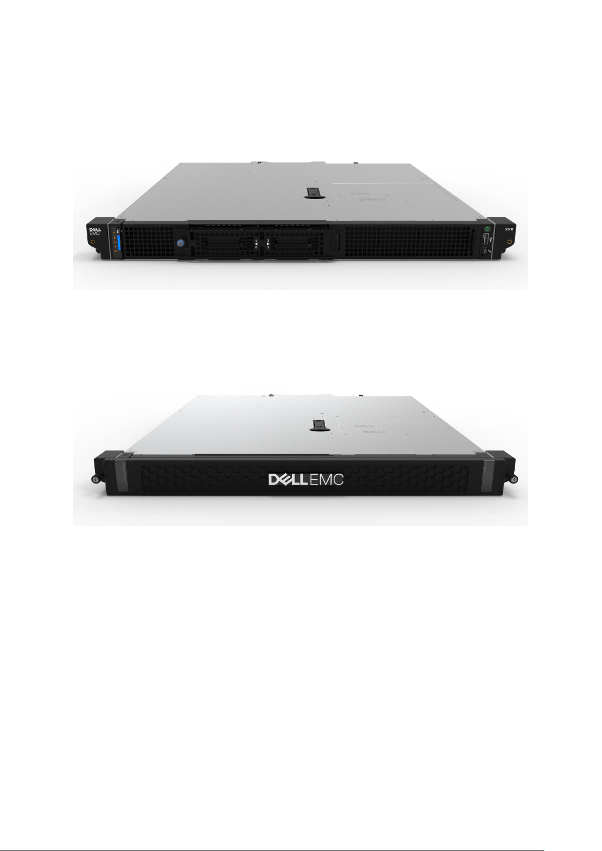
Front view of XR11 rear accessed chassis
Figure 2. XR11 Rear accessed chassis front view, no bezel
Figure 3. XR11 Rear accessed chassis view with front bezel
Chassis views and features
11
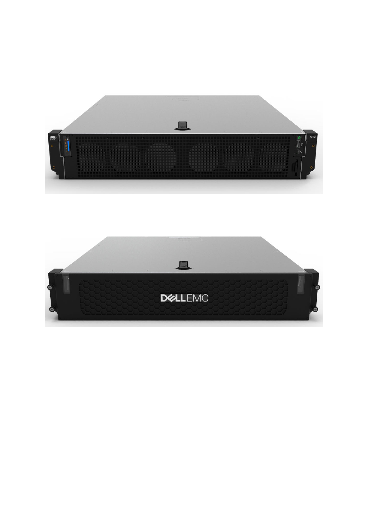
Front view of XR12 front accessed chassis
Figure 4. XR12 Front accessed chassis front views
Figure 5. XR12 Front accessed chassis, front-side view with filter bezel
12
Chassis views and features
Front view of XR12 rear accessed chassis
Figure 6. XR12 Rear accessed chassis front view, no bezel
Figure 7. XR12 Rear accessed chassis view with front bezel
Chassis views and features
13
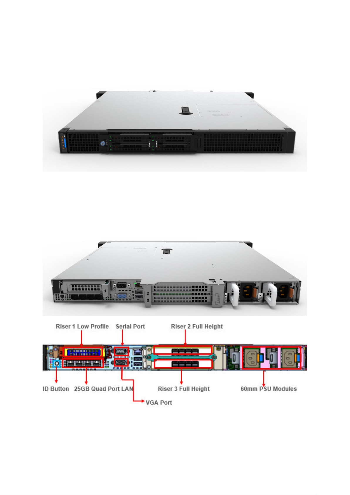
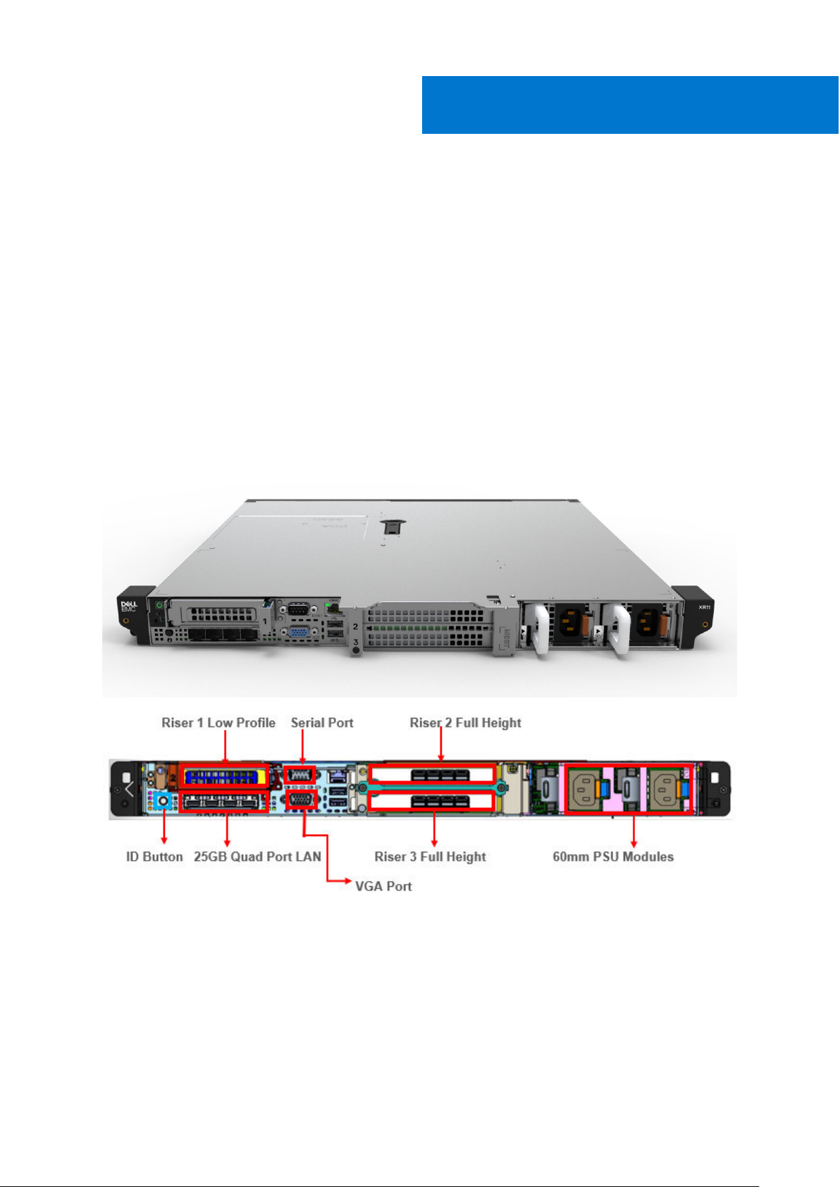
Rear view of XR11 front accessed chassis
Figure 8. XR11 Front accessed chassis rear view
Rear view of XR11 rear accessed chassis
Figure 9. XR11 Rear accessed chassis rear views
14
Chassis views and features
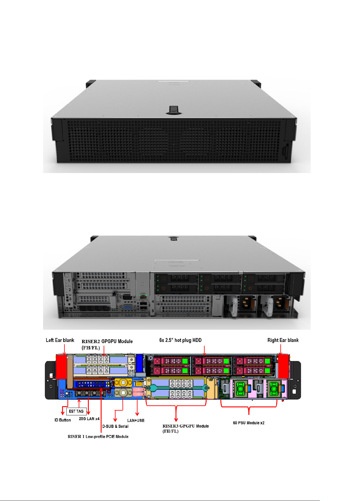
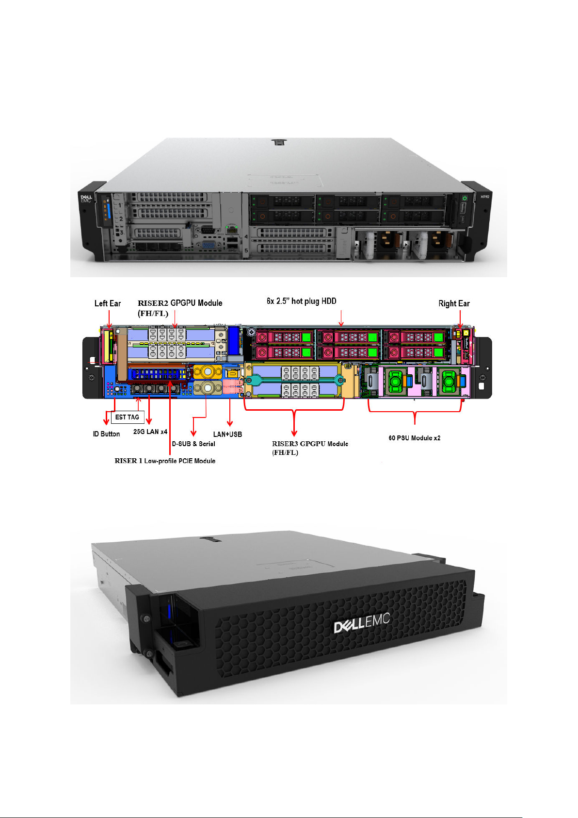
Rear view of XR12 front accessed chassis
Figure 10. XR12 Front accessed chassis rear view
Rear view of XR12 rear accessed chassis
Figure 11. XR12 Rear accessed chassis rear views
Chassis views and features
15
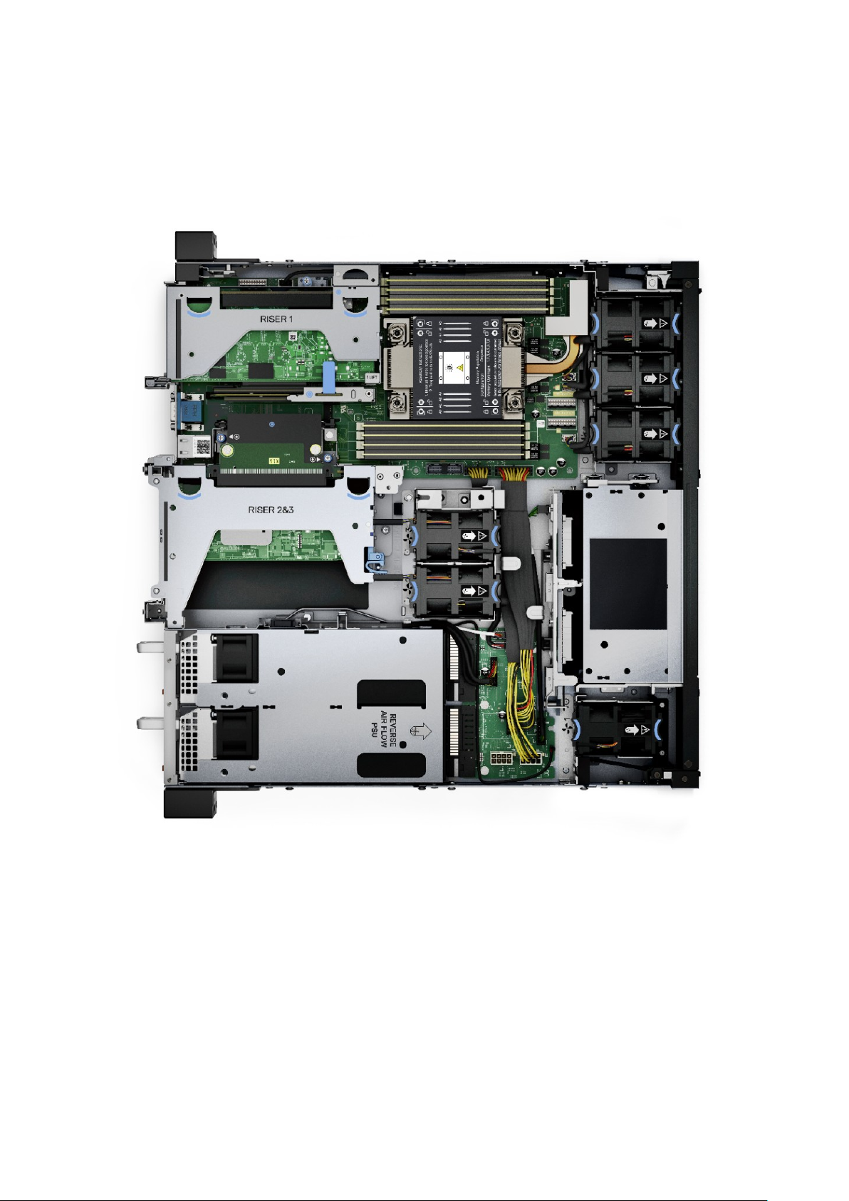
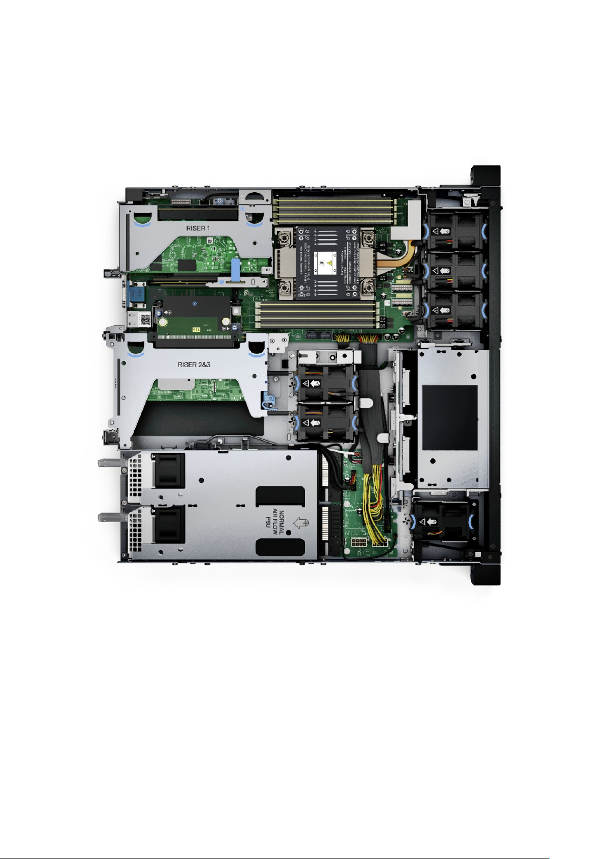
Inside the XR11 front accessed chassis
Figure 12. XR11 Front accessed chassis internal view (no bezel)
16
Chassis views and features
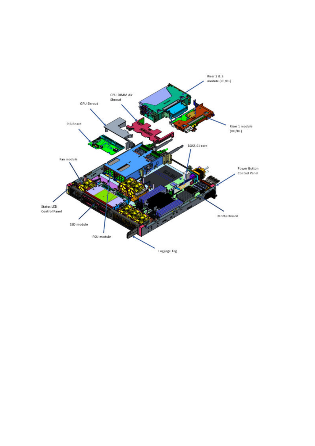
Figure 13. XR11 Front accessed chassis internal exploded view (rear to front)
Chassis views and features
17
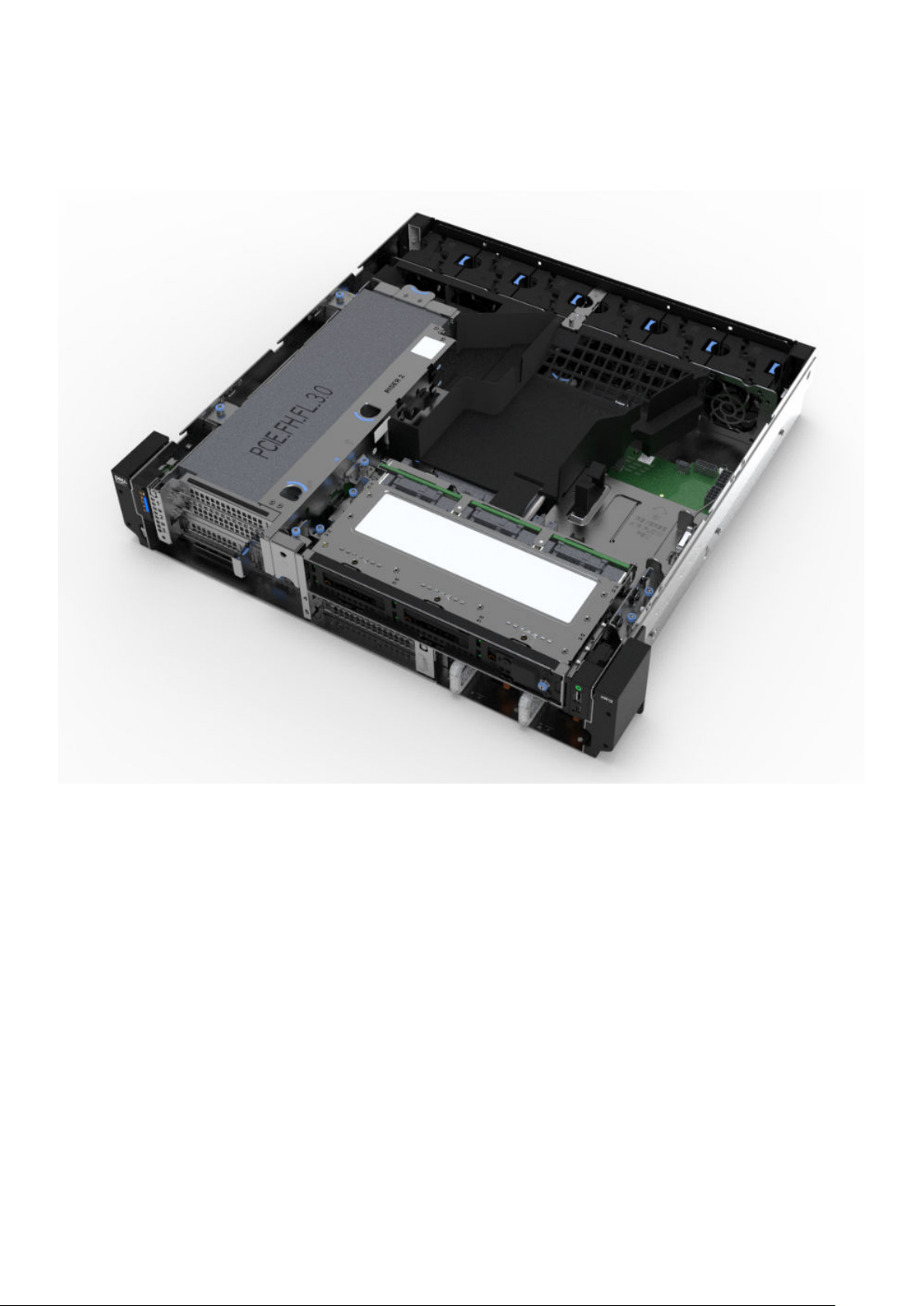
Inside the XR11 rear accessed chassis
Figure 14. XR11 Rear accessed chassis internal view (no bezel)
18
Chassis views and features
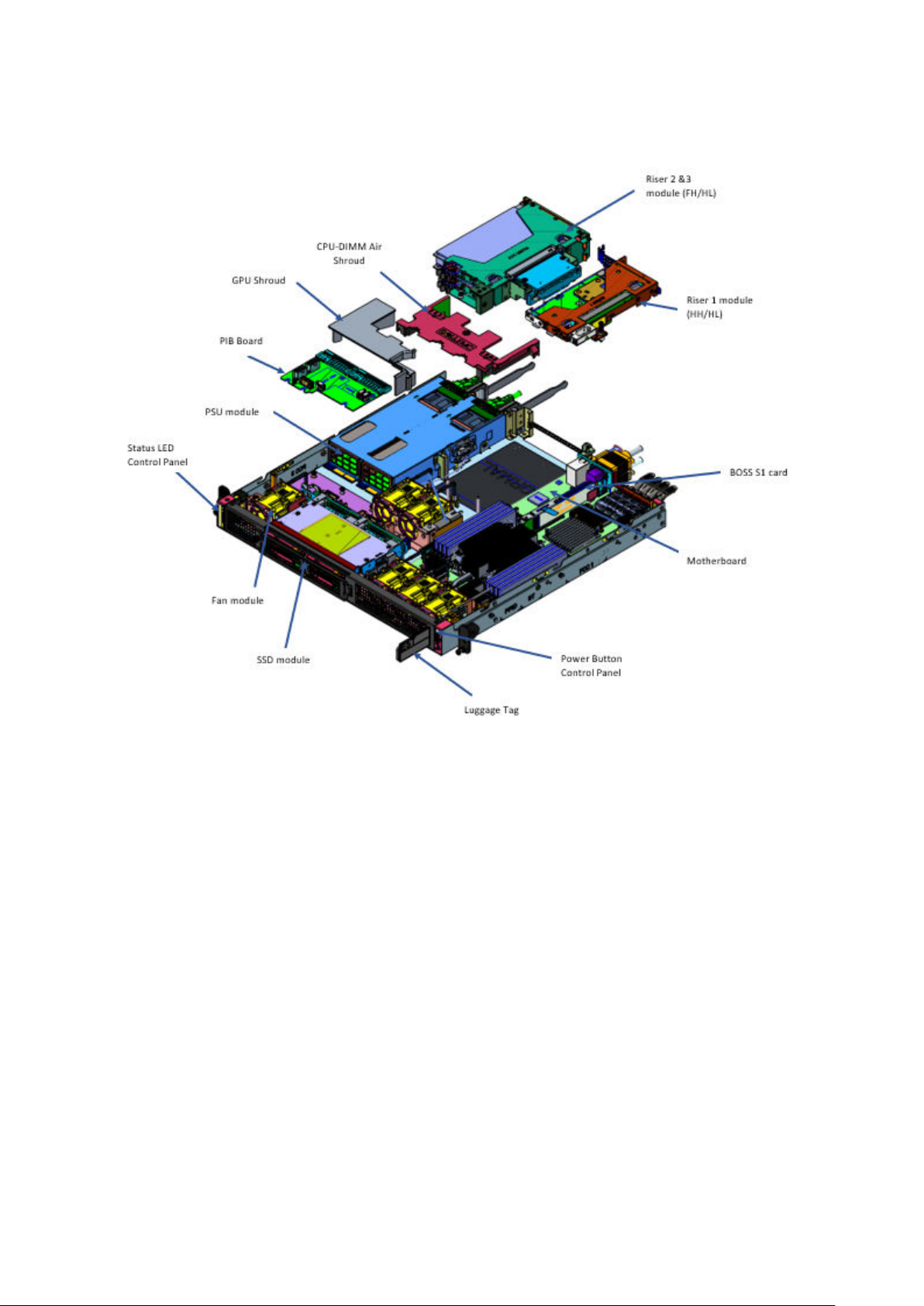
Figure 15. XR11 Rear accessed chassis internal exploded view (no bezel)
Chassis views and features
19
Inside the XR12 front accessed chassis
Figure 16. XR12 Front accessed chassis internal front view (no bezel)
20
Chassis views and features
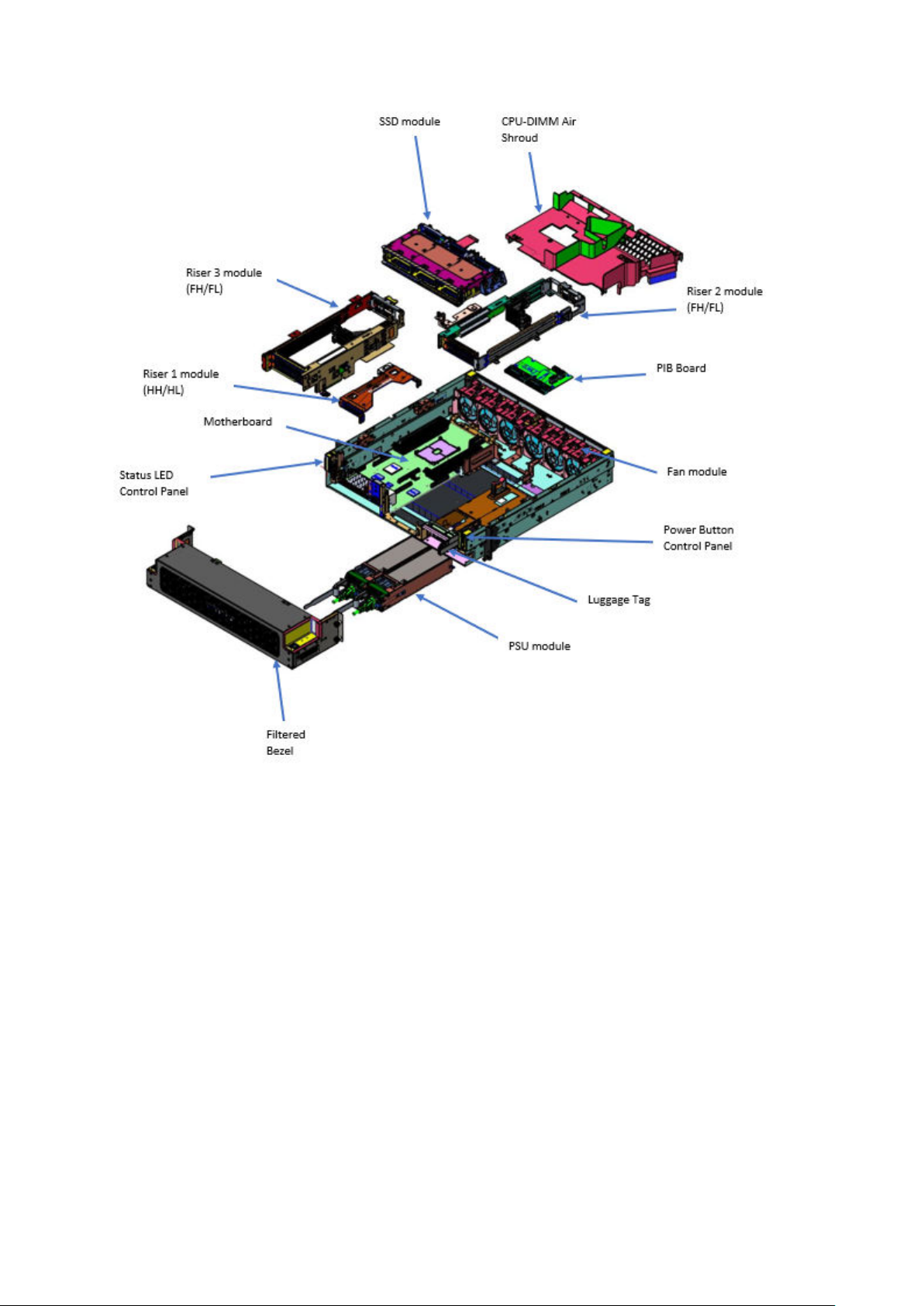
Figure 17. XR12 Front accessed chassis internal exploded view
Chassis views and features
21
 Loading...